

Page 1
Page 2
WARNING: To reduce the risk of fire or electric shock, do not expose this apparatus to rain or moisture.
CAUTION
RISK OF ELECTRIC SHOCK
DO NOT OPEN
ATTENTION: RISQUE DE CHOC ELECTRIQUE NE PAS OUVRIR
CAUTION: TO REDUCE THE RISK OF ELECTRIC SHOCK,
DO NOT REMOVE COVER (OR BACK).
NO USER-SERVICEABLE PARTS INSIDE.
REFER SERVICING TO QUALIFIED SERVICE PERSONNEL.
The lightning flash with arrowhead symbol, within an
equilateral triangle, is intended to alert the user to the
presence of uninsulated “dangerous voltage” within the
product’s enclosure that may be of sufficient magnitude to
constitute a risk of electric shock to persons.
The exclamation point within an equilateral triangle is
intended to alert the user to the presence of important
operating and maintenance (servicing) instructions in the
literature accompanying the product.
INSTRUCTIONS PERTAINING TO A RISK OF FIRE, ELECTRIC SHOCK, OR INJURY TO PERSONS.
IMPORTANT SAFETY INSTRUCTIONS
SAVE THESE INSTRUCTIONS
WARNING - When using electric products, basic precautions should always be followed, including the following:
1. Read these instructions.
2. Keep these instructions.
3. Heed all warnings.
4. Follow all instructions.
5. Do not use this apparatus near water.
6. Clean only with a dry cloth.
7. Do not block any of the ventilation openings. Install in
accordance with the manufacturers instructions.
8. Do not install near any heat sources such as radiators,
heat registers, stoves, or other apparatus (including
amplifiers) that produce heat.
9. Do not defeat the safety purpose of the polarized or
grounding-type plug. A polarized plug has two blades with
one wider than the other. A grounding type plug has two
blades and a third grounding prong. The wide blade or the
third prong are provided for your safety. If the provided plug
does not fit into your outlet, consult an electrician for
replacement of the obsolete outlet.
10. Protect the power cord from being walked on or pinched
particularly at plugs, convenience receptacles, and the
point where they exit from the apparatus.
11. Only use attachments/accessories specified by the
manufacturer.
12. Use only with the cart, stand, tripod, bracket,
or table specified by the manufacturer, or
sold with the apparatus. When a cart is used,
use caution when moving the cart/apparatus
combination to avoid injury from tip-over.
13. Unplug this apparatus during lightning storms or when
unused for long periods of time.
14. Refer all servicing to qualified service personnel. Servicing
is required when the apparatus has been damaged in any
way, such as power-supply cord or plug is damaged, liquid
has been spilled or objects have fallen into the apparatus,
the apparatus has been exposed to rain or moisture, does
not operate normally, or has been dropped.
For the U.K.
WARNING:
IMPORTANT:
As the colours of the wires in the mains lead of this apparatus may not correspond with the coloured markings identifying
the terminals in your plug, proceed as follows:
The wire which is coloured GREEN-AND-YELLOW must be connected to the terminal in the plug which is marked by the
letter E or by the safety earth symbol or coloured GREEN or GREEN-AND-YELLOW.
The wire which is coloured BLUE must be connected to the terminal which is marked with the letter N or coloured BLACK.
The wire which is coloured BROWN must be connected to the terminal which is marked with the letter L or coloured RED.
THIS APPARATUS MUST BE EARTHED
THE WIRES IN THIS MAINS LEAD ARE COLOURED IN ACCORDANCE WITH THE FOLLOWING CODE.
GREEN-AND-YELLOW: EARTH, BLUE: NEUTRAL, BROWN: LIVE
Page 3
Owner’s Manual
How to obtain a PDF of the owner’s manual
PDF les of the owner’s manual and supplementary material for this product can be obtained from the
Roland website.
• JUPITER-80 Owner’s Manual (this document)
• Parameter List *
• MIDI Implementation *
* These are not included with the product; you may download them as necessary.
Visit the following URL, choose “owner’s manuals,” and search for the model name “JUPITER-80.”
http://www.roland.com/support/en/
Before using this unit, carefully read the sections entitled: “IMPORTANT SAFETY INSTRUCTIONS” (Owner’s Manual p. 2), “USING
THE UNIT SAFELY” (Owner’s Manual p. 4), and “IMPORTANT NOTES” (Owner’s Manual p. 5). These sections provide important
information concerning the proper operation of the unit. Additionally, in order to feel assured that you have gained a good
grasp of every feature provided by your new unit, Owner’s Manual should be read in its entirety. The manual should be saved
and kept on hand as a convenient reference.
Copyright © 2011 ROLAND CORPORATION
All rights reserved. No part of this publication may be reproduced in any form without the written permission of ROLAND
CORPORATION.
Roland, COSM, and SuperNATURAL are either registered trademarks or trademarks of
Roland Corporation in the United States and/or other countries.
Page 4

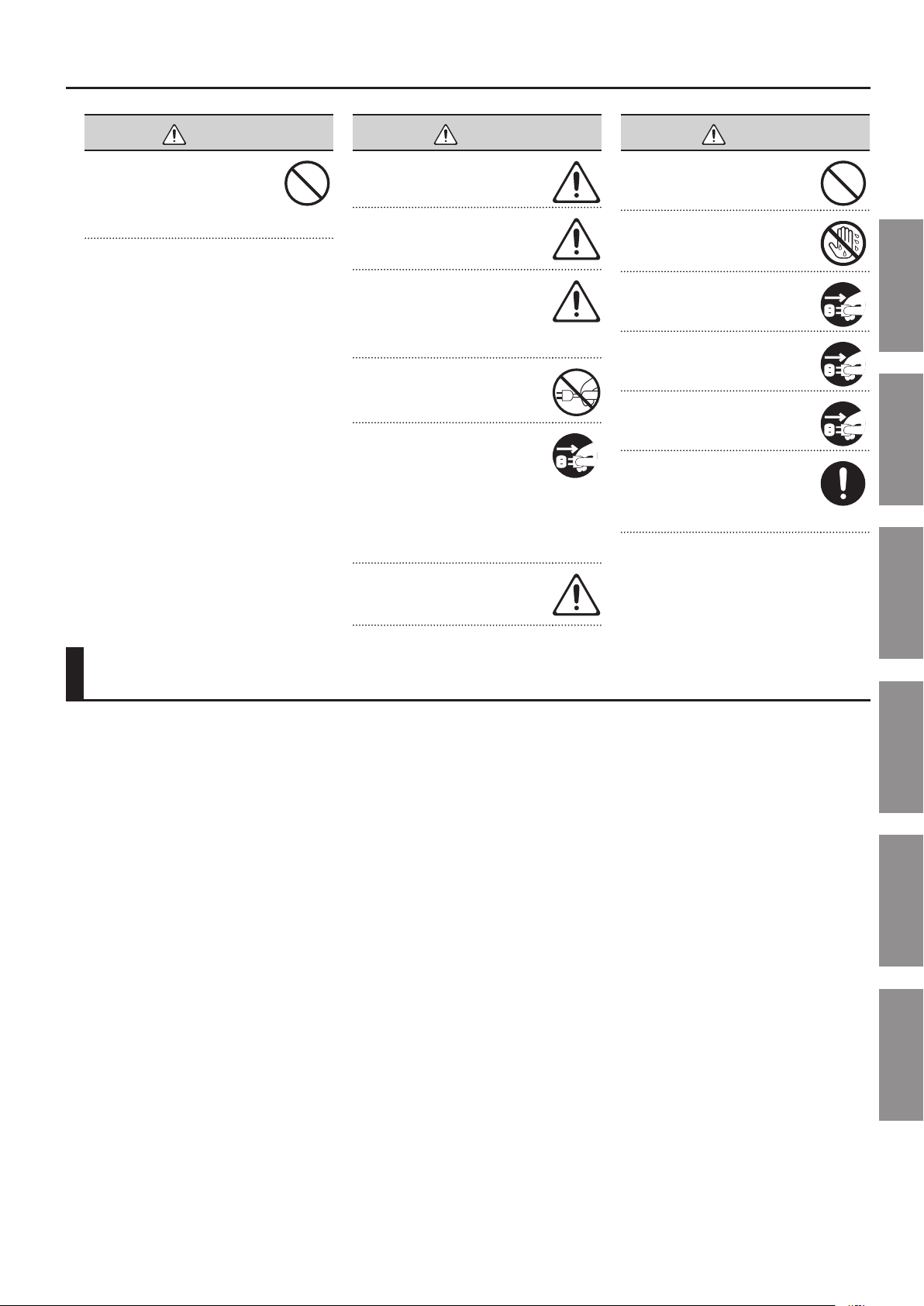
USING THE UNIT SAFETY
About WARNING and CAUTION Notices
Used for instructions intended to alert the
user to the risk of death or severe injury
should the unit be used improperly.
Used for instructions intended to alert the
user to the risk of injury or material
damage should the unit be used
improperly.
* Material damage refers to damage or
other adverse effects caused with
respect to the home and all its
furnishings, as well to domestic animals
or pets.
ALWAYS OBSERVE THE FOLLOWING
WARNING
Connect mains plug of this model to a
mains socket outlet with a protective
earthing connection.
Do not open or perform any internal
modications on the unit.
Do not attempt to repair the unit, or
replace parts within it (except when this
manual provides specic instructions
directing you to do so). Refer all servicing
to your retailer, the nearest Roland Service
Center, or an authorized Roland distributor, as listed on the “Information” page.
Never install the unit in any of the
following locations.
• Subject to temperature extremes
(e.g., direct sunlight in an enclosed
vehicle, near a heating duct, on top of
heat-generating equipment); or are
• Damp (e.g., baths, washrooms, on wet
oors); or are
• Exposed to steam or smoke; or are
• Subject to salt exposure; or are
• Humid; or are
• Exposed to rain; or are
• Dusty or sandy; or are
• Subject to high levels of vibration and
shakiness.
This unit should be used only with a stand
that is recommended by Roland.
When using the unit with a stand
recommended by Roland, the stand must
be carefully placed so it is level and sure
to remain stable. If not using a stand, you
still need to make sure that any location
you choose for placing the unit provides a
level surface that will properly support the
unit, and keep it from wobbling.
The unit should be connected to a power
supply only of the type described as
marked on the rear side of unit.
Use only the attached power-supply cord.
Also, the supplied power cord must not be
used with any other device.
Do not excessively twist or bend the
power cord, nor place heavy objects on it.
Doing so can damage the cord, producing
severed elements and short circuits.
Damaged cords are re and shock hazards!
This unit, either alone or in combination
with an amplier and headphones or
speakers, may be capable of producing
sound levels that could cause permanent
hearing loss. Do not operate for a long
period of time at a high volume level, or
at a level that is uncomfortable. If you
experience any hearing loss or ringing
in the ears, you should immediately stop
using the unit, and consult an audiologist.
Never allow foreign objects (e.g.,
ammable objects, coins, wires) or liquids
(e.g., water or juice) to enter this product.
Doing so may cause short circuits, faulty
operation, or other malfunctions.
About the Symbols
The symbol alerts the user to important instructions or
warnings.The specific meaning of the symbol is
determined by the design contained within the triangle. In
the case of the symbol at left, it is used for general
cautions, warnings, or alerts to danger.
The symbol alerts the user to items that must never be
carried out (are forbidden). The specific thing that must
not be done is indicated by the design contained within
the circle. In the case of the symbol at left, it means that
the unit must never be disassembled.
The symbol alerts the user to things that must be
carried out. The specific thing that must be done is
indicated by the design contained within the circle. In the
case of the symbol at left, it means that the power-cord
plug must be unplugged from the outlet.
WARNING
WARNING
Immediately turn the power o, remove
the power cord from the outlet, and
request servicing by your retailer, the
nearest Roland Service Center, or an
authorized Roland distributor, as listed on
the “Information” page when:
• The power-supply cord or the plug has
been damaged; or
• If smoke or unusual odor occurs
• Objects have fallen into, or liquid has
been spilled onto the unit; or
• The unit has been exposed to rain (or
otherwise has become wet); or
• The unit does not appear to operate
normally or exhibits a marked change in
performance.
In households with small children, an
adult should provide supervision until the
child is capable of following all the rules
essential for the safe operation of the unit.
Protect the unit from strong impact.
(Do not drop it!)
Do not force the unit’s power-supply cord
to share an outlet with an unreasonable
number of other devices. Be especially
careful when using extension cords—the
total power used by all devices you have
connected to the extension cord’s outlet
must never exceed the power rating
(watts/amperes) for the extension cord.
Excessive loads can cause the insulation
on the cord to heat up and eventually
melt through.
Before using the unit in a foreign country,
consult with your retailer, the nearest
Roland Service Center, or an authorized
Roland distributor, as listed on the
“Information” page.
4
Page 5
IMPORTANT NOTES
WARNING
DO NOT play a CD-ROM disc on a
conventional audio CD player. The resulting sound may be of a level that could
cause permanent hearing loss. Damage
to speakers or other system components
may result.
CAUTION
The unit should be located so that its
location or position does not interfere
with its proper ventilation.
This JUPITER-80 for use only with Roland
stand KS-J8, KS-G8, and KS-18Z. Use with
other stands is capable of resulting in
instability causing possible injury.
Even if you observe the cautions given
in the owner’s manual, certain types of
handling may allow this product to fall
from the stand, or cause the stand to
overturn. Please be mindful of any safety
issues before using this product.
Always grasp only the plug on the
power-supply cord when plugging into, or
unplugging from, an outlet or this unit.
At regular intervals, you should unplug
the power plug and clean it by using
a dry cloth to wipe all dust and other
accumulations away from its prongs.
Also, disconnect the power plug from
the power outlet whenever the unit is to
remain unused for an extended period of
time. Any accumulation of dust between
the power plug and the power outlet can
result in poor insulation and lead to re.
Try to prevent cords and cables from
becoming entangled. Also, all cords and
cables should be placed so they are out of
the reach of children.
CAUTION
Never climb on top of, nor place heavy
objects on the unit.
Never handle the power cord or its plugs
with wet hands when plugging into, or
unplugging from, an outlet or this unit.
Before moving the unit, disconnect the
power plug from the outlet, and pull out
all cords from external devices.
Before cleaning the unit, turn o the
power and unplug the power cord from
the outlet (p. 20).
Whenever you suspect the possibility of
lightning in your area, pull the plug on the
power cord out of the outlet.
To prevent accidental ingestion of the
parts listed below, always keep them out
of the reach of small children.
• Removable Parts
Screw for USB memory protector (p. 78)
Introduction Playing Sounds Editing Sounds
IMPORTANT NOTES
Power Supply
• Do not connect this unit to same electrical outlet
that is being used by an electrical appliance that
is controlled by an inverter (such as a refrigerator, washing machine, microwave oven, or air
conditioner), or that contains a motor. Depending
on the way in which the electrical appliance is
used, power supply noise may cause this unit to
malfunction or may produce audible noise. If it
is not practical to use a separate electrical outlet,
connect a power supply noise lter between this
unit and the electrical outlet.
• Before connecting this unit to other devices, turn
o the power to all units. This will help prevent
malfunctions and/or damage to speakers or other
devices.
• Although the LCD and LEDs are switched o
when the POWER switch is switched o, this does
not mean that the unit has been completely
disconnected from the source of power. If you need
to turn o the power completely, rst turn o the
POWER switch, then unplug the power cord from
the power outlet. For this reason, the outlet into
which you choose to connect the power cord’s plug
should be one that is within easy reach and readily
accessible.
Placement
• Using the unit near power ampliers (or other
equipment containing large power transformers)
may induce hum. To alleviate the problem, change
the orientation of this unit; or move it farther away
from the source of interference.
• This device may interfere with radio and television
reception. Do not use this device in the vicinity of
such receivers.
• Noise may be produced if wireless communications
devices, such as cell phones, are operated in the
vicinity of this unit. Such noise could occur when
receiving or initiating a call, or while conversing.
Should you experience such problems, you should
relocate such wireless devices so they are at a
greater distance from this unit, or switch them o.
• Do not expose the unit to direct sunlight, place
it near devices that radiate heat, leave it inside
an enclosed vehicle, or otherwise subject it to
temperature extremes. Excessive heat can deform
or discolor the unit.
• When moved from one location to another where
the temperature and/or humidity is very dierent,
water droplets (condensation) may form inside
the unit. Damage or malfunction may result if you
attempt to use the unit in this condition. Therefore,
before using the unit, you must allow it to stand
for several hours, until the condensation has
completely evaporated.
• Do not allow objects to remain on top of the
keyboard. This can be the cause of malfunction,
such as keys ceasing to produce sound.
• Depending on the material and temperature of the
surface on which you place the unit, its rubber feet
may discolor or mar the surface.
You can place a piece of felt or cloth under the
rubber feet to prevent this from happening. If you
do so, please make sure that the unit will not slip or
move accidentally.
• Do not put anything that contains water on this
unit. Also, avoid the use of insecticides, perfumes,
alcohol, nail polish, spray cans, etc., near the unit.
Swiftly wipe away any liquid that spills on the unit
using a dry, soft cloth.
Maintenance
• For everyday cleaning wipe the unit with a soft,
dry cloth or one that has been slightly dampened
with water. To remove stubborn dirt, use a cloth
impregnated with a mild, non-abrasive detergent.
Afterwards, be sure to wipe the unit thoroughly
with a soft, dry cloth.
• Never use benzine, thinners, alcohol or solvents of
any kind, to avoid the possibility of discoloration
and/or deformation.
Repairs and Data
• Please be aware that all data contained in the
unit’s memory may be lost when the unit is sent for
repairs. Important data should always be backed up
USB ash drives, or written down on paper (when
possible). During repairs, due care is taken to avoid
the loss of data. However, in certain cases (such
as when circuitry related to memory itself is out
of order), we regret that it may not be possible to
restore the data, and Roland assumes no liability
concerning such loss of data.
Other Convenient
Functions
Connecting Other
Equipment
Appendix
5
Page 6
IMPORTANT NOTES
Additional Precautions
• Please be aware that the contents of memory can
be irretrievably lost as a result of a malfunction,
or the improper operation of the unit. To protect
yourself against the risk of loosing important data,
we recommend that you periodically save a backup
copy of important data you have stored in the unit’s
memory on USB ash drives.
• Unfortunately, it may be impossible to restore
the contents of data that was stored in the unit’s
memory and USB ash drives once it has been lost.
Roland Corporation assumes no liability concerning
such loss of data.
• Use a reasonable amount of care when using the
unit’s buttons, sliders, or other controls; and when
using its jacks and connectors. Rough handling can
lead to malfunctions.
• Never strike or apply strong pressure to the display.
• When connecting / disconnecting all cables, grasp
the connector itself—never pull on the cable. This
way you will avoid causing shorts, or damage to the
cable’s internal elements.
• A small amount of heat will radiate from the unit
during normal operation.
• To avoid disturbing your neighbors, try to keep
the unit’s volume at reasonable levels. You may
prefer to use headphones, so you do not need to be
concerned about those around you.
• When you need to transport the unit, package it
in the box (including padding) that it came in, if
possible. Otherwise, you will need to use equivalent
packaging materials.
• Use only the specied expression pedal (EV-5; sold
separately). By connecting any other expression
pedals, you risk causing malfunction and/or
damage to the unit.
• Some connection cables contain resistors. Do not
use cables that incorporate resistors for connecting
to this unit. The use of such cables can cause the
sound level to be extremely low, or impossible
to hear. For information on cable specications,
contact the manufacturer of the cable.
• The usable range of D Beam controller will become
extremely small when used under strong direct
sunlight. Please be aware of this when using the D
Beam controller outside.
• The sensitivity of the D Beam controller will change
depending on the amount of light in the vicinity of
the unit. If it does not function as you expect, adjust
the sensitivity as appropriate for the brightness of
your location (p. 84).
Handling External Memories
• Carefully insert the USB ash drives all the way
in—until it is rmly in place.
• USB ash drives are constructed using precision
components; handle the cards carefully, paying
particular note to the following.
• To prevent damage to the cards from static
electricity, be sure to discharge any static
electricity from your own body before
handling the cards.
• Do not touch or allow metal to come into
contact with the contact portion of the cards.
• Do not bend, drop, or subject cards to strong
shock or vibration.
• Do not keep cards in direct sunlight, in closed
vehicles, or other such locations.
• Do not allow cards to become wet.
• Do not disassemble or modify the cards.
Handling CDs / DVDs
• Avoid touching or scratching the shiny underside
(encoded surface) of the disc. Damaged or dirty
DVD discs may not be read properly. Keep your
discs clean using a commercially available DVD
cleaner.
Copyrights
• Recording, duplication, distribution, sale, lease,
performance, or broadcast of copyrighted material
(musical works, visual works, broadcasts, live
performances, etc.) belonging to a third party in
part or in whole without the permission of the
copyright owner is forbidden by law.
• Do not use this product for purposes that could
infringe on a copyright held by a third party. We
assume no responsibility whatsoever with regard to
any infringements of third-party copyrights arising
through your use of this product.
• The copyright of content in this product (the
sound waveform data, style data, accompaniment
patterns, phrase data, audio loops and image data)
is reserved by Roland Corporation and/or Atelier
Vision Corporation.
• Purchasers of this product are permitted to utilize
said content for the creating, performing, recording
and distributing original musical works.
• Purchasers of this product are NOT permitted to
extract said content in original or modied form,
for the purpose of distributing recorded medium
of said content or making them available on a
computer network.
Licenses / Trademarks
• MMP (Moore Microprocessor Portfolio) refers to a
patent portfolio concerned with microprocessor
architecture, which was developed by Technology
Properties Limited (TPL). Roland has licensed this
technology from the TPL Group.
• MPEG Layer-3 audio compression technology
is licensed from Fraunhofer IIS Corporation and
THOMSON Multimedia Corporation.
• MatrixQuest™ 2010 TEPCO UQUEST, LTD. All rights
reserved.
• Company names and product names appearing
in this document are registered trademarks or
trademarks of their respective owners.
• Never touch the terminals of the USB ash drives.
Also, avoid getting the terminals dirty.
6
• “JUPITER” is a registered trademark of and is
licensed by K.H.S. MUSICAL INSTRUMENT CO. LTD.
in the United States and other countries.
• Cakewalk is a registered trademark of Cakewalk,
Inc. in the United States.
• SONAR is a trademark of Cakewalk, Inc.
Page 7

Contents
USING THE UNIT SAFETY . . . . . . . . . . . . . . . . . . . . . . . . . . . . . . . . . . . . . . . . . 4
IMPORTANT NOTES . . . . . . . . . . . . . . . . . . . . . . . . . . . . . . . . . . . . . . . . . . . . . . 5
Introduction 9
Main Features . . . . . . . . . . . . . . . . . . . . . . . . . . . . . . . . . . . . . . . . . . . . . . . . . .10
Getting Acquainted with the JUPITER-80 . . . . . . . . . . . . . . . . . . . . . . . . .12
How the Sound Generator is Organized . . . . . . . . . . . . . . . . . . . . . . . . .12
Tones . . . . . . . . . . . . . . . . . . . . . . . . . . . . . . . . . . . . . . . . . . . . . . . . . . . .13
Live Sets . . . . . . . . . . . . . . . . . . . . . . . . . . . . . . . . . . . . . . . . . . . . . . . . .14
Parts . . . . . . . . . . . . . . . . . . . . . . . . . . . . . . . . . . . . . . . . . . . . . . . . . . . . .14
Registrations . . . . . . . . . . . . . . . . . . . . . . . . . . . . . . . . . . . . . . . . . . . . .15
About Memory . . . . . . . . . . . . . . . . . . . . . . . . . . . . . . . . . . . . . . . . . . . . . . . .16
Temporary Memory (the Temporary Area) . . . . . . . . . . . . . . . .16
Rewritable Memory . . . . . . . . . . . . . . . . . . . . . . . . . . . . . . . . . . . . . .16
Non-rewritable Memory . . . . . . . . . . . . . . . . . . . . . . . . . . . . . . . . . .16
USB Flash Drive . . . . . . . . . . . . . . . . . . . . . . . . . . . . . . . . . . . . . . . . . .16
USB Memory Song Player/Recorder . . . . . . . . . . . . . . . . . . . . . . . . . . . . .17
Audio les that can be played . . . . . . . . . . . . . . . . . . . . . . . . . . . .17
Audio les that will be saved . . . . . . . . . . . . . . . . . . . . . . . . . . . . .17
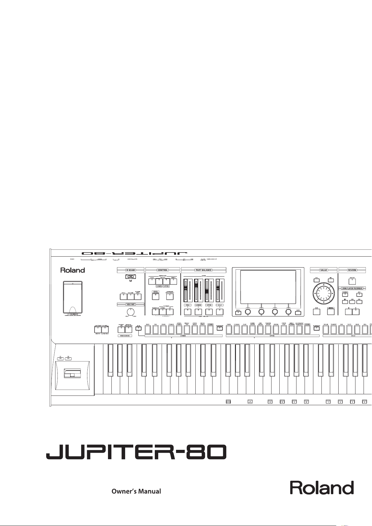
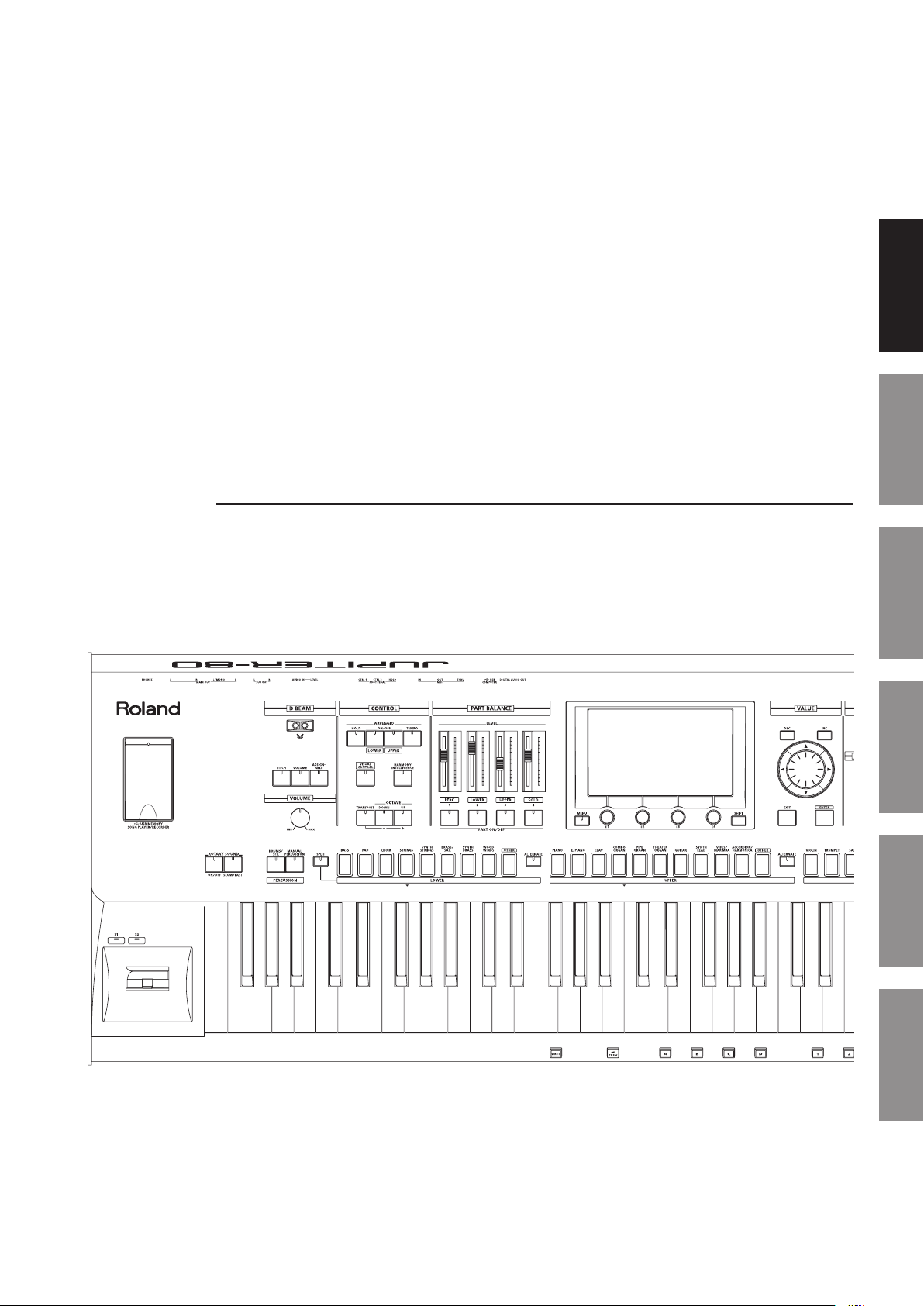
Panel Descriptions . . . . . . . . . . . . . . . . . . . . . . . . . . . . . . . . . . . . . . . . . . . . . .18
Top Panel . . . . . . . . . . . . . . . . . . . . . . . . . . . . . . . . . . . . . . . . . . . . . . . . . . . . . .18
Rear Panel Connections . . . . . . . . . . . . . . . . . . . . . . . . . . . . . . . . . . . . . . . .20
Placing the JUPITER-80 on a Stand . . . . . . . . . . . . . . . . . . . . . . . . . . . . . . .22
Turning the Power On . . . . . . . . . . . . . . . . . . . . . . . . . . . . . . . . . . . . . . . . . . .23
Turning the Power On . . . . . . . . . . . . . . . . . . . . . . . . . . . . . . . . . . . . . . . . . .23
Basic Operation . . . . . . . . . . . . . . . . . . . . . . . . . . . . . . . . . . . . . . . . . . . . . . . .24
Moving the Cursor . . . . . . . . . . . . . . . . . . . . . . . . . . . . . . . . . . . . . . . . . . . . .24
Editing a Value . . . . . . . . . . . . . . . . . . . . . . . . . . . . . . . . . . . . . . . . . . . . . . . . .25
Basic Touch Panel Operation . . . . . . . . . . . . . . . . . . . . . . . . . . . . . . . . . . .27
[SHIFT] Button Operations . . . . . . . . . . . . . . . . . . . . . . . . . . . . . . . . . . . . .28
[MENU] Button Operations . . . . . . . . . . . . . . . . . . . . . . . . . . . . . . . . . . . . .29
Assigning a Name . . . . . . . . . . . . . . . . . . . . . . . . . . . . . . . . . . . . . . . . . . . . . .29
Navigating Between Screens . . . . . . . . . . . . . . . . . . . . . . . . . . . . . . . . . . . .30
Registration screen . . . . . . . . . . . . . . . . . . . . . . . . . . . . . . . . . . . . . . . . . . . .30
Registration Part screen . . . . . . . . . . . . . . . . . . . . . . . . . . . . . . . . . . . . . . . .31
Live Set screen . . . . . . . . . . . . . . . . . . . . . . . . . . . . . . . . . . . . . . . . . . . . . . . . .32
Live Set Eects Routing screen . . . . . . . . . . . . . . . . . . . . . . . . . . . . . . . . .33
Synth Tone Edit (OSC/FILTER/AMP) screen . . . . . . . . . . . . . . . . . . . . . . .33
Tone Blender screen . . . . . . . . . . . . . . . . . . . . . . . . . . . . . . . . . . . . . . . . . . .34
Key Range View screen . . . . . . . . . . . . . . . . . . . . . . . . . . . . . . . . . . . . . . . . .34
MENU screen . . . . . . . . . . . . . . . . . . . . . . . . . . . . . . . . . . . . . . . . . . . . . . . . . .34
Song screen . . . . . . . . . . . . . . . . . . . . . . . . . . . . . . . . . . . . . . . . . . . . . . . . . . .34
Visual Control screen . . . . . . . . . . . . . . . . . . . . . . . . . . . . . . . . . . . . . . . . . . .34
Playing Sounds 35
Selecting the Sound for Each Part (Selecting Live Sets / Tones) . . . .36
Using the Part Sound Buttons to Switch Live Sets or the Solo
Part’s Tone . . . . . . . . . . . . . . . . . . . . . . . . . . . . . . . . . . . . . . . . . . . . . . . . . . . . .36
Instantly Switching the Variation Sounds (Alternate
Button) . . . . . . . . . . . . . . . . . . . . . . . . . . . . . . . . . . . . . . . . . . . . . . . . . .37
Turning Each Part On/O and Adjusting its Volume . . . . . . . . . . . . .37
Playing Drum Sounds and Sound Eects (Percussion) . . . . . . . . . . . . .38
Playing Percussion Sounds and Voice Phrases (Manual
Percussion) . . . . . . . . . . . . . . . . . . . . . . . . . . . . . . . . . . . . . . . . . . . . . . . . . . . .38
Playing Drum Sounds on the Entire Keyboard (Drums/SFX) . . . . . .38
Switching the Sounds Played by Manual Percussion or
Drums/SFX . . . . . . . . . . . . . . . . . . . . . . . . . . . . . . . . . . . . . . . . . . . . . .38
Split Performance . . . . . . . . . . . . . . . . . . . . . . . . . . . . . . . . . . . . . . . . . . . . . .39
Turning Split On . . . . . . . . . . . . . . . . . . . . . . . . . . . . . . . . . . . . . . . . . . . . . . .39
How Split and Parts are Related . . . . . . . . . . . . . . . . . . . . . . . . . . .40
Changing the Split Point . . . . . . . . . . . . . . . . . . . . . . . . . . . . . . . . . . . . . . .40
Switching Registrations . . . . . . . . . . . . . . . . . . . . . . . . . . . . . . . . . . . . . . . . .41
Switching Banks . . . . . . . . . . . . . . . . . . . . . . . . . . . . . . . . . . . . . . . . . . . . . . .41
Switching Registration Sets . . . . . . . . . . . . . . . . . . . . . . . . . . . . . . . . . . . .42
Switching Registrations Consecutively . . . . . . . . . . . . . . . . . . . . . . . . . .42
Using the Arpeggiator . . . . . . . . . . . . . . . . . . . . . . . . . . . . . . . . . . . . . . . . . . 43
Turning the Arpeggiator On . . . . . . . . . . . . . . . . . . . . . . . . . . . . . . . . . . . .43
Setting the Arpeggiator Tempo . . . . . . . . . . . . . . . . . . . . . . . . . . .43
Holding the Arpeggio (HOLD) . . . . . . . . . . . . . . . . . . . . . . . . . . . .43
Editing the Arpeggiator Settings . . . . . . . . . . . . . . . . . . . . . . . . . . . . . . .44
Arpeggio Parameters . . . . . . . . . . . . . . . . . . . . . . . . . . . . . . . . . . . . .44
Creating an Arpeggio Style from a MIDI File (Import) . . . . . .45
Performing With Added Harmony . . . . . . . . . . . . . . . . . . . . . . . . . . . . . . .46
Changing the Harmony Intelligence Type . . . . . . . . . . . . . . . . . . . . . . .46
Controlling the Performance . . . . . . . . . . . . . . . . . . . . . . . . . . . . . . . . . . . .47
Moving Your Hand to Modify the Pitch or Volume (D Beam
Controller) . . . . . . . . . . . . . . . . . . . . . . . . . . . . . . . . . . . . . . . . . . . . . . . . . . . . .47
Changing the Pitch/Applying Vibrato (Pitch Bend/Modulation
Lever) . . . . . . . . . . . . . . . . . . . . . . . . . . . . . . . . . . . . . . . . . . . . . . . . . . . . . . . . .47
Using the Buttons and Knobs to Modify the Sound ([S1] [S2]
buttons / [E1]–[E4] knobs) . . . . . . . . . . . . . . . . . . . . . . . . . . . . . . . . . . . . . .47
Using Pedals . . . . . . . . . . . . . . . . . . . . . . . . . . . . . . . . . . . . . . . . . . . . . . . . . . .48
Sustaining the Notes (Hold Pedal) . . . . . . . . . . . . . . . . . . . . . . . .48
Adding Expression to Your Performance (Control Pedal) . . .48
Controlling the Rotary Eect and Reverb . . . . . . . . . . . . . . . . . . . . . . . . .49
Controlling the Rotary Eect . . . . . . . . . . . . . . . . . . . . . . . . . . . . . . . . . . .49
Controlling Reverb . . . . . . . . . . . . . . . . . . . . . . . . . . . . . . . . . . . . . . . . . . . . .49
Changing the Keyboard Settings . . . . . . . . . . . . . . . . . . . . . . . . . . . . . . . .50
Changing the Pitch by Octaves . . . . . . . . . . . . . . . . . . . . . . . . . . . . . . . . .50
Transposing . . . . . . . . . . . . . . . . . . . . . . . . . . . . . . . . . . . . . . . . . . . . . . . . . . .50
Introduction Playing Sounds Editing Sounds
Other Convenient
Functions
Connecting Other
Equipment
Appendix
7
Page 8

Contents
Editing Sounds 51
Editing a Registration . . . . . . . . . . . . . . . . . . . . . . . . . . . . . . . . . . . . . . . . . . .52
Basic Operation for Registration Editing. . . . . . . . . . . . . . . . . . . . . . . . .52
Saving a Registration . . . . . . . . . . . . . . . . . . . . . . . . . . . . . . . . . . . . . . . . . . .53
Cancelling the Save of a Registration . . . . . . . . . . . . . . . . . . . . .53
Initializing a Registration . . . . . . . . . . . . . . . . . . . . . . . . . . . . . . . . . . . . . . .55
Editing a Live Set . . . . . . . . . . . . . . . . . . . . . . . . . . . . . . . . . . . . . . . . . . . . . . . 56
Basic Editing Operations for Live Sets . . . . . . . . . . . . . . . . . . . . . . . . . . .56
Changing a Live Set’s Tones . . . . . . . . . . . . . . . . . . . . . . . . . . . . . . . . . . . .57
Layer On/O and Volume Adjustment . . . . . . . . . . . . . . . . . . . . . . . . . .58
Switching the MFX (Multi-eects) . . . . . . . . . . . . . . . . . . . . . . . . . . . . . .58
Turning MFX On/O. . . . . . . . . . . . . . . . . . . . . . . . . . . . . . . . . . . . . .59
Adjusting the Eect Send Levels and Eect Output Levels . . . . . . .59
Editing the MFX . . . . . . . . . . . . . . . . . . . . . . . . . . . . . . . . . . . . . . . . . .59
Editing the Tones Assigned to a Layer . . . . . . . . . . . . . . . . . . . . . . . . . . .60
Simultaneously Adjusting Multiple Live Set Parameters (Tone
Blender) . . . . . . . . . . . . . . . . . . . . . . . . . . . . . . . . . . . . . . . . . . . . . . . . . . . . . . .61
Convenient Ways to Use the Tone Blender . . . . . . . . . . . . . . . .62
Saving a Live Set . . . . . . . . . . . . . . . . . . . . . . . . . . . . . . . . . . . . . . . . . . . . . . .62
Cancelling the Save of a Live Set . . . . . . . . . . . . . . . . . . . . . . . . . .63
Initializing a Live Set . . . . . . . . . . . . . . . . . . . . . . . . . . . . . . . . . . . . . . . . . . .64
Copying a Layer . . . . . . . . . . . . . . . . . . . . . . . . . . . . . . . . . . . . . . . . . . . . . . . .65
Editing a Synth Tone . . . . . . . . . . . . . . . . . . . . . . . . . . . . . . . . . . . . . . . . . . . . 66
Volume and On/O Settings for Each Partial . . . . . . . . . . . . . . . . . . . .67
Saving a Synth Tone . . . . . . . . . . . . . . . . . . . . . . . . . . . . . . . . . . . . . . . . . . . .68
Cancelling the Save of a Tone . . . . . . . . . . . . . . . . . . . . . . . . . . . . .68
Initializing a SuperNATURAL Synth Tone/Partial . . . . . . . . . . . . . . . . .69
Copying a Partial . . . . . . . . . . . . . . . . . . . . . . . . . . . . . . . . . . . . . . . . . . . . . . .69
Other Convenient Functions 71
Using the USB Memory Song Player/Recorder . . . . . . . . . . . . . . . . . . . .72
Basic Operations in the Song Screen . . . . . . . . . . . . . . . . . . . . . . . . . . . .72
Playback . . . . . . . . . . . . . . . . . . . . . . . . . . . . . . . . . . . . . . . . . . . . . . . . . . . . . . .72
Minimizing Sounds in the Center (Center Cancel) . . . . . . . . .73
Changing the Playback Speed or Pitch . . . . . . . . . . . . . . . . . . . .73
Adjusting the Balance of Frequency Ranges (Equalizer) . . . .73
Looping a Specic Region of Time . . . . . . . . . . . . . . . . . . . . . . . .74
Playing Audio Files Consecutively (Chain Play) . . . . . . . . . . . .74
Creating a Folder . . . . . . . . . . . . . . . . . . . . . . . . . . . . . . . . . . . . . . . . .75
Deleting an Audio File or Folder . . . . . . . . . . . . . . . . . . . . . . . . . .75
Renaming an Audio File or Folder . . . . . . . . . . . . . . . . . . . . . . . . .75
Moving an Audio File or Folder . . . . . . . . . . . . . . . . . . . . . . . . . . .76
Basic Operations in the Audio Rec Standby Screen . . . . . . . . . . . . . .77
Recording . . . . . . . . . . . . . . . . . . . . . . . . . . . . . . . . . . . . . . . . . . . . . . . . . . . . .77
Audio Signal Flow . . . . . . . . . . . . . . . . . . . . . . . . . . . . . . . . . . . . . . . . . . . . . .78
Using the Included USB Memory Protector . . . . . . . . . . . . . . . . . . . . . .78
The JUPITER-80’s System Settings . . . . . . . . . . . . . . . . . . . . . . . . . . . . . . .83
Making System Settings . . . . . . . . . . . . . . . . . . . . . . . . . . . . . . . . . . . . . . . .83
Saving the System Settings . . . . . . . . . . . . . . . . . . . . . . . . . . . . . . . . . . . . .83
System Parameters . . . . . . . . . . . . . . . . . . . . . . . . . . . . . . . . . . . . . . . . . . . . .83
SETUP . . . . . . . . . . . . . . . . . . . . . . . . . . . . . . . . . . . . . . . . . . . . . . . . . . .83
LIVE SET/TONE BUTTONS . . . . . . . . . . . . . . . . . . . . . . . . . . . . . . . . .87
INFORMATION . . . . . . . . . . . . . . . . . . . . . . . . . . . . . . . . . . . . . . . . . . .87
Restoring the Factory Settings (Factory Reset) . . . . . . . . . . . . . . . . . .87
Connecting Other Equipment 89
Connecting to Your Computer via USB . . . . . . . . . . . . . . . . . . . . . . . . . . . 90
Connecting the JUPITER-80 to Your Computer . . . . . . . . . . . .90
Connecting an External MIDI Device . . . . . . . . . . . . . . . . . . . . . . . . . . . . .91
About MIDI . . . . . . . . . . . . . . . . . . . . . . . . . . . . . . . . . . . . . . . . . . . . . . . . . . . .91
About MIDI Connectors . . . . . . . . . . . . . . . . . . . . . . . . . . . . . . . . . .91
Using the JUPITER-80 as a Master Keyboard (External Part
Settings) . . . . . . . . . . . . . . . . . . . . . . . . . . . . . . . . . . . . . . . . . . . . . . . . . . . . . . .91
Enabling the External Part Settings . . . . . . . . . . . . . . . . . . . . . . .91
Specifying the Transmit Channel . . . . . . . . . . . . . . . . . . . . . . . . . .92
Specifying the Sound for Each Channel . . . . . . . . . . . . . . . . . . .92
Detailed Settings for External Parts . . . . . . . . . . . . . . . . . . . . . . .92
Playing the JUPITER-80 from an External MIDI Device . . . . . . . . . . .93
Setting the Receive Channel . . . . . . . . . . . . . . . . . . . . . . . . . . . . . .93
Setting the Program Change Receive Switch . . . . . . . . . . . . . .93
Synchronizing with an External MIDI Device . . . . . . . . . . . . . . . . . . . .94
Controlling Visuals . . . . . . . . . . . . . . . . . . . . . . . . . . . . . . . . . . . . . . . . . . . . . .95
What is Visual Control? . . . . . . . . . . . . . . . . . . . . . . . . . . . . . . . . . . . . . . . . .95
Turning Visual Control On/O . . . . . . . . . . . . . . . . . . . . . . . . . . . . . . . . . .95
Visual Control Settings . . . . . . . . . . . . . . . . . . . . . . . . . . . . . . . . . . . . . . . . .96
Appendix 97
Error Message List . . . . . . . . . . . . . . . . . . . . . . . . . . . . . . . . . . . . . . . . . . . . . . 98
Troubleshooting . . . . . . . . . . . . . . . . . . . . . . . . . . . . . . . . . . . . . . . . . . . . . . . .99
Specications . . . . . . . . . . . . . . . . . . . . . . . . . . . . . . . . . . . . . . . . . . . . . . . . 101
MIDI Implementation Chart . . . . . . . . . . . . . . . . . . . . . . . . . . . . . . . . . . . 102
Index . . . . . . . . . . . . . . . . . . . . . . . . . . . . . . . . . . . . . . . . . . . . . . . . . . . . . . . . 103
Settings and Convenient Functions . . . . . . . . . . . . . . . . . . . . . . . . . . . . . . 79
Backing Up All Settings to a USB Flash Drive . . . . . . . . . . . . . . . . . . . .79
Restoring Backed-up Settings from a USB Flash Drive . . . . .80
Backing Up USB Flash Drive Data to a Computer . . . . . . . . . . . . . . . .80
Restoring Backed-up Data from a Computer to a USB
Flash Drive . . . . . . . . . . . . . . . . . . . . . . . . . . . . . . . . . . . . . . . . . . . . . . .80
Initializing a USB Flash Drive (Format) . . . . . . . . . . . . . . . . . . . . . . . . . . .81
Disabling the Registration Buttons. . . . . . . . . . . . . . . . . . . . . . . . . . . . . .81
Exchanging Registration Sets . . . . . . . . . . . . . . . . . . . . . . . . . . . . . . . . . . .82
Calibrating the Touch Panel . . . . . . . . . . . . . . . . . . . . . . . . . . . . . . . . . . . .82
8
Page 9
Introduction
Introduction Playing Sounds Editing Sounds
Other Convenient
Functions
Connecting Other
Equipment
Appendix
Page 10
Main Features
The JUPITER-80 is Roland’s agship synthesizer, delivering powerful, SuperNATURAL sounds and stunning realtime performance. It includes
numerous cutting-edge SuperNATURAL sounds generated by Behavior Modeling Technology, bringing you unprecedentedly natural and rich
expressive possibilities.
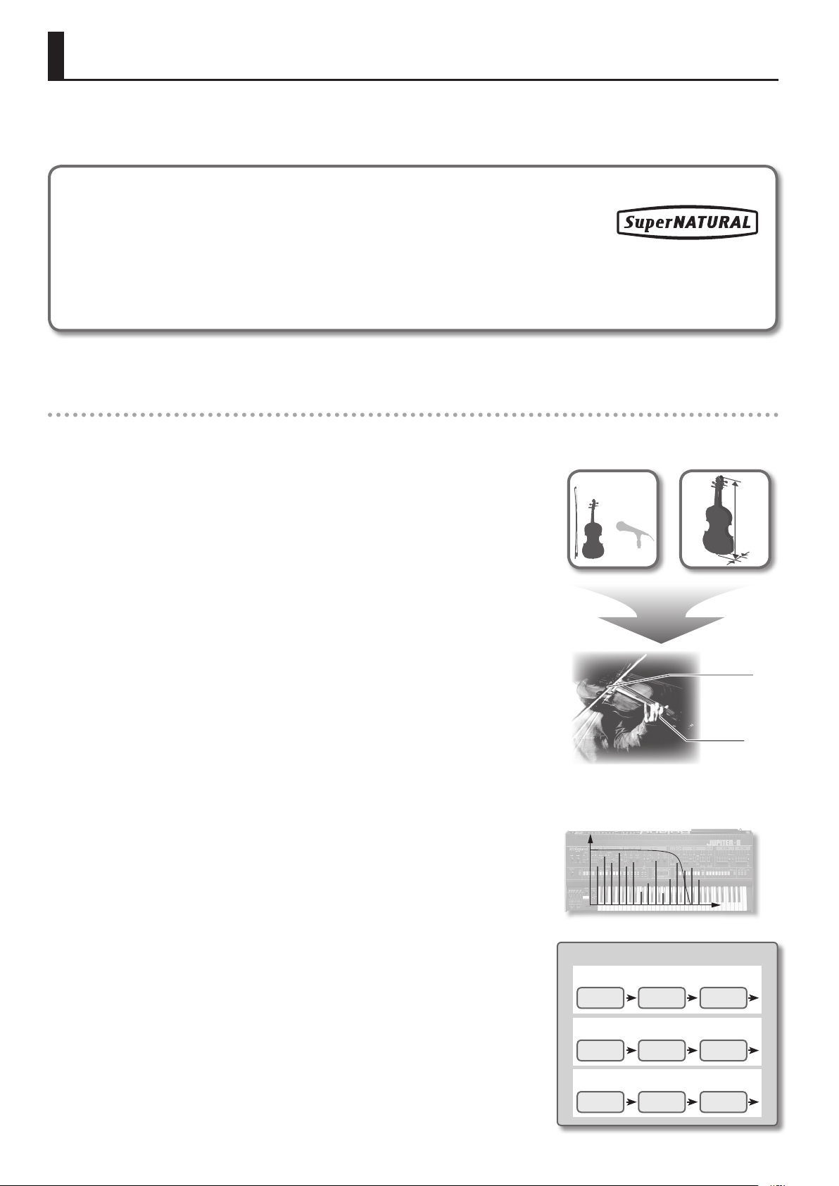
What are SuperNATURAL Tones?
Taking advantage of Behavior Modeling Technology, SuperNATURAL is Roland’s exclusive sound set
that achieves a new level of realism and expression that were dicult to realize with previous sound
generators.
Behavior Modeling Technology
Not only physical modeling of the instruments, Roland takes it a step further by modeling the instrument’s distinctive behavior that responds
to how the performer plays, resulting in true-to-life, expressive sounds in realtime.
A world of new sounds possible only with SuperNATURAL
Numerous peerless and powerful SuperNATURAL sounds are built in
SuperNATURAL Acoustic Tones
The JUPITER-80 provides SuperNATURAL Acoustic Tones, which reproduce not merely the sound
of acoustic instruments, but also their performance expression.
A dedicated sound generator suitable for each tone automatically analyzes dierences in the
phrases, chords, and melodies played by the musician.
SuperNATURAL Acoustic Tones represent a completely new sound-generating technology, one
which not only reproduces the sounds of acoustic instruments, but also uses Behavior Modeling
Technology to model the way in which each instrument uniquely responds to the performance
expression of the player.
In contrast to the old method of seeking realism merely in the sound’s waveform, this is a major
advance which models the details of how the sound of each individual instrument responds to
the performer’s playing.
While previous physical modeling sound generators model the structure of an instrument
(such as the shape of its resonator, the length of the tube, and the material of the vibrating
parts), Behavior Modeling Technology additionally models the response and movement of each
specic instrument as it reacts to performance techniques such as trills, portamento, vibrato, and
dynamics.
This goes beyond mere reproduction of the sound—it makes it possible for the expressions and
movements distinctive of an instrument to be expressed on a synthesizer.
For example, the SuperNATURAL Acoustic Tone “Violin” lets you obtain—by playing the
keyboard—an expressive solo violin sound that’s so realistic, you might think a violinist is actually
playing it.
You can also use the pitch bend and modulation lever and the assignable buttons ([S1], [S2]) to
freely reproduce the richly expressive performances that are distinctive of acoustic instruments.
SuperNATURAL Synth Tones
The JUPITER-80 features SuperNATURAL Synth Tones, which realistically deliver everything from
vintage analog synths to digital synths.
The distinctive behavior of an analog synth’s oscillators and lters has been analyzed in order to
reproduce their unique sound.
“Expressions” “Operations”
Crescendo
Glissando technique
Vibrato
SuperNATURAL Synth Tone
Partial 1
OSC FILTER AMP
Partial 2
Each Synth Tone provides three sets of OSC, FILTER, AMP, and LFO, allowing powerful synthesis to
be accomplished using just a single tone. The oscillators oer not only analog waveforms based
on vintage synths, but also give you a choice of PCM waveforms containing distinctive digital
synth sounds. Full-screen graphics allow you to intuitively create any type of synth sound, from
analog to digital.
10
OSC FILTER AMP
Partial 3
OSC FILTER AMP
Page 11
Main Features
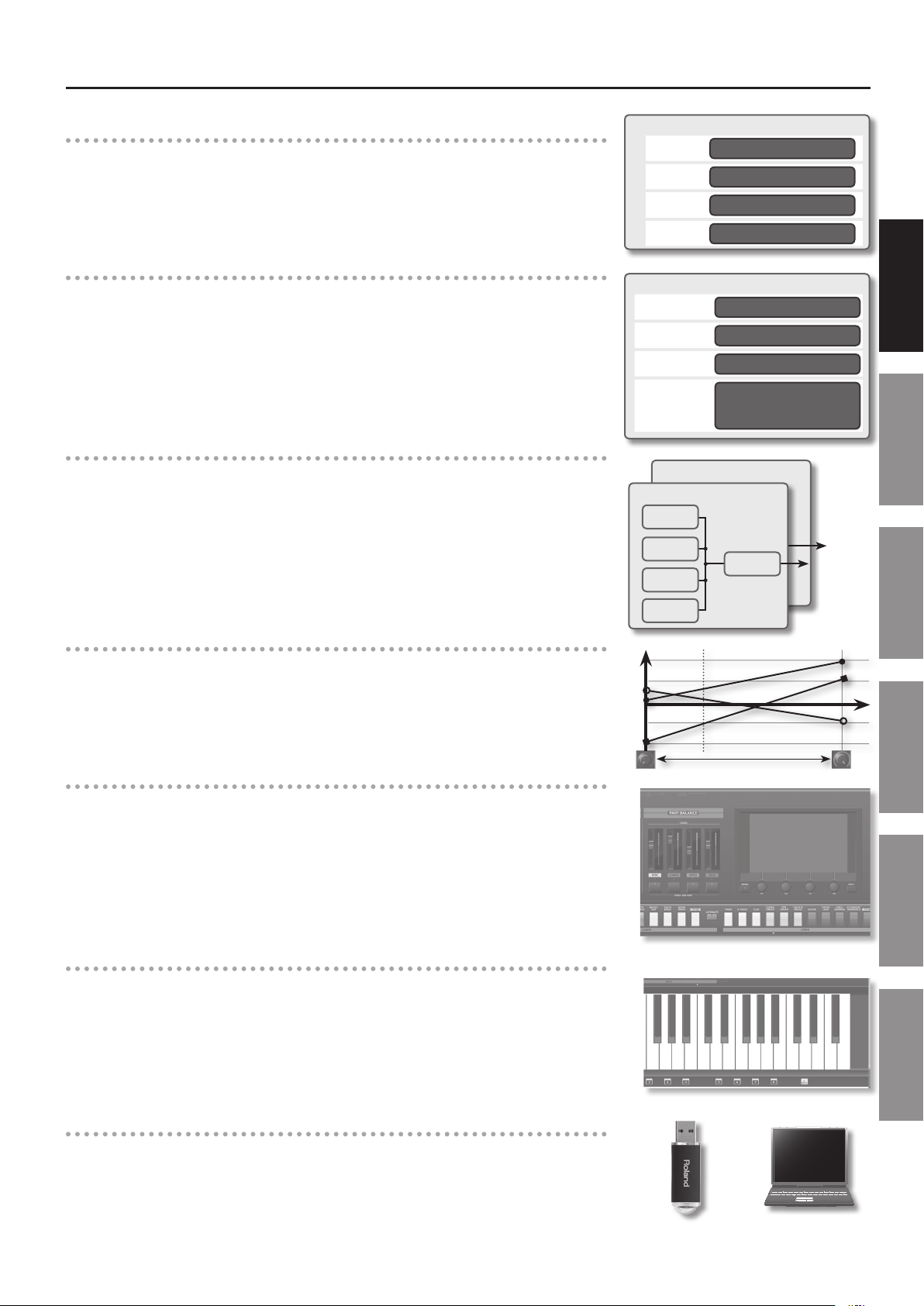
Powerful Live Sets with SuperNATURAL x 4
The JUPITER-80 can handle up to four SuperNATURAL tones layered as a “Live Set,” letting you
perform with awesome and richly expressive sounds.
In addition, you can assign Live Sets to the Upper and Lower Parts to create splits and layers,
making it easy to construct rich-sounding stacks that were dicult to obtain on a single
conventional synthesizer.
Four-part Registrations for Extensive Performance Potential
In addition to the Upper Part and Lower Part that are the core of your performance, the
JUPITER-80 provides a Solo Part that lets you play a melody or solo on the top note, and a
Percussion Part that spices up your performance.
All of these together can be instantly called up by pressing a Registration button.
Powerful Sound with a Full Selection of Eects
A Live Set contains four multi-eects (MFX) processors in parallel, each giving you a choice of 76
types of eects that range from standard sounds to eects that powerfully transform your sound.
In addition to this, the Live Set also provides a reverb processor.
By using the Upper Part and Lower Part simultaneously, you can create powerful sounds that use
up to eight eects and two reverbs simultaneously.
The Solo Part and the Percussion Part also have their own independent compressor, EQ, and delay,
and both the Solo Part and Percussion Part also each have their own reverb.
Live Set
Layer 1
Layer 2
Layer 3
Layer 4
Registration (Part)
Upper
Lower
Solo
Percussion
Upper Part
Lower Part
MFX 1
MFX 2
MFX 3
SuperNATURAL Tone
SuperNATURAL Tone
SuperNATURAL Tone
SuperNATURAL Tone
Introduction Playing Sounds Editing Sounds
SuperNATURAL Tone x 4
SuperNATURAL Tone x 4
SuperNATURAL Tone x 4
SuperNATURAL Tone x 4
or
Tone (Perc) x1
Reverb
Tone Blender
A Live Set features the new Tone Blender function, which lets you simultaneously control multiple
parameters such as the level, pan, cuto, and MFX send for each of the four tones.
By using a knob or the D Beam to simultaneously control multiple parameters of four tones in the
Live Set, you can easily generate powerful sonic transformations that were impossible on previous
synthesizers (p. 61).
Controllers Optimized for Live Performance
A color-coded panel layout and full-color TFT touch screen (pressure sensitive) ensure that the
status of the sound is instantly comprehensible.
Dedicated buttons are provided for instant access to the functions you need, guaranteeing
intuitive operation during your live performances. In addition, the JUPITER-80 provides four sliders
with LED meters that allow you to directly adjust each Part’s volume at any time, a modulation
lever for expressive dynamics, [S1] and [S2] buttons for switching between performance
techniques, and a D Beam controller for additional performance possibilities—all focused on
realtime playability.
Sturdy Body and a 76-note Weighted Keyboard
The keyboard is the most important factor in your performance, and the JUPITER-80 provides a
weighted 76-note keyboard that gives you superb playing feel for condent performances on
stage.
Coupled with the sturdy aluminum-paneled body, this is a keyboard that expressively responds to
every nuance of your playing.
MFX 4
Other Convenient
Functions
Connecting Other
Equipment
Appendix
USB Audio Player/Recorder
USB MIDI/AUDIO Support
The built-in Audio Recorder provides a great way to capture your phrases and inspirations on a
USB ash drive as audio les (WAV). Of course, audio les (WAV, AIFF, MP3) can also be played back
from your USB ash drive, allowing you to use them as backing tracks for your performance.
The JUPITER-80 also provides a USB MIDI/AUDIO connection to your computer. Even when you’re
in your production studio, you’ll enjoy the same familiar setup as when performing live.
11
Page 12

Getting Acquainted with the JUPITER-80
How the Sound Generator is Organized
The sound generator is organized into units of sounds called “Registrations,” “Live Sets,” and “tones.”
The JUPITER-80’s sound generator
Registration
Solo Part
Tone
Upper Part
Live Set
Tone 1
Tone 2
Tone 3
Tone 4
Lower Part
Live Set
Tone 1
Tone 2
Tone 3
Equalizer
MFX 1
MFX 2
MFX 3
MFX 4
MFX 1
MFX 2
MFX 3
Delay
Reverb
Reverb
Audio data ow Performance data ow
ReverbComp
MASTER
EQ
Harmony
Intelligence
Arpeggio
Tone 4
Percussion Part
Tone 4
Comp
MFX 4
Equalizer
Delay
What is a Tone?
Although a Tone is the smallest unit of sound handled by the JUPITER-80, it boasts an extravagantly powerful structure based on SuperNATURAL
sounds. “SuperNATURAL Acoustic Tones” not only reproduce the sounds of an acoustic instrument, but also automatically analyze—in a way
that’s appropriate for each dierent tone—the dierences between the phrases, chords, and melodies played by the performer, and deliver the
responsiveness that is characteristic of that specic acoustic instrument. Starting with the SuperNATURAL piano, each of these sounds brings you the
highest possible level of expressive power that has been developed for the sound engines of earlier Roland products.
“SuperNATURAL Synth Tones” can be combined as elements in a Live Set, and can also be edited in detail for each tone and saved. Since a single Synth
Tone contains three sets of oscillator, lter, amp, and LFO, it packs a formidable amount of synthesis power. The oscillator contains not only analog
waveforms but also PCM waveforms, and you can use the graphic screen to edit them intuitively, creating a nearly innite range of synth sounds.
What is a Live Set?
In the JUPITER-80’s sound engine, the smallest unit of sound is the “tone”; each tone consists of a SuperNATURAL sound.
Up to four tones can be layered to create impressive and richly expressive sounds.
Such a combination can be saved as a “Live Set,” and a dierent Live Set can be used for the Upper Part and the Lower Part.
By layering two Live Sets, you can easily create thick, stacked sounds that would have been dicult to create on any previous PCM synthesizer.
The basic method of creating sound on the JUPITER-80 is to edit a Live Set by combining these powerful tones.
What is a Registration?
The combination of sounds assigned to the Upper Part, Lower Part, Solo Part, and Percussion Part, together with settings for the JUPITER-80 itself, can
be saved as a single “Registration.”
A Registration can be called up instantly, allowing you to switch sounds as appropriate for the song you’re playing, or to instantly get the settings you
need for live performance or studio recording.
12
Page 13
Getting Acquainted with the JUPITER-80
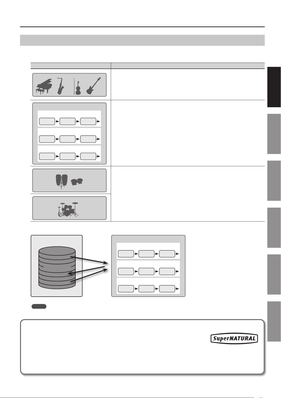
Tones
The “tone” is the smallest unit of sound that is managed on the JUPITER-80.
There are four types of tones, as shown in the table below. These tones are the elements that make up Registrations (p. 15) and Live Sets (p. 14).
Type Explanation
SuperNATURAL Acoustic Tone
SuperNATURAL Synth Tone
Partial 1
OSC FILTER AMP
Partial 2
OSC FILTER AMP
Partial 3
OSC FILTER AMP
These are acoustic-type SuperNATURAL sounds.
Many realistic sounds using Behavior Modeling Technology are provided.
You can also use the Live Set Tone Modify screen (p. 32, p. 78) to adjust certain parameters that have been selected
as most appropriate for each sound.
These tones can be assigned to a Live Set (Upper Part, Lower Part), to the Solo Part, or to the Percussion Part.
These are synthesizer-type SuperNATURAL sounds.
These tones allow you to freely create original sounds, as on an analog synthesizer (p. 66).
One tone can produce the sound of three synthesizers, each with an oscillator (OSC), lter (FILTER), and
amplier (AMP).
The oscillator (OSC) provides not only the waveforms of a standard analog synthesizer, but also PCM
waveforms.
You can save 2,048 tones you’ve edited (p. 68).
These tones can be assigned to the Live Set (Upper Part, Lower Part), Solo Part, and Percussion Part.
Introduction Playing Sounds Editing Sounds
Manual Percussion
These produce the sounds of percussion instruments or sound eects.
A wide variety of percussion instruments and sound eects will be heard depending on the key (note number)
you play.
Drums/SFX
These tones can be assigned only to the Percussion Part.
You can save 2,048 SuperNATURAL Synth Tones you’ve edited, and call them up when desired.
SuperNATURAL Synth Tone
Partial 1
OSC FILTER AMP
Partial 2
0001–2048
OSC FILTER AMP
Partial 3
OSC FILTER AMP
MEMO
The results of your editing a SuperNATURAL Acoustic Tone, Manual Percussion, and Drums/SFX can be saved as a Registration or as a Live Set.
Other Convenient
Functions
Connecting Other
Equipment
Appendix
What are SuperNATURAL Tones?
Taking advantage of Behavior Modeling Technology, SuperNATURAL is Roland’s exclusive sound set
that achieves a new level of realism and expression that were dicult to realize with previous sound
generators.
Behavior Modeling Technology
Not only physical modeling of the instruments, Roland takes it a step further by modeling the instrument’s distinctive behavior that responds
to how the performer plays, resulting in true-to-life, expressive sounds in realtime.
13
Page 14
Getting Acquainted with the JUPITER-80
Live Sets
A Live Set consists of the Tones assigned to the four layers, settings
for four MFX units, and settings for one reverb unit.
Live Set
Layer 1
Layer 2
Layer 3
Layer 4
You can select a Live Set as the sound for the Upper Part, and
another Live Set as the sound for the Lower Part.
You can save 2,560 Live Sets you’ve edited, then call them up when
desired.
Tone 1
Tone 2
Tone 3
Tone 4
0001–2560
MFX 1
MFX 2
Reverb
MFX 3
MFX 4
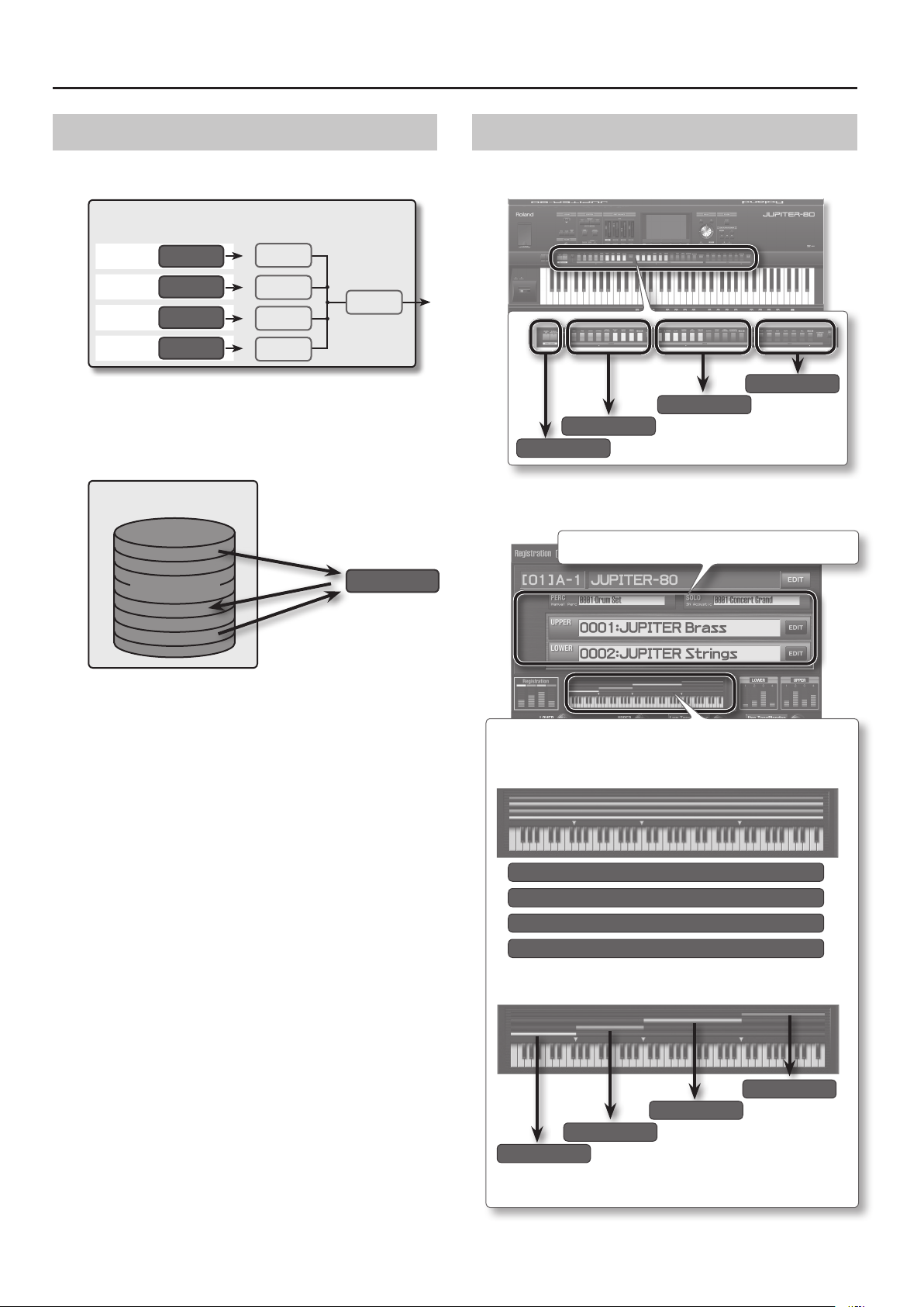
Parts
The JUPITER-80 has four parts; Solo, Upper, Lower, and Percussion.
You can assign a Tone or Live Set to each Part and play it.
Solo
Upper
Lower
Percussion
You can play all Parts from the same keys, or use the Split function
(p. 39) to divide the keyboard and assign the sounds of dierent Parts
to their own zones.
The Registration screen shows the name of each Part’s sound.
Live Set
Edits you make to the parameters of a Live Set are relative
adjustments that increase or decrease the values of the Tones; they
do not directly modify the Tones themselves.
This means that even if the same tone is used in other Live Sets, the
other Live Sets will not be aected by your editing.
This shows the split status of the Parts.
Not split
Solo
Upper
Lower
Percussion
Split
Solo
Upper
Lower
Percussion
14
For details on split, refer to “Split Performance” (p. 39).
Page 15
Getting Acquainted with the JUPITER-80
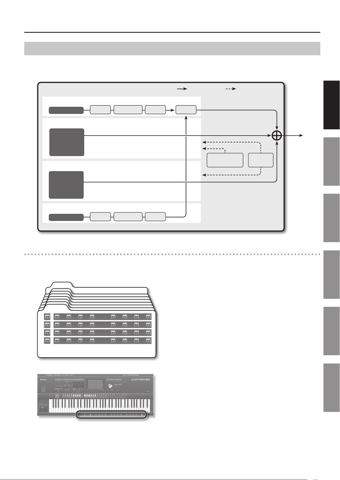
Registrations
A Registration consists of these four Parts: Solo, Upper, Lower, and Percussion.
Stored within a Registration are the settings for the sound selected for each Part, as well as settings for the Solo Part and Percussion Part.
By switching Registrations, you can change all of these settings at once (except for the system parameters).
Registration
Solo Part
Tone
Upper Part
Live Set
Lower Part
Live Set
Percussion Part
Tone
Comp
Equalizer
Equalizer
Delay
Delay
Audio data ow Performance data ow
ReverbComp
How Registrations are Organized
Registrations are managed in “banks” of eight. In turn, these banks are managed as “sets” of four banks.
Since there are eight sets, 8 Registrations x 4 banks x 8 sets makes a total of 256 Registrations.
Harmony
Intelligence
Introduction Playing Sounds Editing Sounds
Arpeggio
Other Convenient
Functions
Bank 8
Bank 1
Bank
(A–D)
The sounds and settings saved in a Registration can be called up at the touch of a button (p. 41).
Registration (1–8)
Connecting Other
Equipment
Appendix
15
Page 16

Getting Acquainted with the JUPITER-80
About Memory
The area in which sounds and other settings are stored is called “memory.”
Memory is divided into three areas: temporary memory (the temporary area), rewritable memory, and non-rewritable memory.
JUPITER-80
Temporary Area
Select
Non-rewritable Memory
SuperNATURAL
Acoustic Tones
Manual Percussions
Drums/SFX
Preset Arpeggio Styles
User Arpeggio Styles (128)
Restore
USB Flash Drive
ROLAND Folder
User Arpeggio Styles (128)
Select Write
Rewritable Memory
Registrations (256)
Live Sets (2,560)
SuperNATURAL
Synth Tones (2,048)
Registrations (256)
Live Sets (2,560)
SuperNATURAL
Synth Tones (2,048)
System
Settings
Backup
System
Settings
Temporary Memory (the Temporary Area)
The data for a sound you select is called into this area.
When you play the keyboard, the sounds you hear are produced
according to the settings in the temporary area.
When you edit sounds, you’re editing the data that’s in the
temporary area.
Settings in the temporary area are temporary; they will be lost
when you turn o the power or select other settings.
If you want to keep the settings of the temporary area, you must
save them to rewritable memory.
MEMO
When you import an SMF (Standard MIDI File) as a user arpeggio
style (p. 45), the data is imported directly into rewritable memory;
it does not pass through the temporary area.
Rewritable Memory
This is where you can save Registrations, Live Sets, SuperNATURAL
Synth Tones, user arpeggio styles, and system settings (system
parameters).
Non-rewritable Memory
This contains SuperNATURAL Acoustic Tones, Manual Percussion,
Drums/SFX, and preset arpeggio style data.
This data cannot be directly rewritten; however, you are free to save
the edited results in a Registration or Live Set.
USB Flash Drive
The data saved in rewritable memory can be backed up to a USB
ash drive (p. 79).
A USB ash drive can contain one set of backup data.
16
Page 17
Getting Acquainted with the JUPITER-80
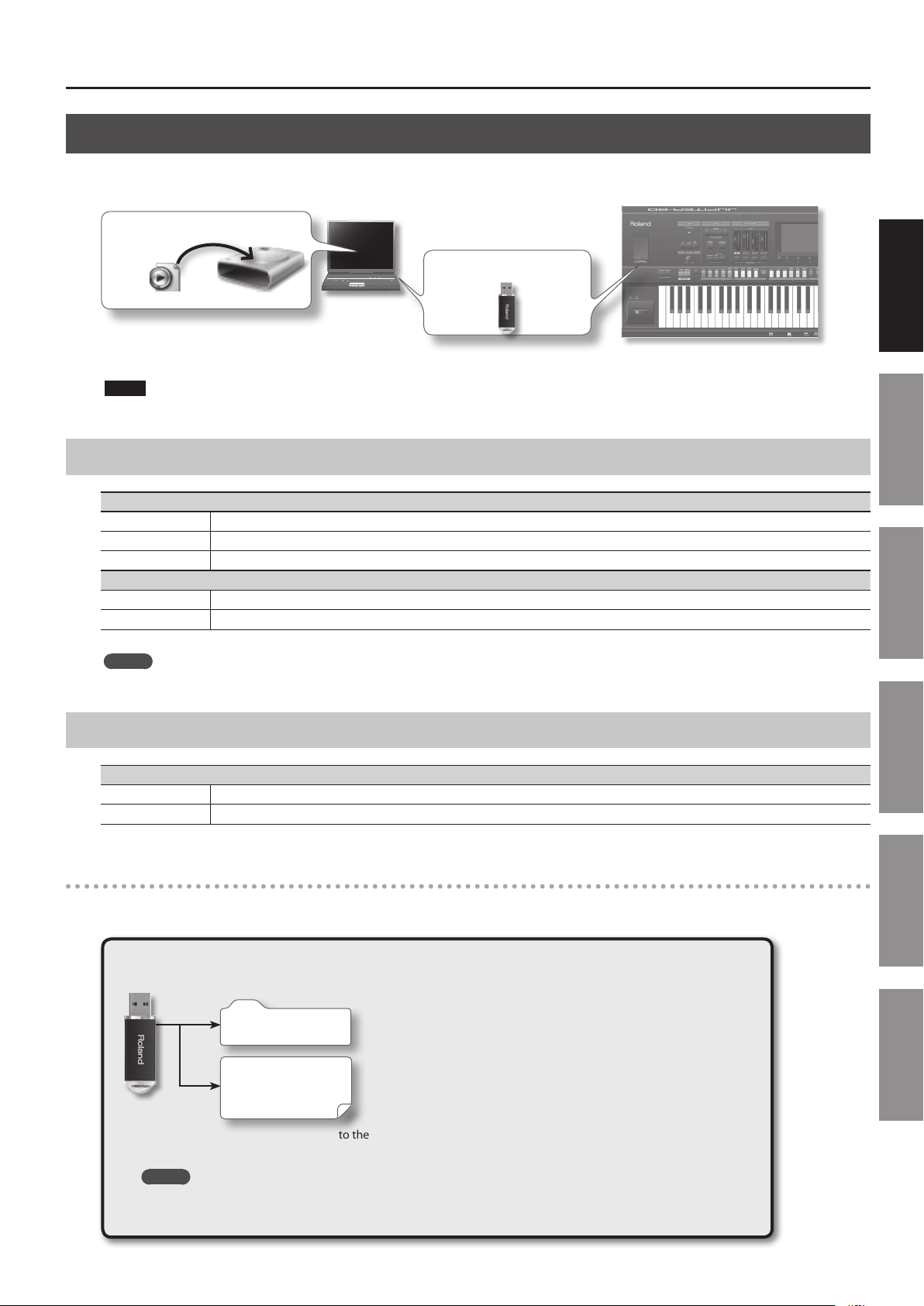
USB Memory Song Player/Recorder
The USB Memory Song Player/Recorder plays back audio les (WAV, MP3, AIFF) that you’ve copied from your computer to a USB ash drive.
Copy to a USB Memory
Insert USB Memory
MP3/WAV/AIFF
You can also record the JUPITER-80’s performance and save it on a USB ash drive as a WAV le.
NOTE
Use USB Flash Memory sold by Roland. We cannot guarantee operation if other products are used.
Audio les that can be played
MP3
Format MPEG-1 audio layer 3
Sampling Frequency 44.1 kHz
Bit Rate 32k, 40k, 48k, 56k, 64k, 80k, 96k, 112k, 128k, 160k, 192k, 224k, 256k, 320 kbps / VBR (Variable Bit Rate)
WAV/AIFF
Sampling Frequency 44.1 kHz, 48 kHz, 96 kHz
Bit 8, 16, 24-bit
Introduction Playing Sounds Editing Sounds
MEMO
Use only single-byte alphanumeric characters in le names and folder names.
Audio les that will be saved
WAV
Sampling Frequency 44.1kHz
Bit Rate 16-bit
Data Saved in USB Flash Drive
A USB ash drive can hold audio les, MIDI les that you want to import as user arpeggio styles, and the JUPITER-80’s internal memory data that
you’ve backed up.
USB Flash Drive
ROLAND Folder
Audio Files
MIDI Files
:
This folder is created when you make a backup (p. 79).
This contains the backup le for the JUPITER-80’s internal memory.
WAVE les created by the USB memory song player/recorder and audio les or
MIDI les copied from your computer are saved here.
Other Convenient
Functions
Connecting Other
Equipment
Appendix
Copy your audio les (WAV, MP3, AIFF) to the root folder (the top level) of your USB ash drive, or create a folder
on your USB ash drive and copy the les into it.
MEMO
• Use only single-byte alphanumeric characters in le names and folder names.
• A maximum of 200 les can be recognized in a folder.
17
Page 18
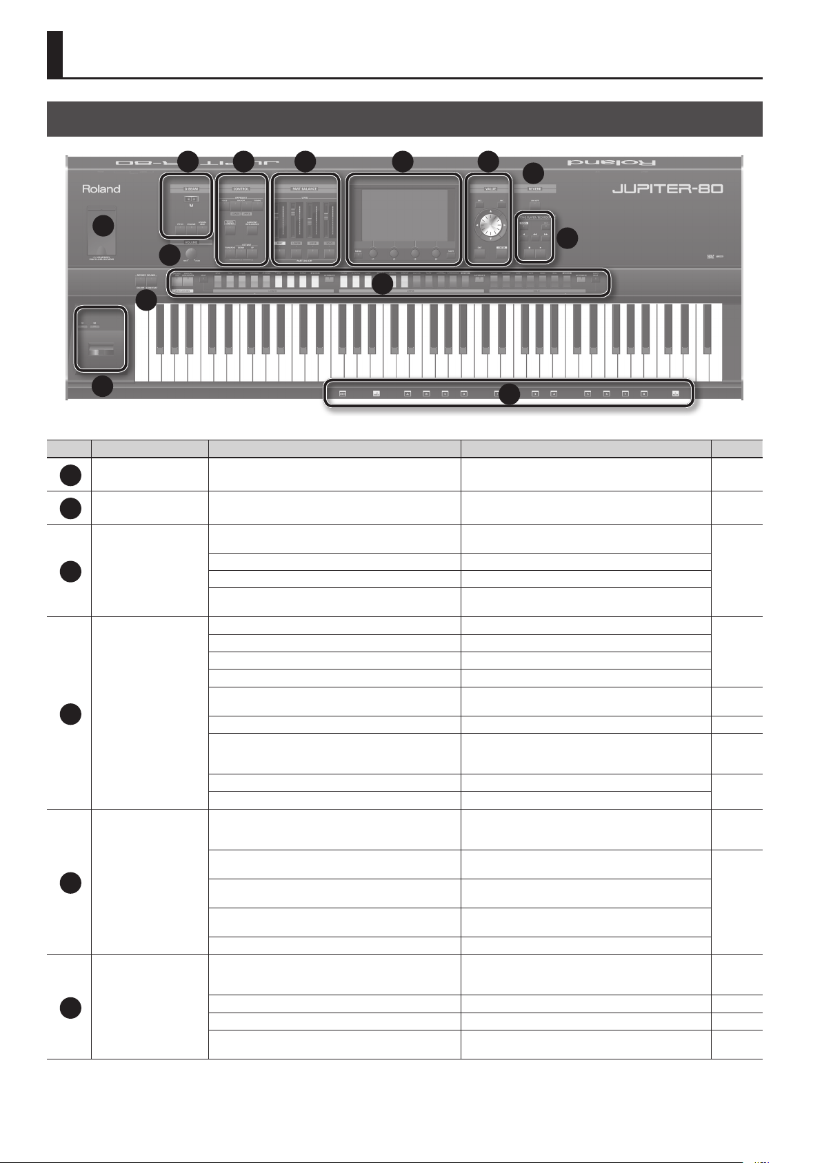
Panel Descriptions
Top Panel
3
4 75 6
8
1
9
2
11
10
12
Number Area Name Explanation Page
USB MEMORY USB MEMORY connector Connect USB ash memory (available separately) here. p. 17
1
VOLUME [VOLUME] knob
2
D Beam controller
3
4
5
6
D BEAM
CONTROL
PART BALANCE
Display
[PITCH] button If this is on, the D Beam controller will control the pitch.
[VOLUME] button If this is on, the D Beam controller will control the volume.
[ASSIGNABLE] button
[HOLD] button Turns the arpeggiator Hold function on/o.
ARPEGGIO [LOWER ON/OFF] button If this is on, the arpeggiator will apply to the Lower Part.
ARPEGGIO [UPPER ON/OFF] button If this is on, the arpeggiator will apply to the Upper Part.
[TEMPO] button Accesses the tempo screen.
[VISUAL CONTROL] button
[HARMONY INTELLIGENCE] button Turns the Harmony Intelligence function on/o. p. 46
[TRANSPOSE] button
OCTAVE [DOWN] button Lowers the key range in steps of one octave.
OCTAVE [UP] button Raises the key range in steps of one octave.
[LEVEL] slider
PART [PERC] button
PART [LOWER] button
PART [UPPER] button
PART [SOLO] button Turns the Solo Part or Live Set layer 4 on/o.
Touch screen
[MENU] button Accesses the MENU screen. p. 29
[E1]–[E4] knobs Edit the values of the parameters shown in the display. p. 26
[SHIFT] button
13
Adjusts the volume of the output from the MAIN OUT jacks
and PHONES jack.
By moving your hand above the D Beam you can apply
various eects to the sound.
If this is on, the D Beam controller will control the function
you’ve assigned.
Turns MIDI Visual Control on/o. When you press this button
to turn it on, the setting screen will appear.
By holding down the [TRANSPOSE] button and using the
[-] [+] buttons, you can transpose the keyboard in semitone
steps.
Adjust the volume of each Part, or the volume of each layer
in the Live Set. For a SuperNATURAL Synth Tone, these adjust
the AMP level of each Partial.
Turns the Percussion Part, the Live Set layer 1, or a
SuperNATURAL Synth Tone’s Partial 1 on/o.
Turns the Lower Part, the Live Set layer 2, or a SuperNATURAL Synth Tone’s Partial 2 on/o.
Turns the Upper Part, the Live Set layer 3, or a SuperNATURAL Synth Tone’s Partial 3 on/o.
Shows various information for the operation you’re
performing, and allows you to control parameters by directly
touching the screen.
This is used in conjunction with other buttons to access
setting screens related to those buttons.
p. 23
p. 47
p. 43
p. 95
p. 50
p. 50
p. 37, p. 58,
p. 67
p. 37, p. 58,
p. 67
p. 27, p. 30–
p. 28
18
Page 19

Panel Descriptions
Number Area Name Explanation Page
Use these buttons to edit values. To make the change occur
[DEC]/[INC] buttons
[
][ ][ ][ ] (Cursor) buttons
VALUE
7
REVERB REVERB [ON/OFF] button
8
SONG PLAYER/RECORDER
9
ROTARY SOUND
10
Selecting tones for Parts
11
Controller
12
Registration
13
Value dial
[EXIT] button
[ENTER] button
[SONG] button Accesses the Song screen. p. 72
[REC] button
[
] button
[
[
] button
[
[
] button
ROTARY SOUND [ON/OFF] button
ROTARY SOUND [SLOW/FAST ] button Switches the speaker rotation speed between Slow and Fast.
PERCUSSION Tone button Select the Tone for the Percussion Part.
Live Set LOWER button Select the Live Set for the Lower Part.
Live Set UPPER button Select the Live Set for the Upper Part.
SOLO Tone button Select the Tone for the Solo Part.
LOWER [ALTERNATE] button
UPPER [ALTERNATE] button
SOLO [ALTERNATE] button
[SPLIT] button
[SOLO SPLIT] button
[S1], [S2] buttons
Pitch Bend/Modulation Lever Modies the pitch, applies vibrato, etc. p. 47
[WRITE] button Accesses the Registration Write screen. p. 53
[PREV] button Calls up the previous Registration or Registration Set.
Registration Bank buttons ([A]–[D]) Select the Registration Bank.
Registration buttons ([1]–[8]) Select a Registration.
[NEXT] button Calls up the next Registration or Registration Set.
] button
] button
more rapidly, hold down one button and press the opposite
button. You can also make the value change rapidly by
holding down the [SHIFT] button and pressing one of these
buttons.
Move the cursor up/down/left/right. p. 24
Use this to edit values. To make the value change rapidly,
operate the value dial while holding down the [SHIFT]
button.
Returns you to the previous screen, or closes the currently
open window. In some screens, this button cancels the
function you were executing.
Conrms a value or executes an operation. This button also
displays a list of Live Sets or tones.
Simultaneously turns on/o the output of the Live
Set’s reverb and the reverb shared by the Solo Part and
Percussion Part.
Selects recording-standby mode. Next, press the [
button to start recording.
Returns to the beginning of the audio le.
Rewinds the audio le while you hold down the button.
Fast-forwards the audio le while you hold down the button.
Stops audio le playback or recording.
Plays back the audio le.
Turns on/o the rotary eect assigned to the MFX of the
Live Set.
These buttons call up dierent sounds that are similar to the
sounds of the Part sound buttons.
Splits the keyboard. Keys to the left of the Lower Split
Point will play only the sounds of the Lower Part and the
Percussion Part.
Splits the keyboard. Keys to the right of the Solo Split Point
will play only the sound of the Solo Part.
Convenient performance functions can be assigned to these
buttons.
p. 25
p. 25
–
–
p. 49
]
p. 77
p. 72
p. 49
p. 36
p. 39
p. 47
p. 41
Introduction Playing Sounds Editing Sounds
Other Convenient
Functions
Connecting Other
Equipment
19
Appendix
Page 20
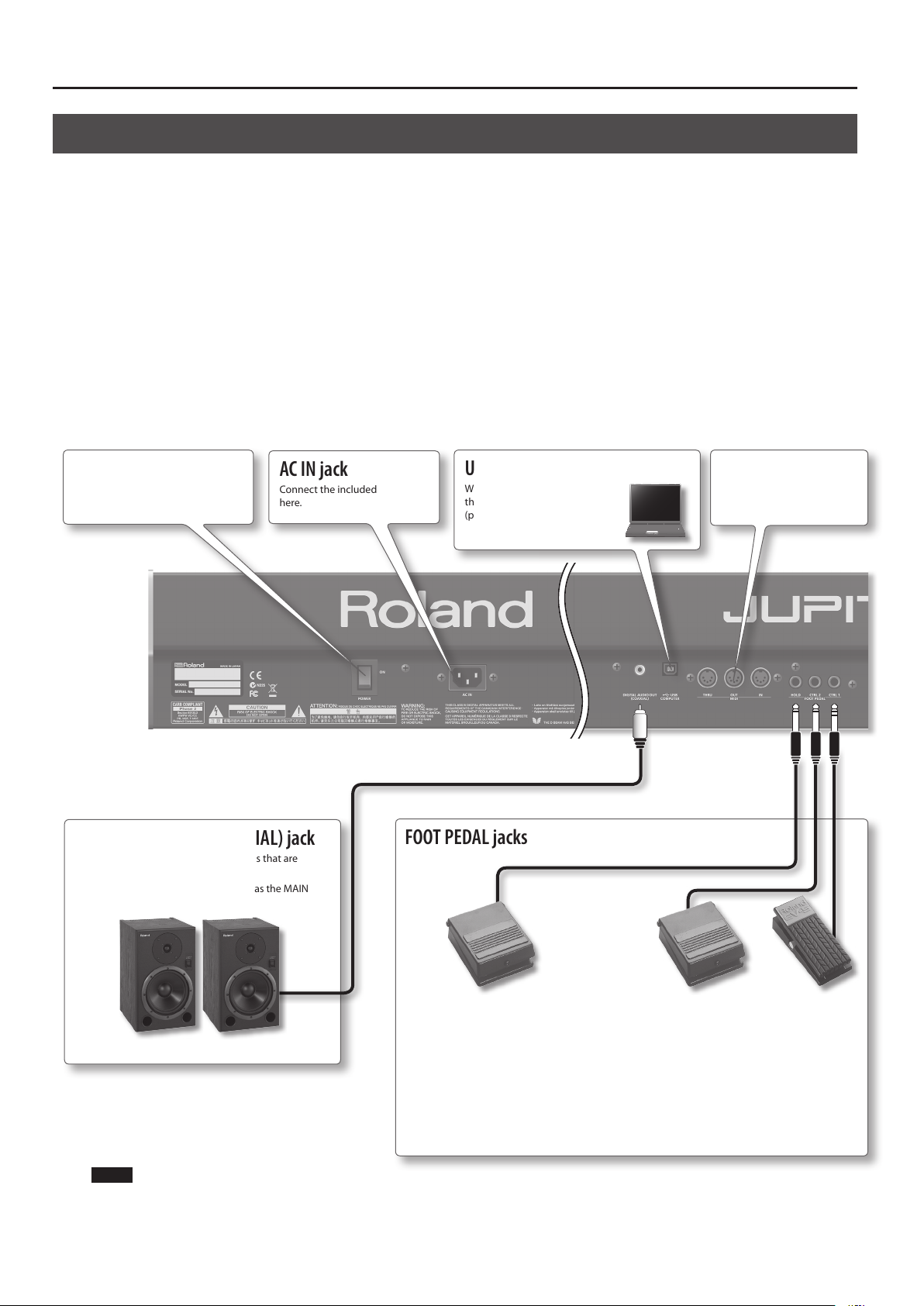
Panel Descriptions
Rear Panel Connections
[POWER] switch
This turns the power on/o (“Turning
the Power On” (p. 23).
AC IN jack
Connect the included AC cord
here.
DIGITAL AUDIO OUT (COAXIAL) jack
Connect this to speakers or other devices that are
equipped with a digital input.
This jack outputs the same audio signal as the MAIN
OUT jacks.
USB COMPUTER connector
With a USB cable, you can connect
the JUPITER-80 to your computer
(p. 90).
FOOT PEDAL jacks
MIDI connectors
For connecting MIDI device
(p. 91).
20
Hold jack
Here you can connect a pedal
switch (such as one from the DP
series; sold separately) and use it
as a Hold pedal (p. 48).
NOTE
To prevent malfunction and/or damage to speakers or other devices, always turn down the volume, and turn o the power on all devices before
making any connections.
CTRL 1, CTRL 2 jacks
Here you can connect an expression pedal (EV-5; sold
separately) and use it to control various parameters or
functions (p. 48).
* Use only the specied expression pedal (EV-5; sold
separately). By connecting any other expression
pedals, you risk causing malfunction and/or
damage to the unit.
Page 21

Panel Descriptions
1: GND2: HOT
1: GND 2: HOT
1: GND
3: COLD
SUB OUT jacks
You can connect speakers here for use as monitors,
or for outputting only the reverb sound. The system
setting “Output Assign” (p. 86) species which sounds
will be output from the SUB OUT jacks.
* The [VOLUME] knob on the top panel does not
adjust the volume of these jacks.
MAIN OUT (TRS) jacks
Connect your speakers here. To employ monaural
output, connect to the L/MONO jack.
This instrument is equipped with balanced (XLR/TRS) type jacks. Wiring diagrams for these jacks are
shown below. Make connections after rst checking the wiring diagrams of other equipment you
intend to connect.
TIP: HOT
RING: COLD
SLEEVE: GND
MAIN OUT (XLR) jacks
These are balanced output jacks for audio signals.
Connect them to your mixer.
Introduction Playing Sounds Editing Sounds
2: HOT
AUDIO IN (STEREO) jack
Connect your digital audio player or audio playback device here.
Use a stereo mini-plug cable (commercially available) to make the
connection.
The input level is adjusted by the [LEVEL] knob located at the left of the jack.
PHONES jack
You can connect a set of headphones
(sold separately) here.
Other Convenient
Functions
Connecting Other
Equipment
Appendix
21
Page 22
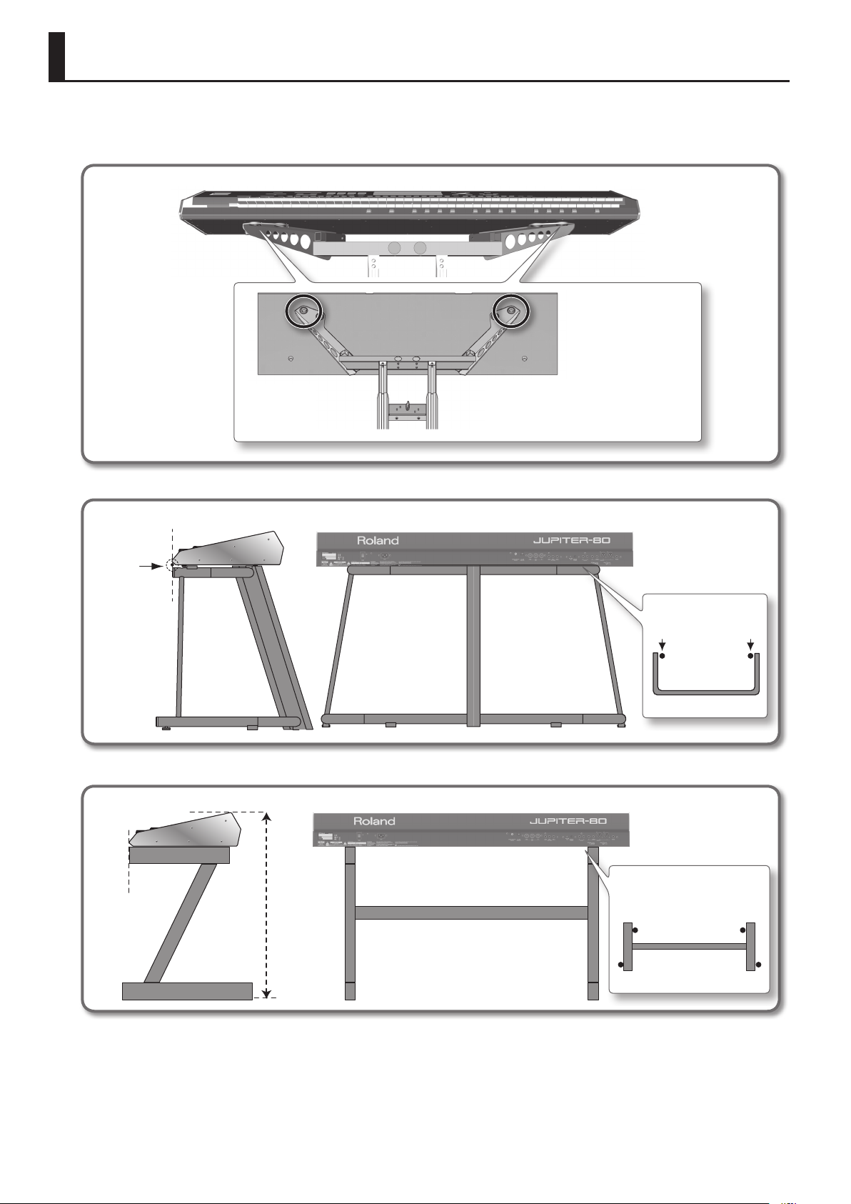
Placing the JUPITER-80 on a Stand
Be careful not to pinch your ngers when setting up the stand.
If you want to place the JUPITER-80 on a stand, use the Roland KS-J8, KS-G8, or KS-18Z.
Place the instrument on the stand as follows.
KS-J8
Firmly insert the rubber
feet on the bottom of
the keyboard (at its
front, beneath the keys)
into the rubber feet
receptacles on the arms.
KS-G8
Align the front of
the JUPITER-80
with the front of
the stand
KS-18Z
Align the front of the
JUPITER-80 with the
front of the stand
Adjust so that
the height does
not exceed 1
meter (Adjust
the stand to a
level no higher
than the fourth
level from the
bottom)
Place the JUPITER-80 so
that it’s rubber feet are in
the inner side of the stand
Top view
Adjust the width of the stand
so that the rubber feet of the
JUPITER-80 straddle the stand
Top view
22
Page 23
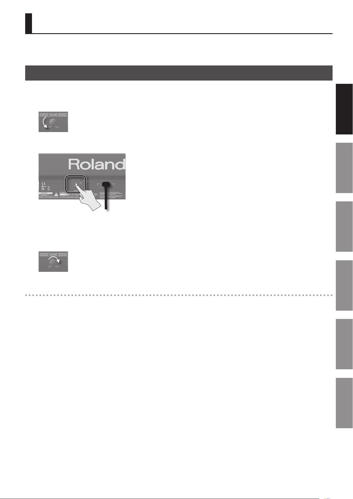
Turning the Power On
Once the connections have been completed (p. 20), turn on power to your various devices in the order specied. By turning on devices in the wrong
order, you risk causing malfunction and/or damage to speakers and other devices.
Turning the Power On
Turning the Power On
* Before switching the power on/o, always be sure to turn the volume down. Even with the volume turned down, you might hear some sound
when switching the power on/o (p. 5). However, this is normal and does not indicate a malfunction.
1. Minimize the volume of the JUPITER-80 and your speakers.
2. On the JUPITER-80’s rear panel, turn the [POWER] switch ON.
Introduction Playing Sounds Editing Sounds
* This unit is equipped with a protection circuit. A brief interval (a few seconds) after power up is required before the unit will operate normally.
3. Turn on the power of your speakers.
4. Use the [VOLUME] knob to adjust the volume appropriately.
Turning the Power O
1. Minimize the volume of the JUPITER-80 and your speakers.
2. Turn o the power of your speakers.
3. Turn the JUPITER-80’s [POWER] switch OFF.
If you need to turn o the power completely, rst turn o the POWER switch, then unplug the power cord from the “Power Supply” (p. 5).
Other Convenient
Functions
Connecting Other
Equipment
Appendix
23
Page 24
Basic Operation
This section explains the basic button and knob operations used to operate the JUPITER-80.
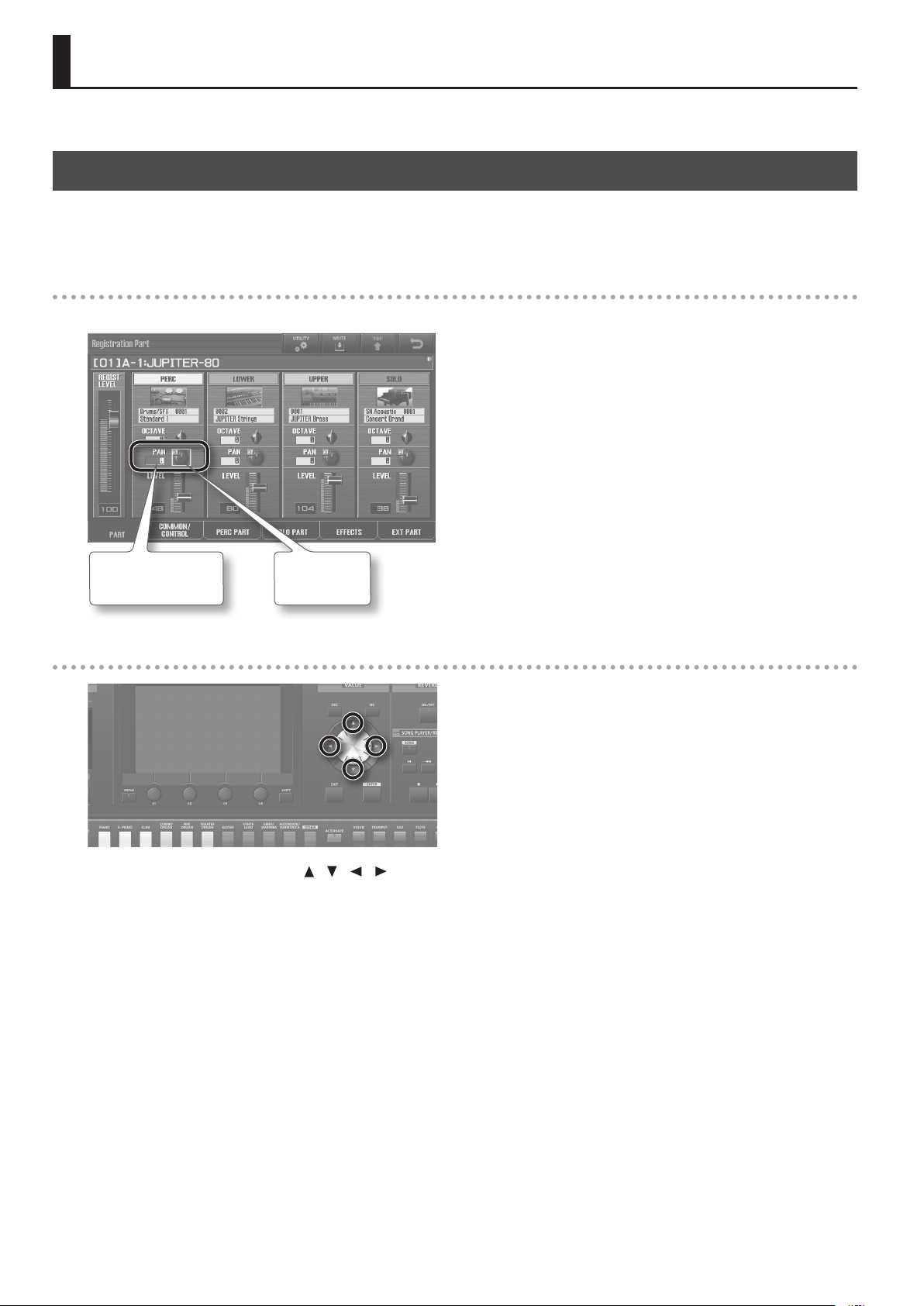
Moving the Cursor
A single screen or window will contain multiple items (parameters) to edit or select. To edit a parameter’s setting, you must rst move the cursor to
that parameter’s value.
The value of the selected parameter is highlighted in blue, and the knob or slider is indicated by a green frame.
Touch panel
To move the cursor, simply touch a parameter value, knob, or slider.
Cursor
(highlighted blue)
Cursor
(green frame)
Cursor buttons
You can move the cursor by pressing the [ ] [ ] [ ] [ ] (cursor) buttons.
If you hold down a cursor button, the cursor will continue moving.
If you hold down the cursor button for the desired direction, and then press the opposite cursor button, the cursor will move more quickly.
24
Page 25
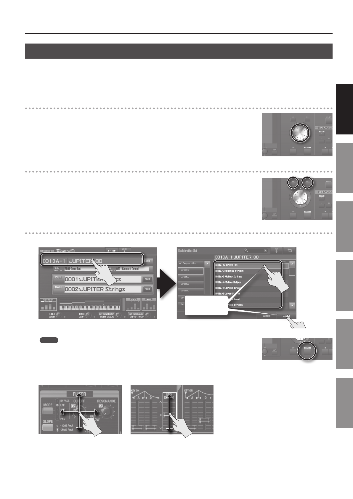
Editing a Value
To edit the value highlighted by the cursor, use either of the following controllers.
• Value dial
• [DEC] [INC] buttons
• Touch panel
Value dial
Turning the value dial toward the right will increase the value, and turning it toward the left will decrease the
value.
If you hold down the [SHIFT] button while turning the value dial, the value will change in larger steps.
[DEC] [INC] buttons
Press the [INC] button to increase the value, or press the [DEC] button to decrease the value.
• If you hold down a button, the value will increase (or decrease) continuously.
• To rapidly increase the value, hold down the [INC] button and press the [DEC] button. Conversely, to rapidly
decrease the value, hold down the [DEC] button and press the [INC] button.
• If you hold down the [SHIFT] button and press the [INC] button or [DEC] button, the value will change in
larger steps.
Basic Operation
Introduction Playing Sounds Editing Sounds
Touch panel
When you touch the eld highlighted by the cursor, a list of the available selections for that item will appear.
Select an item and
touch <Select>.
MEMO
Instead of touching the eld highlighted by the cursor, you can press the [ENTER] button to view a list.
If an on-screen knob or slider is enclosed in a green frame (i.e., is selected), you can drag your nger up/down/left/right to edit its value.
Upward or to the right will increase the value, and downward or to the left will decrease the value.
Other Convenient
Functions
Connecting Other
Equipment
Appendix
25
Page 26
Basic Operation
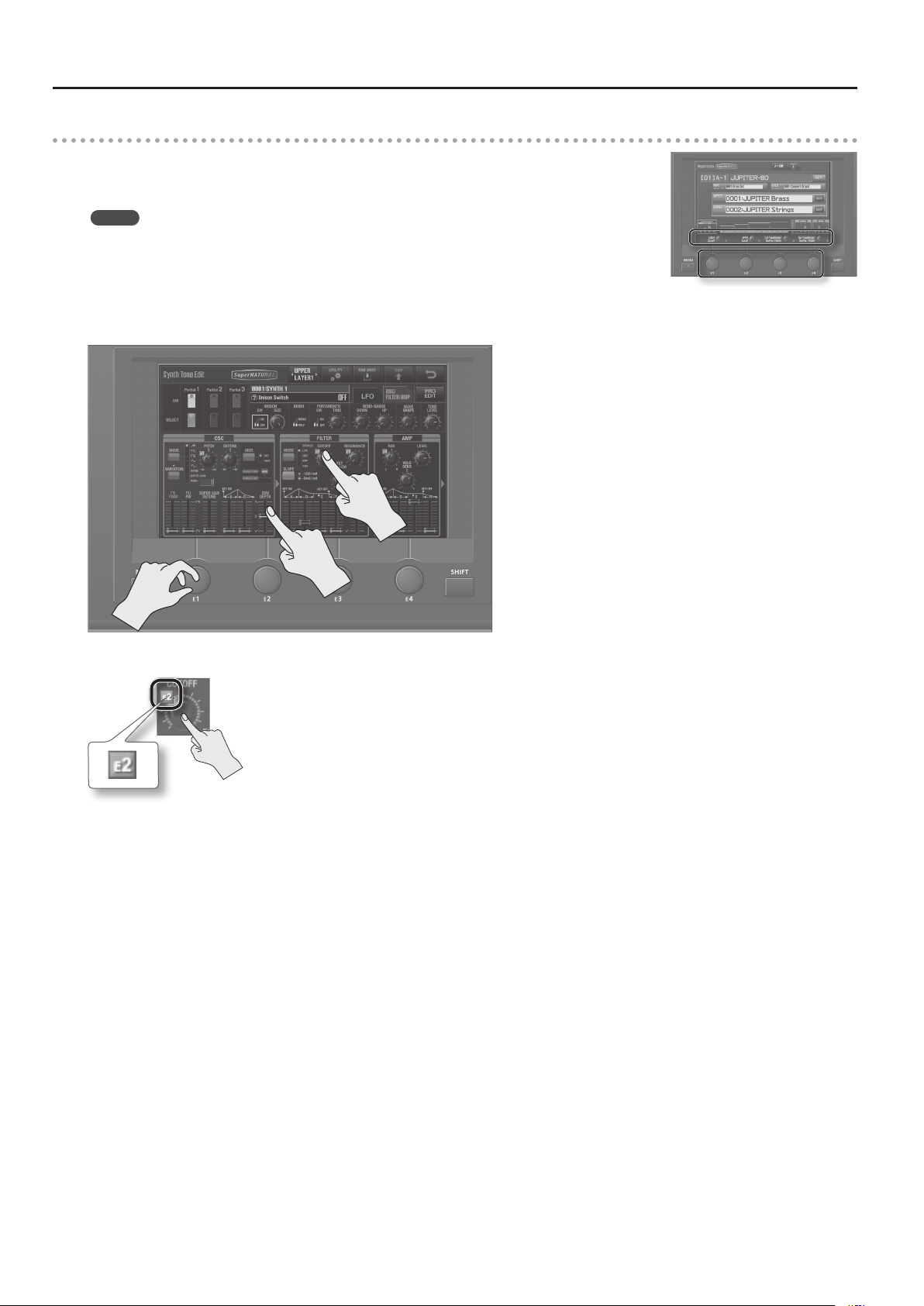
[E1]–[E4] knobs
When knob icons are shown in the Lower Part of the screen, the [E1]–[E4] knobs will change the parameter
values of those knob icons.
MEMO
You can assign performance-related functions to knobs [E1]–[E4]. The functions assigned to knobs [E1]–[E4]
can be specied in the Registration Common/Control screen (p. 52).
If you turn an [E1]–[E4] knob while touching the selected knob or slider (i.e., the one enclosed by the green
frame) in the screen, the parameter you touched will be assigned to the knob you turned.
Now you can edit the value by turning the [E1]–[E4] knob.
The parameters assigned to the [E1]–[E4] knobs are indicated by icons E1–E4.
This operation is available in the following screens.
• Registration Part screen (p. 30)
• Registration Eects Routing screen (p. 31)
• Live Set Eects Routing screen (p. 32)
• Synth Tone Edit screen (p. 33)
26
Page 27

Basic Touch Panel Operation
The JUPITER-80’s display is a touch panel; you can perform a variety of operations by directly touching the display.
Here are the basic rules.
Screen indication Explanation
Basic Operation
Edit
Return
Top
Save
Tempo
Utility
Tab
Displays an edit screen for Registrations or Live Sets.
Returns you to the previous screen. Pressing the [EXIT] button has the same result.
Accesses the Registration screen.
Saves the Registration (p. 53).
Saves the Live Set (p. 62).
Saves the Tone (p. 68).
Saves the system settings (p. 83).
Accesses the tempo setting screen (p. 43).
Displays a context-sensitive menu for each screen.
Switch between edit screens.
Introduction Playing Sounds Editing Sounds
Other Convenient
Functions
Scroll bar/Scroll buttons
Cancel/Select
Search
Drag this up or down to scroll the list.
By pressing the scroll buttons located at the top and bottom of the scroll bar, you can scroll by
one item at a time.
<Cancel> discards the selected content and returns you to the previous screen.
<Select> conrms the selected content. (Pressing the panel [ENTER] button has the same result.)
If you touch this icon when a sound list or the like is displayed, a keyboard will appear. By using
the keyboard to enter a key word, you can narrow down the items shown in the list.
Connecting Other
Equipment
Appendix
27
Page 28

Basic Operation
[SHIFT] Button Operations
By holding down the [SHIFT] button and pressing another button, you can edit the settings of the button you pressed, or access a specic screen
(shortcut).
Shortcut Description Page
[SHIFT] + [ASSIGNABLE] Accesses the D Beam Assign setting screen. p. 52
[SHIFT] + [S1] (or [S2]) Accesses the Switch S1 Assign (or Switch S2 Assign) setting screen. p. 52
[SHIFT] + [HOLD]
[SHIFT] + ARPEGGIO LOWER [ON/OFF]
[SHIFT] + ARPEGGIO UPPER [ON/OFF]
[SHIFT] + [HARMONY INTELLIGENCE] Accesses the Harmony Type setting screen. p. 46
Accesses the arpeggiator setting screen. p. 52
[SHIFT] + [SPLIT] Accesses the Lower Split Point setting screen. p. 52
[SHIFT] + [SOLO SPLIT] Accesses the Solo Split Point setting screen. p. 52
[SHIFT] + LOWER [BASS] Accesses the Synth Tone Edit screen for layer 1 of the Live Set assigned to the Lower Part.
[SHIFT] + LOWER [PAD] Accesses the Synth Tone Edit screen for layer 2 of the Live Set assigned to the Lower Part.
[SHIFT] + LOWER [CHOIR] Accesses the Synth Tone Edit screen for layer 3 of the Live Set assigned to the Lower Part.
[SHIFT] + LOWER [STRINGS] Accesses the Synth Tone Edit screen for layer 4 of the Live Set assigned to the Lower Part.
[SHIFT] + LOWER [SYNTH BRASS] Accesses the Live Set Common screen of the Lower Part. p. 56
[SHIFT] + LOWER [WOOD WINDS] Accesses the Live Set Layer screen of the Lower Part. p. 56
[SHIFT] + LOWER [OTHER] Accesses the Live Set Eects Routing screen of the Lower Part. p. 56
[SHIFT] + UPPER [PIANO] Accesses the Synth Tone Edit screen for layer 1 of the Live Set assigned to the Upper Part.
[SHIFT] + UPPER [E. PIANO] Accesses the Synth Tone Edit screen for layer 2 of the Live Set assigned to the Upper Part.
[SHIFT] + UPPER [CLAV] Accesses the Synth Tone Edit screen for layer 3 of the Live Set assigned to the Upper Part.
[SHIFT] + UPPER [COMBO ORGAN] Accesses the Synth Tone Edit screen for layer 4 of the Live Set assigned to the Upper Part.
[SHIFT] + UPPER [VIBES/MARIMBA] Accesses the Live Set Common screen of the Upper Part. p. 56
[SHIFT] + UPPER [ACCORDION/HARMONICA] Accesses the Live Set Layer screen of the Upper Part. p. 56
[SHIFT] + UPPER [OTHER] Accesses the Live Set Eects Routing screen of the Upper Part. p. 56
[SHIFT] + [PREV] Selects the previous Registration Set.
[SHIFT] + [NEXT] Selects the next Registration Set.
Accesses the Tone Blender screen.
[SHIFT] + rotate the [E1]–[E4] knobs
* This function is available in Registration screens and Live Set screens, and requires that Tone
Blender (CC79) be assigned as one of the Knob E1 Assign–Knob E4 Assign settings (Registration
Common/Control screen, p. 52).
p. 60
p. 60
p. 42
p. 61
If you hold down the [SHIFT] button while editing a parameter’s value, the value will change in larger steps.
28
Page 29
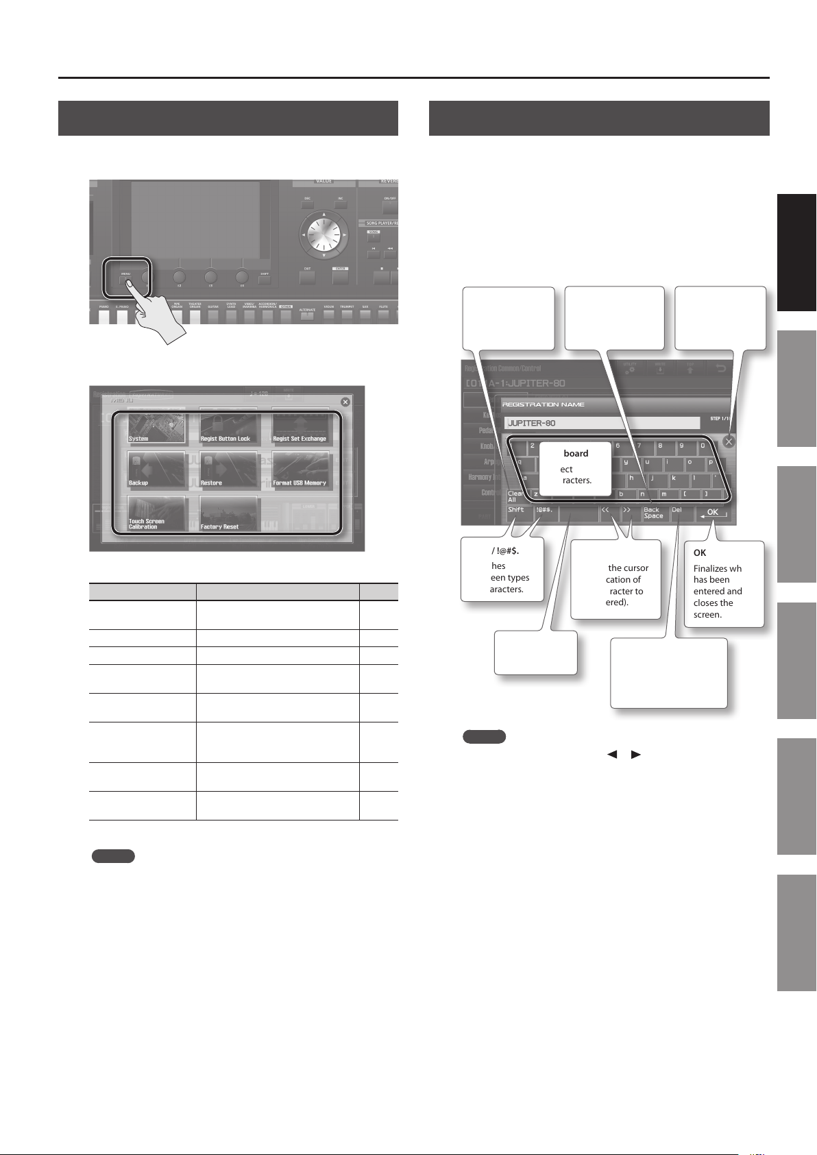
Basic Operation
[MENU] Button Operations
When you press the [MENU] button, the Menu screen will appear in
the display.
Touch an icon in the screen to select the corresponding menu.
Assigning a Name
The JUPITER-80 lets you assign names to the following items.
• Registration
• Live set
• SuperNATURAL Synth Tone
• User arpeggio style
• Song
Regardless of what you’re naming, the procedure is the same.
Clear All
Deletes all
characters that
you’ve entered.
Back Space
Deletes the
character to the left
of the cursor.
Keyboard
Select
characters.
Introduction Playing Sounds Editing Sounds
×
Cancels what has
been entered and
closes the screen.
Menu Explanation Page
System
Regist Button Lock Lock the Registration buttons. p. 81
Regist Set Exchange Exchanges Registration Sets. p. 82
Backup
Restore
Format USB Memory
Touch Screen
Calibration
Factory Reset
Make overall settings for the entire
JUPITER-80.
Backs up the JUPITER-80’s settings to a
USB ash drive.
Restores the JUPITER-80’s settings from
a USB ash drive.
Format the USB ash drive that’s
connected to the USB MEMORY
connector.
Calibrates the touch panel. p. 82
Resets the JUPITER-80 to its factory
settings.
p. 83
p. 79
p. 80
p. 81
p. 87
MEMO
You can also use the value dial or cursor buttons to select an
icon in the menu screen, and press the [ENTER] button to select
it.
Shift / !@#$.
Switches
between types
of characters.
Space
Enters a space.
<< / >>
Moves the cursor
(the location of
the character to
be entered).
Del
Deletes the character to
the right of the cursor
location.
OK
Finalizes what
has been
entered and
closes the
screen.
MEMO
You can also use the cursor [
] [ ] buttons to move the
cursor, and use the value dial or [DEC] [INC] to select the
character that you want to enter.
Other Convenient
Functions
Connecting Other
Equipment
Appendix
29
Page 30
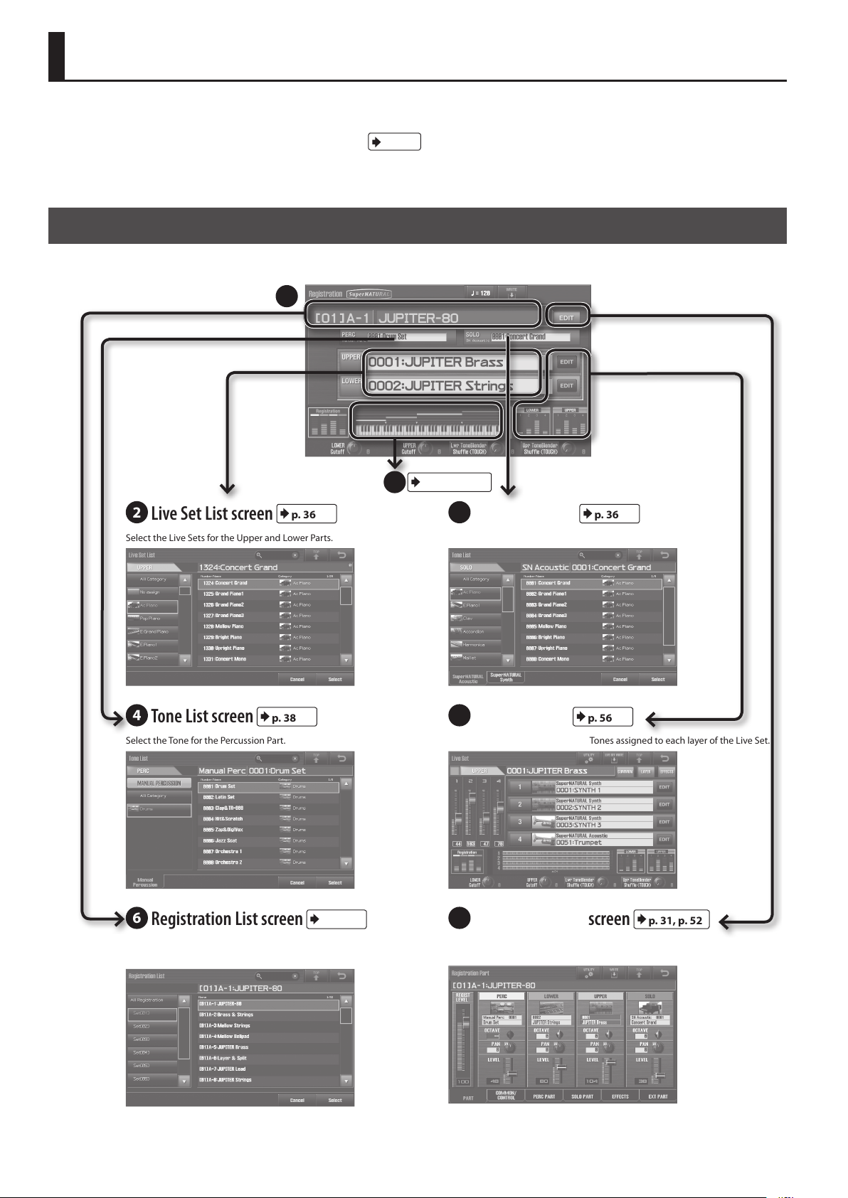
Navigating Between Screens
On the JUPITER-80, you navigate between screens by touching the enclosed areas or buttons shown in the illustrations below. Here we explain how
to navigate between screens.
For details on each screen, refer to the page indicated by the
The explanations in this manual include illustrations that depict what should typically be shown by the display. Note, however, that your unit may
incorporate a newer, enhanced version of the system (e.g., includes newer sounds), so what you actually see in the display may not always match
what appears in the manual.
Registration screen
This is the main screen that appears when you turn on the power. It shows the name of the currently selected Registration, the sound and volume of
each Part, and the split status.
1
p. XX
symbol.
p. 34, p. 39
25
2
Live Set List screen
Select the Live Sets for the Upper and Lower Parts. Select the Tone for the Solo Part.
4
Tone List screen
Select the Tone for the Percussion Part. View the name and volume of the Tones assigned to each layer of the Live Set.
p. 36
p. 38
3
Tone List screen
5
Live Set screen
p. 36
p. 56
30
6
Registration List screen
Select a Registration from a list View the Registration’s volume, and settings such as the volume and pan of
p. 41
7
Registration Part screen
each Part.
p. 31, p. 52
Page 31

Registration Part screen
Here you can view the volume of the Registration, and the volume and pan settings of each Part.
7
Navigating Between Screens
432
p. 36, p. 38
8
Registration PERC Part screen
Edit the settings of the Percussion Part. Edit the settings of the Solo Part.
10
Registration Common/Control screen
Make overall settings for the Registration.
p. 52
p. 52
9
Registration SOLO Part screen
11
Registration Eects Routing screen
Edit the eect settings for the Registration.
p. 52
Introduction Playing Sounds Editing Sounds
p. 52
Other Convenient
Functions
12
Registration External Part screen
Edit Part settings for an external MIDI device.
Connecting Other
Equipment
p. 91
Appendix
31
Page 32

Navigating Between Screens
Live Set screen
View the name and volume of the Tones assigned to each layer of the Live Set.
5
1
p. 30
13
Tone List screen
Select the Tone for each layer. Edit the eect settings for the Live Set.
15
Live Set Tone Modify screen
Edit the sound of each layer. Edit the settings of each layer.
p. 57
p. 56
14
Live Set Eects Routing screen
16
Live Set Layer screen
p. 59
24
p. 34, p. 61
p. 56
21
p. 34
17
Live Set List screen
Select a Live Set. Make overall settings for the Live Set.
32
p. 36
18
24
p. 34, p. 61
Live Set Common screen
24
p. 34, p. 61
p. 56
24
p. 34, p. 61
Page 33

Live Set Eects Routing screen
Edit the eect settings for the Live Set.
14
Navigating Between Screens
24
p. 34, p. 61
Introduction Playing Sounds Editing Sounds
19
Live Set MFX screen
p. 59
Synth Tone Edit (OSC/FILTER/AMP) screen
Edit the oscillator, lter, and amp settings of the SuperNATURAL Synth Tone.
21
20
Live Set Reverb screen
Edit the reverb parameters of the Live Set.
p. 59
Other Convenient
Functions
Connecting Other
Equipment
22
LFO screen
Edit the Tone’s LFO settings. Make detailed settings for the Tone.
p. 66
23
Pro Edit screen
p. 66
Appendix
33
Page 34

Navigating Between Screens
Tone Blender screen
Simultaneously edit multiple parameters of the Live Set.
p. 61
24
Key Range View screen
View the split and key range status.
p. 39
25
Song screen
Press the [SONG] button to access the Song screen.
Here you can operate the USB song player/recorder.
p. 72
Visual Control screen
The Visual Control screen will appear when you press the [VISUAL
CONTROL] button.
Here you can use the JUPITER-80 to control video equipment that
supports Visual Control.
MENU screen
Press the [MENU] button to access the MENU screen.
From here you can access the JUPITER-80’s settings and numerous
functions.
p. 29
p. 95
34
Page 35

Playing Sounds
Introduction Playing Sounds Editing Sounds
Other Convenient
Functions
Connecting Other
Equipment
Appendix
Page 36

Selecting the Sound for Each Part (Selecting Live Sets / Tones)
The JUPITER-80 has four Parts: Solo, Upper, Lower, and Percussion.
You can assign a Tone or Live Set to each Part, and play it.
Solo Part
Upper Part
Lower Part
Percussion Part
You can use the value dial or the [DEC] [INC] buttons to switch the
sound name at the cursor location in the Registration screen (p. 30).
You can also move the cursor to the sound name of each Part and
then touch the sound name again to view a list.
Select sounds.
Tone
Live Set
Live Set
Tone
2. If you press the same Part sound button once again, you’ll
be able to choose sounds from a list.
1
Select a sound category.
2
Select a sound.
3
Conrm your selection.
MEMO
You can use the same procedure to select a Tone for the Solo
Part.
REFERENCE
For details on selecting sounds for the Percussion Part, refer to
“Playing Drum Sounds and Sound Eects (Percussion)” (p. 38).
REFERENCE
For details on operations in this screen, refer to “Basic Touch
Panel Operation” (p. 27).
Using the Part Sound Buttons to Switch Live Sets or the Solo Part’s Tone
You can use the Part sound buttons to switch Live Sets for the
Upper Part and Lower Part, and to switch the Tone of the Solo Part.
As an example, here’s how to switch the Live Set of the Upper Part.
1. Access the Registration screen (p. 30), and press one of the
Part sound buttons for the Upper Part.
Upper
The sound of the Upper Part will change.
For example, if you press the UPPER [PIANO] button, the Upper Part
will switch to a piano sound.
Sound buttons and sound categories
The sound buttons correspond to the following sound categories.
Upper Part
Button Category Explanation
Ac. Piano Acoustic piano
PIANO
E. PIANO
CLAV Clav Clavi
COMBO ORGAN E. Organ Electric organ
PIPE
ORGAN
THEATER
ORGAN
GUITAR
SYNTH
LEAD
VIBES/
MARIMBA
ACCORDION/
HARMONICA
OTHER All Categories All sounds
Pop Piano Piano suitable for pop music
E. Grand Piano Electric grand piano
E. Piano 1
E. Piano 2
Pipe Organ Pipe organ
Pipe Organ Theater organ
Ac. Guitar Acoustic guitar
E. Guitar Electric guitar
Dist. Guitar Distortion guitar
Synth Lead Synth read
Mallet Vibraphone and marimba
Accordion Accordion
Harmonica Harmonica
Electric piano
36
Page 37

Selecting the Sound for Each Part (Selecting Live Sets / Tones)
Lower Part
Button Category Explanation
Ac. Bass Acoustic bass
BASS
PAD
CHOIR Vox/Choir Human voice and choir
STRINGS
SYNTH
STRINGS
BRASS/SAX
SYHTH
BRASS
WOOD
WINDS
OTHER All Categories All sounds
E. Bass Electric bass
Synth Bass Synth bass
Synth Pad/Strings Synth pads and synth strings
Synth Bellpad Synth bellpad
Solo Strings Solo Strings
Ensemble Strings String ensembles
Orchestral Orchestral strings
Synth Pad/Strings Synth pads and synth strings
Solo Brass Brass instruments such as trumpet
Ensemble Brass Brass instrument ensembles
Sax Sax
Synth Brass Synth brass
Wind Woodwinds
Flute Flute
Recorder Recorder
Instantly Switching the Variation Sounds (Alternate Button)
By pressing the [ALTERNATE] button, you can select a dierent
sound of the same type as that of the Part sound button.
The sound that’s selected will be the one that is specied in “LIVE
SET/TONE BUTTONS” (p. 87) (with the factory settings).
MEMO
If the [ALTERNATE] button is turned on, pressing a Part sound
button will display all categories.
For example, you can also assign sounds of other types (such as
bass) to the [PIANO] button.
Turning Each Part On/O and
Adjusting its Volume
When the Registration screen is displayed, you can use the panel’s
PART BALANCE area to turn each of the four Parts on/o and adjust
their volume.
Introduction Playing Sounds Editing Sounds
Solo Part
Button Category Explanation
VIOLIN Solo Strings Solo strings such as violin
TRUMPET Solo Brass Brass instruments such as trumpet
SAX Sax Sax
FLUTE Flute Flute
OBOE Wind Woodwinds such as oboe
BELL Bell Bell
All sounds
OTHER All Categories
MEMO
The sound that is selected when you press a sound button is
determined by the “LIVE SET/TONE BUTTONS” (p. 87).
* The SuperNATURAL Acoustic
Tone 0028: TW Organ cannot be
selected.
Use the sliders to
adjust the volume of
each Part.
The level meter
shows the volume
setting for each Part.
Turn each Part
on/o.
Other Convenient
Functions
Connecting Other
Equipment
Appendix
37
Page 38

Playing Drum Sounds and Sound Eects (Percussion)
The JUPITER-80 provides a “Percussion” function, which lets you play
a variety of drum sounds and sound eects.
Playing Percussion Sounds and Voice Phrases (Manual Percussion)
You can use the 15 leftmost keys of the keyboard to play a variety of
percussion instrument sounds and voice phrases.
This function is called “Manual Percussion.”
Percussion instrument sounds (15 keys)
1. Press the [MANUAL PERCUSSION] button.
Playing Drum Sounds on the Entire Keyboard (Drums/SFX)
You can use the entire keyboard to play various drum and sound
eects (SFX). This function is called “Drums/SFX.”
1. Press the [DRUMS/SFX] button.
The “Drums/SFX” function will turn on (the button will be lit). Play
the keyboard; each key will play a dierent drum sound or sound
eect.
MEMO
• Depending on the drums or sound eects, some keys might not
produce sound.
• If Split (p. 39) is on, you can play drums/SFX in the same region of
keys as the Lower Part.
2. To turn this o, press the [DRUMS/SFX] button once again.
The “Drums/SFX” function will turn o (the button will be unlit.)
The Manual Percussion function will turn on (the button will be lit).
Play the 15 leftmost keys of the keyboard, and you’ll hear a dierent
percussion instrument sound or voice phrase for each key.
Percussion instrument sounds
(15 keys)
NOTE
• The [MANUAL PERCUSSION] button and [DRUMS/SFX] button
can’t be used simultaneously.
• If Manual Percussion is turned on, the 15 leftmost keys of the
keyboard are used only for the Percussion Part.
Switching the Sounds Played by Manual Percussion or Drums/SFX
There are 8 types of Manual Percussion, and 16 types of Drums/SFX
sound sets. You can switch between these as desired.
1. In the Registration screen (p. 30), touch a sound name to
access a list.
Percussion tone name
The Tone List screen will appear.
2. Select the desired sound.
1
Select a sound category.
2
Select a sound.
2. To turn this o, press the [MANUAL PERCUSSION] button
once again.
The Manual Percussion function will turn o (the button will be
unlit).
38
3
Conrm your selection.
* The available sounds will dier for Manual Percussion and
drums/SFX.
Page 39

Split Performance
A “split” is a setup in which the keyboard is divided into zones, each
playing a dierent Part.
Lower Part
Splits can be either “splits,” which divide the keyboard into an Upper
Part and Lower Part, or “Solo Splits,” which divide the keyboard
into a Solo Part and Upper Part. The point at which the keyboard is
divided is called either the “Lower Split Point” or “Solo Split Point.”
If Split is turned on, keys to the right of the Lower Split Point will
play the sound of the Upper Part, and keys to the left will play the
sound of the Lower Part.
The Lower Split Point key itself (B3) is the highest key of the Lower
Part (it is included in the Lower Part).
Upper Part
Lower Split Point (B3)
Solo Part
Solo Split Point (C6)
Turning Split On
1. Press the [SPLIT] button or [SOLO SPLIT] button.
Introduction Playing Sounds Editing Sounds
Split or Solo Split will turn on (the button will light).
The screen will indicate the split status.
Solo Split PointLower Split Point
If Solo Split is turned on, keys to the right of the Solo Split Point will
play the sound of the Solo Part, and keys to the left will play the
sound of the Upper Part.
The Solo Split Point key itself (C6) is the lowest key of the Solo Part
(it is included in the Solo Part).
MEMO
• You can change the Lower Split Point and the Solo Split Point
(p. 40).
• The split settings are saved in the Registration.
• For more about split for the Percussion Part, refer to “How Split
and Parts are Related” (p. 40).
2. To turn it o, press the [SPLIT] button or [SOLO SPLIT]
button once again.
Split or Solo Split will turn o (the button will go out).
Checking Splits and Key Ranges
Touch the keyboard graphic in the Registration screen to check the split and key range settings (p. 34).
Turns split on/o. Turns Solo Split on/o.
Turn the Part
on/o.
Species the
key range.
Lower Part
Upper Part
Solo Part
Other Convenient
Functions
Connecting Other
Equipment
Appendix
Turns layer on/o.
Species the
type of tone.
Species the
tone.
Indicates the key range (sound is
produced in the specied region).
39
Page 40

Split Performance
How Split and Parts are Related
The following table shows how the split status determines the Parts that are assigned to the keyboard.
[DRUMS/SFX]
On
On On
On On
On On On
[MANUAL
PERCUSSION]
On
[SPLIT] [SOLO SPLIT ]
Solo
Upper
Lower
Percussion
On On
On On
On On On
Changing the Split Point
You can change the point (Lower Split Point or Solo Split Point) at which the keyboard is divided when Split or Solo Split are on.
The Lower Split Point is the top key of the Lower Part; you can specify it in the range of E1–F#7.
The Solo Split Point is the bottom key of the Solo Part; you can specify it in the range of F1–G7.
1. Hold down the [SPLIT] button or [SOLO SPLIT] button, and press the key that you want to specify as the split point.
Hold down the [SPLIT] button and press a key to specify the Lower Split Point. Hold down the [SOLO SPLIT] button and press a key to specify the Solo
Split Point.
40
Page 41

Switching Registrations
A Registration is used to store the sounds selected for each Part, as
well as various performance-related settings (system parameters
are excepted).
By switching Registrations, you can instantly change the song’s
sounds while you perform, or change numerous settings with a
single operation.
Here’s how to switch Registrations and verify that the settings have
been changed.
1. Press a Registration button ([1]–[8]) to select a
Registration.
Switching Banks
Each bank contains 8 Registrations. There are 4 banks, A–D,
meaning that 8 Registrations x 4 banks = 32 Registrations are
available.
Here’s how to select other Registrations by switching banks.
Introduction Playing Sounds Editing Sounds
The Registration will change.
MEMO
• In the Registration screen, you can also switch Registrations by
moving the cursor to the Registration name and using the value
dial or the [DEC] [INC] buttons.
• You can use the “Registration Lock” function (p. 81) to lock the
Registration buttons so that the settings will not be changed
inadvertently.
Bank
(A–D)
You can select other Registrations by switching banks.
Registration (1–8)
1. Press a bank button ([A]–[D]) to select a bank.
The selected bank button ([A]–[D]) and the Registration buttons
([1]–[8]) will blink.
MEMO
If you decide not to switch banks, press the [EXIT] button or the
bank button that’s blinking.
2. Press a Registration button ([1]–[8]) to select a
Registration.
The bank and Registration will be changed.
Other Convenient
Functions
41
Connecting Other
Equipment
Appendix
Page 42

Switching Registrations
Switching Registration Sets
A Registration Set contains 4 banks (A–D). You can create 8
Registration Sets, meaning that 8 Registrations x 4 banks x 8 sets =
256 Registrations are available.
Here’s how to switch the Registration Set so that you can select
other banks.
Set 8
Set 1
Bank
(A–D)
You can use the [NEXT] button and [PREV] button to switch
Registration Sets.
1. Set the system parameter “Registration Next/Prev Button”
(p. 86) to “REGISTRATION SET.”
MEMO
With the factory settings, Registration Next/Prev Button is set to
“REGISTRATION SET.”
Registration (1–8)
Switching Registrations Consecutively
Here’s how to switch Registrations consecutively.
1. Set the system parameter“Registration Next/Prev Button”
(p. 86) to “REGISTRATION.”
MEMO
If you decide not to switch banks, press the [EXIT] button or the
bank button that’s blinking.
2. Press the [NEXT] button or [PREV] button.
Pressing the [NEXT] button steps you through the Registrations in
the following order.
Set 1
2. Press the [NEXT] button or [PREV] button.
Pressing the [NEXT] button switches to the next Registration Set;
pressing the [PREV] button switches to the previous Registration
Set.
The display indicates the Registration Set that’s selected.
Registration Set
MEMO
• If “Registration Next/Prev Button” (p. 86) is set to “REGISTRATION,”
you can also switch Registration Sets by holding down the
[SHIFT] button and pressing the [PREV] button or [NEXT] button.
• You can use the “Registration Exchange” function (p. 82) to swap
entire sets of Registrations.
Set 2
Set 8
MEMO
Pressing the [PREV] button steps you through the Registrations
in the opposite order.
42
Page 43

Using the Arpeggiator
The JUPITER-80 has an arpeggiator that automatically plays
arpeggios. When you press notes on the keyboard, those notes will
be automatically played as an arpeggio.
Arpeggios can be played in the Lower Part and Upper Part.
MEMO
Arpeggiator settings are saved in the Registration.
Turning the Arpeggiator On
1. Press the ARPEGGIO [LOWER ON/OFF] button or
ARPEGGIO [UPPER ON/OFF] button.
The arpeggiator will turn on (the button will light).
2. Press a chord on the keyboard.
The Part whose arpeggiator you turned on will sound an arpeggio
consisting of the notes of the chord you play.
3. To turn o the arpeggiator, press the ARPEGGIO [LOWER
ON/OFF] button or the ARPEGGIO [UPPER ON/OFF] button
once again.
The arpeggiator will turn o (the button will go out).
Holding the Arpeggio (HOLD)
The Hold function allows you to have the arpeggio continue even
after you release your ngers from the keyboard.
1. Press the [HOLD] button.
Introduction Playing Sounds Editing Sounds
Hold will turn on (the button will light).
2. Play a chord on the keyboard.
According to the notes of the chord you press, an arpeggio will
begin playing on the Part for which you turned the arpeggiator on.
If you play a dierent chord or other keys while Hold is on, the
arpeggio will change accordingly.
3. To turn Hold o, press the [HOLD] button once again.
Hold will turn o (the button will go out).
Using a pedal switch
By playing a chord while holding down a pedal
switch (p. 20), you can make the arpeggio continue
playing even after you release the keyboard.
1. Connect a pedal switch (such as one from
the DP series; sold separately) to the HOLD
jack.
Setting the Arpeggiator Tempo
Here’s how to set the tempo of the arpeggiator/rhythm function.
1. Press the [TEMPO] button.
The Tempo screen will appear.
2. Set the tempo.
MEMO
You can set the tempo by pressing the [TEMPO] button or
touching <Tap Tempo> at the desired timing (Tap Tempo). Press
(or touch) three times or more at quarter-note intervals of the
desired tempo.
2. Press the ARPEGGIO [LOWER ON/OFF] button or the
ARPEGGIO [UPPER ON/OFF] button.
3. Hold down the pedal switch, and play a chord.
If you play other chords or keys while the arpeggio is being held,
the arpeggio will change accordingly.
Other Convenient
Functions
Connecting Other
Equipment
Appendix
3. Touch <Close>.
43
Page 44

Using the Arpeggiator
Editing the Arpeggiator Settings
Here’s how to make detailed arpeggiator settings for the style,
timing, and accent.
1. Hold down the [SHIFT] button and press the ARPEGGIO
[LOWER ON/OFF] button or ARPEGGIO [UPPER ON/OFF]
button.
The Registration Common/Control screen (p. 31) will appear.
2. Edit the settings.
3. When you’ve nished editing, press the [EXIT] button.
Arpeggio Parameters
Parameter Value Explanation
Species the basic style of the arpeggio.
Style
Hold OFF, ON
Variation 1–
Motif
Velocity REAL, 1–127
P001–P128,
U001–U128
Choose one of the following to specify the order in which the
notes of the chord you play will be sounded.
UP
DOWN
UP&DOWN
RANDOM
NOTE ORDER
GLISSANDO
CHORD
AUTO1
AUTO2
PHRASE
You can create your own original arpeggio
style by importing an SMF into an arpeggio
style. For details, refer to “Creating an Arpeggio Style from a MIDI File (Import)” (p. 45)..
Turns the arpeggio hold function on/o.
Each arpeggio style provides several
variations (patterns). Here you can select the
variation number. The number of variations
will depend on the arpeggio style.
The notes will be sounded from the lowest
to the highest note you play.
The notes will be sounded from the highest
to the lowest note you play.
The notes will be sounded from the lowest
to the highest note, and then back down to
the lowest note.
The notes you play will be sounded in
random order.
The notes you play will be sounded in the
order you played them. You can create a
melody line by playing the notes in the
appropriate order. The order of up to 128
notes can be remembered.
A chromatic glissando will be sounded
upward and then downward repeatedly
between the lowest and highest notes
you played. Play two notes; the lowest and
highest desired notes.
All of the notes you play will sound
simultaneously.
The timing at which each note will sound
is assigned automatically, starting at the
lowest note you play.
The timing at which each note will sound
is assigned automatically, starting at the
highest note you play.
Play only one key; a phrase based on the
pitch of that key will be sounded. If you play
more than one key, the last key you play will
take priority.
Species the loudness at which the notes
you play will be sounded. If you want the
notes to be sounded at the velocity with
which you actually struck the key, choose
“REAL.” If you want the notes to be sounded
at a xed velocity regardless of how strongly
you struck the key, specify that value
(1–127).
Oct Range -3–+3
Accent 0–100%
Shue Rate 0–100%
Shue
Resolution
,
Species the range in octaves in which the
arpeggio will be sounded. Choose “0” if you
want only the notes you play to be sounded.
Choose “+1” if you want the notes of the
chord you played as well as the same notes
one octave higher to be sounded. Choose
“-1” if you want the notes of the chord you
played as well as the notes one octave lower
to be sounded.
Modies the groove of the performance by
adjusting the strength of the accents and
the duration of the notes. The “100%” setting
produces the strongest sense of groove.
Produces a shue rhythm by adjusting the
timing of the notes.
With the “50%” setting, notes will be
sounded at equal intervals. As this value is
increased, the result will be more like dotted
notes.
Shue Rate= 50%
50 5050 50
Shue Rate= 90%
90 10 90 10
Species the timing (as a note value) at
which the notes will be heard.
44
Page 45

Creating an Arpeggio Style from a MIDI File (Import)
You can create your own original arpeggio style by importing an
SMF (Standard MIDI File).
Using the Arpeggiator
4. Select the SMF that you want to import, and then touch
<IMPORT>.
1
Select the SMF.
MEMO
• Before you import the SMF, use your computer to copy the SMF
to the root folder (top level) of your USB ash drive, or create a
folder on your USB ash drive and copy the SMF into that folder.
• Use only single-byte alphanumeric characters in the le name
and folder name.
• A maximum of 200 les can be recognized within a folder.
1. Hold down the [SHIFT] button and press the ARPEGGIO
[LOWER ON/OFF] or ARPEGGIO [UPPER ON/OFF] button.
The Registration Common/Control screen will appear.
2. Select the import-destination user style (U001–U128).
3. Touch <SMF IMPORT>.
2
Conrm your selection.
5. Assign a name to the arpeggio style.
For details on how to assign a name, refer to ““Assigning a Name”
(p. 29).
6. Touch <OK>.
The screen will ask “Are you sure?”
7. Touch <OK>.
The SMF will be imported into the style number you specied.
* Please note the following points when importing an arpeggio.
• Only SMF Format 0 data is supported. If the format is incorrect,
the screen will indicate “Cannot Import SMF Format 1!” or
“Incorrect File!”
• Only the following data will be imported into the arpeggio: note
messages, control change messages, channel pressure, and
pitch bend.
• A maximum of 500 note events can be imported, with on/o
counted as a single event.
In addition to note events, a total of up to 500 events of control
change messages, channel pressure, and pitch bend can be
imported. If you try to import more than the allowable number
of events, the message “Too Much Data!” will appear.
Introduction Playing Sounds Editing Sounds
Other Convenient
Functions
MEMO
If you don’t select U001–U128 as the Style number, <SMF
IMPORT> will not be available to touch.
Connecting Other
Equipment
Appendix
45
Page 46

Performing With Added Harmony
The Harmony Intelligence function adds appropriate harmony to
the highest notes of the Upper Part, based on the chords you play
in the Lower Part.
When you turn Harmony Intelligence on, Split (p. 39) will also turn on;
the right keyboard zone will play the sound of the Upper Part, and
the left keyboard zone will play the sound of the Lower Part.
MEMO
Harmony Intelligence settings are saved in the Registration.
1. Press the [HARMONY INTELLIGENCE] button.
Harmony Intelligence will turn on (the button will light).
MEMO
When you turn on Harmony Intelligence, the split (p. 39) will also
turn on automatically.
2. Press a chord in the Lower Part, and play the keyboard in
the Upper Part.
Harmony based on the chord of the Lower Part will be added to the
Upper Part.
MEMO
The harmony is added to the highest note played in the Upper
Part.
3. To turn o the function, press the [HARMONY
INTELLIGENCE] button once again.
Harmony Intelligence will turn o (the button will go out).
MEMO
Turning o Harmony Intelligence will not automatically turn o
the split function (p. 39).
Changing the Harmony Intelligence Type
You can choose from 17 types of Harmony Intelligence.
The Harmony Intelligence type will aect the number of harmony
notes and how they are sounded (the number of voices played).
2. Choose the desired Harmony Type.
Harmony Type Explanation
ORGAN
BIG BAND
STRINGS
BLOCK
HYMN
TRADITIONAL
DUET
COMBO
COUNTRY
BROADWAY
GOSPEL
OCTAVE1
OCTAVE2
1NOTE
2NOTES
3NOTES
4NOTES
MEMO
For optimal harmony, select appropriate sounds for the Upper
Part and Lower Part as indicated in the explanation for each
harmony type.
Harmony appropriate for organ sounds will be
produced.
Harmony typical of big band jazz will be produced.
This is appropriate for brass sounds.
Harmony typical of a string ensemble will be
produced. This is appropriate for string sounds.
Block chord harmony will be produced.
This is appropriate for piano or mallet sounds.
Harmony appropriate for hymns will be produced.
This is appropriate for choir sounds.
Two notes of harmony will be added to the notes
you play.
Simple duet harmony will be produced. This is
appropriate for brass sounds.
Combination harmony will be produced.
This is appropriate for brass or wind sounds.
Open chord harmony will be produced.
This is appropriate for guitar sounds.
Flamboyant show-type harmony will be produced.
This is appropriate for organ sounds.
Gospel harmony will be produced. This is appropriate
for organ or choir sounds.
The note you play will be layered with a note one
octave lower.
The note you play will be layered with a note two
octaves lower.
One note of harmony will be added to the note you
play.
Two notes of harmony will be added to the note you
play.
Three notes of harmony will be added to the note
you play.
Four notes of harmony will be added to the note
you play.
3. Press the [EXIT] button.
When Harmony Intelligence is on, the name of the chord you
play in the Lower Part is shown in the Registration screen.
1. Hold down the [SHIFT] button and press the [HARMONY
INTELLIGENCE] button.
The Registration Common/Control screen (p. 31) for Harmony
Intelligence settings will appear.
46
Chord name played in
the Lower Part
Page 47

Controlling the Performance
Moving Your Hand to Modify the Pitch or Volume (D Beam Controller)
You use the D Beam controller simply by moving your hand above
it. By assigning dierent functions to it, you can control the sound
in various ways.
MEMO
D Beam controller settings are saved in the Registration.
1. Press the D BEAM [PITCH], [VOLUME], or [ASSIGNABLE]
button to turn the D Beam controller on.
Button Explanation
[PITCH] button
[VOLUME] button
[ASSIGNABLE] button
MEMO
You can assign a performance-related function to the
[ASSIGNABLE] button. The function assigned to the
[ASSIGNABLE] button is specied by the Registration Common/
Control parameter D Beam (p. 31).
The pitch will change as you move your hand
above the D Beam controller.
The volume will change, allowing you to add
expression to your performance.
The function assigned to the D Beam
controller will be controlled.
Changing the Pitch/Applying Vibrato (Pitch Bend/Modulation Lever)
While playing the keyboard, move the lever toward the left to lower
the pitch, or toward the right to raise the pitch. This is called “pitch
bend.”
Moving the lever away from yourself will apply vibrato.
This is called “modulation.”
Moving the lever away from yourself while also moving it to left or
right will apply both eects simultaneously.
MEMO
For some sounds, the modulation lever will produce a dynamics
eect.
Using the Buttons and Knobs to Modify the Sound ([S1] [S2] buttons / [E1]–[E4] knobs)
Performance-related functions are assigned to the [S1] [S2] buttons
and [E1]–[E4] knobs. While you perform, you can operate the [S1]
[S2] buttons or [E1]–[E4] knobs to modify the sound in real time.
Turning the [S1] [S2] buttons on/o will turn on/o or switch the
assigned function.
Introduction Playing Sounds Editing Sounds
Other Convenient
Functions
2. While playing the keyboard to produce sound, position
your hand above the D Beam controller and slowly move
it up and down.
3. To turn o the D Beam controller, once again press the
button you pressed in step 1 (the button will go out).
Eective range of the D Beam controller
This illustration shows the eective range of the
D Beam controller. No eect will be obtained
if you position your hand outside the eective
range.
NOTE
The eective range of the D Beam controller
will change depending on the lighting
conditions. If the D Beam controller does not
work as you expect, readjust the sensitivity.
For details on readjust the sensitivity, refer to “D Beam Sens” (p.
84).
MEMO
You can assign performance-related functions to the [S1] [S2]
buttons. The [S1] [S2] button assignments are specied by the
Registration Common/Control parameters S1-S2 (p. 31).
If the [E1]–[E4] knobs are shown in the Lower Part of the display,
operating these knobs will control the functions assigned to them.
Connecting Other
Equipment
Appendix
47
Page 48

Controlling the Performance
MEMO
You can assign performance-related functions to the [E1]–[E4]
knobs. The [E1]–[E4] knob assignments are specied by the
Registration Common/Control screen (p. 52).
Using Pedals
The JUPITER-80 allows you to connect hold pedals (such as one
from the DP series; available separately) and expression pedals (EV5; available separately).
If a hold pedal (such as one from the DP series; available separately)
is connected to the rear panel PEDAL HOLD jack, notes will be
sustained (held) while you hold down the pedal even after you take
your hands o the keyboard.
If an expression pedal or pedal switch (EV-5, DP series unit; available
separately) is connected to the rear panel CTRL 1 or CTRL 2 jack,
you can use the pedal to vary the volume or control a variety of
functions.
Sustaining the Notes (Hold Pedal)
While playing the keyboard, step on the pedal switch.
You can hold (sustain) the notes by stepping on the pedal switch.
Adding Expression to Your Performance (Control Pedal)
While playing the keyboard, raise or lower the expression pedal.
You can make your performance more expressive by varying the
volume.
* You must use the specied expression pedal (EV-5; available
separately). Connecting a product made by another
manufacturer may cause the JUPITER-80 to malfunction.
MEMO
Performance-related functions can be assigned to the pedals
connected to the CTRL 1 and CTRL 2 jacks. The CTRL 1 and
CTRL 2 assignments are specied by the”Control Pedal” (p. 83)
parameters Control Pedal 1 Assign and Control Pedal 2 Assign.
48
Page 49

Controlling the Rotary Eect and Reverb
The rotary eect adds modulation similar to what is produced by
rotary speakers to the sound. Reverb applies the reverberation
that accompanies a sound played in a hall or other acoustic
environment.
You can control these eects by using panel buttons.
Controlling the Rotary Eect
The ROTARY SOUND [ON/OFF] button and [SLOW/FAST] button
allow you to control the eect if a rotary eect is assigned to MFX.
1. First, assign 21: Rotary or 22: VK-Rotary to the MFX of the
Live Set (p. 58).
2. Press the ROTARY SOUND [ON/OFF] button.
The rotary eect will turn on (the button will light).
Controlling Reverb
The REVERB [ON/OFF] button simultaneously turns on/o the
output of the Live Set’s reverb and of the reverb shared by the Solo
and Percussion Parts.
If you want reverb to always be o, turn o the REVERB [ON/OFF]
button.
The illustration below shows how the REVERB [ON/OFF] button
works.
Registration
Solo Part/Percussion Part
Introduction Playing Sounds Editing Sounds
3. Press the ROTARY SOUND [SLOW/FAST] button.
The speed of the rotary eect will change.
The rotary eect can be switched between two settings: “SLOW”
and “FAST.”
ROTARY SOUND
[SLOW/FAST]
button
Unlit (SLOW)
Lit (FAST)
When you switch the rotary eect from “SLOW” to “FAST,” the
modulation speed will increase; when you switch from “FAST” to
“SLOW,” the modulation speed will decrease.
Explanation
The eect produced when the rotary speaker is
turning slowly.
The eect produced when the rotary speaker is
turning rapidly.
Upper Part
Live set
Lower Part
Live set
MEMO
The state of the REVERB [ON/OFF] button is not saved. It will
automatically turn on when you turn on the power.
Reverb
Reverb
Reverb
REVERB
[ON/OFF]
Other Convenient
Functions
Connecting Other
Equipment
49
Appendix
Page 50

Changing the Keyboard Settings
Changing the Pitch by Octaves
By pressing the OCTAVE [DOWN] button or OCTAVE [UP] button you
can shift the keyboard’s pitch range in steps of an octave.
When using your right hand to play low sounds such as the bass
Part, it will be easier to play if you lower the pitch range by one or
two octaves.
1. Press the OCTAVE [DOWN] button or OCTAVE [UP] button.
A message will appear when you press the button.
Transposing
Transpose is a function that shifts the keyboard’s pitch range in
steps of a semitone.
By using this setting, a transposing instrument such as trumpet or
clarinet can be played at the pitches shown in the printed score.
1. Hold down the [TRANSPOSE] button and press the
OCTAVE [DOWN] button or OCTAVE [UP] button.
A message will appear when you press the button. The Registration
screen will show the amount of transposition.
Amount of transposition
• Pressing the OCTAVE [DOWN] button raises the pitch by one
octave; pressing the OCTAVE [UP] button lowers the pitch by
one octave.
• The pitch can be changed in a range of three octaves down (-3)
to three octaves up (+3).
• If the value is anything other than “0,” the OCTAVE [DOWN]
button or OCTAVE [UP] button will light.
• If you press the OCTAVE [DOWN] button and OCTAVE [UP]
button simultaneously, the value will be reset to “0.”
• The octave shift setting is saved in the Registration.
• If you want to change the octave setting of each Part, edit the
Octave setting in the “Registration Part screen” (p. 31), and save
the Registration.
• If you want to change the octave setting of each layer in the
Live Set, edit the Octave setting in <Pitch> of the Live Set Layer
screen (p. 32), and save the Live Set.
• The octave shift function does not aect the Manual Percussion.
• The split point and solo split point will not change.
• Specify the amount of transposition in semitone steps (G–F#:
-5 – +6 semitones).
• If the value is anything other than “0,” the [TRANSPOSE] button
will light.
• You can use the [TRANSPOSE] button to turn Transpose on/o
(when the Transpose setting is other than 0).
• If you hold down the [TRANSPOSE] button and press
the OCTAVE [DOWN] button and OCTAVE [UP] button
simultaneously, the value will be reset to “0.”
• The transpose setting is saved in the Registration.
• The Transpose function does not apply to Drums/SFX or Manual
Percussion.
• The split point and solo split point will not change.
50
Page 51

Editing Sounds
Introduction Playing Sounds Editing Sounds
Other Convenient
Functions
Connecting Other
Equipment
Appendix
Page 52

Editing a Registration
A Registration stores the sounds selected for each Part, as well as
various performance-related settings.
Basic Operation for Registration
The Registration screen (p. 30) shows basic information about the
currently selected Registration.
Percussion tone name
Upper Live Set name
The Registration saves the following parameters.
Tab Explanation
Part-related settings
• Registration Level
PART
COMMON/
CONTROL
PERC PART,
SOLO PART
EFFECTS Eects for the Percussion Part and Solo Part
EXT PART Settings for messages sent to external MIDI devices
• The Live Sets assigned to the Upper Part and Lower Part
• The Tones assigned to the Solo Part and Percussion Part
• Each Part’s octave, pan, volume, etc.
Settings common to the entire Registration
• Registration name
• Registration Level
• Tempo
• Split
• D Beam controller, [S1]/[S2] button, and [E1]–[E4] knob
assignments
• Arpeggiator
• Harmony Intelligence
• Control and other data sent to each Part
• Octave Shift, Transpose, etc.
Settings for the Percussion Part or Solo Part
• Tone, pan, volume, and reverb send level
• Keyboard range
• Pitch
• Vibrato
• Oset values for lter and envelope
• Velocity
• Mono/poly switch
• Legato
• Voice reserve (guaranteed polyphony)
• Control data received by each Part, etc.
Registration name
Lower Live Set name
Solo tone name
Access the Live
Set screen
Editing
1. In the Registration screen (p. 30), touch Registration’s
<EDIT>.
The Registration Part screen will appear.
2. Touch a tab to select the Registration parameters that you
want to edit.
Tabs
MEMO
If a Registration has been edited, a check mark (red) will appear
at the right of the Registration name.
Let’s try editing these parameters.
52
Page 53

Saving a Registration
Editing a Registration
3. Press the blinking Registration button.
A message will ask “Are you sure?”
Edits you make to a Registration are temporary; they will be lost
when you turn o the power or select another Registration. If you
want to keep an edited Registration, you must save it.
NOTE
When you execute the Write operation, the existing data at the
write destination will be overwritten.
REFERENCE
For details on how a Registration is structured, refer to “How
Registrations are Organized” (p. 15).
1. In the Registration screen (p. 30), press the [WRITE] button.
The Registration Write screen will appear. The [WRITE] button will
light, and the Registration buttons will blink.
MEMO
You can also perform a save by touching Registration screen’s
<WRITE>.
MEMO
You can also save by touching <WRITE> in the Registration Write
screen.
4. To write the data, touch <OK>.
The message “Completed!” will appear.
The Registration has been saved.
NOTE
Never turn o the power while data is being saved.
Cancelling the Save of a Registration
You can cancel the save operation by doing one of the following.
• Press the [EXIT] button
• Press the [WRITE] button
• Touch [x] in the Registration Write screen
Introduction Playing Sounds Editing Sounds
2. Move the cursor to Write Destination, and use the
value dial or the [DEC] [INC] buttons to select the write
destination.
Registration number
Naming a Registration
If you want to rename the Registration, touch <RENAME> of
step 2.
The REGISTRATION NAME screen will appear.
Other Convenient
Functions
Connecting Other
Equipment
For details on assigning a name, refer to “Assigning a Name”
(p. 29).
Appendix
MEMO
You can also use the bank buttons ([A]–[D]) and Registration
buttons ([1]–[8]) to directly specify the write destination.
53
Page 54

Editing a Registration
If the following display appears when you save
If Live Set parameters or SuperNATURAL Synth Tone parameters
have been edited, the corresponding Live Set or SuperNATURAL
Synth Tone will be highlighted when you save the Registration.
The Synth Tone has
been edited.
You have the option of saving the edited Live Sets and
SuperNATURAL Synth Tones at the same time that you save the
Registration.
If you want to do this, proceed as follows.
The Live Set has been
edited.
2. If you want to specify the Live Set number or
SuperNATURAL Synth Tone number for saving, touch
<SELECT DEST>.
Live Set Select Destination screen will appear.
3. Select the write destination.
1 2
Select the write destination for the Live Set.
Select the write destination for the SuperNATURAL
Synth Tone.
1. Select the Write check box for the Live Sets and
SuperNATURAL Synth Tones that you want to save.
MEMO
If you save without selecting these check boxes, only the
Registration will be saved. The Live Sets or SuperNATURAL Synth
Tones you’ve edited will remain in their edited state without
being saved.
If you want to specify a Live Set number or SuperNATURAL Synth
Tone number at which to save the data, proceed to step 2. If you
want to save the data by overwriting the current Live Set number
and SuperNATURAL Synth Tone number, proceed to step 4.
3
Conrm selections and
return to the previous screen.
4. Touch <WRITE>.
MEMO
• If you specify the same write destination for the Live Sets of the
Upper Part and Lower Part, the message “Cannot Write!” will
appear. Select dierent write destinations in step 3.
• If you specify the same write destination for the SuperNATURAL
Synth Tones of layers 1–4, the message “Cannot Write!” will
appear. Select dierent write destinations in step 3.
• If the same Live Set is assigned to the Upper Part and the Lower
Part, and you edit only one Part and then execute this operation,
the edited Live Set will be assigned to the other Part as well.
• If the same SuperNATURAL Synth Tone is assigned to layers 1–4,
and you edit only the SuperNATURAL Synth Tone of a specic
layer and then execute this operation, the edited SuperNATURAL
Synth Tone will also be assigned to the other layers.
54
Page 55

Initializing a Registration
Here’s how to initialize the currently selected Registration.
MEMO
• Initializing the Registration will aect the data in the temporary
area (p. 16).
When you initialize the Registration, the Live Sets and tones in
the temporary area will also be initialized.
• If you want to return the parameters of all sounds to their
factory-set state, use Factory Reset (p. 87).
1. In the Registration Part screen (p. 31), touch <UTILITY>.
Editing a Registration
Introduction Playing Sounds Editing Sounds
Registration Utility Menu screen will appear.
2. Touch <Registration Initialize>, and then touch <Select>.
A message will ask “Are you sure?”
3. Touch <OK>.
Other Convenient
Functions
Connecting Other
Equipment
55
Appendix
Page 56

Editing a Live Set
You can edit a Live Set by switching the Tones in the Live Set, and
by adjusting oset values relative to the value of each tone.
The Live Set screen (p. 32) shows basic information about the
currently selected Live Set.
View the Live Set Eects
Routing screen.
Level of each
layer.
View the Live
Registration
screen.
The following parameters are stored in a Live Set.
View the Live Set
Common screen.
Tone name
View the Live Set
Eects screen.
Switch between the Upper
Part and Lower Part
Tips for editing a Live Set
Choose which Parts will be heard
A Registration consists of up to four Parts. Editing will be
easier if you’re listening only to the Parts that are selected for
the Live Set you want to edit (p. 37).
MEMO
When you edit the parameters of a Live Set, you are specifying
a relative increase or decrease applied to the value of the Tone;
the actual tone itself is not aected.
This means that even if the same tone is used by another Live
Set, you’ll be able to edit without aecting the other Live Set.
Basic Editing Operations for Live Sets
To edit a Live Set, you’ll start from the Live Set screen.
1. In the Live Set screen (p. 32), touch the button
(<COMMON>, <LAYER>, <EFFECTS>) of the parameter
that you want to edit.
Tab Explanation
Settings common to the entire Live Set
• Live set name, Live Set category
COMMON
LAYER
EFFECTS
MODIFY
• Volume
• Filter
• Phase lock, etc.
Settings for each layer
• Layer on/o
• Volume
• Pan
• Layer audio output destination and send level
• Keyboard range, etc.
MFX settings
• Layer audio output destination and send level
• Send level to MFX
• MFX on/o
• MFX type selection
• MFX volume
• MFX settings, reverb settings
• Send levels from the Tone to reverb, and from MFX to
reverb, etc.
Oset settings for each layer
For a SuperNATURAL
Synth Tone
• Pitch
• Filter
• Amp
• LFO
• Modulation
• Portamento, etc.
For a SuperNATURAL
Acoustic Tone
• Noise level
• Variation, etc.
2. Touch a tab to select the Live Set parameters that you
want to edit.
Tabs
In this example, the Upper Part’s Live Set is edited.
56
Page 57

MEMO
If a Live Set has been edited, a check mark (red) will appear at
the right of the Live Set name.
Editing a Live Set
Changing a Live Set’s Tones
Here’s how to change the Tones in a Live Set.
1. In the Live Set screen (p. 32), touch a tone name to view a
list.
Adjusting the Tones
By touching <EDIT> of each layer in the Live Set screen (p. 32),
you can adjust the Tones assigned to each layer (the Live Set
Modify screen will appear).
For details, refer to “Editing the Tones Assigned to a Layer”
(p. 60).
MEMO
You can also switch tones by moving the cursor to the tone
name in the Live Set screen, and using the value dial or the
[DEC] [INC] buttons to select a Tone.
The Tone List screen will appear. In this example, the Tone for layer 1
of the Live Sets assigned to the Upper Part is changed.
2. Touch the new tone, and then touch <Select>.
The left column lists the tone categories, and the right column lists
the Tones in the selected category.
2
Select a category.
3
Select a Tone.
Introduction Playing Sounds Editing Sounds
Other Convenient
Functions
1
Select the type of tone.
The Tone will change.
MEMO
The SuperNATURAL Acoustic Tone 0028: TW Organ can be
assigned only to layer 1.
4
Conrm your
selection.
Connecting Other
Equipment
Appendix
57
Page 58

Editing a Live Set
Layer On/O and Volume Adjustment
To turn a layer on/o, touch its layer number in the Live Set screen
(p. 32).
Layer button Status
O
On
MEMO
In the panel’s PART BALANCE area you can turn the four layers
on/o and adjust their volume.
Switching the MFX (Multi-eects)
Each Live Set contains four MFX (multi-eects) processors.
To switch the MFX, access the “Live Set Eects Routing” screen.
1. In the Live Set Eects Routing screen (p. 33), touch the MFX
eect type to access a list.
Touch an eect type.
The MFX Type screen will appear. In this example, the eect type for
MFX1 of the Live Set selected for the Upper Part is changed.
MEMO
If you move the cursor to the eect type, you’ll also be able to
use the value dial or the [DEC] [INC] buttons to switch the eect
type.
Use the sliders to adjust
the volume of each
layer.
The level meters show
the volume setting of
each layer.
Turn each layer on/o.
MEMO
By holding down the [SHIFT] button and operating the panel’s
PART BALANCE area, you can turn the Parts (Solo, Upper, Lower,
Percussion) on/o and adjust their volume.
2. Touch the new eect type, and then touch <Select>.
1
Select a category.
2
Select an eect type.
3
Conrm your selection.
The left column lists the eect type categories, and the right
column lists the eect types in the selected category.
The eect type will change.
58
Page 59

Editing a Live Set
Turning MFX On/O
To switch an MFX on/o, touch its MFX button.
MFX button Status
O
On
Adjusting the Eect Send Levels and
Eect Output Levels
You can adjust the level at which the sound of each layer is sent to
MFX, and the output level of the sound that has passed through the
eect.
Set the level of sound sent to
MFX or reverb.
Set the output destination
and output level of the
selected layer.
Set the level of sound sent from
MFX to reverb.
Set the output level
of MFX or reverb.
Introduction Playing Sounds Editing Sounds
Editing the MFX
To edit MFX settings, access the “Live Set Eects Routing” screen (p.
33).
1. In the Live Set Eects Routing screen (p. 33), touch MFX’s
<EDIT>.
In this example, we’ll edit the Multi Tap Delay eect for MFX1 of the
Live Set selected for the Upper Part.
The Live Set MFX screen will appear.
2. Edit the MFX settings.
Other Convenient
Functions
Connecting Other
Equipment
Appendix
The parameters that can be edited will depend on the eect
type you’ve selected. For details on MFX parameters, refer to the
parameter list in the PDF manual.
59
Page 60

Editing a Live Set
Editing the Tones Assigned to a Layer
Here’s how to edit the sound of each layer.
You’ll be able to edit selected parameters for each sound (Modify
parameters and Oset parameters).
Since the parameters you edit are stored in the Live Set, you can
edit the sound without rewriting the original tones.
1. In the Live set screen (p. 32), touch layer’s <EDIT>.
The Live Set Tone Modify screen will appear. In this example, layer 1
of the Live Set selected for the Upper Part is edited.
2. Edit the Tone.
Example screen for a SuperNATURAL Acoustic Tone
Editing a Tone
For SuperNATURAL Synth Tones, you can go deeper to create
and save your own original tones.
Touch <Synth Edit> to access the Synth Tone Edit screen.
For details, refer to “Editing a Synth Tone” (p. 66).
Example screen for a SuperNATURAL Synth Tone
For details on the parameters, refer to the parameter list in the PDF
manual.
60
Page 61

Simultaneously Adjusting Multiple Live Set Parameters (Tone Blender)
The Tone Blender function lets you shift between the initial
values (the currently specied Live Set parameter values) and the
destination values (which you may set freely) by turning just a
single [E4] (Tone Blender Control) knob.
You can use the Tone Blender function to create enormously varied
modications in the sound simply by turning a knob, and save the
resulting sound as a new Live Set.
Example
Editing a Live Set
2. Touch <Tone Blender>.
Introduction Playing Sounds Editing Sounds
Tone Blender
Control value
Min
Max
+100
Source
values
-100
The destination values can also be assigned randomly by the
JUPITER-80, allowing you to obtain a dierent sound every time.
MEMO
The following Live Set parameters can be adjusted by the Tone
Blender: level, pan, cuto, resonance, attack, delay, release, MFX
1–4 send level, and reverb send level.
Parameter AParameter BParameter
0 -100 30
100 60 -50
Value
Current
values
Min Max
Destination values
C
Parameter A
Parameter B
Tone Blender
Control value
Parameter C
1. In the Live Set screen (p. 32), touch either <COMMON>,
<LAYER>, <EFFECTS>, or <EDIT>.
The Tone Blender screen will appear.
3. Set the values in the lower half of the screen (the
destination values).
Indicates the current values.
Specify the destination values.
Button Explanation
<Set Src>
<Shue> Randomly sets all destination values.
<Reset> Sets the destination values to match the initial values.
MEMO
• For details on using <Set Src>, refer to ”Saving the sound
created by the Tone Blender” (p. 62).
• If after touching <Shue> you then press the [SHIFT] button,
<Shue> will change to <Undo Shue>. If you touch <Undo
Shue>, you will return to the destination value prior to
touching <Shue>.
Species the current values as the new initial values (the
parameters of the Live Set will be updated).
Other Convenient
Functions
Connecting Other
Equipment
In this example, the Upper Part’s Live Set parameters are adjusted.
4. Turn the [E4] (Tone Blender Control) knob.
All Live Set parameters will move between the source values and
destination values.
MEMO
By saving the Live Set in this state, you can save the initial values
and the destination values.
However, the current values (the sound you’re currently hearing)
will not be saved.
If you want to save the sound you’re currently hearing, refer to
”Saving the sound created by the Tone Blender” (p. 62).
Appendix
61
Page 62

Editing a Live Set
Convenient Ways to Use the Tone Blender
Saving the sound created by the Tone Blender
After using the [E4] (Tone Blender Control) knob to get a sound you
like, you can save that state as a Live Set.
1. Use the [E4] (Tone Blender Control) knob to get the sound
you like, and then touch <Set Src>.
The parameters for the sound produced by the Tone Blender
function will be set as the new initial values of the current Live Set.
2. Save the Live Set (p. 62).
The current sound will be saved as a Live Set.
When you call up the saved Live Set, the sound produced by the
Tone Blender will be called up.
Using the D Beam controller to control the Tone
Blender
1. In the Registration Common/Control screen (p. 31), touch
<Pedal/D Beam>.
2. Set the D Beam Assign parameter to “CC79 (Tone
Blender).”
Now you can control the Tone Blender by operating the D Beam
controller.
Saving a Live Set
Edits you make to the Live Set are temporary; they will be lost if you
turn o the power or select another Live Set. If you want to keep
the edited Live Set, you must save it to user memory.
NOTE
When you save, the data previously existing in the save
destination will be overwritten.
1. In the Live set screen (p. 32), touch <LIVE SET WRITE>.
The Live Set Write screen will appear.
2. To select the save-destination user Live Set number, touch
<Write Destination>.
MEMO
You can also move the cursor to Write Destination and use
the value dial or the [DEC] [INC] buttons to change the write
destination.
3. Touch the save-destination Live Set number, and then
touch <Select>.
62
Page 63

Editing a Live Set
4. Touch <WRITE>.
A message will ask “Are you sure?”
5. To save the Live Set, touch <OK>.
The screen will indicate “Completed!”
The Live Set has been saved to the save-destination Live Set
number you specied.
NOTE
Never turn o the power while data is being saved.
Cancelling the Save of a Live Set
You can cancel the save operation by doing one of the following.
• Press the [EXIT] button
• Touch [x] in the UPPER (or LOWER) Live Set Write screen
If the following display appears when you save
If SuperNATURAL Synth Tone parameters have been edited, the
corresponding Synth Tone(s) will be highlighted when you save the
Live Set.
Introduction Playing Sounds Editing Sounds
The Tone has been
edited.
You have the option of saving the edited SuperNATURAL Synth
Tones at the same time that you save the Live Set.
If you want to do this, proceed as follows.
1. Select the Write check box for the SuperNATURAL Synth
Tones that you want to save.
Naming a Live Set
If you want to rename the Live Set, touch <RENAME> of step
2.
The LIVE SET NAME screen will appear.
For details on assigning a name, refer to “Assigning a Name”
(p. 29).
Other Convenient
Functions
Connecting Other
Equipment
MEMO
If you save without selecting the check box, only the Live Set will
be saved. SuperNATURAL Synth Tones you edited will remain in
their edited state, and will not be saved.
If you want to specify a number at which to save the SuperNATURAL
Synth Tone, proceed to step 2. If you want to overwrite the current
SuperNATURAL Synth Tone number, proceed to step 3.
Appendix
63
Page 64

Editing a Live Set
2. Specify the write destination.
Select the write
destination for the
SuperNATURAL Synth
Tone.
3. Touch <WRITE>.
MEMO
• If you specify the same write destination for each of the
SuperNATURAL Synth Tones of layers 1–4, the message “Cannot
Write!” will appear. Specify dierent write destinations in step 2.
• If the same SuperNATURAL Synth Tone is assigned to layers
1–4, and you edit only the SuperNATURAL Synth Tone of a
certain layer and then perform this operation, the edited
SuperNATURAL Synth Tone will also be assigned to the other
layers as well.
Initializing a Live Set
Here’s how to initialize the currently selected Live Set.
MEMO
• Initializing the Live Set aects the data in the temporary area
(p. 16). When you initialize the Live Set, the temporary area for the
Tones will also be initialized.
• If you want to return the parameters of all sounds to their
factory-set state, use Factory Reset (p. 87).
1. In the Live set screen (p. 32), touch <UTILITY>.
The Live Set Initialize screen will appear.
2. Touch <Live Set Initialize>, and then touch <Select>.
A message will ask “Are you sure?”
3. Touch <OK>.
64
Page 65

Copying a Layer
Here’s how to copy a layer to a dierent layer.
This is a convenient way to create a variation based on an edited
layer.
1. In the Live set screen (p. 32), touch <UTILITY>.
The Live Set Utility Menu screen will appear.
2. Touch <Live Set Layer Copy>, and then touch <Select>.
Editing a Live Set
Introduction Playing Sounds Editing Sounds
3. As the Source, specify the copy-source layer. As the
Destination, specify the copy-destination layer.
NOTE
When you copy a layer, the sound of the specied Destination
layer will be lost, and overwritten by the sound of the specied
Source layer.
4. Touch <Execute>.
A message will ask “Are you sure?”
5. Touch <OK>.
The sound of the specied Source layer will be copied to the
specied Destination layer.
Other Convenient
Functions
Connecting Other
Equipment
Appendix
65
Page 66

Editing a Synth Tone
You can edit a Synth Tone to create original sounds.
MEMO
It’s not possible to edit SuperNATURAL Acoustic Tones, Manual
Percussion, or Drums/SFX.
To edit these tones, refer to “Editing the Tones Assigned to a
Layer” (p. 60).
Tips for editing Synth Tones
Decide which layers you want to hear
A Live Set consists of up to four tones. Editing will be easier if
you’re listening to only the layer with the Synth Tone that you
want to edit (turn its layer button on) (p. 58).
Turn the eect o
The Live Set may apply an eect to the layer, causing the
Synth Tone to sound dierent than it otherwise would.
If you turn o the eect, you’ll hear the actual sound of the
Synth Tone itself, and it will be easier to discern the results of
your editing (p. 59).
3. In the Live Set Tone Modify screen (p. 32), touch <Synth
Edit>.
The Synth Tone Edit screen will appear.
4. Edit the Synth Tone.
1. As described in “Changing a Live Set’s Tones” (p. 57), select
the SuperNATURAL Synth Tone that you want to edit.
2. In the Live Set screen (p. 32), touch <EDIT> for the layer to
which the selected Synth Tone is assigned.
The Live Set Tone Modify screen will appear. In this example, the
SuperNATURAL Synth Tone that’s selected for layer 1 is edited.
For details on tone parameters, refer to the parameter list in the PDF
manual.
MEMO
• If you touch <PRO EDIT>, you’ll be able to edit the Synth Tone in
the form of a parameter list.
To return to the previous display, touch <ZOOM EDIT>.
• If you touch <LAYER>, the Layer Select screen will appear,
allowing you to switch layers for editing.
66
Page 67

• If a Synth Tone has been edited, a check mark (yellow) is shown
at the right of the tone name.
Editing a Synth Tone
Volume and On/O Settings for Each
Partial
You can turn a Partial on/o by touching the <Partial SW>.
By touching <Partial SELECT> you can select the Partial that you
want to edit.
Introduction Playing Sounds Editing Sounds
<Partial SW> Status
Lit red On
Unlit O
MEMO
• You can select two or more Partials by holding down the [SHIFT]
button and touching <Partial SELECT>.
• When the Synth Tone Edit screen is displayed, you can use the
PART BALANCE area of the panel to turn the three Partials on/o
and adjust their volume.
<Partial SELECT> Status
Lit green Selected
Unlit –
Controls the AMP level
of each Partial.
The AMP level of each
Partial is shown by the
level meter.
Other Convenient
Functions
Connecting Other
Equipment
Turns each Partial
on/o.
• By holding down the [SHIFT] button and pressing the PART
[PERC ON/OFF], [LOWER ON/OFF], or [UPPER ON/OFF] buttons,
you can select the Partial that you want to edit.
PART button Selected Partial
PART [PERC ON/OFF] Partial 1
PART [LOWER ON/OFF] Partial 2
PART [UPPER ON/OFF] Partial 3
• To edit two or more Partials, simultaneously hold down the PART
buttons of the Partials that you want to edit.
67
Appendix
Page 68

Editing a Synth Tone
Saving a Synth Tone
A Synth Tone you edit is temporary; it will be lost if you turn o
the power or select another tone. If you want to keep a Synth Tone
you’ve edited, you must save it.
NOTE
When you save, the data in the save destination will be
overwritten.
1. In the Synth Tone Edit screen (p. 33), touch <TONE WRITE>.
4. Touch <WRITE>.
A message will ask “Are you sure?”
5. To save the Tone, touch <OK>.
A message will indicate “Completed!”
The Synth Tone has been saved in the save-destination
SuperNATURAL Synth Tone number you specied.
NOTE
Never turn o the power while data is being saved.
The Tone Write screen will appear.
2. If you want to select the save-destination SuperNATURAL
Synth Tone number, touch <Write Destination>.
MEMO
You can also change the write destination by moving the cursor
to Write Destination and using the value dial or the [DEC] [INC]
buttons.
3. Touch the save-destination SuperNATURAL Synth Tone
number, and then touch <Select>.
Cancelling the Save of a Tone
You can cancel the save operation by doing one of the following.
• Press the [EXIT] button
• Touch [x] in the Tone Write screen
Naming a Tone
If you want to rename the Tone, touch <RENAME> of step 2.
The TONE NAME screen will appear.
68
For details on assigning a name, refer to “Assigning a Name”
(p. 29).
Page 69

Editing a Synth Tone
Initializing a SuperNATURAL Synth Tone/Partial
Here’s how to initialize the currently selected SuperNATURAL Synth
Tone or Partial.
MEMO
• Initializing a SuperNATURAL Synth Tone or Partial will aect the
data in the temporary area (p. 16).
• If you want to return the parameters of all sounds to their
factory-set values, use Factory Reset (p. 87).
1. In the Synth Tone Edit screen (p. 33), touch <UTILITY>.
The Synth Tone Utility Menu screen will appear.
Copying a Partial
Here’s how to copy the Partial settings from a SuperNATURAL
Synth Tone to the specied Partial of the currently selected
SuperNATURAL Synth Tone.
1. In the Synth Tone Edit screen (p. 33), touch <UTILITY>.
Introduction Playing Sounds Editing Sounds
The Synth Tone Utility Menu screen will appear.
2. Touch <Partial Copy>, and then touch <Select>.
2. Touch <Tone Initialize> to initialize a SuperNATURAL
Synth Tone, or touch <Partial Initialize> to initialize a
Partial.
If you’re initializing a Partial, rst use <Partial SELECT> to turn on
the Partial that you want to initialize (p. 67).
3. Touch <Select>.
A message will ask “Are you sure?”
4. To initialize, touch <OK>.
MEMO
By holding down the [SHIFT] button and touching a knob or
slider, you can return that parameter to the default value (the
message “Reset Value” will appear).
The Synth Tone Partial Copy screen will appear.
3. As the Source, specify the copy-source SuperNATURAL
Synth Tone and Partial; as the Destination, specify the
copy-destination Partial.
NOTE
When you copy a Partial, the sound of the specied Destination
Partial will be lost, and overwritten by the sound of the specied
Source Partial.
4. Touch <Execute>.
A message will ask “Are you sure?”
5. Touch <OK>.
The sound of the specied Source layer will be copied to the
specied Destination layer.
Other Convenient
Functions
Connecting Other
Equipment
Appendix
69
Page 70

MEMO
70
Page 71

Other Convenient Functions
Introduction Playing Sounds Editing Sounds
Other Convenient
Functions
Connecting Other
Equipment
Appendix
Page 72

Using the USB Memory Song Player/Recorder
The USB Memory Song Player/Recorder lets you
play back audio les (WAV, MP3, AIFF) that you’ve
copied from your computer to a USB ash drive,
or to record your keyboard performance to a USB
ash drive.
Playback
Here’s how to play back audio les saved on the USB ash drive.
NOTE
• Never insert or remove a USB ash drive while this unit’s power
is on. Doing so may corrupt the unit’s data or the data on the
USB ash drive.
• Carefully insert the USB ash drive all the way in-until it is rmly
in place.
• Use USB ash drive available from Roland. Proper operation
cannot be guaranteed if other USB device is used.
• Don’t connect anything other than a USB ash drive to the USB
MEMORY connector.
MEMO
If the USB ash drive contains a large number of song les, it
may take some time for them to be read.
Basic Operations in the Song Screen
The Song screen (p. 34) will appear when you press the [SONG]
button.
In the Song screen you can select the audio le to play back, and
make settings for playback.
Turn loop play on/o,
and make settings for
it (p. 74).
Turn chain play
on/o.
Adjust the
volume of the
song player.
1. Press the [SONG] button.
The Song screen will appear. A list of the audio les on the USB ash
drive will appear.
MEMO
If the le name or folder name contains double-byte characters
(e.g., Japanese), they will not be shown correctly in the display.
2. Select an audio le.
Touch the audio le that you want to play.
MEMO
• To view the les within a folder, select that folder and touch it or
press the [ENTER] button.
• The currently shown folder is indicated by the orange text at
the top of the list. To return to the higher-level folder, touch the
folder button located at the left of the current folder. To return
to the root folder (the top level), touch </>.
Upper-level folder
</> is the root folder
Currently shown folder
(orange text)
Audio les are listed
here.
Indicates the
current time of the
audio le.
MEMO
Copy your audio les (WAV, MP3, AIFF) to the root folder (the top
level) of your USB ash drive, or create a folder on your USB ash
drive and copy the les into it. For more about folders in USB
ash drive, refer to “USB Flash Drive” (p. 17).
Turn center cancel
on/o, and make
settings for it (p. 73).
Set the playback
speed and pitch
(p. 73).
Folder
3. Press the [
The selected audio le will play.
• Press the [
When you press the [
will resume from where it was stopped.
• Press the [
le.
• Rewinds the audio le while you hold down the [
• Fast-forwards the audio le while you hold down the [
button.
] (PLAY) button.
] (STOP) button to stop playback.
] button to return to the beginning of the audio
] (PLAY) button once again, playback
] button.
]
72
Page 73

Using the USB Memory Song Player/Recorder
Audio les that can be played
MP3
Format MPEG-1 audio layer 3
Sampling Frequency 44.1 kHz
Bit Rate
WAV, AIFF
Sampling Frequency 44.1 kHz, 48 kHz, 96 kHz
Bit Rate 8, 16, 24-bit
32k, 40k, 48k, 56k, 64k, 80k, 96k, 112k,
128k, 160k, 192k, 224k, 256k, 320 kbps /
VBR (Variable Bit Rate)
Minimizing Sounds in the Center (Center Cancel)
You can minimize the sounds heard from the center of the playback
(e.g., vocals).
1. In the Song screen (p. 34), touch <Center Cancel>.
The Center Cancel function will turn on (the button will light).
Now you can make center cancel settings.
Parameter Value Explanation
Minimizes mid-frequency and highfrequency sounds localized in the center.
Minimizes low-frequency sounds localized
in the center.
Center Cancel
Type
MID-HI
LOW
ALL Minimizes all sounds localized in the center.
2. To turn o the Center Cancel function, touch <Center
Cancel> once again.
The Center Cancel function will turn o (the button will be unlit).
Changing the Playback Speed or Pitch
You can change the speed or pitch at which an audio le plays back.
1. In the Song screen (p. 34), change the Play Speed or the Play
Pitch.
Parameter Value Explanation
Play Speed 75–125 [%] Changes the speed of playback.
Play Pitch 30–170 [%] Changes the pitch of playback.
Adjusting the Balance of Frequency Ranges (Equalizer)
The USB memory song player provides a four-band equalizer. You
can apply an equalizer to the audio le playback and to the sound
being input via the AUDIO IN jack.
1. In the MENU screen (p. 34), touch <System>.
2. Touch <SETUP>, and then touch <Song EQ>.
The Song EQ screen will appear.
Now you can make equalizer settings.
Parameter Value Explanation
Sw OFF, ON Turns the equalizer on/o.
Low Freq
Low Gain
Mid1 Freq
Mid1 Gain
Mid1 Q
Mid2 Freq
Mid2 Gain
Mid2 Q
High Freq
High Gain
Level 0–127 Adjusts the output volume.
200, 400
[Hz]
-15–+15
[dB]
200–8000
[Hz]
-15–+15
[dB]
0.5, 1.0, 2.0,
4.0, 8.0
200–8000
[Hz]
-15–+15
[dB]
0.5, 1.0, 2.0,
4.0, 8.0
2000, 4000,
8000 [Hz]
-15–+15
[dB]
3. To save the settings, touch <SYSTEM WRITE>.
Species the fundamental frequency of the
low range.
Adjusts the amount of low range boost/cut.
Species the fundamental frequency of the
mid range 1.
Adjusts the amount of mid range 1 boost/
cut.
Species the width of the mid range 1.
Higher values make the width narrower.
Species the fundamental frequency of the
mid range 2.
Adjusts the amount of mid range 2 boost/
cut.
Species the width of the mid range 2.
Higher values make the width narrower.
Species the fundamental frequency of the
high range.
Adjusts the amount of high range boost/
cut.
Introduction Playing Sounds Editing Sounds
Other Convenient
Functions
Connecting Other
Equipment
73
Appendix
Page 74

Using the USB Memory Song Player/Recorder
Looping a Specic Region of Time
You can specify start and end points within an audio le, and make
the playback loop between those points.
1. In the Song screen (p. 34), touch <Loop Switch>.
Loop playback will turn on (the button will light).
2. Use either of the following methods to specify the start
and end points for loop playback.
• Use Loop Top Point to specify the start, and Loop End Point to
specify the end.
The value is specied in terms of (hours) : (minutes) : (seconds) .
(1/100th second).
• Carry out playback until you reach the desired loop start or end
point, and then touch <SET LOOP TOP> (start) or <SET LOOP
END> (end).
Playing Audio Files Consecutively (Chain Play)
Here’s how the audio les in the same folder can be played
consecutively.
1. In the Song screen (p. 34), touch <Chain Play>.
Chain play will turn on (the button will light).
2. Press the [
The audio les will begin playing. When a song ends, playback will
continue with the next song.
MEMO
• Audio les will be played in the order in which they appear in
the audio le list.
The “N
• During playback, you can change the song that will be played
next simply by touching another audio le (the “N
move).
] (PLAY) button.
” symbol indicates the song that will be played next.
” symbol will
<Chain Play>
MEMO
When using loop playback with an MP3 le, the time you
specied might shift somewhat forward or backward (loop
playback will occur near the time you specied).
3. Press the [ ] (PLAY) button.
Playback will loop between the Loop Top Point (start) and Loop End
Point (end).
4. To turn o loop playback, touch <Loop Switch> once
again.
Loop playback will turn o (the button will go out).
MEMO
You can’t play back a loop of a specied time if chain play is on.
Audio le that will
be played next
Currently selected
audio le
3. To turn chain play o, touch <Chain Play> once again.
Chain play will turn o (the button will go out).
MEMO
• Chain play will automatically turn o if you press the [
button.
• If chain play is on, turning <Loop Switch> on will make the
audio les in the folder play repeatedly. When the last audio le
in the folder has nished playing, playback will return to the rst
le and continue.
] (STOP)
74
Page 75

Using the USB Memory Song Player/Recorder
Creating a Folder
Here’s how to create a new folder inside the currently selected
folder.
In this example, we’ll create a new folder inside the audio folder
that you created on your computer.
1. First select the audio folder, and then touch it or press the
[ENTER] button to view the contents of that folder (p. 72).
2. In the Song screen (p. 34), touch <UTILITY>.
The Song Utility Menu screen will appear.
3. Touch <Create Folder>, and then touch <Select>.
Deleting an Audio File or Folder
Here’s how to delete an unwanted audio le or folder.
NOTE
There is no way to recover a deleted audio le or folder.
MEMO
You can’t delete a folder that contains les. Before you can
delete a folder, you must delete all the les within that folder.
1. First select the audio le or folder that you want to delete
(p. 72).
2. In the Song screen (p. 34), touch <UTILITY>.
The Song Utility Menu screen will appear.
3. Touch <Delete Song/Folder>, and then touch <Select>.
The message “Are you sure?” will appear.
4. To execute the deletion, touch <OK>.
The message “Delete Song/Folder Completed!” will appear; the
audio le or folder has been deleted.
Renaming an Audio File or Folder
Here’s how to rename an audio le or folder.
Introduction Playing Sounds Editing Sounds
The CREATE FOLDER screen will appear.
4. Assign a name to the folder.
For details on how to assign a name, refer to “Assigning a Name” (p.
29).
5. Touch <OK>.
The message “Create Folder Completed!” will appear; the folder has
been created.
MEMO
It’s not possible to create folders eight or more levels deep,
including the root folder.
1. First select the audio le or folder that you want to
rename (p. 72).
2. In the Song screen (p. 34), touch <UTILITY>.
The Song Utility Menu screen will appear.
3. Touch <Rename Song/Folder>, and then touch <Select>.
The RENAME SONG/FOLDER screen will appear.
4. Assign the desired name.
For details on how to assign a name, refer to “Assigning a Name” (p.
29).
5. Touch <OK>.
The message “Rename Song/Folder Completed!” will appear; the
audio le or folder has been renamed.
Other Convenient
Functions
Connecting Other
Equipment
Appendix
75
Page 76

Using the USB Memory Song Player/Recorder
Moving an Audio File or Folder
Here’s how to move an audio le or folder to a dierent folder.
1. First select the audio le or folder that you want to move
(p. 72).
2. In the Song screen (p. 34), touch <UTILITY>.
The Song Utility Menu screen will appear.
3. Touch <Move Song/Folder>, and then touch <Select>.
The Move Folder Select screen will appear.
4. Select the move-destination folder, and touch it or press
the [ENTER] button to view the contents of the folder (p. 72).
MEMO
As the destination of the move, you cannot specify a sub-folder
(folder 2) of the folder you’re moving (folder 1).
/
Root folder
OK
Folder 1
OK
Folder 3
:
Folder 2
5. Touch <Execute>.
The message “Are you sure?” will appear.
6. To execute the move, touch <OK>.
The message “Move Song/Folder Completed!” will appear; the audio
le or folder has been moved.
76
Page 77

Using the USB Memory Song Player/Recorder
Basic Operations in the Audio Rec Standby Screen
When you press the [REC] button, the Audio Rec Standby screen will appear.
Here you can make settings for recording.
Recording Folder/Recording File
Indicates the name of the folder and le
in which the recorded result will be saved.
Recording Mode
Recording
Mode
MIX
KEYBOARD
Explanation
Sound from the keyboard,
the USB COMPUTER port,
the AUDIO IN jack, and
the playback from the USB
memory song player will
be recorded.
Sound from the keyboard
will be recorded.
Metronome Beat
Species the time signature
of the click sound.
Player Sync
If this is on, audio le playback will begin at
the same moment that recording begins.
Count In
Turn this on if you want a two-measure count
before recording (the button will light).
SELECT
Changes the folder in which
the recording will be saved.
RENAME
Renames the le in which
the recording will be saved.
Recording Level Knob/
Level Meter
Use the Recording
Level knob to adjust the
recording level so that the
CLIP indicator of the level
meter does not light.
Start
Recording will begin.
Click
Switches on/o the click
sound during recording.
Introduction Playing Sounds Editing Sounds
Recording
Your keyboard performance can be recorded to a USB ash drive.
The audio being input via the JUPITER-80’s AUDIO IN jack and USB
COMPUTER connector can also be recorded.
MEMO
Sounds for which the Output Assign MAIN OUT check box is
selected (p. 86) will be recorded. (The metronome sound is not
recorded.)
NOTE
While the Audio Rec Standby screen is displayed, you must not
turn o the JUPITER-80’s power, or disconnect or connect your
USB ash drive.
Also, you must not turn o the JUPITER-80’s power or disconnect
or connect the USB ash drive while recording.
If you do so, the data might not be written correctly, or the
contents of memory might be destroyed.
1. Press the [REC] button.
2. Make the recording settings, and then touch <Start>.
The [REC] button and [PLAY] button will light, and recording will
begin.
MEMO
• One minute of recorded data will occupy approximately 10 MB.
• To see how much free space remains on the USB ash drive,
refer to “INFORMATION” (p. 87).
3. To stop recording, press the [
Recording will stop, and the recorded result will be saved on the
USB ash drive.
] (STOP) button.
Audio les that will be saved
WAV
Sampling Frequency 44.1 kHz
Bit Rate 16-bit
Other Convenient
Functions
Connecting Other
Equipment
Appendix
The Audio Rec Standby screen will appear.
77
Page 78

Using the USB Memory Song Player/Recorder
Audio Signal Flow
JUPITER-80 Sound Generator
(keyboard)
USB MEMORY SONG PLAYER
Song Level
AUDIO IN
USB COMPUTER (from computer)
MASTER
EQ
CENTER
CANCEL
Recording
Mode
SONG EQ
USB MEMORY
SONG RECORDER
Recording
Level
Using the Included USB Memory Protector
You can use the included USB memory protector to prevent theft of the USB ash drive connected to the JUPITER-80.
USB COMPUTER
(to computer)
MAIN OUT/SUB OUT/
DIGITAL AUDIO OUT
NOTE
• You must use the included screws.
• You must use the included Allen wrench to tighten or remove the screws. Using a tool that does not match the screw heads will damage them.
• Be careful not to over-tighten the screws. Doing so may damage the screw’s head, causing the wrench to rotate uselessly.
• To tighten the screws, turn the Allen wrench clockwise. To loosen the screws, turn the Allen wrench counter-clockwise.
loosen tighten
• Keep the removed screws out of the reach of small children to ensure they are not swallowed accidentally.
• Never allow foreign objects (e.g., coins, wires) to enter the USB memory box.
78
Page 79

Settings and Convenient Functions
Access the MENU screen to select the desired setting or function.
1. In the MENU screen (p. 34), touch the desired function.
The settings and functions are listed below.
Menu Explanation Page
System
Regist Button Lock Lock the Registration buttons. p. 81
Regist Set Exchange Exchanges Registration Sets. p. 82
Backup
Restore
Format USB Memory
Touch Screen
Calibration
Factory Reset
Make overall settings for the entire
JUPITER-80.
Backs up the JUPITER-80’s settings to a
USB ash drive.
Restores the JUPITER-80’s settings from
a USB ash drive.
Format the USB ash drive that’s
connected to the USB MEMORY
connector.
Calibrates the touch panel. p. 82
Resets the JUPITER-80 to its factory
settings.
p. 83
p. 79
p. 80
p. 81
p. 87
Backing Up All Settings to a USB Flash Drive
You can back up all of settings in the JUPITER-80 to a USB ash drive
(sold separately), or restore those settings into the JUPITER-80’s
memory.
MEMO
One set of backup data can be saved on a USB ash drive.
NOTE
• When you execute the backup operation, the backup data that
is currently saved on the USB ash drive will be overwritten. If
you want to keep the backup data that’s on the USB ash drive,
copy it to your computer as described in “Backing Up USB Flash
Drive Data to a Computer” (p. 80).
• Never insert or remove a USB ash drive while this unit’s power
is on. Doing so may corrupt the unit’s data or the data on the
USB ash drive.
• Carefully insert the USB ash drive all the way in-until it is rmly
in place.
• Use USB ash drive available from Roland. Proper operation
cannot be guaranteed if other USB device is used.
• Don’t connect anything other than a USB ash drive to the USB
MEMORY connector.
1. In the MENU screen (p. 34), touch <Backup>.
The Backup screen will appear.
2. Touch <EXEC>.
Introduction Playing Sounds Editing Sounds
A message will ask “Are you sure?”
3. To execute, touch <OK>.
NOTE
Never turn o the power while the backup operation is
occurring.
Other Convenient
Functions
Connecting Other
Equipment
Appendix
79
Page 80

Settings and Convenient Functions
Restoring Backed-up Settings from a USB Flash Drive
1. In the MENU screen (p. 34), touch <Restore>.
The Restore screen will appear.
2. Touch <EXEC>.
A message will ask “Are you sure?”
NOTE
When you execute the Restore operation, all settings currently
saved in the JUPITER-80 will be lost.
If you want to keep the current settings, back them up to a
dierent USB ash drive.
Backing Up USB Flash Drive Data to a Computer
Here’s how to back up the data from a USB ash drive to your
computer.
1. Turn o the JUPITER-80’s power.
2. Disconnect the USB ash drive from the JUPITER-80, and
connect it to your computer.
3. On your computer, open the USB ash drive.
4. Copy (drag and drop) the entire “ROLAND” folder from the
USB ash drive into a folder on your computer.
NOTE
You must copy the entire “ROLAND” folder.
The data will not be backed up correctly if you copy only part of
the les in the “ROLAND” folder.
5. When the copy is completed, unmount (eject) the USB
ash drive from your computer, and then disconnect it
from the computer.
Windows 7/ Windows Vista / Windows XP users:
In My Computer (or Computer), right-click the “removable disk”
icon and choose “Eject.”
3. To execute, touch <OK>.
NOTE
Never turn o the power while the restore operation is
occurring.
Mac OS X users:
Drag the USB ash drive icon into the Trash.
Restoring Backed-up Data from a Computer to a USB Flash Drive
1. Connect the USB ash drive to your computer, and open
the USB ash drive.
2. Copy (drag and drop) the entire backed-up “ROLAND”
folder from your computer into the USB ash drive.
NOTE
• When you copy the backed-up data to your USB ash drive, the
data that was previously on the USB ash drive will be lost.
• You must copy the entire “ROLAND” folder. The system will not
operate correctly if you copy only some of the les from the
“ROLAND” folder.
3. Disconnect the USB ash drive from your computer as
described in step 5 of “Backing Up USB Flash Drive Data to
a Computer” (p. 80).
80
Page 81

Settings and Convenient Functions
Initializing a USB Flash Drive (Format)
This operation will initialize (format) a USB ash drive.
NOTE
When you execute this operation, all data saved on the USB
ash drive will be lost. If the USB ash drive contains important
data, back it up to your computer before initializing the USB
ash drive.
1. In the MENU screen (p. 34), touch <Format USB Memory>.
The Format USB Memory screen will appear.
2. Touch <EXEC>.
Disabling the Registration Buttons
The JUPITER-80’s settings will change if you press a Registration
button unintentionally or switch Registration Sets.
Use the “Registration Button Lock” function if you don’t want the
Registration buttons to switch Registrations while you perform.
1. In the MENU screen (p. 34), touch <Regist Button Lock>.
The Registration Button Lock screen will appear.
2. Touch <LOCK>.
The Registration buttons will be disabled.
3. Press [EXIT] button.
Introduction Playing Sounds Editing Sounds
A message will ask “Are you sure?”
3. To initialize, touch <OK>.
NOTE
Never turn o the power while an USB ash drive is being
formatted.
MEMO
• To enable the Registration buttons, release Registration Button
Lock (touch <UNLOCK>).
• Even when Registration Button Lock is on, you can still switch
Registrations by operating the touch panel or the top panel.
• The state of Registration Button Lock is not saved. It will
automatically be UNLOCK when you turn on the power.
• When Registration Button Lock is on, a “Lock” symbol is shown
by the Registration name.
Other Convenient
Functions
Connecting Other
Equipment
Appendix
81
Page 82

Settings and Convenient Functions
Exchanging Registration Sets
Here’s how to exchange entire Registration Sets.
1. In the MENU screen (p. 34), touch <Regist Set Exchange>.
The Registration Set Exchange screen will appear.
2. Specify the numbers of the Registration Sets that you
want to exchange.
3. Touch <EXEC>.
A message will ask “Are you sure?”
4. Touch <OK>.
When the Registration Sets have been exchanged, the message
“Exchange Completed!” will appear.
Calibrating the Touch Panel
Perform this calibration if the touch panel does not operate as you
expect.
1. In the MENU screen (p. 34), touch <Touch Screen
Calibration>.
The Touch Screen Calibration screen will appear.
2. Touch the center of the “+” symbol indicated by the
symbol.
Touch the symbols in the order of left -> top -> right -> bottom.
Calibration will end when you’ve touched all of the “+” symbols.
NOTE
Never turn o the power while the touch screen is being
calibrated.
NOTE
Never turn o the power while a Registration Set is being
exchanged.
82
Page 83

The JUPITER-80’s System Settings
Making System Settings
These settings apply to the entire JUPITER-80; for example, here you
can set the tuning and specify how MIDI messages will be received.
1. In the MENU screen (p. 34), touch <System>.
The System Setup screen will appear.
2. Touch the tab that contains the settings you want to
change.
Item Explanation Page
<SETUP> Overall settings p. 83
<LIVE SET/TONE
BUTTONS>
<INFORMATION>
Sound settings for the Part sound
buttons
View the software version and
the USB ash drive’s available free
space
p. 87
p. 87
3. Touch the parameter that you want to set, and change its
value.
Saving the System Settings
System settings will return to their original values when you turn o
the power. If you want the settings you’ve made to be remembered
after the power is turned o, you must save the system settings.
1. In the System Setup screen, the System Live Set/Tone
Buttons screen, or the System Information screen, touch
<SYSTEM WRITE>.
A message will indicate “System Write Completed!” and the settings
will be saved.
NOTE
Never turn o the power while settings are being saved.
System Parameters
This section explains what each system parameter does, and how
the parameters are organized.
SETUP
These settings apply to the JUPITER-80 as a whole.
Pedal
Parameter Value Explanation
Control Pedal
Control Pedal 1
Assign Source
Control Pedal 2
Assign Source
Control Pedal 1
Assign
Control Pedal 2
Assign
Control Pedal 1
Polarity
Control Pedal 2
Polarity
Hold Pedal
Hold Pedal Polarity
SYSTEM,
REGISTRATION
Functions controlled by the pedals connected to the FOOT
PEDAL CTRL 1 and 2 jacks
OFF No function is assigned.
CC01–31, CC33–95 Controller number 1–31, 33–95
AFTERTOUCH Aftertouch
BEND UP
BEND DOWN
REGISTRATION UP Select the next-numbered Registration.
REGISTRATION
DOWN
PANEL INC
PANEL DEC
START/STOP Start/stop the USB memory song player.
STANDARD,
REVERSE
STANDARD,
REVERSE
Species whether the functions
controlled by the pedals connected to
the FOOT PEDAL CTRL 1 and 2 jacks will
be determined by the system settings
(SYSTEM) or by the Registration Settings
(REGISTRATION).
The same eect as moving the pitch
bend lever to the right.
The same eect as moving the pitch
bend lever to the left.
Select the previous-numbered
Registration.
The same eect as pressing the panel
[INC] button.
The same eect as pressing the panel
[DEC] button.
Selects the polarity of the pedals
connected to the CTRL 1 and 2 jacks.
Depending on the model of pedal, the
result of depressing or releasing the
pedal might be the opposite of what
you expect. If so, choose the “REVERSE”
setting. If you’re using a Roland pedal
(that has no polarity switch), choose the
“STANDARD” setting.
Selects the polarity of the pedal connected to the FOOT PEDAL HOLD jack.
Depending on the model of pedal, the
result of depressing or releasing the
pedal might be the opposite of what
you expect. If so, choose the “REVERSE”
setting. If you’re using a Roland pedal
(that has no polarity switch), choose the
“STANDARD” setting.
Introduction Playing Sounds Editing Sounds
Other Convenient
Functions
Connecting Other
Equipment
Appendix
Continuous Hold
Pedal
OFF, ON
If this is ON, the HOLD jack will support
half-pedaling. If half-pedaling is enabled,
you can connect a damper pedal (such
as the DP-10; available separately) and
use the pedal to control subtle nuances
of the piano sounds you play.
83
Page 84

The JUPITER-80’s System Settings
D Beam/Slider
Parameter Value Explanation
D Beam
D Beam Sens 0–127
Slider
Species how the sliders will operate.
DIRECT
Slider Mode
CATCH
The higher the value you set for this
parameter, the more sensitive the D
Beam controller becomes.
When you move a slider, control data
indicating its position will always be
output.
When you move a slider, control data will
start being transmitted only when the
current value of the parameter has been
reached.
Keyboard
Parameter Value Explanation
Keyboard
Species the velocity transmitted when a key is played.
Keyboard Velocity
Keyboard Velocity
Curve
Keyboard Velocity
Sens
Aftertouch Sens 0–100
REAL
1–127
LIGHT
MEDIUM This is the standard keyboard touch setting.
HEAVY
-63–+63
The transmitted velocity value will
correspond to the force with which you strike
the key.
The transmitted velocity value will be xed,
regardless of the force with which you strike
the key.
The keyboard will have a lighter-feeling
touch. Since you’ll be able to reach fortissimo
() without having to play as strongly as
with the MEDIUM setting, the keyboard will
feel lighter. This setting makes it easier for
people with reduced nger strength to play
the keyboard.
The key will have a heavier-feeling touch.
Since you’ll need to play more strongly than
with the MEDIUM setting in order to reach
fortissimo (), the keyboard will feel heavier.
This setting allows you to use your playing
dynamics to add more expression to your
performances.
This is a ne adjustment to the keyboard
sensitivity that’s applied after the Keyboard
Velocity Curve setting. Higher values will
cause a greater velocity value to be transmitted for a key-strike of the same force.
This species the aftertouch sensitivity. Higher values make it easier to apply
aftertouch. Normally, you can leave this set
at “100.”
Sound
Parameter Value Explanation
Sound
Species whether the controller section
(keyboard, pitch bend/modulation lever,
[S1] [S2] buttons, D Beam controller, pedals,
Local Switch OFF, ON
Master Tune
Master Key Shift -24–+24
Master Level 0–127
Output Gain -12–+12 [dB]
Song Level 0–127
Tone Remain OFF, ON
415.3–466.2
[Hz]
etc.) will be connected to the internal sound
generator. Normally, this should be left at
“ON.” Turn it “OFF” if you want to use the
JUPITER-80’s controllers only to control an
external sound generator.
Sets the JUPITER-80’s overall tuning (the
frequency of the A4 key)
Shifts the JUPITER-80’s overall pitch range in
semitone steps.
Sets the JUPITER-80’s overall volume (except
for the signal from the USB COMPUTER
connector).
Adjusts the JUPITER-80’s overall output
gain (except for the signal from the USB
COMPUTER connector). If you’re playing a
fewer number of voices, boosting this setting
can help you obtain an optimal output level
when recording on an external device.
Sets the volume of the USB memory song
player.
Species whether the currently sounding
notes will remain (ON) or not (OFF) when you
select a dierent sound.
* In some cases, the eect sound might not
remain.
Using the Local Switch setting
If you’re using an external sequencer with the JUPITER-80’s
keyboard controller section and sound generator section,
you should turn the Local Switch OFF. Here’s why.
We need to connect these sections in the following order:
the JUPITER-80’s keyboard
JUPITER-80’s sound generator. Since the JUPITER-80’s
keyboard section and sound generator section are connected
internally, such a connection order would normally be
impossible. However, if the Local Switch is OFF, the JUPITER80’s keyboard section and its sound generator section will be
independent, allowing you to use an external sequencer as
shown here in the illustration.
Connections between the JUPITER-80 and the
external sequencer
JUPITER-80 Keyboard
external sequencer the
Local O
Sound Generator
JUPITER-80
84
(External) Sequencer
Page 85

The JUPITER-80’s System Settings
Master EQ, Song EQ
Parameter Value Explanation
EQ Switch OFF, ON Equalizer (EQ) screen
Low
Freq 200, 400 [Hz] Center frequency of the low range
Gain -15–+15 [dB] Boost/cut for the low range
Mid1, 2
Freq 200–8000 [Hz] Center frequency of the mid range
Gain -15–+15 [dB] Boost/cut for the mid range
Q 0.5–8.0
High
Freq
Gain -15–+15 [dB] Boost/cut for the high range
Output
Level 0–127 Equalizer output volume
2000, 4000, 8000
[Hz]
Width of the mid range
Larger values will make the range
narrower
Center frequency of the high range
MIDI
Parameter Value Explanation
MIDI
Device ID 17–32
Remote
Keyboard
Switch
USB MIDI
USB-MIDI Thru OFF, ON
MIDI Channel
Registration
Control
Channel
Part Channel 1–16
OFF, ON
1–16, OFF
If you want to send and receive system exclusive
messages, the device ID numbers of both devices
need to be matched.
Turn this “ON” if you’re using an external MIDI
keyboard instead of the JUPITER-80’s keyboard.
In this case, the MIDI transmit channel of your
external MIDI keyboard does not matter. Normally,
this can be left at “OFF.”
* If you want to control the arpeggiator from an
external MIDI device, turn this “ON.”
If this is “ON,” incoming MIDI messages will be
retransmitted from the MIDI OUT connector
without change.
Species the MIDI receive channel on which
Registrations can be switched by an external MIDI
device. Turn this “OFF” if you don’t want to switch
Registrations from a connected MIDI device.
Species the MIDI receive channel that will play
each of the JUPITER-80’s Parts (PREC, LOWER,
UPPER, SOLO), and the MIDI transmit channel on
which each Part will transmit to an external MIDI
device.
MIDI Tx/Rx
Parameter Value Explanation
MIDI Transmit
Transmit Program
Change
Transmit Bank
Select
Transmit Active
Sensing
Transmit Edit Data OFF, ON
MIDI Receive
Receive Program
Change
Receive Bank
Select
Receive Exclusive OFF, ON System exclusive message reception on/o
OFF, ON Program change message transmission on/o
OFF, ON Bank select message transmission on/o
OFF, ON Active sensing message transmission on/o
Species whether parameter edits will be
transmitted as system exclusive messages.
OFF, ON Program change message reception on/o
OFF, ON Bank select message reception on/o
Scale Tune
Parameter Value Explanation
Scale Tune Switch OFF, ON
Scale Tune for C–B -64–+63 Species the scale tuning.
These are templates that set all of the Scale Tune C–B settings
(the values for each key shown in the screen). After making
your selection, touch <SET>.
EQUAL Equal temperament
JUST-MAJ Just intonation (major)
Scale Tune Type
Scale Tune Key C–B
JUST-MIN Just intonation (minor)
PYTHAGORE
KIRNBERGE
MEANTONE
WERCKMEIS
ARABIC Arabic scale
MEMO
Scale Tune has no eect on the SuperNATURAL Acoustic Tone
0028:TW Organ.
Turn this ON if you want to play in a tuning
other than equal temperament.
Pythagorean tuning
Kirnberger (type 3)
Meantone temperament
Werckmeister (type 1, number 3)
Species the tonic note for the scale tune
template. After making your selection, touch
<SET>.
Introduction Playing Sounds Editing Sounds
Other Convenient
Functions
Connecting Other
Equipment
85
Appendix
Page 86

The JUPITER-80’s System Settings
Output Assign
Here you can specify which sounds will be sent from each output
jack. Select the desired check boxes for each output jack (MAIN
OUT, SUB OUT).
Parameter Explanation
Upper Upper Part
Lower Lower Part
Solo Solo Part
Percussion Percussion Part
Reverb Upper The reverb of the Upper Part
Reverb Lower The reverb of the Lower Part
Reverb Solo/Perc The reverb of the Solo and Percussion Parts
USB Song/Audio INThe sound from the USB memory song player and the AUDIO
USB Audio The sound from USB audio
Metronome The metronome sound
IN jack
Sync/Metronome
Parameter Value Explanation
Sync
This selects the synchronization source used by the
JUPITER-80.
The JUPITER-80 will be the synchronization
master. Choose this setting if you’re using the
Sync Mode
Sync Output OFF, ON
Clock Source
Metronome
Metronome Level 0–10 Species the metronome volume.
Metronome Sound TYPE1–TYPE4 Species the metronome type.
MASTER
SLAVE
This species whether the JUPITER-80 will synchronize to
tempo data from the MIDI IN connector or to tempo data
from the USB connector when the Sync Mode is SLAVE.
MIDI
USB
JUPITER-80 on its own without synchronizing
it to another device, or if you want the tempo
of an external MIDI device to synchronize
with the JUPITER-80.
The JUPITER-80 will be the synchronization
slave. Choose this setting if you want the
JUPITER-80 to synchronize to MIDI clock
messages received from an external device.
If this is ON, MIDI clock messages will be
transmitted to an external MIDI device.
* These messages will not be transmitted if
the Sync Mode is “SLAVE.”
Synchronize to tempo data from the MIDI IN
connector.
Synchronize to tempo data from the USB
COMPUTER connector.
System Control
Parameter Value Explanation
Here you can specify the MIDI messages that will be used as
system controls.
System controls 1–4 are parameters to which you can assign
MIDI messages such as control change messages.
For example, on the JUPITER-80, if you choose a system control
as the MFX CONTROL Source (Live Set MFX screen; p. 33), you’ll be
able to use MIDI messages to control eect parameters.
It is convenient to use system controls when you don’t need to
use dierent MIDI messages for MFX CONTROL of each Live Set,
System Control
1–4 Source
or if you want to use a specic MIDI message for MFX CONTROL.
SuperNATURAL Acoustic Tones can be controlled using the
MIDI messages that you’ve assigned to system controls 1 and 2,
allowing you to produce eects such as vibrato or dynamics (for
some tones there will be no change).
OFF System control will not be used.
CC01–31, CC32
(OFF), 33–95
PITCH BEND Pitch Bend
AFTERTOUCH Aftertouch
Controller 1–95
Screen Saver
Parameter Value Explanation
Screen Saver
Type
Screen Saver
Time
1–10 Selects the type of screen saver.
Species the time (minutes) until the
OFF, 1–60 [min]
screen saver is activated.
If this is OFF, the screen saver will not
operate.
Beep/Misc
Parameter Value Explanation
Beep
Beep Switch OFF, ON
Misc
Species the operation of the Registration [PREV] and [NEXT]
buttons.
Registration Next/
Prev Button
Visual Control
Mode
REGISTRATION
REGISTRATION
SET
MVC
V-LINK
Turns on/o the beep tone that sounds
when you touch the screen.
Switch to the next/previous Registration
number (p. 42).
Switch to the next/previous Registration
Set (p. 42).
Choose if controlling a MIDI Visual
Control compatible device.
Choose if controlling a V-LINK compatible device.
86
Startup
Parameter Value Explanation
Startup
Registration
[01]A-1 – [08]D-8
Species the Registration that will be
selected when you turn on the power.
Page 87

The JUPITER-80’s System Settings
LIVE SET/TONE BUTTONS
Here you can specify the sounds (Live Sets or tones) that will be
assigned to the Part sound buttons (Upper, Lower, Solo).
MEMO
The sounds you specify here will be saved as system parameters
(settings for the entire JUPITER-80). If you specify sounds within
a Registration, the Registration settings will take priority.
REFERENCE
• “Using the Part Sound Buttons to Switch Live Sets or the Solo
Part’s Tone” (p. 36)
• “Instantly Switching the Variation Sounds (Alternate Button)” (p.
37)
Parameter Explanation
SOLO
SOLO Alternate
UPPER
UPPER Alternate
LOWER
LOWER Alternate
PERCUSSION
Species the sounds that will be assigned to the Solo Part sound
buttons.
Species the sounds that will be assigned to the sound buttons
when the Solo Part [ALTERNATE] button is pressed.
Species the sounds that will be assigned to the Upper Part
sound buttons.
Species the sounds that will be assigned to the sound buttons
when the Upper Part [ALTERNATE] button is pressed.
Species the sounds that will be assigned to the Lower Part
sound buttons.
Species the sounds that will be assigned to the sound buttons
when the Lower Part [ALTERNATE] button is pressed.
Species the sounds that will be assigned to the Percussion Part
sound buttons.
Restoring the Factory Settings (Factory Reset)
This “Factory Reset” operation will restore all settings of the
JUPITER-80 to their factory-set state.
NOTE
When you execute the Factory Reset operation, all data in the
JUPITER-80 will be lost. If there is any data that you want to
keep, back it up to a USB ash drive (p. 79).
1. In the MENU screen (p. 34), touch <Factory Reset>.
The FACTORY RESET screen will appear.
2. Touch <EXEC>.
A message will ask “Are you sure?”
Introduction Playing Sounds Editing Sounds
INFORMATION
Here you can view information such as the JUPITER-80’s software
version and the amount of free space available on the USB ash
drive.
Version
Shows the JUPITER-80’s software version.
USB Memory
Shows the amount of free space available on the USB ash drive.
3. To execute the factory reset, touch <OK>.
NOTE
The factory reset operation will take several minutes. Never turn
o the power before the factory reset has been completed.
When the factory reset has been completed, the following screen
will appear.
4. When the message “Please Power O!” appears, turn the
JUPITER-80’s power o, then on again.
Other Convenient
Functions
Connecting Other
Equipment
Appendix
87
Page 88

MEMO
88
Page 89

Connecting Other Equipment
Introduction Playing Sounds Editing Sounds
Other Convenient
Functions
Connecting Other
Equipment
Appendix
Page 90

Connecting to Your Computer via USB
If you use a commercially available USB cable to connect the USB
COMPUTER connector on the JUPITER-80’s rear panel to your
computer’s USB connector, audio or MIDI data played by your MIDI
software (DAW software) can be sounded by the JUPITER-80.
Computer’s USB connector
(Supports USB 2.0 Hi-Speed)
USB cable
(Supports USB 2.0 Hi-Speed)
USB COMPUTER
port
For details on operating requirements, refer to the Roland website.
http://www.roland.com/
NOTE
• For some models of computer, the system might not operate
correctly. Refer to the Roland website for the operating systems
that are supported.
• Before you make connections to other equipment, turn down
the volume and turn o the power o on all equipment in order
to prevent malfunction and/or speaker damage.
• A USB cable is not included. To purchase one, please contact the
dealer where you purchased the JUPITER-80.
• Use a USB cable that supports USB 2.0 Hi-Speed.
• Use a computer with a USB connector that supports USB 2.0
Hi-Speed.
• Switch on the JUPITER-80’s power before you start up the DAW
software on your computer. Do not switch the JUPITER-80 on/o
while your DAW software is running.
What is the USB driver?
The USB driver is software that transfers data between the
JUPITER-80 and the application (e.g., DAW software) on your
computer when the JUPITER-80 is connected via USB to your
computer.
The USB driver sends data from your application to the JUPITER-80,
and data from the JUPITER-80 to your application.
USB audio
Settings for JUPITER-80 computer
If the JUPITER-80 is connected via a USB cable to your computer, the
same sound as from the JUPITER-80’s MAIN OUT can be recorded
into your computer (except for the metronome sound).
Settings for computer JUPITER-80
If the JUPITER-80 is connected via a USB cable to your computer,
sound from your computer can be played from the audio system
connected to the JUPITER-80’s MAIN OUT jacks, or recorded on the
JUPITER-80’s USB memory song player/recorder.
If you want to record this audio using the USB memory song player/
recorder, set “Recording Mode” (p. 77) to “MIX.”
USB MIDI
If the JUPITER-80 is connected via USB to your computer, your
DAW software can record the JUPITER-80’s performance data (MIDI
data), and performance data (MIDI data) played back by your DAW
software can play the JUPITER-80’s sound generator section.
Connecting the JUPITER-80 to Your Computer
1. Install the USB driver on your computer.
The USB driver is on the included CD-ROM “JUPITER-80 DRIVER
CD-ROM.”
Roland web site
http://www.roland.com/support/en/
The driver installation procedure will depend on your system, so be
sure to carefully read the “Readme” le on the CD-ROM.
90
2. Use a USB cable (sold separately) to connect the
JUPITER-80 to your computer.
Page 91

Connecting an External MIDI Device
About MIDI
MIDI (Musical Instrument Digital Interface) is a standard
specication that allows musical data to be transferred between
electronic musical instruments and computers. If a MIDI cable
is connected between devices equipped with MIDI connectors,
you’ll be able to play multiple devices from a single MIDI keyboard,
perform ensembles using multiple MIDI instruments, program the
settings to change automatically as the song progresses, and more.
About MIDI Connectors
The JUPITER-80 is equipped with the following
three types of MIDI connectors, each of which has
the following role.
MIDI IN connector
This connector receives MIDI messages that are sent from an
external MIDI device. When the JUPITER-80 receives MIDI messages,
it can respond by playing notes, switching sounds, etc.
MIDI OUT connector
This connector transmits MIDI messages to an external MIDI device.
Use it when you want to control an external MIDI device.
Using the JUPITER-80 as a Master Keyboard (External Part Settings)
You can connect external MIDI devices to the JUPITER-80’s MIDI
OUT connector, and use the JUPITER-80 to control the connected
MIDI devices.
MEMO
External Part settings are saved in the Registration.
Connection example
MIDI sound module
MIDI IN connector
JUPITER-80
MIDI OUT connector
Introduction Playing Sounds Editing Sounds
MIDI THRU connector
MIDI messages received at MIDI IN are re-transmitted without
change from this connector to an external MIDI device. Use
this in situations such as when you use multiple MIDI devices
simultaneously.
Enabling the External Part Settings
1. In the Registration External Part screen (p. 31), set the MIDI
out Setting to “EXTERNAL.”
The External Part settings will be enabled.
MEMO
• If the MIDI Out Setting is set to INTERNAL, Parts that are turned
on will transmit MIDI messages.
Choose the INTERNAL setting if you want a Part’s performance
data to be recorded on a MIDI sequencer, or if you want to
control the JUPITER-80 from a MIDI sequencer.
• The MIDI channel of each Part is specied by the system
parameter “Part Channel” (p. 85).
Other Convenient
Functions
Connecting Other
Equipment
Appendix
91
Page 92

Connecting an External MIDI Device
Specifying the Transmit Channel
Set the JUPITER-80’s transmit channel so it matches the channel
your external MIDI device is using for reception.
1. In the Registration External Part screen (p. 31), touch <KBD>
to turn it on for the channel that you want to transmit.
When you play the keyboard, performance data will be transmitted
from the MIDI OUT connector on the channel you specied.
MEMO
For details on how to set the receive channel of your external
MIDI device, refer to its owner’s manual.
Specifying the Sound for Each Channel
To switch the tones of an external MIDI device, the program
number and the MSB/LSB of the Bank Select message are entered
as numerical values on the JUPITER-80.
1. Specify the program change and bank select MSB/LSB
for the channels for which you turned on <KBD> in the
Registration External Part screen (p. 31).
MEMO
• When this setting is “- - -,” bank select and program change
messages will not be transmitted.
• If the external MIDI sound module transmits a Program number
or a Bank number for which no Tone has been assigned, an
alternate Tone may be selected, or in some cases, there may be
no sound played.
Detailed Settings for External Parts
Here you can make detailed settings for the messages transmitted
to an external MIDI device.
Parameter Value Explanation
KBD OFF, ON
0–127, ---
MSB
LSB
PC
OCT
Key Lo
Key Up
Velo Lo
Velo Up
Level
Pan
* Not transmitted for
Parts whose KBD is o.
0–127, ---
* Not transmitted for
Parts whose KBD is o.
1–128, ---
* Not transmitted for
Parts whose KBD is o.
-3–+3
* This parameter is valid
only for Parts whose
KBD is on.
C- –(Key Up)
* This parameter is valid
only for Parts whose
KBD is on.
(Key Lo)–G9
* This parameter is valid
only for Parts whose
KBD is on.
1–(Velo Up)
* This parameter is valid
only for Parts whose
KBD is on.
(Velo Lo)–127
* This parameter is valid
only for Parts whose
KBD is on.
0–127, ---
* Not transmitted for
Parts whose KBD is o.
L64–0–63R, ---
* Not transmitted for
Parts whose KBD is o.
Species whether the performance data of the External Part
will be transmitted.
Species the MSB (controller
number 0) of the bank select
number transmitted when you
switch Registrations.
Choose “---” if you don’t want
this to be transmitted.
Species the LSB (controller
number 32) of the bank select
number transmitted when you
switch Registrations.
Choose “---” if you don’t want
this to be transmitted.
Species the program change
number transmitted when you
switch Registrations.
Choose “---” if you don’t want
this to be transmitted.
Species the octave shift.
Species the lowest key of the
range that will sound.
Species the highest key of the
range that will sound.
Species the lowest velocity
value.
Species the highest velocity
value.
Species the volume message
transmitted when you switch
Registrations.
Choose “---” if you don’t want
this to be transmitted.
Species the pan message
transmitted when you switch
Registrations.
Choose “---” if you don’t want
this to be transmitted.
92
Page 93

Connecting an External MIDI Device
Playing the JUPITER-80 from an External MIDI Device
Connection example
MIDI keyboard
MIDI OUT connector
JUPITER-80
MIDI IN connector
Setting the Receive Channel
You’ll need to match your external MIDI device’s transmit channel
with the JUPITER-80’s receive channel.
1. In the System Setup screen, touch <MIDI> (p. 85).
Setting the Program Change Receive Switch
Here’s how to turn on the receive switch for program change and
bank select messages. With the factory settings, both are turned
“ON.”
1. In the System Setup screen, touch <MIDI Tx/Rx> (p. 85).
2. Turn on Receive Program Change and Receive Bank
Select.
3. To save the settings, touch <SYSTEM WRITE>.
MEMO
• For details on these settings, refer to “MIDI Tx/Rx” (p. 85).
• For details on how to set the transmit channel of your external
MIDI device, refer to its owner’s manual.
Introduction Playing Sounds Editing Sounds
2. In Part Channel, specify the MIDI channel of each Part.
3. To save the settings, touch <SYSTEM WRITE>.
Other Convenient
Functions
Connecting Other
Equipment
Appendix
93
Page 94

Connecting an External MIDI Device
Synchronizing with an External MIDI Device
Here’s how to synchronize the JUPITER-80’s tempo to an external
MIDI device.
Connection example
MIDI device
MIDI OUT connector
MIDI IN connector
MIDI OUT
JUPITER-80
connector
MIDI IN
connector
1. In the System Setup screen, touch <Sync/Metronome> (p.
86).
2. Set the Sync Mode, Sync Out, and Sync Source.
For details on each parameter, refer to “Sync/Metronome” (p. 86).
3. To save the settings, touch <SYSTEM WRITE>.
94
Page 95

Controlling Visuals
Video equipment that supports MIDI Visual Control can be controlled from the JUPITER-80.
What is Visual Control?
Visual Control is a function that lets you control video along with your performance.
The JUPITER-80 can control video equipment that supports MIDI Visual Control or V-LINK.
MIDI Visual Control is an internationally-used recommended practice that was added to the MIDI specication so that visual
expression could be linked with musical performance. Video equipment that is compatible with MIDI Visual Control can be
connected to electronic musical instruments via MIDI in order to control video equipment in tandem with a performance.
V-LINK is Roland’s proprietary specication that allows visual expression to be linked with musical performance. Video
equipment that is compatible with V-LINK can be connected to electronic musical instruments via their MIDI ports, making it
easy to enjoy a variety of visual eects that are linked with the performance.
MEMO
You’ll need a MIDI cable (sold separately) to connect the JUPITER-80 to your Visual Control compatible device.
Connection example
Introduction Playing Sounds Editing Sounds
Use a MIDI cable to connect the JUPITER-80’s MIDI OUT connector (p. 20) to the Visual Control compatible device’s MIDI IN connector.
NOTE
To prevent malfunction and speaker damage, be sure to minimize the volume on all devices and turn o their power before making connections.
JUPITER-80
MIDI OUT connector
Visual Control
compatible device
MIDI IN connector
Turning Visual Control On/O
1. Press the [VISUAL CONTROL] button.
Visual Control will turn on.
In this state, playing the JUPITER-80’s keyboard will control the image along with your performance.
Visual Control function Transmitted MIDI message JUPITER-80 operation
Switch images
2. To turn Visual Control o, press the [VISUAL CONTROL] button once again.
Visual Control will turn o.
CC0 (Bank Select): 0–30 Play black key
Program change: 1–45 Play white key
Other Convenient
Functions
Connecting Other
Equipment
Appendix
95
Page 96

Controlling Visuals
Visual Control Settings
1. Press the [VISUAL CONTROL] button.
The Visual Control screen (p. 34) will appear.
2. Set the following parameters.
Parameter Value Explanation
Clip Ch 1–16 Species the MIDI channel used to switch images.
Eect Ch 1–16 Species the MIDI channel used to switch video eects.
Playback Speed Ctrl
Playback Speed Range
Dissolve Time Ctrl
Eect Ctrl 1
Eect Ctrl 3
Keyboard Range Lower
Keyboard Range Upper
Note Message Enabled OFF, Assignable
Local Sw OFF, ON
OFF, CC01–CC31, CC64–CC95, Bender,
Ch Aftertouch
0.1–1.0–2.0, 0.5–1.0–2.0,
0.0–1.0–4.0, 0.5–1.0–4.0,
0.0–1.0–8.0, 0.5–1.0–8.0,
0.0–1.0–16.0, 0.5–1.0–16.0,
0.0–1.0–32.0, 0.5–1.0–32.0,
0.0–2.0–4.0, 0.0–4.0–8.0,
0.0–8.0–16.0, 0.0–16.0–32.0,
-2.0–1.0–4.0, -6.0–1.0–8.0
OFF, CC01–CC31, CC64–CC95, Bender,
Ch Aftertouch
OFF, CC01–CC31, CC64–CC95, Bender,
Ch Aftertouch
E1–G7 Species the range of keys that will switch images.
Species the controller used to change the video playback speed.
Species the range in which the video playback speed will change.
The three values specify the playback speed (as a multiple of normal speed) when the
controller selected by Playback Speed Ctrl is at the minimum value, center value, and
maximum value, respectively.
Species the controller used to control the dissolve time (video switching time).
Species the controller used to control the video eect.Eect Ctrl 2
Turn this Assignable if you want note data to switch images. Normally, program change
messages are used to switch images, so you would leave this OFF.
Species whether the JUPITER-80 will (ON) or will not (OFF) produce sound when you play
notes in the zones specied for Keyboard Range Lower and Keyboard Range Upper.
* The Local Sw setting is not saved. It will automatically be ON when you turn on the
power.
3. To save the settings, touch <SYSTEM WRITE>.
MEMO
Use the system setting “Visual Control Mode” (p. 86) to specify whether Visual Control is being used to control a MIDI Visual Control compatible
device or a V-LINK compatible device.
96
Page 97

Appendix
Introduction Playing Sounds Editing Sounds
Other Convenient
Functions
Connecting Other
Equipment
Appendix
Page 98

Error Message List
If an incorrect operation is performed, or if processing could not be performed as you specied, an error message will appear.
Refer to the explanation for the error message that appears, and take the appropriate action.
Message Meaning Action
Cannot Copy!
Cannot Create Folder!
Cannot Delete! You attempted to delete a folder that was not empty. Empty the folder before deleting it (p. 75).
Cannot Move!
Cannot Write!
Cannot Import SMF
Format 1!
Duplicate File Name!
File Not Selected! No le is selected. Select a le (p. 72).
Incorrect File!
Incorrect File Name! The le name is invalid.
MIDI Buer Full!
MIDI Oine! The MIDI IN connection was broken.
Permission Denied!
Program Error!
Read Error!
Registration Button
Locked!
Rotary Eects (MFX)
Not Selected!
SuperNATURAL Synth
Tone Not Selected!
System Memory
Damaged!
Too Much Data!
USB Memory Full! There is insucient space on the USB ash drive. Delete unneeded data (p. 75).
USB Memory Not
Ready!
Write Error!
Layer 1, to which the SuperNATURAL Acoustic Tone 0028: TW Organ is
assigned, cannot be copied to another layer.
The allowable number of folders has been exceeded. Delete unneeded folders (p. 75).
It is not possible to create more than 8 levels of folders. Create the folder at a level higher than the 8th level (p. 75).
The allowable number of les has been exceeded.
The folder cannot be moved.
You attempted to move a folder to a level deeper than the 8th level. Move it to a folder that is higher than the 8th level (p. 76).
When saving Live Sets or SuperNATURAL Synth Tones at the same time
that you save a Registration or Live Set (p. 56, p. 65), the same write
destination was selected.
Only SMF data in SMF Format 0 can be imported. Make sure that the SMF you’re importing is in Format 0 (p. 45).
When executing recording, Create Folder, or Rename operations, you
specied a name that was identical to an existing le. When executing
the Move operation, an identically named le existed at the move
destination.
This is a le that the JUPITER-80 is unable to play. Select a le that is supported by the JUPITER-80 (p. 73).
The format of an SMF you intend to import to an arpeggio style must
be Format 0.
An unusually large amount of MIDI data was received, and could not
be processed.
The operation could not be performed because the read-only attribute
is set for the folder or le.
The JUPITER-80 was unable to start up.
The program could not be read correctly. Alternatively, the system
update program may be invalid.
Data could not be read from the USB ash drive.
The le is damaged. Do not use this le.
The Registration buttons are locked. Clear the Regist Button Lock setting (p. 81).
Rotary or VK-Rotary are not selected as the Live Set’s MFX Type. Select Rotar y or VK-Rotary as the MFX Type (p. 58).
You attempted to access the Synth Tone Edit screen of a layer for which
a SuperNATURAL Synth Tone is not selected.
The contents of system memory may be damaged.
There was too much data in the SMF you attempted to import into an
arpeggio style.
The USB ash drive is not inserted, or is inserted incompletely.
The USB ash drive was removed after you selected data that was on
the USB ash drive.
The format of the USB ash drive is invalid. Use the JUPITER-80 to format the USB ash drive (p. 81).
Data could not be written to the USB ash drive.
The format of the USB ash drive is invalid. Use the JUPITER-80 to format the USB ash drive (p. 81).
Change the layer 1 Tone to something other than the SuperNATURAL
Acoustic Tone 0028: TW Organ (p. 57).
Move the le to a dierent folder, or delete unneeded les before
moving the le (p. 75, p. 76).
A folder cannot be moved into a folder within itself (i.e., its own
sub-folder) (p. 76).
Select a dierent write destination for the edited Live Set and
SuperNATURAL Synth Tone (p. 54, p. 63).
Specify a dierent le name (p. 75).
Make sure that the SMF you’re importing is in Format 0 (p. 45).
In the Create Folder or Rename operations, the name must not begin
with a “.” (period), and must not contain a character prohibited for le
names (\ / , ; * ? “ < > |) (p. 75).
Reduce the amount of MIDI messages that are being transmitted.
Check that there is no problem with the MIDI cable connected to the
JUPITER-80’s MIDI IN, and that the MIDI cable was not disconnected.
Use your computer to clear the read-only attribute of the le or folder.
Use the correct program to perform the update once again.
If this does not solve the problem, contact your dealer or customer
support.
Make sure that USB ash drive is correctly connected (p. 6, p. 17).
Also make sure that you’re using a USB ash drive sold by Roland.
First assign a SuperNATURAL Synth Tone as the layer’s sound (p. 57).
Execute the factory reset operation (p. 87).
If this does not solve the problem, contact your dealer or customer
support.
Reduce the amount of data in the SMF. For details on the amount of
data that can be imported, refer to “Creating an Arpeggio Style from a
MIDI File (Import)” (p. 45).
Turn o the power, rmly insert the USB ash drive, and then turn on
the power once again (p. 6, p. 23).
Make sure that USB ash drive is correctly connected (p. 6, p. 17).
Also make sure that you’re using a USB ash drive sold by Roland.
98
Page 99

Troubleshooting
Problem Items to check Action Page
Overall problems
Check that the power cord is connected correctly.
Power won’t turn on
Are the included AC adaptor and power cord correctly
connected to an outlet and to the JUPITER-80?
Have the connected amp or speakers been powered up? Turn on the power of the connected amp or speakers.
Could the volume of a connected device have been lowered? Adjust the volume of the connected equipment.
Could the [VOLUME] knob be set to the minimum level? Adjust the [VOLUME] knob.
Do not use any AC adaptor or power cord other than the
supplied items.
Doing so will cause malfunctions.
p. 20
p. 23
Introduction Playing Sounds Editing Sounds
No sound
Problems with the Synthesizer sound
No sound
No sound from a specic
range of keys
Sound is distorted
Pitch is wrong
Notes are broken o
Notes remain sounding
when you play the
keyboard
Sound is still heard from
the opposite side as well
even when panned all the
way to one side
Notes played in a high
register sound funny
Changing the tempo does
not aect the arpeggio
tempo or delay time
Could the MASTER EQ’s Level setting be too low? Check the MASTER EQ’s Level setting. p. 85
Are your amp, speakers, headphones, etc., connected correctly? Correctly connect your amp, speakers, and headphones. p. 20
Can you connect headphones and hear sound through them?
Could you be using a connection cable that contains a resistor? Use a connection cable that does not contain a resistor. —
If pressing the keyboard does not produce sound, could the
Local switch be turned o?
Could the level setting be too low?
Are the eect settings correct?
Could the volume have been lowered by a pedal operation,
a D Beam controller operation, or a MIDI message (volume or
expression) received from an external MIDI device?
Could the PART [PERC]/[LOWER]/[UPPER]/[SOLO] buttons or
layer buttons be turned o?
Could a key range be set?
Could you be applying an eect that intentionally distorts the
sound?
Could the [VOLUME] knob be set too high? If the overall sound is distorted, lower the [VOLUME] knob. p. 18
Could the Output Gain be raised excessively? Check the system setting “SOUND”. p. 84
Could the JUPITER-80’s tuning be incorrect? Check the system setting “Master Tune”. p. 84
Could the pitch have been changed by a pedal operation or by
a pitch bend message received from an external MIDI device?
Could the Coarse Tune or Fine Tune parameters be set? Check the Coarse Tune and Fine Tune settings. —
Notes will be interrupted if more than 256 notes are sounded
simultaneously.
Could the polarity of the hold pedal be reversed? Check the system setting “Hold Pedal Polarity”. p. 83
Could eects be applied?
When you play high notes on the JUPITER-80, you might hear
notes that fail to sound, whose pitch fails to rise, or a noise that
changes depending on the note you play (a warbling, chirping,
rustling, beeping, etc.)
Could the system setting “USB Song Sync Mode” have been set
to “SLAVE”?
If you hear sound through your headphones, it may be that there
is a broken connection cable, or that your amp or mixer have
malfunctioned. Check your connection cables and equipment
once again.
Turn the Local Switch setting on. p. 84
Check the Registration level, Part level, and the level of the Live
Set layer.
Check the eect on/o settings. Also check settings such as the
eect levels.
Step on the pedal, move your hand above the D Beam controller,
and check settings of the other controllers.
Turn on the [PERC]/[LOWER]/[UPPER]/[SOLO] buttons. p. 37, p. 58
If you don’t hear sound from a specic range of keys, check the
key range settings.
If the sound of a specic Part or Live Set layer is distorted, lower
the volume for that Part or Live Set layer.
Check the pedal and the pitch bender. p. 47, p. 48
Reduce the number of layers in the Live Set you’re using.
Increase the voice reserve setting for layers in which notes must
not drop out.
Since the JUPITER-80’s internal eects are stereo, applying
an insert eect will allow eect sound to be heard from the
opposite side even if the source sound is panned all the way to
one side.
This is usually because you have exceeded the highest note
that the JUPITER-80 is able to produce, and won’t occur with
the notes you would normally use. This does not indicate a
malfunction.
If “Sync Mode” is set to “SLAVE,” change the tempo of the external
device that is transmitting MIDI clock data.
p. 20
p. 37, p. 58
p. 59
p. 47, p. 48
p. 39
p. 37, p. 58
p. 58
—
—
p. 86
Other Convenient
Functions
Connecting Other
Equipment
Appendix
99
Page 100

Troubleshooting
Problem Items to check Action Page
Problems with the Synthesizer eects
Could the eect switch be o? Check the on/o setting of each eect. p. 59
Is each layer’s Output Assign set to “MFX”?
Eect not applied
Check the send level to each eect.
You specied a delay time
value (for example for
multieect 43: DELAY) as
a note value, but there’s
a limit beyond which the
delay time will not change
Problems with the USB Memory Song Player/Recorder
USB ash drive is not
detected / Song les are
not displayed
Audio les on USB ash
drive won’t play
USB memory song player
sounds wrong
Noise and distortion is
heard in the recorded
sound
Problems with external MIDI devices
No sound from an external
MIDI device
Exclusive messages are not
received
When using sequencer
software, operating knobs
or other controls does not
aect the sound
Problems with an external device you’re recording
The volume level of the
instrument connected to
AUDIO IN (STEREO) is too
low.
Problems with the USB ash drive
Data on the USB ash drive
was damaged
Can’t back up to USB ash
drive
Check the delay time setting.
Check the format of your USB ash drive.
The audio le’s le type might not be a le type that can be
played on the JUPITER-80.
The audio le may be damaged. Check the audio le. —
Could the level be turned down?
Could Center Cancel be ON? Turn o the center cancel function. p. 73
Was the input sensitivity appropriate?
If the input sensitivity is too high, the recorded sound will be
distorted; if the input sensitivity is too low, the recorded sound
will be buried in noise.
Does the JUPITER-80’s MIDI transmit channel match the
connected device’s MIDI receive channel?
Does the transmitting unit’s Device ID number match the
JUPITER-80’s Device ID number?
Some sequencer software does not “soft thru” system exclusive
messages.
Could you be using a connection cable that contains a resistor? Use a connection cable that does not contain a resistor. —
Is the volume of the external device adjusted correctly?
Is the [LEVEL] knob adjusted correctly? Adjust the [LEVEL] knob. p. 21
Could you have turned o the power while the USB song
player/recorder was operating?
Could a strong physical shock have been applied to the USB
ash drive?
Could the power have been turned o while accessing the USB
ash drive?
Is there sucient free space on the USB ash drive? Use an SD card that has sucient free space. p. 87
Check the format of the USB ash drive. The JUPITER-80 can use
USB ash drive that are formatted in FAT format.
With the factory settings, the Output Assign of some are not set
to “MFX.” Set the Output Assign to “MFX.”
The eect won’t be obtained if the send level to that eect is set
at 0. Even if the send levels to the eect is set above 0, the eect
won’t be applied if the multi-eect output level, or reverb level
are set to 0. Check each of these settings.
Increase the tempo.
Since the delay time has an upper limit, specifying the delay time
as a note value and then slowing down the tempo may reach
this upper limit. The maximum delay time is the highest value
that can be specied numerically (i.e., other than in terms of a
note value).
Format the USB ash drive on the JUPITER-80 (p. 79).
The JUPITER-80 can use USB ash drive that is formatted as FAT.
(Normally, when you purchase USB ash drive, it will be formatted as FAT, so you can start using it immediately.) However, the
JUPITER-80 cannot recognize a USB ash drive that is formatted
in a format other than FAT (e.g., NTFS).
Use an audio le of the types listed in “Song les that can be
played”.
Check the [VOLUME] knob setting, the Song Level setting and
the SONG EQ’s Level setting.
Raise the Recording Level knob as high as possible without
causing the level meter’s CLIP indicator to light in red.
Match the JUPITER-80’s transmit channel and your connected
device’s receive channel.
Set the Device ID numbers. p. 85
If you want to record system exclusive messages, turn o the
Local Switch parameter.
Adjust the volume of your external device to an appropriate
level.
Format the USB ash drive on the JUPITER-80. p. 81
Format the USB ash drive on the JUPITER-80. p. 81
p. 86
p. 59
p. 43
p. 81
p. 73
p. 18, p. 72,
p. 84, p. 85
p. 77
p. 85
p. 84
—
100
 Loading...