

Page 1
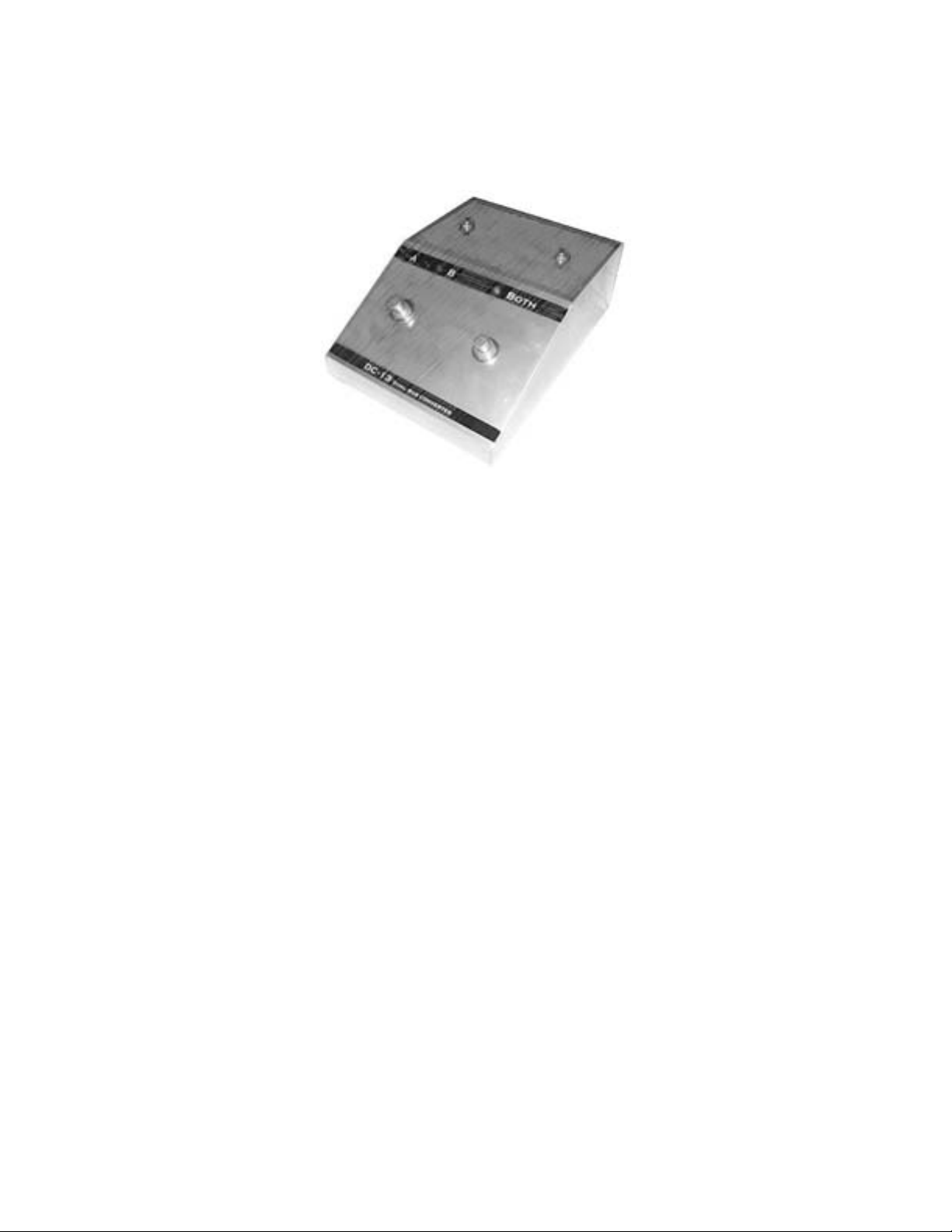
DC-13
Dual Bus Converter
OWNER’S MANUAL
_______________________________________
DESCRIPTION
Congratulations on your purchase of the DC-13
Dual Bus Converter.
The DC-13 combines the technology found in the
Roland BC-13 bus converter with technology
found in the Roland US-20 unit selector.
Like a BC-13 Bus Coverter, the DC-13 can
convert the vintage 24-pin style signals into
modern, 13-pin control signals, enabling the
vintage guitar synth enthusiast access to the
latest in guitar technology.
Like a US-20 Unit Selector, the DC-13 can be
used to select between two guitar synthesizers,
either individually or together.
In addition, the DC-13 has special separate
outputs for line-level guitar signal and hex fuzz.
Your DC-13 has been hand-built and hand-wired
using quality components for reliable operation
and is backed by a five-year warranty.
Please read this owner’s manual carefully before
using the DC-13.
_______________________________________
IMPORTANT NOTES
• The DC-13
does not
pass the output from
the guitar’s standard pickups to the 13-pin
synthesizer(s). To access the output from
the guitar’s pickups, use either the 1/4”
standard output jack on the guitar, or use
the direct Guitar Line Output on the DC-
13.
Page 2
• When connecting a guitar and
synthesizer(s) to the DC-13, be sure that
power to the synthesizer(s) is switched
off.
• The 13-pin connectors used with the DC13 are locking style, and therefore cables
cannot be disconnected unless the
locking pin is released.
• Due to the unique design of the VG-88, a
low level hum may be heard when the VG88 is used as Synth B. If this occurs, plug
the VG-88 into the Synth A jack.
_______________________________________
CONTENTS
1. Description
1. Important Notes
2. Contents
2. Panel Descriptions
3. Switch Functions
4. Synth Selection
4. Synth Selection (Both)
4. Specifications
_______________________________________
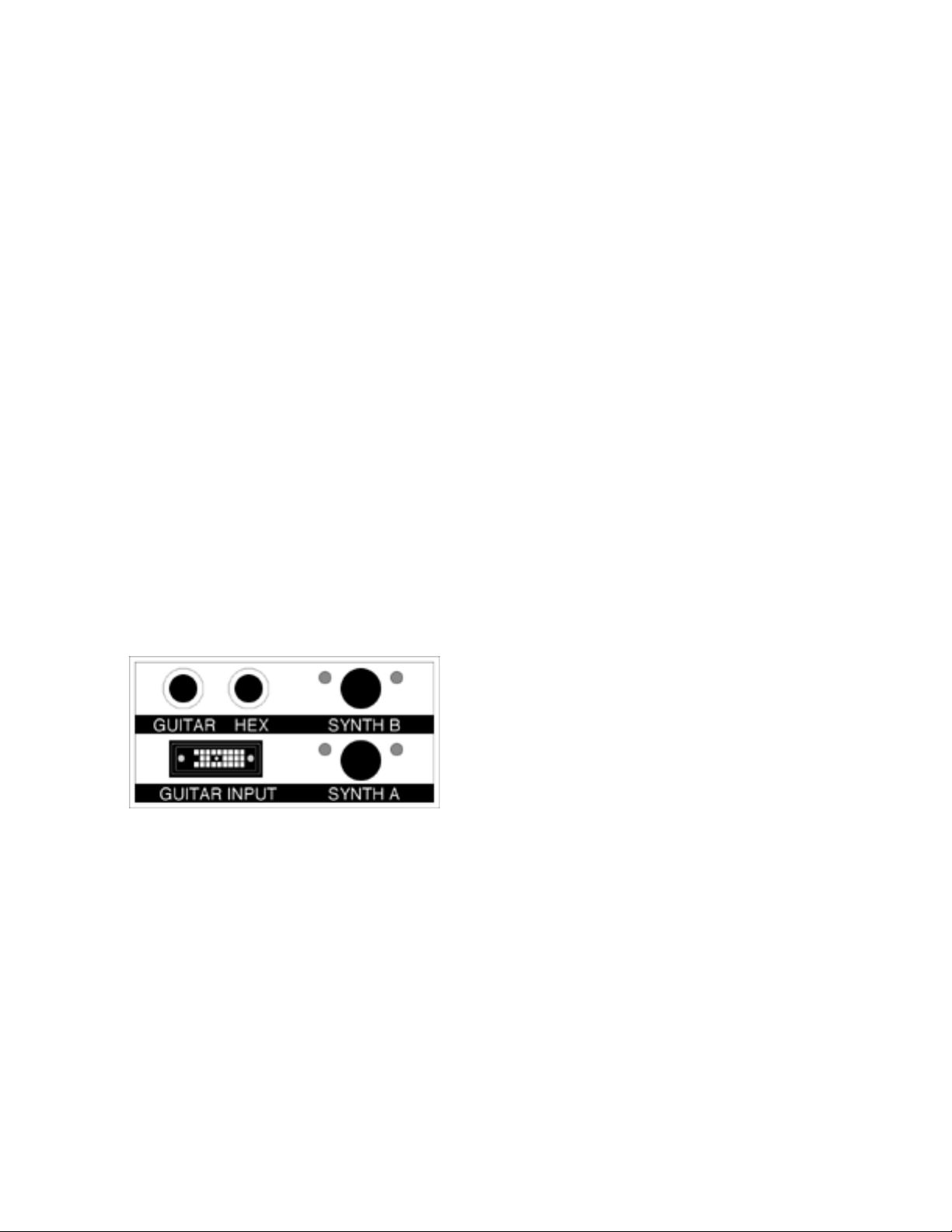
PANEL DESCRIPTIONS
1. Guitar Input: Input for 24-pin style G-
Series guitar cable.
2. Synth A Connector: The synthesizer
connected to this connector can be
played when [A] has been selected with
the [A/B] pedal switch on the top panel.
Please note that Synth A is also used as
the power source for the DC-13. Without
a device connected to the Synth A
connector, the DC-13 will not operate.
3. Synth B Connector: The synthesizer
connected to this connector can be
played when [B] has been selected with
the [A/B] pedal switch on the top panel.
4. [A/B] Pedal Switch: This is the pedal
switch that allows you to select which
device is to be played, either Synth A or
Synth B. If there is nothing connected to
the Synth B connector, the DC-13 will still
function as a BC-13 style 24 to 13 pin bus
converter.
5. [BOTH] Pedal Switch: When
switched ON, this pedal allows you to play
both of the synthesizers connected to
the DC-13.
6. Guitar Line Output: This connector
outputs the line-level guitar signal
generated by the pickups inside the
guitar. You can change the quality of this
sound by using the pickup selector switch
or the guitar’s tone control. This output
does not
respond to changes in volume
using the guitar’s master volume knob. If
Page 3

you want to vary the volume of the guitar
using the volume control on the guitar,
use the direct guitar output on the body
of the guitar itself. This is a standard 1/4”
jack usually found next to the 24-pin
connector on a G-series guitar.
7. Hex Fuzz: This connector outputs the
line-level hex fuzz distortion guitar signal
generated by the internal hex fuzz
circuitry inside a Roland G-202, G-303, G505, or G-808 guitar. Because this is a line
level signal, and because this is a
distorted signal, the output level is very
high. Like the Guitar Line Output, the Hex
Fuzz output
does not
respond to
changes in volume using the guitar’s
master volume knob.
_______________________________________
SWITCH FUNCTIONS
The DC-13 changes some the functions of
vintage G-Series controllers to match new, 13-pin
functions.
• Master Volume knob is now for Guitar
Volume only. This knob changes the
volume of the Guitar when a cable is
hooked to the standard 1/4” output jack
on the guitar.
• Guitar Tone Knob controls the tone of
the guitar’s normal sound.
• Filter Knob, or CV#1, becomes the
volume control for Synth A.
• Resonance Knob, or CV#2, becomes
the volume control for Synth B.
• Mode Switch becomes SW1 and SW2.
When the mode switch is switched down, the
receiving synth receives a “SWITCH 1” command.
When the mode switch is switch up, the receiving
synth receives a “SWITCH 2” command. This
function works best when the switch is rapidly
turned on and off, moving away from and quickly
returning to the center position (off).
The position for Mode I on a vintage G-Series
controller, is now “SWITCH 1.”
The position for Mode III on a vintage G-Series
controller, is now “SWITCH 2.”
The center position, or Mode II on a vintage GSeries controller, is now off.
[When using a G-Series Guitar]
G-202, 303, 505, 808
G-707
Page 4

Ibanez X-ING IMG2010
GK-1
_______________________________________
SYNTH SELECTION
Depress the [A/B] pedal, and the unit to be played
will change. You can tell whether Synth A or B is
currently selected by viewing the LED.
Red: The synth connected to Synth A is
selected.
Green: The synth connected to Synth B is
selected.
_______________________________________
SYNTH SELECTION WITH THE [BOTH] PEDAL SWITCH
Depress the [Both] pedal, and the LED will light in
yellow and both synths will be heard. However,
information about SW1 and SW2 (Mode Switch)
will be sent only to the device selected with the
[A/B] pedal switch.
Depress the pedal again, and the LED will go out
and only the device selected with the [A/B] pedal
switch will be heard.
_______________________________________
SPECIFICATIONS
DC-13 Dual Bus Converter:
• Connectors: One 24-pin input
connector, two 13-pin output connectors,
2 1/4” standard phone jacks for line-level
guitar and hex fuzz.
• Dimensions: 6(W) x 8(D) x 2 3/4(H)
inches
• Weight: 1 lbs 4 oz
© copyright March 2005
www.gr300.com
 Loading...