


Roland
Printed in Japan AI-2 (CR)
- 1
DISASSEMBLING/分解手順
*Turn the unit upside down when repairing. *修理時は下図の様に裏向けで分解して下さい。 0 22925660 1) 22925660 2) ⊖HOW TO REMOVE BOTTOM COVER 底板分解方法 22925657 3/3) ① A x 17 pcs 22925657 2/3) OHOW TO REMOVE KEYBOARD 鍵盤分解方法 1. Remove all the connectors on Main-A and B boards. 22925660 3) メインA,B基板上の全てのコネクターを外す。 2. ① C x 2 pcs 3. ① B x 3 pcs 4. ⑦ D x 2 pcs 5. Remove relative nylon cable ties. 関連のサブタイを外す。 22925657 1/3) 22925658) 22925659 1/3) 22925659 2/3) 5975 9715 9713 051200
EXPLODED VIEW /分解図
| 1 | MKS-10/30/80 Rubber Foot | 22355334 |
| 2 | Bottom | 21135180 |
| 3 | MAIN-A BOARD Assy | 7620434000 (pcb |
| 4 | MAIN-B BOARD Assy | 7620434000 (pcb |
| 5 | Keyboard Assy SK-376-DW | 7620420000 |
| 6 | JACK-A BOARD Assy | 7620409000 (pcb |
| 7 | Jack Holder | 22205245 |
| 8 | JACK-B BOARD Assy | 7620409000 (pcb |
| 9 | DIN Holder | 22205244 |
| 10 | A-50 Card Holder | 22205246 |
| 11 | MEMORY CARD BOARD | 7620434000 (pcb |
| 12 | Card Holder | 22200188 |
| 13 | Center Plate 212-260 | 22125260 |
| 14 | Center Plate B 212-275 | 22125275 |
| 15 | LCD Unit TLX-711A-30TA1 | 15029483 |
| 16 | LCD Holder | 22205242 |
| 17 | SWITCH-A BOARD Assy | 7620409000 (pcb |
| 18 | SWITCH-B BOARD Assy | 7620412000 (pcb |
| 19 | LCD Cover | 22045164 |
| 20 | Escutcheon | 22225332 |
| 21 | Bender Wheel Assy BW-A0000 | 23275893 |
| 22 | Bender Lever Assy PB-A0102 | 23275892 |
| 23 | Side Plate L | 22125263 |
| 24 | Side Board L | 21125334 |
| 25 | Side Plate R | 22125262 |
| 26 | POWER SUPPLY BOARD Assy | 7620430000 (pcb |
| 27 | Power Trans. | 22455548U0 |
| 28 | FILTER BOARD Assy | 7620430000 (pcb |
| 29 | AC Inlet CM-11 (3P) | 13429718 |
| 30 | POWER Switch WK2A44 | 13149108 |
| 31 | Selector Switch ESE-3711 | 13169503 |
| 32 | Side Board R | 21125333 |
| 33 | Panel | 22215616 |
| А | Machine Binding | M4 x 6 | вс | |
| В | B. Tight Binding | M3 × 6 | Cm | |
| С | Tapping Binding | M3 x 6 B1 | BC | |
| D | Tapping Binding | M3 x 12 B1 | Cm | |
| Е | Tapping Binding | M3 x 10 A1 | Cm | |
| F | Machine Binding | M3 x 8 | вс | |
| G | P. Tight Pan | M3 x 8 | Cm | |
| н | Tapping Binding | M3 x 8 A1 | Cm | |
| ł | Machine Binding | M3 x 4 | Cm | |
| J | Tapping Binding | M3 x 12 B1 | Cm | |
| К | Machine Binding | M4 x 6 | Cm | |
| L | Machine Binding | M3 x 10 | вс | |
| М | Tapping Binding | M3 x 8 B1 | вс | |
| Ν | Machine Binding | M3 x 12 | Cm | |
| 0 | HP-800 Power Tr Hol | der | 22195 | |
| Ρ | Bushing | TB-300 BLK | 12159 | |
| Q | Collar | TA-305P | 12159 | |
| R | Standoff 6 mm | M3 x 6 | 22150 | |
| S | Machine Sems | M3 x 4 | вс | |
| т | PCB Holder | KGLS-8S-V0 | 12199 | |
| U | Flange Nut | M3 | Cm | |
| v | Jack Nut | N12 | вс | |
| W | Tapping Binding | M3 x 6 B1 | Cm. | |
| х | Tapping Flat | M3 x 6 B1 | вс |
FEB, 1989
PARTS LIST
| mining | , procession and the second se | |
|---|---|---|
| SAFETY PRECAUTIONS: | CONSIDERATIONS ON PARTS ORDERING | |
|
The parts marked ▲ have
safety-related characteristics. Use only listed parts for replacement. 安全上の注意: ▲が付いている部品は、安全上 |
When ordering any parts listed in the parts list, plea
OTY PART NUMBER Ex. 10 22575241 15 2247017300 Failure to completely fill the above items with corre even undelivered replacement. パーツ発注に関するお願い |
se specify the following items in the order sheet.
DESCRIPTION MODEL NUMBER Sharp Key C-20/50 Knob (orange) DAC-15D ct number and description will result in delayed or |
|
特別な規格でつくられたもので
す。 交換の際は,指定された部品番 号以外の部品は使わないように して下さい。 |
★ オーダーシートには、必ず下記の4項目は正確に記入
必要数 パーツナンバー 例) 10 22575241 15 2247017300 もし記入漏れ,誤記等が有る場合,必要部品が発送出 御協力をお願いします。 |
して下さい。(例外は除く)
品名名 使用機種 Sharp Key C-20/50 Knob (orange) DAC-15D 来なかったり、大幅な遅れの原因になります。 |
CABINET キャビネット
| 21125180 | Bottom | 1 | |
|---|---|---|---|
| 21135180 | Bollom | ||
| 22215616 | Panel | ||
| 21125333 | Side Board R | ||
| 21125334 | Side Board L | ||
| 22125260 | Center Plate 212-260 | ||
| 22125262 | Side Plate R | ||
| 22125263 | Side Plate L | ||
| 22125275 | Center Plate B 212-275 | ||
| 22025413 | P. Cover | ||
| 22045164 | LCD Cover | LCD カバー | |
| 22225332 | Escutcheon | エスカッション | |
| 22355334 | MKS-10/30/80 Rubber Foot | ゴム足 |
HOLDER ホルダー
| Holder KGLS-8S-V0 | FILTER | |
|---|---|---|
| Holder | SWITCH-A | |
| Holder | JACK-B | |
| k Holder | JACK-A | |
| 0 Card Holder | MEMORY CARD | |
| d Holder | MEMORY CARD | |
| 800 Power Tr Holder | ||
| I-1 Battery Retainer | MAIN-B | |
|
Holder KGLS-8S-V0
Holder Holder Card Holder Holder Holder 300 Power Tr Holder |
Holder KGLS-8S-V0FILTERHolderSWITCH-AHolderJACK-BKolderJACK-ACard HolderMEMORY CARDHolderMEMORY CARD300 Power Tr HolderMAIN-B |
BUTTON, KNOB ボタン, ツマミ
| 22475656 | S-10 Button D (single) black with LED window |
|---|---|
| 22475658 | S-10 Button S (single) black |
| 22495577 | A-50 Button D (single) gray with LED window |
| 22485126 | RD-300 Knob |
SWITCH スイッチ
|
13149108
13169503 13169693 |
WK2A44
ESE-3711 SKHHDC |
POWER Switch
Selector Switch Tact Switch |
|
|---|---|---|---|
| JACK, SOCKET | ジャック,ソケット | ||
| 13449275 | YKB-21-5074 | Mono Jack | JACK-A |
| 13429642 | M-S2-3P | MIDI Socket | JACK-B |
| 13429525 | IS28B0BCT | IC Socket | MAIN-A, MAIN-B |
| 13429233 | 7508095A | IC Card Connector | MEMORY CARD |
| POTENTIOMET | ER ボリューム | ||
| 13339476 | EWA-NP5X10B14 | CONTROLLER (slide) | |
| 13279810 | EVJ-ELA-E02B14 | LCD CONTRAST (trimmer) | |
| イル | |||
| 12449229 | FK013-160MH15 | Line Filter Coil | FILTER |
| 12449584 | D32-49 | EL Trans. | POWER SUPPLY |
| 22445240 | BL02RN2-R62 | Ferrite bead | MAIN-A, MAIN-B |
| CRYSTAL 発揚 | 表子 | ||
| 12389747 | HC-49/U | 16MHz |
PCB ASSEMBLY 基板完成品
| /620409000 |
SWITCH-A BOARD Assy
Replacement Switch-A Boa 補修用スイッチ A 基板は下言 |
PCB 22925657 (1/3)
rd Assy includes the following: この 2 点を含みます。 |
||
|---|---|---|---|---|
|
JACK-B BOARD Assy
JACK-A BOARD Assy |
PCB 22925657 (2/3)
PCb 22925657 (3/3) |
le de la companya de
La companya de la comp |
||
| and the second | ||||
| 7620412000 | SWITCH-B BOARD Assy | PCB 22925658 | ||
| 7620430000 | Assy | PCB 22925059 (1/5) | ||
| Replacement Power Supply | Board Assy includes the follow | ving: | ||
| 補修用電源基板は下記の2点 | を含みます。 | |||
| PCB 22925659 (2/3) | ||||
| PCB 22925659 (3/3) | ||||
| 7620434000 | MAIN-A BOARD Assy | PCB 22925660 (1) | ||
| Replacement Main-A Board | Assy includes the following: | and the second | ||
| 補修用メイン A 基板は下記の | )2点を含みます。 | 4 | ||
| MAIN-B BOARD Assy | PCB 22925660 (2) | |||
| PCB 22925660 (3) | ||||
| KEYBOARD 鍵盤 | . | |||
| 7620420000 | SK-376-DW | 76key | ||
| ACINLET AC 1 | ンレット |
-
- 2 |
||
| 13429718 | CM-11 (3P) | AC Inlet | ||
| AC CORD (Detach | able) AC コード(着脱式) | |||
| 1 12 | DC-015-J01 | 100V | ||
| 13499109 | UC-909-J06 | 117V | - | |
| ∧ 23495125 | EC-752-E02 | 220V | ||
| 5722-660-4606 | 240V-England | ۶. | ||
| /∆23495124 | SC-405-J01 | 240V-Australian | 1.1 | |
| POWER TRANSFO | DRMER トランス |
- 11
|
||
| ∆22455548U0 | Power Trans. | universal | ||
| BENDER UNIT | ベンダー | .r | ||
| 23275892 | PB-A0102 | Bender Lever Assy | ||
| 23275893 | BW-A0000 | Bender Wheel Assy | ||
| LCD UNIT LCD | ユニット | |||
| 15029483 | ||||
| TLX-711A-30TA1 | ||||
|
TLX-711A-30TA1
No replacement for individu |
ual parts. | |||
|
TLX-711A-30TA1
No replacement for individe 補修用はユニット単位。 |
ual parts. | |||
|
TLX-711A-30TA1
No replacement for individu 補修用はユニット単位。 ~デンサー |
ual parts. | |||
| CAPACITOR ⊐ > ▲13529104 □ |
TLX-711A-30TA1
No replacement for individe 補修用はユニット単位。 ・デンサー DE7150F472MVA1 |
ual parts. | line bypass | |
|
CAPACITOR
コン
▲13529104 13659213M0 |
TLX-711A-30TA1
No replacement for individu 補修用はユニット単位。 ~デンサー DE7150F472MVA1 ECET25R472SW |
ual parts.
4700 µ F 25V |
line bypass
electro |
|
|
CAPACITOR ⊐ >
▲13529104 13659213M0 13649145 |
TLX-711A-30TA1
No replacement for individu 補修用はユニット単位。 - デンサー DE7150F472MVA1 ECET25R472SW 50MV1000HA4 |
ual parts.
4700 µ F 25V 1000 µ F 50V |
line bypass
electro electro |
|
|
CAPACITOR ⊐ 2
▲13529104 13659213M0 13649145 13649146 |
TLX-711A-30TA1
No replacement for individu 補修用はユニット単位。 - デンサー DE7150F472MVA1 ECET25R472SW 50MV1000HA4 50MV2200HA4 |
ual parts.
4700 μ F 25V 1000 μ F 50V 2200 μ F 50V |
line bypass
electro electro electro |
|
|
CAPACITOR ⊐ 2
▲13529104 13659213M0 13649145 13649146 13639676 |
TLX-711A-30TA1
No replacement for individu 補修用はユニット単位。 ・デンサー DE7150F472MVA1 ECET25R472SW 50MV1000HA4 50MV2200HA4 SRA10V100TP |
ual parts.
4700 μ F 25V 1000 μ F 50V 2200 μ F 50V 100 μ F 10V |
line bypass
electro electro electro electro small type |
|
|
CAPACITOR ⊐>
▲13529104 13659213M0 13649145 13649146 13639676 13629149J0 13629149J0 |
TLX-711A-30TA1
No replacement for individu 補修用はユニット単位。 - デンサー DE7150F472MVA1 ECET25R472SW 50MV1000HA4 50MV2200HA4 SRA10V100TP SRA16VB47 SRA16VB47 |
ual parts.
4700 μ F 25V 1000 μ F 50V 2200 μ F 50V 100 μ F 10V 47 μ F 16V |
line bypass
electro electro electro electro small type electro small type |
|
|
CAPACITOR ⊐>
▲13529104 13659213M0 13649145 13649146 13639676 13629149J0 13639678J0 13639678J0 |
TLX-711A-30TA1
No replacement for individu 補修用はユニット単位。 -デンサー DE7150F472MVA1 ECET25R472SW 50MV1000HA4 50MV2200HA4 SRA10V100TP SRA16VB47 SRA16VB10TP |
ual parts.
4700 μ F 25V 1000 μ F 50V 2200 μ F 50V 100 μ F 10V 47 μ F 16V 10 μ F 16V 6 9 μ F 25V |
line bypass
electro electro electro small type electro small type electro small type |
|
|
CAPACITOR ☐>
▲13529104 13659213M0 13649145 13649146 13639676 13629149J0 13639678J0 13639684 13639684 |
TLX-711A-30TA1
No replacement for individu 補修用はユニット単位。 - デンサー DE7150F472MVA1 ECET25R472SW 50MV1000HA4 50MV2200HA4 SRA10V100TP SRA16VB47 SRA16VB47 SRA16VB10TP KMA25V6.8TP SPA50VP2P2 |
ual parts.
4700 μ F 25V 1000 μ F 50V 2200 μ F 50V 100 μ F 10V 47 μ F 16V 10 μ F 16V 6.8 μ F 25V 2 2 μ F 50V |
line bypass
electro electro electro small type electro small type electro small type electro small type electro small type |
|
|
CAPACITOR ☐>>
▲13529104 13659213M0 13649145 13649146 13639676 13629149J0 13639678J0 13639684 13629203J0 12629695 I0 |
TLX-711A-30TA1
No replacement for individu 補修用はユニット単位。 ~デンサー DE7150F472MVA1 ECET25R472SW 50MV1000HA4 50MV2200HA4 SRA10V100TP SRA16VB47 SRA16VB10TP KMA25V6.8TP SRA50VB2R2 SRA50VB2R2 SRA50VB1TP |
4700 μ F 25V
1000 μ F 25V 2200 μ F 50V 2200 μ F 50V 100 μ F 10V 47 μ F 16V 10 μ F 16V 6.8 μ F 25V 2.2 μ F 50V |
line bypass
electro electro electro small type electro small type electro small type electro small type electro small type electro small type |
|
|
CAPACITOR ☐
13529104 13659213M0 13649145 13649146 13639676 13629149J0 13639678J0 13639684 13629203J0 13639695J0 13639694 |
TLX-711A-30TA1
No replacement for individu 補修用はユニット単位。 - デンサー DE7150F472MVA1 ECET25R472SW 50MV1000HA4 50MV2200HA4 SRA10V100TP SRA16VB47 SRA16VB10TP KMA25V6.8TP SRA50VB2R2 SRA50VB1TP SRA50VR47TP |
4700 μ F 25V
1000 μ F 25V 2200 μ F 50V 2200 μ F 50V 100 μ F 10V 47 μ F 16V 10 μ F 16V 6.8 μ F 25V 2.2 μ F 50V 1 μ F 50V 0.47 μ F 50V |
line bypass
electro electro electro small type electro small type electro small type electro small type electro small type electro small type electro small type electro small type |
|
|
CAPACITOR □ン
▲13529104 13659213M0 13649145 13649146 13639676 13629149J0 13639678J0 13639684 13629203J0 13639695J0 13639694 DIODE ダイオー |
TLX-711A-30TA1
No replacement for individu 補修用はユニット単位。 /デンサー DE7150F472MVA1 ECET25R472SW 50MV1000HA4 50MV2200HA4 SRA10V100TP SRA16VB47 SRA16VB10TP KMA25V6.8TP SRA50VB2R2 SRA50VB1TP SRA50VR47TP |
4700 μ F 25V
1000 μ F 25V 2200 μ F 50V 2200 μ F 50V 100 μ F 10V 47 μ F 16V 10 μ F 16V 6.8 μ F 25V 2.2 μ F 50V 1 μ F 50V 0.47 μ F 50V |
line bypass
electro electro electro small type electro small type electro small type electro small type electro small type electro small type electro small type |
|
|
CAPACITOR コン
▲13529104 13659213M0 13649145 13649146 13639676 13629149J0 13639678J0 13639678J0 13639684 13629203J0 13639695J0 13639695J0 13639694 DIODE ダイオー ▲15019272 |
TLX-711A-30TA1
No replacement for individu 補修用はユニット単位。 > デンサー DE7150F472MVA1 ECET25R472SW 50MV1000HA4 50MV2200HA4 SRA10V100TP SRA16VB47 SRA16VB10TP KMA25V6.8TP SRA50VB2R2 SRA50VB2R2 SRA50VB1TP SRA50VR47TP ド 2B4B41 |
4700 μ F 25V
1000 μ F 25V 2200 μ F 50V 2200 μ F 50V 100 μ F 10V 47 μ F 16V 6.8 μ F 25V 2.2 μ F 50V 1 μ F 50V 0.47 μ F 50V |
line bypass
electro electro electro small type electro small type electro small type electro small type electro small type electro small type electro small type electro small type electro small type |
|
|
CAPACITOR コン
▲13529104 13659213M0 13649145 13649146 13639676 13629149J0 13639678J0 13639678J0 13639684 13629203J0 13639695J0 13639695J0 13639694 DIODE ダイオー ▲15019272 ▲15019272 |
TLX-711A-30TA1
No replacement for individu 補修用はユニット単位。 - デンサー DE7150F472MVA1 ECET25R472SW 50MV1000HA4 50MV2200HA4 SRA10V100TP SRA16VB47 SRA16VB47 SRA16VB10TP KMA25V6.8TP SRA50VB2R2 SRA50VB1TP SRA50VB1TP SRA50VR47TP ド 2B4B41 S1VB10 |
ual parts.
4700 μ F 25V 1000 μ F 50V 2200 μ F 50V 100 μ F 10V 47 μ F 16V 10 μ F 16V 6.8 μ F 25V 2.2 μ F 50V 1 μ F 50V 0.47 μ F 50V 100V 2A 100V 1A |
line bypass
electro electro electro small type electro small type electro small type electro small type electro small type electro small type electro small type electro small type electro small type electro small type |
|
|
CAPACITOR コン
▲13529104 13659213M0 13649145 13649146 13639676 13629149J0 13639678J0 13639678J0 13639684 13629203J0 13639695J0 13639695J0 13639694 DIODE ダイオー ▲15019272 ▲15019245SN 15019152T0 |
TLX-711A-30TA1
No replacement for individu 補修用はユニット単位。 、 デンサー DE7150F472MVA1 ECET25R472SW 50MV1000HA4 50MV2200HA4 SRA10V100TP SRA16VB47 SRA16VB47 SRA16VB10TP KMA25V6.8TP SRA50VB2R2 SRA50VB2R2 SRA50VB1TP SRA50VB1TP SRA50VR47TP ド 2B4B41 S1VB10 1SS176 TPA-7 |
ual parts.
4700 μ F 25V 1000 μ F 50V 2200 μ F 50V 100 μ F 10V 47 μ F 16V 10 μ F 16V 6.8 μ F 25V 2.2 μ F 50V 1 μ F 50V 0.47 μ F 50V 100V 2A 100V 1A |
line bypass
electro electro electro small type electro small type electro small type electro small type electro small type electro small type electro small type electro small type electro small type electro small type |
|
|
CAPACITOR コン
▲13529104 13659213M0 13649145 13649146 13639676 13629149J0 13639678J0 13639678J0 13639694 DIODE ダイオー ▲15019272 ▲15019272 ▲15019245SN 15019152T0 15019281 |
TLX-711A-30TA1
No replacement for individu 補修用はユニット単位。 /デンサー DE7150F472MVA1 ECET25R472SW 50MV1000HA4 50MV2200HA4 SRA10V100TP SRA16VB47 SRA16VB10TP KMA25V6.8TP SRA50VB2R2 SRA50VB1TP SRA50VB1TP SRA50VR47TP ド 2B4B41 S1VB10 1SS176 TPA-7 1SR-35-100 T-93 |
4700 μ F 25V
1000 μ F 25V 2200 μ F 50V 2200 μ F 50V 100 μ F 10V 47 μ F 16V 10 μ F 16V 6.8 μ F 25V 2.2 μ F 50V 1 μ F 50V 0.47 μ F 50V 100V 2A 100V 2A 100V 1A |
line bypass
electro electro electro small type electro small type electro small type electro small type electro small type electro small type electro small type electro small type electro small type |
|
|
CAPACITOR コン
▲13529104 13659213M0 13649145 13649146 13639676 13629149J0 13639678J0 13639678J0 13639694 DIODE ダイオー ▲15019272 ▲15019272 ▲15019245SN 15019152T0 15019281 15019514 |
TLX-711A-30TA1
No replacement for individu 補修用はユニット単位。 /デンサー DE7150F472MVA1 ECET25R472SW 50MV1000HA4 50MV2200HA4 SRA10V100TP SRA16VB47 SRA16VB10TP KMA25V6.8TP SRA50VB2R2 SRA50VB2R2 SRA50VB1TP SRA50VR47TP ド 2B4B41 S1VB10 1SS176 TPA-7 1SR-35-100 T-93 05AZ-7.5Z |
4700 μ F 25V
1000 μ F 25V 2200 μ F 50V 2200 μ F 50V 100 μ F 10V 47 μ F 16V 6.8 μ F 25V 2.2 μ F 50V 1 μ F 50V 0.47 μ F 50V 100V 2A 100V 2A 100V 1A |
line bypass
electro electro electro small type electro small type electro small type electro small type electro small type electro small type electro small type electro small type electro small type electro small type |
IC
| 15179203 | HD63B03RP | CPU | MAIN-A, MAIN-B | |
| 15179799F0 | MB27C-128-20 | EPROM (ROM A) IC2 | MAIN-A | |
| 15179789B0 | M5M27C256K-15 | EPROM (ROM B) IC13 | MAIN-B | |
| 15179343F0 | MB8416A-12P-SK-G | SRAM | MAIN-A | |
| 15179374H0 | HM62256LP-12 | SRAM | MAIN-B | |
| 15159503 | TC40H000P | Quad 2-input NAND Gate | MAIN-A | |
| 15159514 | TC40H032P | Quad 2-input OR Gate | MAIN-A | |
| 15159528T0 | TC40H008P | Quad 2-input AND Gate | MAIN-B | |
| 15169513 | TC74HC74P | Dual D Flip Fiop with Preset | MAIN-A | |
| and Clear | ||||
| 15169554T0 | TC74HC374P | Octal D-type Flip Flop with | MAIN-A | |
| 3-state Outputs | ||||
| 15169563 | TC74HC244P | Non-inverted, 3-state Outputs | MAIN-A | |
| 15169515 | TC74HC00P | Quad 2-input NAND Gate | MAIN-B | |
| 15169514 | TC74HC04P | Hex Inverter | MAIN-B | |
| 15169549T0 | TC74HC32P | Quad 2-input OR Gate | MAIN-B | |
| 15169539 | TC74HC139P | Dual 2-to-4 Line Decoder | MAIN-B | |
| 15169543 | TC74HC373P | Octal D-type Latch with 3-state | MAIN-B | |
| Output (non inverting) | ||||
| 15169598 | TC74HC541P | Octal Bus Buffer (non | MAIN-B | |
| - | inverting) | |||
| 15169550T0 | TC74HC138P | 3-to-8 Line Decoder | SWITCH-A | |
| 15159113T0 | TC4051BP | 8-channel Analog Multiplexer | MAIN-A, SWITCH-A | |
| 15169318B0 | M74LS138P | 3-line-to-8 Line Decorder | MAIN-A | |
| 15169346B0 | M74LS03P | Quadruple 2-input Positive | JACK-B | |
| NAND Gates | ||||
| 15209107 | BA9101 | A/D Converter | MAIN-A | |
| 15229830 | MB63H149PF-G-BND | Gate Array | MAIN-A | |
| 15229864 | μ PD65005G-124-12 | Gate Array R06-0004 | MAIN-A, MAIN-B | |
| 15229848 | μ PD65005G-062 | Gate Array | MAIN-B | |
| 15229706S0 | PC-910 | Optoislator | JACK-B | |
| 15189147 | NJM-072D | Op. AMP | MAIN-A | |
| 15189189 | μ PC4570HA | Op. AMP | SWITCH-A | |
| Δ | 15199108N0 | μ PC78M05H | V. Ragulator +5V | POWER SUPPLY |
| ⚠ | 15199176 | L78M12ML | V. Ragulator +12V | POWER SUPPLY |
| ⚠ | ∆15199177 | L79M12ML | V. Ragulator — 12V | POWER SUPPLY |
TRANSISTOR トランジスタ
| 15119134 | 2SA933S DCTPR |
|---|---|
| 15129153 | 2SC1740S DCTPR |
| 15129168 | DTC124ES-TP |
| 15129197 | DTC144WS-TP |
| 15129198 | DTA124ES-TP |
| 15139121 | 2SK117GT FET |
RESISTOR ARRAY 抵抗アレイ
| 13919140 | RGLD 8X10³J | 10kΩ × 8 | MAIN-A, MAIN-B | |
|---|---|---|---|---|
| 13919142 | RGLD 8X10⁴J | 100kΩ x 8 | ||
| 13919182 | RGLD 10X333J | 33kΩ x 10 | MAIN-A | |
| 13919183 | RGLD 12X333J | 33kΩ x 12 | MAIN-A | |
| CAPACITOR AR | RAY コンデンサーアレ | 1 | · | |
| 13529147 | CXKD 8X101M | 100pF x 8 | MAIN-A | |
| 13529151 | CXKD 4X220K | 22pF x 4 | MAIN-A | |
| 13529152 | CXKD 6X220K | 22pF x 6 | MAIN-A | |
| BATTERY バッ | テリー |
| nan in the second s | ||||
|---|---|---|---|---|
| 125692 | 49 | CR2032 Leadless | Lithium | |
| OTHERS | その他 | |||
| 121597 | 13 | TA-305P | Collar | |
| 121597 | 15 | TB-300 BLK | Bushing |
KEYBOARD ASS'Y SK-376-DW ASSY 7620420000
| No. | PARTS No. | PARTS NAME |
|---|---|---|
| 22575136 | SK-3 NATURAL KEY C, F 257-136 | |
| 22575137 | SK-3 NATURAL KEY D 257-137 | |
| 22575135 | SK-3 NATURAL KEY E, B 257-135 | |
| 1 | 22575138 | SK-3 NATURAL KEY G 257-138 |
| 22575134 | SK-3 NATURAL KEY A 257-134 | |
| 22575191 | SK-3 NATURAL KEY E' 257-191 | |
| 22575141 | SK-3 NATURAL KEY G' 257-141 | |
| 2 | 22575243 | SK-3 SHARP KEY P 257-243 |
| 3 | 22815652 | A-50 SK-3 CHASSIS 76P 281-652 |
| 4 | 22265453 | SK-3 FELT 226-453 |
| 5 | 22155716 | HP GUIDE BUSH 215-716 |
| 6 | (22175176) | SK-3 SPRING(NATURAL KEY) 217-176 🖈 |
| (22175177) | SK-3 SPRING(SHARP KEY) 217-177 ★ | |
| 7 | 22185218 | SK-3 CONTACT RUBBER 12PW 218-218 |
| Q | 22245146 | SK-3 SWITCH COVER 24P 224-146 |
| Ů | 22245147 | SK-3 SWITCH COVER 28P 224-147 |
| 7620022000 | SK-376-CW CONTACT P.C.B 24P LOW ASSY | |
| 9 | 7620023000 | SK-376-CW CONTACT P.C.B 24P MID ASSY |
| 7620024000 | SK-376-CW CONTACT P.C.B 28P HI ASSY | |
| 10 | 22135415 | SK-3 STOPPER A 213-415 |
| 22135418 | SK-3 STOPPER D 213-418 | |
| 11 | 22125603 | A-50 SK-3 ANGLE 1 212-603 |
| 12 | 22125604 | A-50 SK-3 ANGLE 2 212-604 |
| 13 | 22125541 | SK-3 ANGLE B-JX 212-541 |
| 23165690 | SK-3 AFTER TOUCH P.C.B 24P ASSY 316-690 (MID) | |
| 14 | 23165691 | SK-3 AFTER TOUCH P.C.B 25P ASSY 316-691 (LOW) |
| 23165692 | SK-3 AFTER TOUCH P.C.B 27P ASSY 316-692(HI) | |
| 13479261 | SMCD-19X160-BDX10(2.7)-P1.25 | |
| 15 | 13479260 | SMCD-16X70-BDX10(2.7)-P1.25 |
| 13479259 | SMCD-13X60-BDX10(2.7)-P1.25 | |
| 16 | 22205243 | AD-06B K.HOLDER 220-243 |
| 17 | NILON RIVET NRP-345 🛠 | |
| 18 | TAPPING SCREWS 3X8 B1 |

4-50
DATA SAVE/LOAD
SAVE
Saving A-50 memory to RAM CARD
SAVE saves the contents of the A-50 onto the 32k byte BAM card (M-256D M-256E; optional) The previous contents of the RAM card is lost. The entire A-50 memory is SAVED Patches or Chains may not be individually saved.
Procedure to save onto a BAM card
STEP 1 Press Utilit. in the ROLAND menu. STEP 2 Insert a memory card into the card slot. STEP 3 Turn RAM card protect switch to OFE.
データ セーブ/ロード
セーブ
A-50からメモリー・カードへのセーブ
ここで言うセーブとは A.50のデータを32k バイトの RAM カード (M 256D 256F・別売) に読み込ませることです ヤーブを行なうとメモリー・カードトのデータは全て失われ ます。
A-50のセーブは、全てのデータに対して行なわれます。パッ チやチェイン単位のセーブはできません。
【A-50からメモリー・カードヘセーブする方法】
操作1 ローランドメニューから Utility を押します。 操作2 メモリー・カードをカード・スロットに挿入しま す 操作3 メモリー・カードのプロテクト・スイッチをオフに します。

STEP 4 Select the SAVE menu
操作4 セーブ・メニューを選びます。

- STEP 5 To "OK" press YES (Entering NO at any prompt will go back to . "OK")
- STEP 6 To "Are you sure?" press YES Now the entire data is saved onto the card.
- STEP 7 Return RAM card protect switch to ON.
操作5 "OK"表示に対して、 YES を押します。 (ON を押すといつでも"OK"に戻ります。) "Are you sure?"と尋ねてきます。正しければ 操作 6 VFS ボタンを押します。 これでカードへセーブできます。 操作7 メモリー・カードのプロテクト・スイッチをオンに
1 ます.
コード
Data Transfer via MIDI
STEP 4 To "OK" press YES
STEP 5 To "Are you sure?" press YES
"OK")
Using the Roland System Exclusive messages, the A-50's data can be transferred to another A-50 or MIDI sequencer, etc. The A-50's data transfer is performed in a One Way method that transmits data without confirming the status of the receiver.
Data Transfer to a MIDI sequencer (Bulk Dump)
Pr

Use One-way setups.
MIDI によるデータの転送
ローランドのエクスクルーシブ・メッセージを使って他の MIDI 機器にデータをひとまとめにして転送することができ ます。データの転送はワンウェイ方式で行ないます。ワンウェ イでは、受信側の状態に関わらず一方的にデータを転送しま す。
他の MIDI 機器への転送(バルク・ダンプと呼びます)
Loading A-50 memory from RAM CARD
Load, loads the contents of the 32k byte RAM card (M-256D, M-256F: optional) into the A-50. The previous contents of the A-50 memory is lost. The entire A-50 memory is LOADED. Patches or Chains may not be individually loaded.
- To use a brand new memory card first save the entire data in the A-50 onto the card.
- The RAM card is for A-50 backup only. It does not increase the number of simultaneously available Patches or Chains
メモリー・カードから A-50へのロード
ここで言うロードとは、32k バイトの RAM カード (M-256D. 256E: 別売)のデータを A-50に読み込ませることです。 ロードを行たうと A-50内部 メモリートのデータは全て失わ
- A-50のロードは、全てのデータに対して行なわれます。ブ ロック単位のロードはできません。
- *新しくメモリー・カードを使う場合は、あらかじめ【セー ブ】の操作で、本体の全てのデータをカードに記憶させて からでないと、ライト操作で記憶することはできません。 * × モリー・カードは 4.50のバックアップにのみ使用でき ます。メモリー・カードで、同時に使用するパッチやチェ インの数を増やすことはできません。

| Procedure to dump the A-50's memory: | |
|---|---|
| STEP 1 Press Utility menu in the ROLAND m | nenu. |
| STEP 2 Press .BDump. |
【バルク・ダンプの方法】 操作1 ローランド・メニューからユーティリティ・メ ニュー・キーを押します。 操作2 .B. Dump. を押します。
|
Bulk
Ok |
Dump | System | Exclusive | ?( | Yes∕no | ~ |
|---|---|---|---|---|---|---|
| ave l | oad Col | 9y |
Procedure to load from the RAM card:
STEP 1 Insert the memory card into the card slot. An "Illegal Card" message indicates that the RAM card has data saved by a device other than the A-50 or that the card has not had any data saved to it previously. Replace it with a proper card STEP 2 Press Utility in the ROLAND menu. STEP 3 Press Load.
(Entering "No" at any prompt will go back to
Now the entire data is loaded into the A-50
【メモリー・カードから A-50のメモリーへロードする方法】 握作1 メモリー・カードをカード・スロットに挿入しす す。 。 *データが書き込まれていないメモリー・カード や A-50以外のメモリー・カードから データ をロードしようとすると"Illegal Card"の表示が 表われます。メモリー・カードを正しいものと交 換してください。
操作2 ローランド・メニューから Utilit. を押します。
操作4 "OK"表示に対して、 YES を押します。
YES ボタンを押します。
(ON を押すといつでも "OK" に戻ります。)
これでカードの内容がロードされます。
"Are vou sure?"と尋ねてきます。正しければ

from Memory Card ? ( yes/no )
操作 6
- STEP 3 To "OK" press YES.
-
(Entering NO at any prompt will go hack to "OK") STEP 4 To "Are you sure?" press YES. The data will be sent out to the currently enable MIDI outputs.
- The Dump will take several seconds.
Data Transfer from a MIDI sequencer (Bulk Load)

-
操作6 "Are you sure?"と尋ねてきます。正しければ YES ボタンを押します。 これで、データは MIDI アウトから送信されます。
- 転送が終わるのに数秒かかります。
他の MIDI 機器からの転送(バルク・ロードと呼びます)

Procedure for loading Exclusive data:
The transfer procedure is controlled from the transmitting side. You do not need to operate the receiving A-50. However, to receive its own Bulk data, the A-50 must be set to recognize the System Exclusive from MIDI IN 1. (Exclusive Receive ON)
There is no Load Bulk Dump menu as this is handled automatically.
The receiving A-50 will display "Exclusive Loaded" at the completion of the dump if no error occurred. An appropreate error message will appear indicating the location of the data error:
"Error in Chan. Name": the error occurred in an Exclusive block describing the assigned MIDI channel names.
"Error in Chain Load": the error occurred in an Exclusive block describing the Chains.
"Error in Patch Load": the error occurred in an Exclusive block describing the 64 A-50 Patches. "Error in Bulk Library": the error occurred in an Exclusive block describing the Bulk Library data.
A-50にはバルク・ダンプを受けとるためのバルク・ロード・メニューはありません。MIDIオプションの『エクスクルシーブの受信』の設定がオンになっていれば,MIDIイン1からはいってきた自分のデータを判別して自動的にバルク・ロードします。転送がうまく行くと"Exclusive Loaded"の文字がディスプレイに現われます。
* データ・エラーを起こした場合,次の様なエラー・メッ セージが表示され,エラーを起こした箇所の確認ができま す。
"Error in Chan Name": MIDI チャンネル・ネームでのエラー "Error in Chan Load": チェインでのエラー "Error in Patch Load": パッチでのエラー "Error in Bulk Library": バルク・ライブラリー・データでのエラー
TEST MODE
The test mode is also provided with procedures allowing the testing of internal RAM. However, as a result the user's settings will be destroyed. Before entering the test mode make certain you have first made a backup onto Ram Card.
(Refer to page 5 and 6.)

TEST MODE では、内部のRAMのテストを行う項目もあり、 ユーザーの設定を壊してしまいます。TEST MODE に入る前 には必ず Ram Card でバックアップを取る様にして下さい。 または、MIDI によるデータ転送でバックアップして下さい。 (5、6頁参照のこと)

1. TEST MODE RUN
Turn the power on.
From the left, among the unit's menu keys, simultaneously press the 1st, 3rd, and 4th buttons, and the "CHANNEL" button. The display will respond as shown in the following:
(The display will show ROM B (IC3 on Main board) version number.)
1. TEST MODE への入り方
電源を入れます。
本体のメニューキーの内, 左から1, 3, 4番目のボタ ンと,「CHANNEL」ボタンを同時に押します。すると LCD デスプレイの表示が次のように変わります。 ROM Bのバージョンが確認できます。
|
DIAGNO
Save then BEFOR CURSOR |
STCS
Customers Sys use a differen E Running any to reload Fa |
B VER 1
em to Ram Card ot Ram Card RAM tests ctory Settings |
L.04 |
ROM B
Version Numb |
|---|---|---|---|---|
| R | Memory Anal | og Card Dis | splay |
You can exit from the the test mode at any time by pressing the R menu key.
When it was not possible to enter onto the TEST-MODE by the method explaned above, because of panelswitch abnormality, one can use the following procedure.
- ①Connect two foot switches to JACKs, PATCH SHIFT UP & DOWN on the rear panel of A-50.
- ②Turn the power switch ON while pressing both foot switches ON.
2. MEMORY CHECK
Press the Memory menu key to check the internal memory of the A-50. After a short interval, either "Ram Check OK" or "Ram Check Error" will appear in the display.
テストモードでは、"R"のメニューキーを押すことに より、いつでもテストモードから抜け出すことができま す。
- またパネルスイッチの異常等で、上記の方法では TEST-MODE に入れない場合は、以下の方法で TEST-MODE に入ることが出来ます。
- ①リヤパネルの PATCH SHIFT の UP 及び DOWN の
- ジャックにフットスイッチを接続します。 ②接続したフットスイッチの両方を,同時に踏みながら 電源を投入します。
- 2. MEMORY CHECK
"Memory"のメニューキーを押し, A-50内部のメモリー をチェックします。しばらくして,「Ram Check OK」ま たは,「Ram Check Error」の表示が出ます。
・ネームでのエラー 1. TEST ラー 1. TEST ー Turn
1) Should "Ram Check OK" be displayed, there is no problem
2) Shuld "Bam Check Error" be displayed, there is an abnormality in the vicinity of either on the MAIN-B hoard
In this condition, Ram checking is being conducted continuously to allow the circuit to be checked with an oscilloscope, etc.
It ignores all switches etc. and thus looks it was "Hung up". To exit this condition, turn the power switch OFF
After testing, execute step 1 "TEST MODE RUN" once more for the next tests.
3 ANALOG CHECK
Press the Analog menu key and the display will respond as shown below:
イッチからの操作等はすべて無視されるため、ハン ゲアップに似た状能とたります。この状態から抜け るには一度雪酒を切る必要があります このテスト後、次のテストへ進む為に、前記のステップ 1 "TEST MODEへの入り方"を再度実行して下さい。
1) 表示が、「Ram Check OK」の場合
2) "Ram Check Frror" と表示された場合。
MAIN-B BOARDのIC3 およびその周辺に異常があ
この時"Ram Check"は 引き続き繰り返し行われ
ています。これは 回路の異常をオシロスコープ等
で行うための機能ですが. この状態ではパネルス
問題無し
ります
"Analog"のメニューキーを押すと次のような画面が表示
|
Key
122 |
up
U |
dow
12 |
n
7 |
|||
|---|---|---|---|---|---|---|
| MID | 1: 9 | 0 11 | 7 F | 1 | ||
| R, | Memo | ry | Analog | Card> | ||
|
|
This mode allows checking of the following controllers to determine if they are operating normally:
(1) Slider controllers (2) Switch controllers (3) Foot controllers (4) Patch shift jacks (5) Render lever
(6) Modulation wheel
(7) Pitch wheel
(8) Keyboard velocity
(9) Keyboard aftertouch
(1) Checking the Slider Controllers
A numerical value representing the operation of each slider controller, 1 through 4, is shown on the display at the sld1 through sld4 positions. If operations are normal, with the slider at the lowest position "0" will be displayed and at the uppermost position "127" will be displayed.
(2) Checking the Switch Controllers and Button
   Switches
When a button other than the menu keys or panic button is pressed, the number set for the particular button will be displayed under Key on the display. For example, with respect to controllers 1 through 4. the values 48 through 51 are assigned.
(3) Checking the Foot Controllers Connect either a nedal switch or expression pedal to the Control Pedal FC (foot controller) jacks to check the operation of the foot controllers. A numerical value representing the operation of foot controllers 1 through 4 is shown on the display at the full through full positions.
Their operation is normal if with an expression nedal at its minimum, a value of 0 is obtained; and with the pedal at the maximum, a value of 127 is obtained
Or, alternately, when a pedal switch is used and it is ON, a value of 0 should be obtained; and when OFF, 127 should be displayed.
3. ANALOG CHECK
             されます。
sld1 sld2 sld3 sid4 fvi1 fvi2 fvl3 fvl4
127 127 0 127 0
                   isplay
              このモードでは、以下のアナログ・コントローラーが正
              常に動作しているか否かをチェックすることが出来ま
              す。
              ①スライダー・フントローラー
              (2)スイッチ・コントローラー
              ③フット・コントローラー
              ④パッチ・シフト・ジャック
              ·
⑤ベンダー・レバー
              ⑥モジュレーション・ホイール
              ⑦ピッチ・ホイール
              ⑧鍵般のキー・ベロシティー
              ⑨鍵盤のアフタータッチ
              ①スライダー・コントローラーの動作チェック
               スライダー・コントローラー1~4の動作は画面ト
sld1~sld4に数値で表現されます 正常時では、スライダーが最も下に位置するときに0 スライダーが最も上に位置するときには127 の値を示します。 (2)スイッチ・コントローラー及び他のボタン・スイッチ の動作チェック メニュー・キー、パニック・ボタン以外のボタンを押
すと、画面上 key の下に各ボタンの設定番号が表示さ れます。 例えばスイッチ・コントローラー1~4 では48~51ま
での値が設定されています。 ③フット・コントローラーの動作チェック
フット・コントローラージャックにフット・スイッチ
或はフット・ボリュームを接続し、フット・コント
ローラーの動作チェックを行います。
フット・コントローラー1~4の動作は画面上 fv11
~fvl4に数値で表現されます。
正常時では、
フット・ボリュームが最小のときに0
      フット・ボリュームが最大のときに127
     の値を示します。
あるいは、フットスイッチがONのときに0
     フットスイッチがOFFのときに127
     の値を示します。
(4) Checking the Patch Shift Operations employing the patch shift jacks are checked by connecting a pedal switch to each of the jacks (up/down). If normal when a nedal switch is connected to "up", and is ON, you should see: up → 127, down → 0 And when a pedal switch is connected to "down". and also is ON. up 0, down 127 (5) & (6) Checking Bender Lever and Modulation Wheel The modulation of the bender lever, as well as the effect of the modulation wheen is displayed on the "MIDI." line as: MIDI: B0 7F 127 The first two digits represent the MIDI status for modulation (status byte). The second two digits (second byte) represent the modulation value. (The numerical value shown at the far right is the modulation value in decimal notation To be considered normal, when at its rest position the value for the bender lever, shown at the far right, should be 0. Alternately, with the modulation wheel at its minimum, 0 should be obtained. With the bender lever pushed to its maximum, 127 should be shown Or, when the modulation wheel is at its maximum. a value of 127 should be displayed (5) & (7) Checking Bender Lever and Pitch Wheel The nitch hend of the hender lever as well as the effect of the pitch wheel is displayed on the "MIDI:" line as: MIDI: E0 7F 127 The first two digits represent the MIDI status for nitch bend (status byte). The second two digits (second byte) represent the value of the pitch bend. (The numerical value shown at the far right is the pitch bend value in decimal notation.) When operating normally, the value shown at the far right should be "64" with the bender lever at its normal rest position. Alternately with the pitch wheel at its rest position. "64" should be shown also. With the bender lever pushed over to the left, "0" should be displayed. Or, with the pitch wheel at its minimum, "0" should be displayed With the bender lever pushed over to the right. "127" should be shown. Or with the nitch wheel at its maximum "127" should be displayed.
-
パッチ・シフト・ジャック(up/down)それぞれにフッ
 ト・スイッチを接続しパッチ・シフトの動作チェック
 を行います。
 正常時では、upに接続したフット・スイッチをON
 すると.
        up→127. down→ 0
        downに接続したフット・スイッチをON
 オスレ
        up \rightarrow 0, down \rightarrow 127
        の状態になります。
(5)ベンダー・レバー及び(6)モジュレーション・ホイール
 -
の動作チェック
 ベンダー・レバーのモジュレーションおよびモジュ
 レーション・ホイールの動作け
 MIDI・の欄に
        MIDI: BO 7F 127
 と言うふうに表示されます。
 初めの二桁はモジュレーションの Midi ステータスを
 示しており (ステータス・バイト) 次の一桁 (ヤカ
 ンドバイト)はモジュレーション値を示しています。
  (右端の数値はモジュレーション値の十進表示です)
 正常時では、右端の数値は
        ベンダー・レバーが正常時のとき
        120
 あるいは. モジュレーション・ホイール最小のと
        きにの
        ベンダー・レバーをいっぱいに押したと
        きに127
 あるいは、モジュレーション・ホイール最大のとき
        17127
        の値を示します。
⑤ベンダー・レバー及び⑦ピッチ・ホイールの動作
 チェック
 ベンダー・レバーのピッチ・ベンド、およびピッチ・
 ホイールの動作は MIDI:の欄に
        MIDI : FO 7F 127
 と言うふうに表示されます。
 初めの一桁はピッチ・ベンドの Midi ステータスを示
 しており (ステータス・バイト) 次の一桁 (ヤカン
 ドバイト)はピッチ・ベンド値を示しています。(右
 端の数値はピッチ・ベンド値の十進表示です。)
 正常時では 右端の数値は
        ベンダー・レバーが定常時で64
 あるいは. ピッチ・ホイールが定常時で64
        ベンダー・レバーを左に倒したとき0
 あるいは、 ピッチ・ホイール最小のときに0
        ベンダー・レバーを右に倒したとき127
 あるいは ピッチ・ホイール最大のときに127
        の値を示します。
④パッチ・シフトの動作チェック
The effect of key velocity is displayed on the "MIDI:" line as: MIDI: 90 33 7E 127 The first two digits represent the note-on MIDI status (status byte), the second two digits (second byte) indicate the key number, and the third two digits (third byte) represent the value of the velocity. (The number at the far right is the velocity in decimal notation ) When operating normally, whenever a key on the keyboard is pressed, there should be displayed the status byte, followed by the key number of the key pressed, and the value corresponding to the speed the kev was pressed. (Caution: If the key is pressed too strongly, aftertouch
may be detected and its effect may at times by what is displayed on the "MIDI:" line. Please refer to the next section )
(9) Checking Keyboard Aftertouch
The effect of the keyboard aftertouch is displayed on the "MIDI:" line as: MIDI: D0 7F 127
(8) Checking Key Velocity
The first two digits indicate the aftertouch MIDI status (status byte), the next two digits (second byte) represent the value of the aftertouch. (The figure at the far right indicates the value of the aftertouch in
When operating normally, whenever a keyboard key is pressed firmly down, the status byte, followed by a value for aftertouch corresponding to the pressure that was applied to the key, will be displayed.
4 CHECKING MEMORY CARD
First of all, insert a fresh memory card (M-256D, M-256E) Make sure the protect switch on the card is at the "OFF" position
Next, press the Card menu key, and a check of the circuitry related to memory cards will be performed After a brief interval, either "Ram Check OK" or "Ram Check Error" will be displayed.
1) Should "Ram Check OK" be displayed, press any cursor button to clear the memory
2) Should "Ram Check Error" be displayed, there is an abnormality in the vicinity of IC6 on the MAIN-B board.
In this condition, Ram checking is being conducted continuously to allow the circuit to be checked with an oscilloscope, etc.
It ignores all switches etc, and thus looks it was "Hung up". To exit this condition, turn the power switch OFF.
5. CHECKING LCD DISPLAY
Press the Display menu key, and a check of the LCD will be performed.
The display on the LCD will then change 3 times. During this time, check to make sure there are no abnormalities with each dot on the LCD. If abnormalities are found, the LCD Unit is defective.
⑧鍵盤のキー・ベロシティーの動作チェック キー・ベロシティーの動作け MIDI・の欄に MIDI: 90 33 7F 127 と言うふうに表示されます。 初めの一桁はノート・オンの Midi ステータスを示してお り (ステータス・バイト). 次の二桁 (セカンドバイト) はキー・ナンバーを示しており、次の二桁(サードバイト) はベロシティー値を示しています。(右端の数値はベロシ ティー値の十准表示です。) 正常時には、鍵盤を押したとき、ステータス・バイトに続 き、押した鍵盤のキーナンバー、及びベロシティーが叩く 速さに応じて表示されます。 (注意:強く叩くとアフタータッチが検出され MIDI:の 欄にアフタータッチの動作が表示されることが有ります。 次項を参照してください。)
⑨鍵盤のアフタータッチの動作チェック 鍵盤のアフタータッチの動作は、MIDI:の欄に MIDI: D0 7F 127 と言うふうに表示されます。 初めの二桁はアフタータッチの Midi ステータスを示して おり (ステータス・バイト) 次の一桁 (ヤカンドバイト) はアフタータッチ値を示しています。(右端の数値はアフ タータッチ値の十進表示です) 正常時には、鍵盤を押し込んだとき、ステータス・バイト に続き アフタータッチが押し込む始さに応じて表示され キす
4. メモリーカードの動作チェック
まず カードスロットに未使用のメモリーカード (M-256D、M-256E)を差し込みます。このとき、メモリー カードのプロテクトスイッチが「OFF」に成っているこ とを確認してください。 次に, "Card" のメニューキーを押し、メモリーカード周 辺の回路をチェックします。 しばらくして、「Ram Check OK」または、「Ram Check Error」の表示がでます。 1) 表示が「Ram Check OK」の場合 カーソルボタンのいずれか1つを押して、メモリー クリアを行って下さい。 2) 表示が「Ram Check Error」の場合
MAIN-B BOARD IC 6 の周辺に異常があります。
この時 "Ram Check" は、引き続き繰り返し行われ ています。これは、回路の異常をオシロスコープ等 で行うための機能ですが、この状態ではパネルス イッチからの操作はすべて無視されるため、ハング アップに似た状態とたります。この状態から抜ける には一度電源を切る必要があります。
5 LCD ディスプレイの動作チェック
"Display"のメニューキーを押し、LCDのチェックを行 います。次に LCD の表示が3 回変化しますが この とき LCD の各ドットに異常が無いことを確認して下さ い。この時、異常があれば LCD Unit の不良です。
| MIDI ERROR DISPLAY | MIDI のエラー表示 | ||||
|---|---|---|---|---|---|
|
Whenever the MIDI IN 1 FIFO (fin
reaches overflow status, a t displayed in the LCD's lower |
rst in, first out) BUFFER
riangular indicator is left corner. |
MIDI IN 1 の FIFO(F
オーバーフローすると 形の表示が現れます。 |
IRST IN FIRST OUT BUFFER)が
: LCD ディスプレイの左下に三角 |
||
|
Should this indicator appear, cl
all MIDI connections have bee |
heck to make sure that
n made properly. |
この表示が表れたとき
確認して下さい。 |
は MIDI の接続が正しいかどうか | ||
| IDENTIFYING VERSION NUMBE | ER (ROM B) | バージョンナンバーの | D確認(ROM B) | ||
|
Turn the power on.
From the left, among the simultaneously press the 1st, 3rd the "CHANNEL" button. The di shown in the following: |
unit's menu keys,
d, and 4th buttons, and splay will respond as |
電源を入れます。
本体のメニューキーの ンと, "CHANNEL" LCD ディスプレィ上の 表示されます。 |
D内, 左から1, 3, 4番目のボタ
ボタンを同時に押します。すると こROM Bのバージョンナンバーが |
||
|
NOTE: The display will show on
board) version number. ROM A version number cannot be dis mode. |
ly ROM B (IC3 on Main
(IC2 on Main-A board) sclosed with this test |
注) ROMのバージョン
のみであり ROM 係しません。 |
(表示は ROM B (IC3, Main-B Board)
A(IC2, Main-B Board)は一切関 |
||
|
DIAGNOSTCS
Save Customers Syst then use a differer BEFORE Running any CURSOR to reload Fac |
B VER 1.04
tem to Ram Card ot Ram Card RAM tests ttory Settings |
ROM B
Version Number |
|||
| R. Memory Analo | ig Card Display | ||||
|
You can exit from the test r
pressing the R menu key. |
node at any time by |
"R"のメニューキー
トモードから抜け出 - |
を押すことにより,いつでもテス
すことができます。 |
||
| ATTENTION: | |||||
|
Do not touch "Memory" menu
erased if "Memory" menu key |
key. (RAM data will be
/ is pressed.) |
注意)"Memory"のメ
ださい。Ram 内のデ・ |
ミニューキーには絶対触れないでく
ータが消えてしまいます。 |
||
| RECOVERING FACTORY DATA | 工場出荷時データの設 | 定 | |||
|
Turn the power on.
From the left, among the simultaneously press the 1st, 3r the "CHANNEL" button. The d |
unit's menu keys,
d, and 4th buttons, and isplay will respond as |
電源を入れます。
本体のメニューキーの ンと"CHANNEL"ボタ ディスプレィの表示オ |
の内, 左から1, 3, 4番目のボタ
7 ンを同時に押します。すると LCD が次のようにかわります。 |
||
| shown in the following. |
DIAGNOSTCS
Save Customers Syst then use a differen BEFORE Running any CURSOR to reload Fac |
B VER 1.04
em to Ram Card t Ram Card RAM tests tory Settings |
ROM B
Version Number |
||
Press Cursor button ( v ) so that factory data is stored into RAM (IC4 on Main-B board). You can exit from the test mode at any time by pressing the R menu key.
カーソルボタン(▼)を押すと工場出荷時データが RAM (IC4 Main-B Board) 内に書き込まれます。"R" のメニューキーを押すことにより、いつでもテストモー ドから抜けることができます。
1 2 3 4 5 6 7 8 9 10 11 12 13 14 15 16 17 18 19 20 21 22 23 24 25 26 27 28 29 30


22925267-01 00000000 İ. Ĩ. Ĩ J J ....................................... 1 JJ J 11-11 N 0000 6666 ..... çõõ 0000 ..... 686 ésèd
SK-376-SW CONTACT PCB (24P) ASSY 7620023000 (MID) (pcb 2292526603 1/2)
SK-376-CW CONTACT PCB (24P) ASSY 7620022000 (LOW) (pcb 2292526603 2/2)
■Roland 22925266-03 1/2 Ĵ رل `J I '()) `. ) J ╶┛╹ ال 0000 6660 . . 0000 6000 0000 -2 💆 . 100 Polano 9101112 / • 88888 6666 6666 0000 0000 ----- .... .... 1000 0000 éséé ----6000
11

View from component side
KEYBOARD
8 9 10 11 12 13 14 15 16 17 18 19 20 21 22 23 24 25 26 27 28 29 30 31 32 33 34 35 36 37 38 39 40 41 42 43 44 45 46 47 48 49 50 51 52 53 54 55 56 57 58 59 60 61 62 A . 55 R

3 6 5 7 8 9 10 11 12 13 14 15 16 17 18 19 20 21 22 23 24 25 26 27 28 29 30 31 32 33 34 35 36 37 38 39 40 41 42 43 44 45 46 47 48 49 50 51 52 53 54 55 56 57 58 59 60 61 62
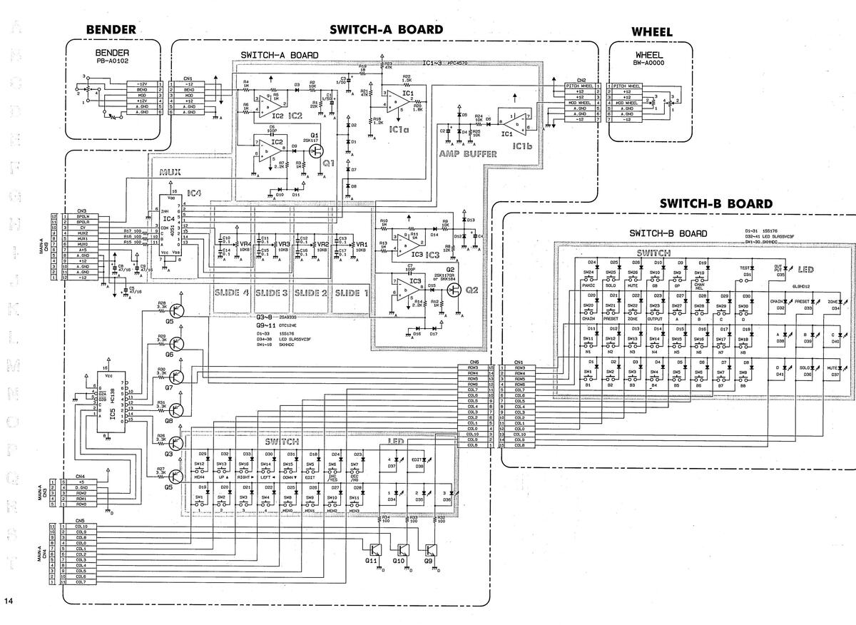
SWITCH-B BOARD
ASSY 7620412000
(pcb 22925658)
D1~31 1SS176 D32~41 LED SLR55VC3F ___SW1~30_SKHHDC____
031 --0 0---
SW30
D32
GL9HD12
D33
¥,A B ¥,A
D39
D ¥ 14 SOLO ¥ 14 MUTĖ ¥ 14 D41 D36 D37

View from foil side

View from foil side
N
1 2 3 4 5 6 7 8 9 10 11 12 13 14 15 16 17 18 19 20 21 22 23 24 25 26 27 28 29 30

View from foil side

(pcb 22925657 2/3)

View from foil side
JACK-B BOARD

JACK-A BOARD


IC DATA


CHANGE INFORMATION 変更案内
| • Soft | war | re re | evä | isi | on | |
|---|---|---|---|---|---|---|
| ROM | A | (IC | 2 | on | MAIN-A | Board) |
| MB27 | C-1 | 28-2 | 20 | (1 | 51797991 | F0) |
● ROMバージョンアップ ROM A (IC 2 on MAIN-A Board) MB27C-128-20 (15179799F0)
| 実施製番 | Ver.NO. | DESCRIPTION | 改良点 |
|---|---|---|---|
| Z 950000 | 1.01 | Ver 1.01 cures the following bugs. | 以下の症状が改善されました。 |
|
-
Z960 6 99 |
1.FC1 to FC4 are reversed to match
rear panel silk screen. |
1.FC1 から FC4 のジャックへの割当をリ
ヤパネルに合うように配列した. |
|
| 2970700 | 1.02 | Ver 1.02 cures the following bugs. | 以下の症状が改善されました。 |
| Z 981849 |
1.A-50's Benders adding LSB overflow
fixed. |
1. ベンダー及びホイールからのピッチ・ベ
ンド値あるいはモジュレーション値の加算 結果,オーバーフロー値を越えた場合はオ ーバーフロー値に固定する.症状としては ベンダーあるいはホイールのいずれかが最 大であり,同時に他方を動かした結果,最 大値に満たない値を出力することがあった が,これを改善した. |
|
| none | 1.03 | Ver 1.03 cures the following bugs. | 以下の症状が改善されました。 |
|
1.Musickeyboard Software routine
changed to correctly handle multiple key-On(s) (without key- Off(s))when the keyboard is dropped. |
|
||
| Z991850 | 1.04 | Ver 1.04 cures the following bugs. | ■以下の症状が改善されました。 |
| ир |
1.Add step detection to Foot con-
troller preprosessor. So that when using Foot switches as damper etc,only 00 7F 00 7F data is output.i.e.fixes stuck notes caused by hold pedal and MC-500. |
1. フット・コントローラーの処理プログラ
ムにステップ検知処理を追加した。 その結果、フットスイッチをダンパー 等に使用する際、00 7F 00 7F のデータ のみを出力するようになった。それ故、 ホールド・ペダルとMC-500によって 引き起こされるスタック・ノート(音が残 る)が改善された。 |
|
| 2.Fix lowest key bug in 1.03. |
2. Ver 1.03 における最低音鍵盤のキーナ
ンバーの間違いが直された。 |
NOTE: It is no problem that version number of ROM A is different from that of ROM B because of no relation between the ROMs. It is recommended that both ROMs are renewed to the latest version ones respectively.
注) ROM A と ROM Bの組み合せは、 どのバージョンでも可能です。 しかしROMの交換の際には両方共 それぞれ最新バージョンのROMに交換 することが望まれます。

|
ROM B (10
M5M27C256) |
C 3 on MAIN-B Board)
K-15(15179789BO) |
ROM B (IC 3 on MAIN-B Board)
M5M27C256K-15(15179789B0) |
|
|---|---|---|---|
| 実施製番 | Ver.NO. | DESCRIPTION | 改良点 |
| 2960200 | 1.01 | Ver 1.01 cures the following bugs. | 以下の症状が改善されました。 |
| Z960699 |
1.Bug in inc/dec editing in Program
Change receive channel fixed. |
1. Utility 内の MIDI Option のメニュー
において、Program Change のレシーブ チャンネルの設定を inc/dec ボタンで エディットする際、"none" の設定に戻る ことが出来なかった。 |
|
|
2.A-50 Patch Change set to be
ignored from front panel switches during Chain Play. |
2. Chain Play 中においては、フロントパ
ネルのスイッチ操作によるA-50のパッ チチェンジ情報無視されるように改善さま た。 |
||
| none | 1.02 | Ver 1.02 cures the following bugs. | 以下の症状が改善されました。 |
|
1. When setting Zone MIDI Channel,
and other Zones are set to 16 and 1,brink Slider movement result in random channels. |
1. Zone MIDI Channel を書き換える際、作
の Zone の Channel が、16 と 1 に設定 されているとスライダー3を用いた設定が うまく行かないことがあった。 |
||
|
2.CPU-B Version number displayed on
Test Mode. |
2.Test Mode において、ROM-B のバージョ
ンナンバーが確認できるようになった。 |
||
| none | 1.03 | Ver 1.03 cures the following bugs. | 以下の症状が改善されました。 |
|
1.Stop Aftertouch parameter edit
while key on. |
|
||
|
2.Fix active sensing from disappear-
ing ,if Active Sensing ON. |
|
||
|
3.Send Bender O when –
changing MIDI channel changing Bender ON/OFF. Send Modulation O when changing MIDI channel. |
|
||
| 4.Stop entering edit if Damper ON. |
4. ダンパー〇Nの状態ではエディット出来
ないようになった。 |
||
|
5.Fix Song Select so it doesn't do
running status. |
5. Song Select の出力がランニング・スラ
ータスにならないようにした。 |
||
| Z970700 | 1.04 | Ver 1.04 cures the following bugs. | 以下の症状が改善されました。 |
| 2971499 |
1.Fix Modulation so that scaling of
modulation for each Zone is inde- pendant of the modulation scaling set in any other Zone. |
1. ホイール及びベンダーのモジュレーション値は, ゾーン毎に独立に設定出来るよう
になった. |
| M5M27C256 | K-15(15179789B0) | M5MZ7CZ56K-15(15179789B0) | |||
|---|---|---|---|---|---|
| 実施製番 | Ver.NO. | DESCRIPTION | 改良点 | ||
| none | 1.05 | Ver 1.05 cures the following bugs. | 以下の症状が改善されました。 | ||
|
1.Make the Zone SOLOed also the Zone
selected in display if Edit ON. |
|
||||
|
2.Clear LCD after initializing it at
power ON.Put up "Zzzzzzzzzz" Wait message. |
2.電源投入時の初期化の後、LCDディス
プレイをクリアし、"Zzzzzzzzz"という ウエイト・メッセージを表示する。 |
||||
|
3.When Zone SOLOed or Unmuted,all
sliders,switches and foot control- ler are resent. |
|
||||
| 2981500 | 1.06 | Ver 1.06 cures the following bugs. | 以下の症状が改善されました。 | ||
| Z 9 9 1 9 |
1.Pedals and switches operate while
Edit ON. |
|
|||
| 2.Conroller editting disabbled while damper ON. |
|
||||
| Z A O 2 O | 1.07 | Ver 1.07 cures the following bugs. | 以下の症状が改善されました。 | ||
| up | - |
1.Fix corruption of negative trans-
pose value when saving and loading |
1. セーブおよびロード時の負のトランスポ
ーズ値の誤りが解消された。 |
||
|
2.Solo and Mute of Zones and Outputs
changed so that thier states are only written to the Patch memory if they are Solo/Mute with Edit ON . If Edit is OFF,Output/Zone Solo/ Mute will only be temporary. The state edited into the Patch will be recalled if the Patch is re- selected. |
|
||||
| E: | 注) | ||||
|
en convert
lues becom convert t ven in the )7 has a c convert P |
ing to CP
e incorred o the form original onvert rou atch Data |
U-B Ver 1.07,the transpose
ct. mat used by Ver 1.07,and System Exclusive spec,Ver utine. to Ver 1.07 format. |
ROM-B を Ver1.07 に交換すると、それまて
トランスポーズ値は誤った値になってしまい Ver1.07 によるフォーマットの変換を行い 本来の System Exclusive のスペックを与え に、Ver1.07 ではある変換ルーチンを備えて パッチのデータを Ver1.07 のフォーマット するには、以下の操作を行ってください。 |
||
|
l.Copy Pat
2.Change R 3.Reload R 4.Turn off 5.Insert a JACK. 3.With ped |
ches to a
om to Ver am Card da A-50 powe pedal DP al deprese |
Ram Card.
1.07. ata. er. -2 into PATCH SHIFT UP sed.turn on power. |
|
||
| Patch's | transepose | e values will be converted | 以上で、全てのパッチのトランスポーズの | ||
ROM B (IC 3 on MAIN-B Board)
ROM B (IC 3 on MAIN-B Board)
|
Changing the
(R10,R12,I) |
value of resisters
R14,R16 on the JACK-A Board) |
●抵抗値の修正 (JACK-Aボード; R10,R12,R14,R16) | ||
|---|---|---|---|---|
|
R10,R12,R14,R16
EFF.SN |
3 :100kΩ to 6.8kΩ
:ZA02000-up |
R10,R12,R14,R16
実施製番 |
:100kΩ to 6.8kΩ
:ZAO2000 より |
|
| Reason |
: To increase foot switch ON speed
by reducing the time constant of switch bounce hum filter. This Change was made with upgrate to ROM-A (Ver 1.04) Software. This Software detects the presence of foot switches with only ON OFF status, and this only sends data values of 00 and 7F. This was done to remove incompati- bility with MIDI equipment that does not respond to such MIDI data as "Continous Damper" |
理由 |
|
|
20


 Loading...