

Page 1
A-37
Sept, 2001
1
SERVICE NOTES
Issued by RES
First edition
Copyright © 2001 by ROLAND CORPORATION
All rights reserved. No parts of this publication may be reproduced in any form whithout the written permission of ROLAND CORPORATION.
SILKSCR. BOTTOM CABINET ASSY REMOVAL SCREW x10 Pcs
SELF TAP. SCREW 3,5x16 TCTCPRBZ Cod. J2289131
SN00053 K6018448 Printed in Italy (I00) (AD)
a-37
midi keyboard
controller
TABLE OF CONTENTS Page
SPECIFICATIONS 1
LOCATION OF CONTROLS 2
EXPLODED VIEW 3
KEYBOARD PARTS LIST 4
PARTS LIST 5
HOW TO VISUALIZE THE SYSTEM PROGRAM VERSION 6
HOW TO CARRY OUT THE FACTORY SETUP 6
HOW TO ENTER TEST MODE 6
BLOCK DIAGRAM 9
JACK PCB ASSY & CIRCUIT DIAGRAM 10
CPU PCB ASSY 10
CIRCUIT DIAGRAM (CPU PCB ASSY) 11
POWER SUPPLY PCB ASSY & CIRCUIT DIAGRAM 12
LEFT CONTROL PCB ASSY 12
CIRCUIT DIAGRAM (LEFT CONTROL PCB ASSY) 13
RIGHT CONTROL PCB ASSY & CIRCUIT DIAGRAM 14
RIGHT & LEFT CONTACT PCB ASSY & CIRCUIT DIAGRAM 15
Specifications
Keyboard: 76 keys, velocity sensitive, with channel Aftertouch
Display: 3 x 7 segments
Realtime controllers: Data Entry slider, Bender/Modulation lever, channel Aftertouch, Hold Foot Switch socket, Foot Pedal socket
Memories: 128 Patches
Connections: MIDI In, Out A, Out B, Thru, Expression Pedal, Sustain Footswitch, DC IN (adaptor)
Compatibility: GM/GM2/GS, all MIDI messages
Power supply : Batteries, AC/DC adaptor (DC 9V)
Dimension: 1195 (W) x 270 (D) x 113 (H) mm
Weight:: 7,7 Kg
Supplied accessories: 6 x dry batteries (AA type), MIDI cable, Owner’s Manual, Music Rest
Options: Roland ACA adaptor (9V, 200mA); DP-2, DP-6, or BOSS FS-5U footswitch; EV-5, Boss FV-300L expression pedal
Specifications subject to change without prior notice. All other trademarks mentioned in this manual are the property of the respective companies.
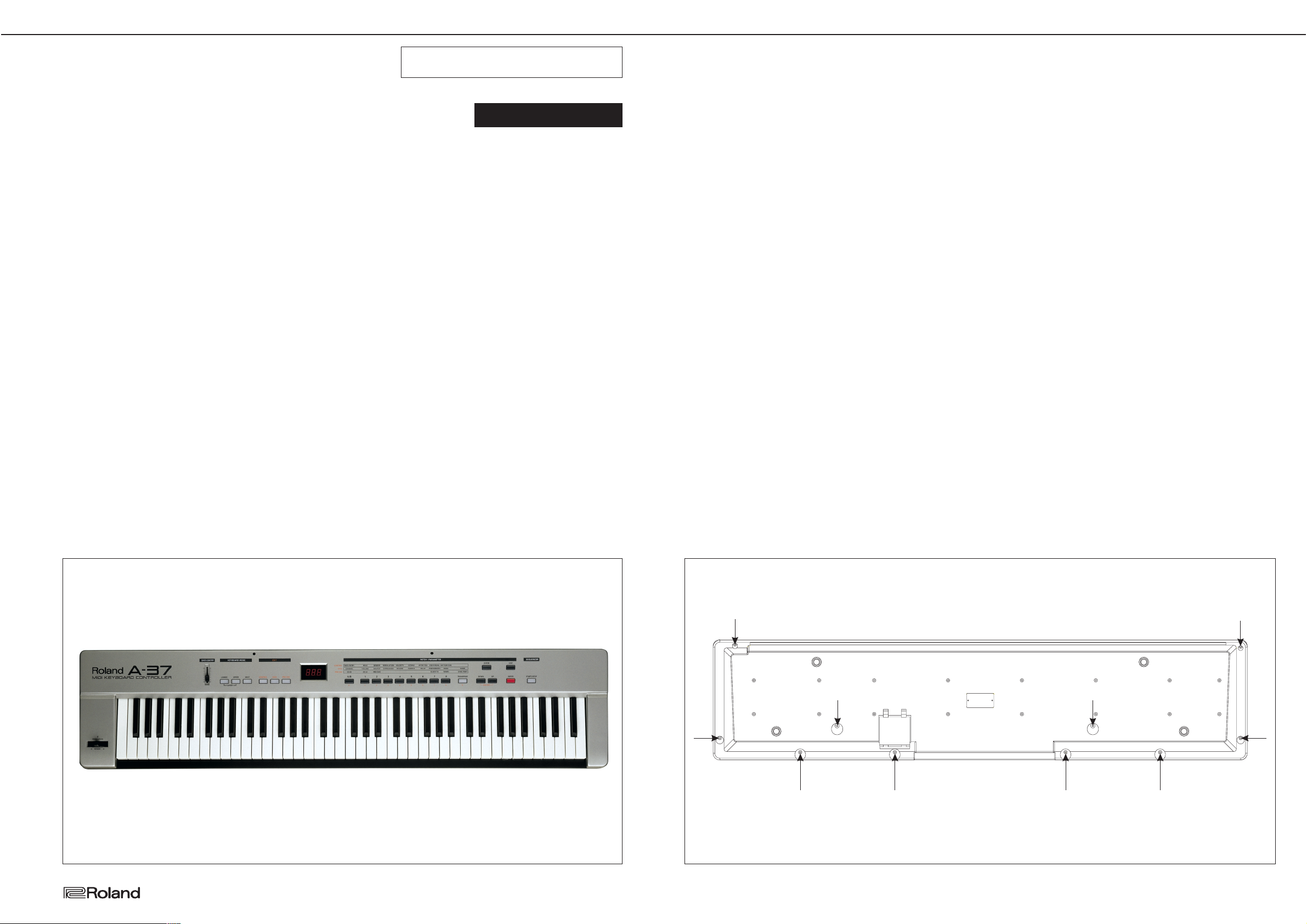
DISASSEMBLY
Page 2
2
A-37
Sept, 2001
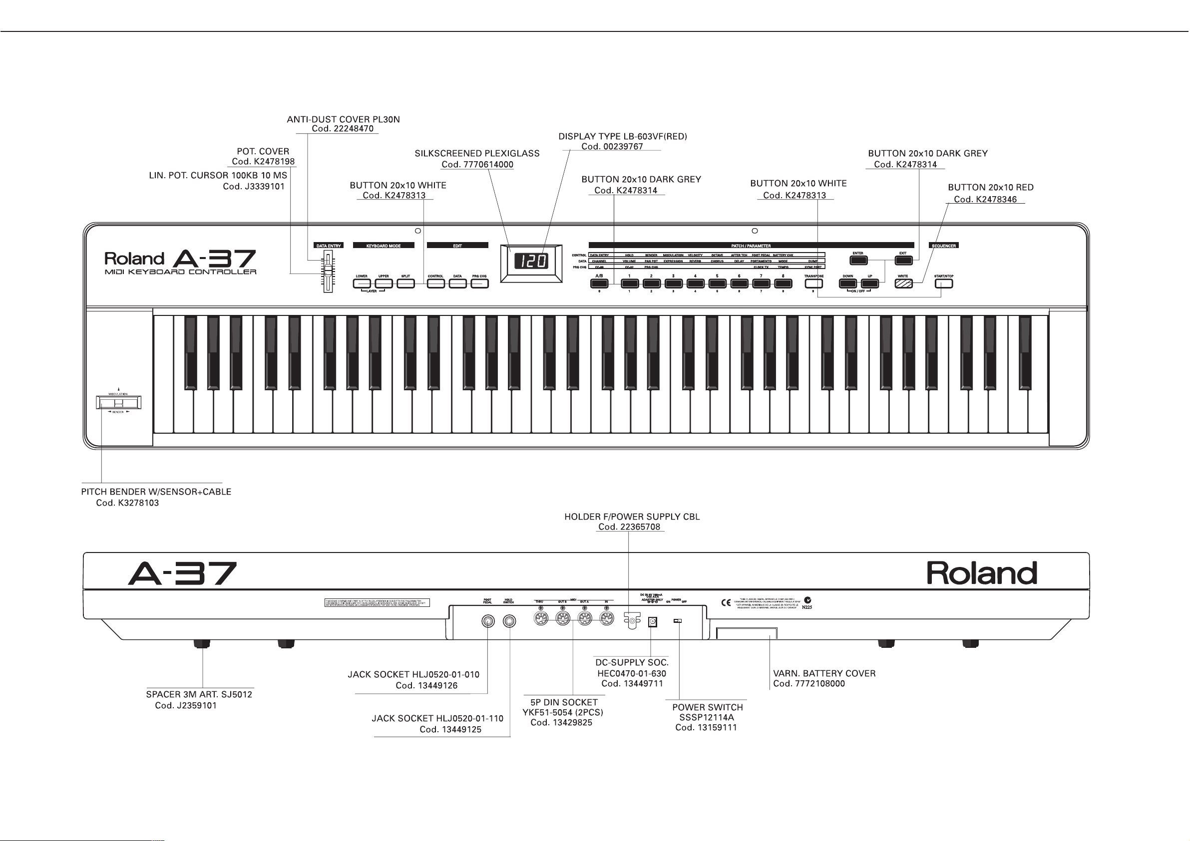
LOCATION OF CONTROLS
REAR VIEW
Page 3
3
A-37
Sept, 2001
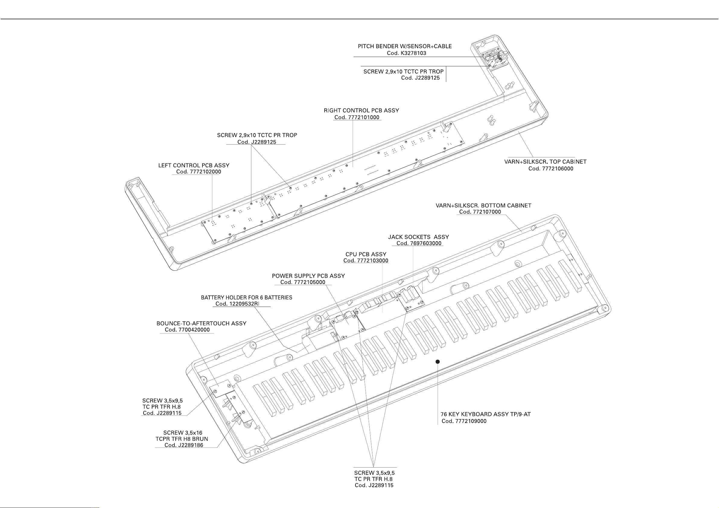
EXPLODED VIEW
Page 4
4
A-37
Sept, 2001
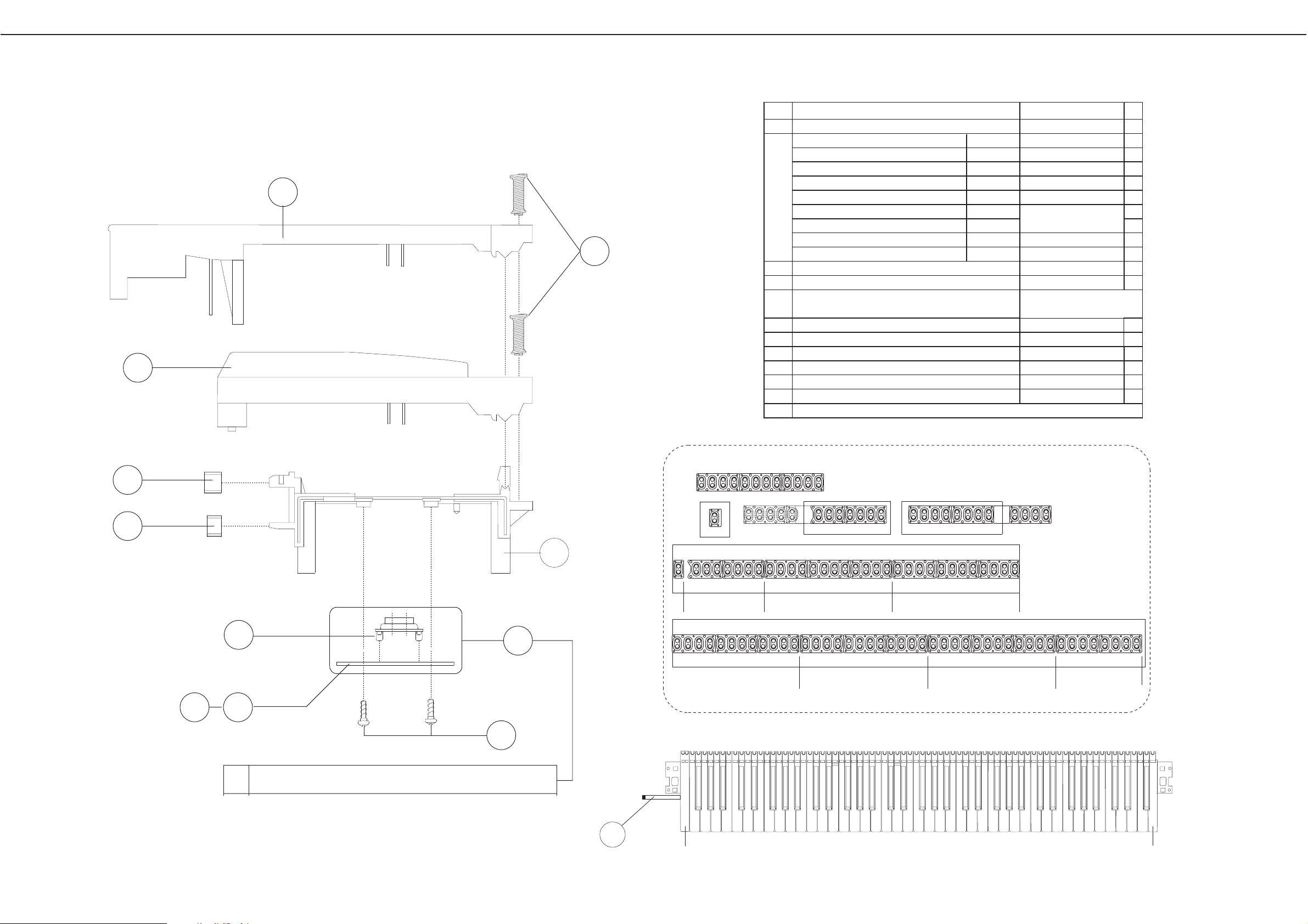
KEYBOARD PARTS LIST
76 KEY KEYBOARD TP/9-AT Code: 7772109000
1
2
3
8
10
9
PMSM
5
76
4
*
CONTACT BOARDS ARE COMPLETE WITH RUBBER CONTACTS
*
Ref
1
2
3
4
5
6
7
8
9
10
11
*
PARTS NAME
KEY SPRING gr.63
NATURAL KEY C5 (gr.10) DO
RE
MI
FA
SOL
LA
SI
MI(I)
SOL(F)
NATURAL KEY D6 (gr.10)
NATURAL KEY E7 (gr.10)
NATURAL KEY F1 (gr.10)
NATURAL KEY G2 (gr.10)
NATURAL KEY A3 (gr.10)
NATURAL KEY B4 (gr.10)
NATURAL KEY C8 (gr.10)
NATURAL KEY G (gr.10)
MATT SHARP KEY (gr.10)
SELF TAP SCREW 2.9x8 TCTCPRBZ
12P RUBBER CONTACT
1P CONDUCTIVE RUBBER LR13/1
LEFT CONTACT BOARD W/RUBBER ASSY
RIGHT CONTACT BOARD W/RUBBER ASSY
PLASTIC CHASSIS
GUIDE BUSHING INFERIOR
GUIDE BUSHING SUPERIOR
CONTACT BOARDS ARE COMPLETE WITH RUBBER CONTACTS
SOL (F)
MI (I)
76KEY TP/9-ATKEYBOARD ASSY
PARTS NUMBER
n.
J2179101 76
6
6
6
7
6
6
6
1
1
31
42
7**
1
1
1
1
1
76
76
J2579112
J2579113
J2579114
J2579115
J2579116
J2579117
J2579118
J2579119
J2579121
J2579120
J2289126
2218523802
7625920000
7695005000
7695004000
J2589101
J2359104
22158789
11
LEFT
RIGHT
AB C
CCCD
C
12 P RUBBER CONTACT
D
C
** CUT AND ASSEMBLY OF RUBBER CONTACTS
B
A
SENSOR AFTER TOUCH
J3169112
Page 5
A-37
Sept, 2001
5
CASING Q.ty
K2198102 MUSIC REST 1
22208320 MUSIC SCORE HOLDER 1
# 7772106000 VARN+SILKSCR. TOP CABINET A-37 1
# 7772107000 VARN+SILKSCR. BOTTOM CABINET A-37 1
# 7772108000 VARN. BATTERY COVER A-37 1
7770614000 SILKSCREENED PLEXIGLASS RD-150 1
KNOB BUTTON
K2478198 POT. COVER 1
K2478313 BUTTON 20X10 WHITE 8
K2478314 BUTTON 20X10 DARK GREY 13
# K2478346 BUTTON 20X10 (RED) 1
SWITCH
J3169105 SWITCH EVQ-PAE 05 R SW1,2,3,4,5,6,7 on CPU / SW1 => 15 on LCB 22
13159111 POWER SWITCH S SSP12114A SW1 on PS 1
JACK, SOCKET
13449125 JACK SOCKET HLJ0520-01-110 JK1 on JB 1
13449126 JACK SOCKET HLJ0520-01-010 JK4 on JB 1
13429825 5P DIN SOCKET YKF51-5054 (2PCS) JK1,2 on CPU 2
13449711 DC-SUPPLY SOC. HEC0470-01-630 JK3 on PS 1
DISPLAY UNIT
00239767 DISPLAY TYPE LB-603VF (RED) DS1 on LCB 1
KEYBOARD ASSY
# 7772109000 76 KEY KEYBOARD ASSY TP/9-AT 1
NOTE: For details, refer to KEYBOARD PARTS LIST (Page 4)
PCB ASSY
# 7772105000 POWER SUPPLY PCB ASSY A-37 1
7697603000 JACK SOCKETS ASSY A-33 1
7700420000 BOUNCE-TO-AFTERTOUCH ASSY 1
# 7772101000 RIGHT CONTROL PCB ASSY A-37 1
# 7772102000 LEFT CONTROL PCB ASSY A-37 1
# 7772103000 CPU PCB ASSY A-37 1
7695004000 RIGHT CONTACT BOARD W/RUBBER ASSY 1
7695005000 LEFT CONTACT BOARD W/RUBBER ASSY 1
IC
15229718RI I.C. 6N 137 PHOTO-COUPLER IC1 on CPU 1
15169550RI I.C. 74 HC138 DIP CMOS IC2 on LCB 1
15249111 I.C. TC7WU04 F FLAT CMOS IC13 on CPU 1
15259821 I.C. TC74HC573AF IC9 on CPU 1
00129278 I.C. SSC1080 FOB (CUSTOM IC) IC10 on CPU 1
# J5259153 I.C. AT24C64N-10SC 64K EPROM IC5 on CPU 1
15259884 I.C. TC7S08F MOS CMOS IC8 on CPU 1
15249104 I.C. TC7S04F FLAT IC11 on CPU 1
J5259149 I.C. TC74VHC541FT FLAT IC6 on CPU 1
15219183 I.C. M51953 AL (STANDING) IC7 on CPU 1
15149146 IC TD62583AP (INTERF.DRIVER IC) IC3 on LCB 1
15289141 I.C. M5223FP-600D IC12 on CPU 1
# 7772104000 I.C. MICRO CONTR.IC2 CPU (PROGRAM.) A-37 IC2 on CPU 1
TRANSISTOR
15319101 TRANSISTOR 2SC-2412K Q5 on CPU 1
15329503 TRANSISTOR DTA-124 EK CHIP Q1,2,3 on CPU 3
15329516 TRANSISTOR DTC-114EK Q4 on CPU 1
15119163 TRANSISTOR RN2227 Q1,2,3,4 on LCB 4
J5119105 TRANSISTOR TN6717A Q3 on PS 1
DIODE
15019159RI DIODE 1N-4148 On LCB / on RCB / on RC/ on LC 158
15339108 DIODE DA-204K D1,2,3 on CPU 3
J5029112 LED DIODE 5 L-53 SRD-D / RED D1 =>12 on LCB / D1,2,3,4 on RCB 16
15019345RI ZENER DIODE BZX79C 5.6V D5 on PS 1
J5019105 DIODE 1N 4002 D1 on PS 1
RESISTOR
J3919104 RESISTOR ARRAY EXB-A10E-103-J RA1,3,4,5,6 on CPU 5
J3919108 RESISTOR ARRAY EXB-V8V-103-JV RA2 on CPU 1
J3809129 UNINFL. RES. 220 OHM 0.6W 5% R1,2,3,4,5,6,7,8 on LCB 8
POTENTIOMETER
J3339101 LIN. POT. CURSOR 100KB 10 MS VR1 on LCB 1
CAPACITOR
J3629103 ELECTRL.COND. 100U 25V P5 C1 on PS 1
J3629104 ELECTRL.COND. 10U 50V P5 C21,22 on PS 2
J3629105 ELECTRL.COND. 47U 50V P5 C2 on PS 1
J5369103 ELECTR. COND. RV2 100U 16V (SMD) C30 on CPU 1
J5369104 ELECTR. COND. RV2 10U 16V (SMD) C2,11,16,23 on CPU 4
J5369102 ELECTR.COND. RV2 47U 16V SMD C3,5,65 on CPU 3
J5369106 ELECTR. COND. RV2 1U 50V (SMD) C20,33,64 on CPU 3
J3629150 ELECTR.COND. 47U 16V H.7 C3,2 on LCB 2
INDUCTOR, COIL, FILTER
<<EMI>> 12449382RI NOISE SUP. PLT1-R53C FL1 on PS 1
<<EMI>> 12449370 NOISE SUP. SBT-0160W L1,2,3,4 on CPU / L7,9 on JB 6
<<EMI>> 12449326 NOISE SUP. SBT-0460 L5 on CPU 1
CRYSTAL, RESONATOR
00894034 X-TAL 16 MHZ MA-406 X1 on CPU 1
01124812 QUARTZ 10 MHZ MA-406 X2 on CPU 1
CONNECTOR
13419677RI 16P FEM. CONNECTOR AMP 1.27 CN4,2 on CPU / on LC 3
13369689RI 20P FEM. CONNECTOR AMP 1.27 CN6 on CPU / on RC 2
J3429122 14P FEM. CONNECTOR AMP 1.27 CN1 on RCB / CN3 on CPU 2
13439479RI MALE CONN.AMP 6W STANDING CN1 on JB / CN8 on CPU 2
J3439123 6P MALE CONN. P. 2 M 90° CN4 on LCB 1
J3429120 3P MALE CONNECTOR P.2 M CN10 on CPU / CN401 on AFT 2
J3439168 4P MALE CONNECTOR 76384-404 CN402 on AFT 1
WIRING, CABLE
7695108001 16P FLAT CABLE (24) -2C From CN4 on CPU to LC 1
7700112000 3P CABLE ASSY (64) -2C P.2 From CN10 on CPU to CN401 on AFT 1
BATTERY
J2569102 2-BATTERY SET 'AA'-SIZE (ALK.) 3
SCREW
J2289122 SCREW 2.2X6 TC TC BRUN 2
J2289125 SCREW 2.9X10 TC TC PR TROP 32
J2289131 SELF TAP.SCREW 3.5X16 TCTCPRBZ 26
J2289118 SCREW 2.9X16 TC TC PR BRUN 5
J2289115 SCREW 3.5X9.5 TC PR TFR H.8 14
J2289186 SCREW 3.5X16 TCPR TFR H.8 BRUN 4
PACKING
# K2638260 RIGHT POLYST. END-SIDE A-37 1
# K2638261 LEFT POLYST. END-SIDE A-37 1
K2678109 CARTENE ENVELOPE HD 150X40 1
K2678106 POLYETH.ENVELOPE 4OX55 1
# K2618257 OUTER PACKING A-37 1
MISCELLANEOUS
K2168117 LED SPACER H.1,5 D.E.5,5 16
J2359101 SPACER 3M ART. SJ5012 4
22248470 ANTI-DUST COVER PL30N 1
13419723RI 9V BATTERY CONNECTION 1
12209532RI BATTERY HOLDER FOR 6 BATTERIES 1
22365708 HOLDER F/POWER SUPPLY CBL 1
13429823RI P. SUPPLY PLUG LOCKING 1
ACCESSORIES
23485228 MIDI CABLE 1M - BLACK 1
K6018109 MIDI GUIDE 1
# K6018447 OWNER'S MANUAL (E/D/F/SP/IT/OL) A-37 1
PARTS LIST A-37
When ordering any parts listed in the parts list,please specify the following items in the order sheet.
QTY PART NUMBER DESCRIPTION MODEL NUMBER
Ex. 10 22575241 Sharp Key C-20/50
15 2247017300 Knob (orange) DAC-15D
Failure to completely fill the above items with correct number and description will result in delayed or
even undelivered replacement.
CONSIDERATION ON PARTS ORDERING
NOTE:
# The parts marked " # '' are new (Initial Parts).
A The parts marked " A '' are new (Initial Parts).for RES but already used by RJA
The parts marked have Safety - Related characteristics.
Use only listed parts for replacement.
<< EMI >> Component for EMC.
NNoo ttee :: Replacement should be made on a unit basis. No replacements available for individual parts.
Replacement only be a unit.
SAFETY PRECAUTIONS :
The parts marked have
safety-related characteristics.
Use only listed parts for
replacement.
RCB = Right Control Board
LCB = Left Control Board
CPU = CPU Board
PS = Power Supply B.
JB = Jack Board
AFT = Bounce After Touch Board
!
!
!
Page 6

A-37
Sept, 2001
6
a) Front Panel check (Controls)
Once you have entered the control panel check, press button 1:
The display visualizes:
If you press the button 1, you check the b
uttons.
If you press the button 2, you check the LEDs
.
If you press the button 3, you check the Controls (modulation, bender, data entry).
Buttons check
Once you have entered the front panel test mode, press button 1.
The display visualizes pict. A:
If you press the buttons of the control panel one after the other, the display will visualize their name.
When you release the button, the display will visualize: OFF (See pict. B).
Press EXIT and WRITE at the same time to exit.
The test procedure automatically goes back to the previous menu.
Note: It is not possible to go on to the following step if this test is not carried out correctly.
If you exit the test before checking all the buttons, the display indicates the name of the untested
buttons.
Press EXIT to go back to the main menu.
LED c
heck
Once you have entered the control panel check, press button 2.
The control panel LEDs and the display segments will light in sequence.
Press EXIT to leave this test.
Press EXIT again to go back to the main menu.
Contr
ol check (modulation, bender, data entry)
Once you have entered the control panel check, press button 3.
The display visualizes:
Pressing the button 1, you check the MODULA
TION (bender lever).
Pressing the button 2, you check the BENDER
.
Pressing the button 3, you check the DATA ENTRY potentiometer.
MODULA
TION
Once you have pressed the button 1, the display visualizes:
Pict. A (value 0) if the bender lever is released;
Pict. B (value 127) if the bender lever is moved completely forward.
A B
A B
TEST MODE
ITEMS REQUIRED:
· MIDI cable;
· Dumper Pedal;
· Expression Pedal EV-5;
· Digital multimeter.
HOW TO VISUALIZE THE SYSTEM PROGRAM VERSION
Turn the instrument on, while keeping pressed the button 2 of section PATCH.
After a few seconds, the display will visualize a writing identifying the software version:
i.e.: VER 100 - 26 jul 2001
To exit, turn the instrument off.
HOW TO CARRY OUT THE FACTORY SETUP
Turn the instrument on while keeping the button WRITE pressed.
After a few seconds, the display will visualize the writing Factory setup.
The Factory Setup function re-establishes the instrument's factory settings.
HOW TO ENTER TEST MODE
Turn the instrument on while keeping pressed the button 1 of section PATCH.
After a few seconds, the display will visualize the following writing:
TEST ROLAND A - 37 VERSION 1.00
Then the display visualizes:
Every button of section Patch corresponds to a test to carry out.
Button 1 ⇒ P
anel check ("F": Front, "R": Rear);
Button 2 ⇒ K
eyboard check
Button 3 ⇒ Memory check
Turn the instrument off to exit test mode.
Note: After carrying out the tests, the instrument automatically performs the Factory Setup.
1) PANEL CHECK (FRONT / REAR)
Once entered test mode, press button 1. The display visualizes:
If you press button 1, you check the Front Control Panel (a).
If you press button 2, you check the sockets placed on the Rear panel.
Press EXIT to come back to the previous menu.
Page 7

A-37
Sept, 2001
7
Press EXIT to leave.
Press EXIT again to go back to the main menu.
BENDER
Once you have pressed the button 2, the display visualizes:
Pict. A (value 0) if the bender is in central position;
Pict. B (value 63) if the bender lever is moved completely rightwards;
Pict. C (value - 63) if the bender lever is moved completely leftwards.
Press EXIT to leave.
Press EXIT again to go back to the main menu.
D
ATA ENTRY
Once you have pressed button 3, the display visualizes:
Pict. A (value 0) if the potentiometer slider is in low position;
Pict. B (value 127) if the potentiometer slider is in high position.
Press EXIT to leave.
Press EXIT again to go back to the main menu.
b)
Rear Panel check (Socket)
Once you have entered the rear panel test mode rear panel, press button 2.
The display visualizes:
Press button 1, to check DUMPER and EXPRESSION
pedals.
Press button 2, to check the P
ower battery.
Press button 3, to check the MIDI.
DUMPER and EXPRESSION pedals check
Once you have entered the rear panel test mode, press button 1.
The display visualizes:
Press button 1, to check the DUMPER pedal.
Press button 2, to check the EXPRESSION pedal.
DUMPER PEDAL
Insert the Dumper Pedal into the HOLD SWITCH socket.
Once you have entered the pedals test mode, press button 1.
A B
A B C
If you press the pedal, the display visualzes the status (ON) of the pedal (Pict. A); when you release
the pedal, the display visualizes its new status (OFF) (Pict. B).
Press EXIT to leave.
Press EXIT again to go back to the main menu.
EXPRESSION PEDAL
Insert the Expression Pedal into the FOOT PEDAL socket.
Once you have entered the pedals test mode, press button 2.
Before pressing the button, the display visualizes 0 (Pict. A). If you press the pedal to all its stroke,
the display visualizes 127 (Pict. B).
Press EXIT to leave.
Press EXIT again to go back to the main menu.
P
ower Battery check
Once you have entered the rear panel test mode, press button 2.
The display visualizes a value representing the power battery charge level, expressed in % value
(i.e.: 100 = 100 %).
Press EXIT to leave.
Press EXIT again to go back to the main menu.
Midi c
heck
Once you have entered in the rear panel test mode, press button 3.
The display visualizes:
Press button 1. The display visualizes:
Connect MIDI IN and MIDI OUT A sockets by a Midi cable.
In case of correct data transmission and reception, the display visualizes the writing "go".
In case of failure, the display visualizes "A - I".
Press EXIT to leave.
Press EXIT again to go back to the main menu.
Press button 2. The display visualizes:
A B
A B
Page 8

8
A-37
Sept, 2001
Note: When carring out this test, make sure you press the key properly.
In case a key does not reack 127, try pressing a few other keys.
In any case, a tolerance 08-10% is acceptable.
Press EXIT to leave.
Press EXIT again to go back to the main menu.
3) MEMORY CHECK
Once you have entered in test mode, press button 3.
The display visualizes:
The instrument carries out the DEVICE CHECK (Pict. A) automatically.
Caution: Don't turn the power off during this test. If the power goes off accidentally, carry out the test again.
At the end of all the tests, make sure the display visualizes the writing "go" (Pict. B). This means that the
instrument memory has been implemented correctly. In case the display visualizes the writing "Err", it means
that the memory is damaged.
Press EXIT to leave.
To exit, turn the power off.
Note 1: When you turn the power on again, the Factory Setup is carried out automatically.
Note 2: If you press EXIT when the display visualizes the main menu, you enter test mode again.
A B
Connect MIDI IN and MIDI OUT B sockets by a Midi cable.
In case of correct data transmission and reception, the display visualizes the writing "go".
In case of failure, the display visualizes "b - I".
Press EXIT to leave.
Press EXIT again to go back to the main menu.
2) KEYBOARD CHECK
Once you have entered test mode, press the button 2:
The display visualizes:
Press button 1, the display visualizes:
Connect one of the Midi outputs (OUT A or OUT B) to the Midi in of another musical instrument or of a dedicated equipment, provided of a sound source.
Press the keyboard keys. When the keys are released, the display visualizes OFF.
When you press a key, you hear a Piano sound and the display visualizes the velocity level (from 0 to 127).
Press EXIT to leave.
Press EXIT again to go back to the main menu.
AFTER
TOUCH CHECK
Once you have entered the keyboard test, press button 2.
The display visualizes:
Press the keyboard keys. When the keys are released, the display visualizes 0.
If you press the key, the display viasualizes the level of the After Touch function, according to the
pressure put on the key.
Released Key
Key pressed at max pressure
Released key
Pressed key
Page 9

A
B
C
D
E
F
G
H
I
L
M
N
O
P
Q
R
S
T
U
J
K
12345678910 12131415161718192021222324252627282930
9
11
A-37
Sept, 2001
BLOCK DIAGRAM
PHOTO
CPU
RESET
X1
X2
KEYSCAN
DATA
LED
MATRIX
BUFFER
SWITCH
MATRIX
JACK BOARD
CPU BOARD
CONTROL BOARD
10MHz
IC10
XINT
A0
A1
XRD
XWR
XCS
16MHz
XIN
XOUTXOUT
RXD3
XRES
BEND-MOD
AN0-AN2
AN4
AN5AN5
P32
P33
P36
D0-D7
P00-P07
MK0-MK9
T0-T7
P10-P13
P20-P27
P50-P52
TXD3
TXD1
IN
OUT2
OUT1
THRU
SUSTAIN
SWITCH
EXPRESSION
PEDAL
INT1
P30
P31
POWER SUPPLY
DC IN 9V
POWER SWITCH
BATTERY
+
-
POWER SUPPLY BOARD
VBTY +5VD
BR0-BR9
UNIT
ENTRY
76 KEY
KEYBOARD
AN3
IC12
EEROM
IC5
AFT
WP
SCK
SDA
P56
P55
P57
BUFFERDECODER
DISPLAY
CLK
IC6
IC9
IC2
M38039FFFP
IC7
IC1
BUFFER
IC3
IC2
Q1-Q4
LATCH
3STATE
3
1
2
3
1
2
1
4
2
5
3
1
4
2
5
3
1
4
2
5
3
1
4
2
5
3
1
2
3
1 2
1 2
Page 10

A
B
C
D
E
F
G
H
I
L
M
N
O
P
Q
R
S
T
U
J
K
12345678910 12131415161718192021222324252627282930
10
11
A-37
Sept, 2001
CPU PCB ASSY
ASSY 7772103000
View from component side
SUSTAIN
SWITCH
EXPRESSION
PEDAL
EXPJ
VRL
From CPU Board
SUST
DGND
DGND
VRH
(CN5)
VRH
VRH
JK4
HLJ_0520_01_010
3
2
1
L9
SBT0160W
1
2
4
3
JK1
HLJ_0520_01_110
3
1
2
R26
1K8
R27
470K
L7
SBT0160W
1
2
4
3
CN1
6 WIRE CABLE P2.5
3
4
2
1
5
6
JACK PCB ASSY & CIRCUIT DIAGRAM
ASSY 7697603000
View from component side
Page 11

A
B
C
D
E
F
G
H
I
L
M
N
O
P
Q
R
S
T
U
J
K
12345678910 12131415161718192021222324252627282930
11
11
A-37
Sept, 2001
CIRCUIT DIAGRAM (CPU PCB ASSY)
IN
OUT1
OUT2
A37 KEYB
LEFT
RIGHT
HOLD
FOOTPED
THRU
TO
JACK
BOARD
FOR BUILT-IN FLASH
PROGRAMMING
FROM
POWER
SUPPLY
TEST
MODSEL0
MODSEL1
TO
AFTER
TOUCH
TO LEFT CONTROL BOARD
TO LEFT CONTROL BOARD
(CN2)
(CN3)
LLD6
LLD1
LLD2
LLD4
LLD3
LLD0
LLD5
BEND
HOLD
DBEAM
BTYCHK
KD0
KD5
KD2
KD3
KD3
KD5
KD4
INT
KD4
KD6
KD7
KD1
KD0
KD7
KD2
KD6
KD1
INT
D0
D0
D6
KD7
D6
KD6
D7
D2
D4
D3
D0
D7
D3
D1
D5
D5
KD3
D7
KD5
D6
D2
D4
D6
D1
D2
D0
D5
D5
D2
D4
D3
D1
KD0
D1
KD4
D7
D4
D3
KD1
KD2
XRD
OUT2
IN
IN
XINT
XINT
XWR
OUT2
XRD
XCS
XINT
XRD
XCS
XWR
XWR
RES
BR10
MK8
BR9
MK9
MK10
A0
A1
A0
A1
MK10
MK10
MK6
MK6
BR0
BR4
BR4
T3
T4
BR9
T6
T4
MK2
BR5
T0
BR4
MK5
MK6
MK0
T5
BR0
T4
BR1
MK1
MK7
BR10
MK6
BR3
MK3
MK9
MK3
MK0
MK2
BR1
BR0
BR4
MK1
BR4
T0
T6
T7
MK3
T0
MK4
BR2
MK2
MK2
BR0
MK10
MK8
BR3
BR0
BR7 T7
T0
T2
BR7
MK4
MK4
T1
MK9
MK1
BR6
MK3
BR6 T5
T4
T4
T3
BR2
T0
BR2
T1
MK3
BR6
MK0
BR5
MK5
MK1
BR1
MK8
T1
BR10
T7
MK7
BR3
MK7
T1
T1
BR3
BR10
MK9
MK6
T3
T2
T6
T2
T6
BR9
MK7
BR1
MK1
BR1
T5
MK0
T7
T3
MK0
MK5
MK10
BR10
BR2
BR6
MK4
BR7
T7
T2
BR3
T5
BR9
T2
MK5
BR5
BR5
BR2
BR6
MK4
MK5
BR7
BR7
MK8
T6
MK9
T5
MK7
MK2
BR5
MK8
BR9
T3
HOLD
OUT1
OUT1
RES
FSCLK
FVPP
FBUSY
FVPP
FXOE
FBUSY
FRES
FRES
A0
A1
XCS
XRD
XWR
XINT
RSVD
FSCLK
FXOE
FSDA
FSDA
BTYCHK
LLD0
LLD2
LLD4
LLD1
LLD3
LLD5
LLD7
MOD
WP
SCK
SDA
SDA
SCK
WP
SCK
SPD SPD
DIVEN
DIVEN
BEND
MOD
DATA
DATA
AFT
RSVD
LLD7
BR8
BR8
BR8
BR8
BR8
WP
SCK
SDA
SC3
SSC3
MOD
DATA
BEND
SSD0
SSD3
SSD3
SSD3
SSD1
SSD2
SSD1
SSD2
SSD0
SSD1
SSD0
SSD2
SSC2
SC2
LLD6
SSC3
SSC2 SC2
SC3
SSC1
SC1
SSC0 SSC1
SC0
SC0SSC0
SC1
XRES
XRES
XRES
XRES
SDA
DBEAM
FOOTPED
FOOTPED
AFT
+5VD
+5VD
+5VD
+5VD
+5VD
+5VD
+5VD
+5VD
+5VD
+5VD
+5VD
+5VD
VBTY+5VD
+5VD
+5VD
VBTY
+5VD
+5VD
+5VD
+5VD
+5VD
+5VD
REF
REF
REF
REF
REF
REF
REF
+5VD
+5VD
+5VD
+5VD
+5VD
D
D
D
D
D
D
D
D
D
D
D
D
D
D
D
D
D
D
D
D
D
D
D
D
D
D
D
D
D
D
D
D
D
D
D
D
D D
D
D
D
D
D D
D
D
D
REF
5VREF
5VREF
5VREF
5VREF
5VREF
REF
REF
REF
VBTY
D
R45
270s
IC5
STMM24 C64_MN6
8
7
1
2
3
5
6
4
VCCWPA0
A1
A2
SDA
SCL
GND
IC10
SSC1080
7
33
20
46
24
23
22
21
19
18
17
16
15
14
13
12
11
10
9
8
6
5
4
3
2
1
31
30
29
28
27
26
25
32
49
48
47
44
43
42
41
40
39
38
37
34
36
35
45
50
51
52
VDD
VDD
VSS
VSS
SC10
PR10
SC9
PR9
SC8
PR8
SC7
PR7
SC6
PR6
SC5
PR5
SC4
PR4
SC3
PR3
SC2
PR2
SC1
PR1
SC0
PR0
T7
T6
T5
T4
T3
T2
T1
T0
CLK
A1
A0
D7
D6
D5
D4
D3
D2
D1
D0
INT
RD
WR
CS
RESET
TEST1
TEST2
R20
22Ks
X2
MA_406_10M000Hz
R21
10Ks
R40
10Ks
C48
27pFs
C58
22pFs
C59
22pFs
C28
100nFs
RA1
8x10Ks
4
5
6
7
8
9
3
2
1
C51
27pFs
SW1
NIU
R36
0s
C29
100nFs
C64
1uF16s
C15
100nFs
D1
DA204K
21
3
IC1
6N137
1
2
3
4 5
6
7
8
NC
LA
LC
NC GND
OUT
EN
VCC
C53
27pFs
C23
10uF16s
R34
0s
R22
0s
CN4
AMPC1_2716P
3
4
5
6
7
8
2
1
9
10
11
12
13
14
15
16
CN6
AMPC1_2720P
3
4
5
6
7
8
2
1
9
20
19
18
17
16
15
14
13
12
1110
R42
1Ks
C33
1uF16s
C36
27pFs
C55
27pFs
CN10
53014_0 310
3
2
1
L5
SBT0460
C12
100nFs
C66
100nFs
R3 3K3s
Q5
2SC2412K
2
1
3
C57
27pFs
C49
100nFs
R25
1Ks
IC6
TC74VHC541FT
2
3
4
5
6
7
8
9
1
19
18
17
16
15
14
13
12
11
2010
A1
A2
A3
A4
A5
A6
A7
A8
G1
G2
Y1
Y2
Y3
Y4
Y5
Y6
Y7
Y8
VCCGND
IC9
TC74HC573AF
2
3
4
5
6
7
8
9
11
1
19
18
17
16
15
14
13
12
2010
D1
D2
D3
D4
D5
D6
D7
D8
C
OC
Q1
Q2
Q3
Q4
Q5
Q6
Q7
Q8
VCCGND
C35
27pFs
C61
27pFs
R38
0s
C42
100nFs
C1
100nFs
IC8
TC7S08F
1
2
4
53
R43
0s
RA3
8x10Ks
4
5
6
7
8
9
3
2
1
RA6
8x10Ks
4
5
6
7
8
9
3
2
1
RA4
8x10Ks
4
5
6
7
8
9
3
2
1
CN7
NIU
3
4
5
6
7
8
2
1
9
20
19
18
17
16
15
14
13
12
1110
CN9
NIU
3
4
5
6
7
8
2
1
9
20
19
18
17
16
15
14
13
12
1110
R15
10Ks
R16
NIU
IC4
NIU
8
7
1
2
3
5
6
4
VCCWPA0
A1
A2
SDA
SCL
GND
Q3
DTA124EK
2
13
C8
27pFs
C32
NIU
C47
100pFs
C14
100nFs
JK1
YKF515054
2
1
3
4
5
6
JK2
YKF515054
2
1
3
4
5
6
L1
SBT0160W
1
2
4
3
TP
TP6
C17
100nFs
TP
TP5
C18
100nFs
L2
SBT0160W
1
2
4
3
C31
100nFs
C27
220nF
Poly 5%
C24
NIU
CN8
6 WIRE CABLE P2.5
3
4
2
1
5
6
L3
SBT0160W
1
2
4
3
R30
NIU
R23
10Ks
L4
SBT0160W
1
2
4
3
CN1
C_1_27_2510_6002_UN
3 4
5 6
21
7 8
9 10
C2
10uF16s
C20
1uF16s
C19
100nFs
C62
10nFs
TP
TP1
C3
47uF16s
R33
NIU
C52
27pFs
R46
100s
R26
0s
R27
0s
C65
47uF16s
C16
10uF16s
R2 220s
Q1
DTA124EK
2
13
R5 220s
R4 220s
C10
100nFs
IC12A
M5223FP
2
3
1
IC12B
M5223FP
6
5
7
R12 220s
R11 220s
C54
27pFs
R17 220s
R13 220s
RA5
8x10Ks
4
5
6
7
8
9
3
2
1
IC12C
M5223FP
84
CN2
AMPC1_2716P
3
4
5
6
7
8
2
1
9
10
11
12
13
14
15
16
C11
10uF16s
R6 0s
C56
27pFs
C37
27pFs
C6
27pFs
R7 0s
R18 NI U
R19 1Ks
C21
10nFs
R9 0s
R10 0s
C7
27pFs
C5
47uF16s
Q2
DTA124EK
2
13
R29
56Ks
C9
27pFs
R24
10Ks
C60
27pFs
C39
27pFs
X1
MA_406_16M000Hz
R32
47Ks
C25
22pFs
C26
22pFs
D2
DA204K
21
3
D3
DA204K
2 1
3
C38
27pFs
IC2
M38039FFFP
48
47
46
45
44
43
42
41
40
39
38
37
36
35
34
33
21
20
17
16
15
25
26
27
28
29
30
31
32
57
24
18
59
58
52
54
53
55
56
23
22
19
51
50
49
14
13
12
4
5
6
7
8
9
10
11
60
61
62
63
64
1
2
3
P00/AN8
P01/AN9
P02/AN10
P03/AN11
P04/AN12
P05/AN13
P06/AN14
P07/AN15
P10/INT41
P11/INT01
P12
P13
P14
P15
P16
P17
P40/INT40/XCOUT
P41/INT00/XCIN
P42/INT1
P43/INT2
P44/RXD1
P27/LED7
P26/LED6
P25/LED5
P24/LED4
P23/LED3
P22/LED2
P21/LED1
P20/LED0
VCC
VSS
CNVSS/VPP
AVSS
VREF
P34/RXD3
P32
P33
P31/DA2
P30/DA1
XOUT
XIN
XRES
P35/TXD3
P36/SCLK3
P37/XSRDY3
P45/TXD1
P46/SCLK1
P47/XSRDY1/CNTR2
P57/INT3
P56/PWM
P55/CONTR1
P54/CONTR0
P53/XSRDY2
P52/SCLK2
P51/SOUT2
P50/SIN2
P67/AN7
P66/AN6
P65/AN5
P64/AN4
P63/AN3
P62/AN2
P61/AN1
P60/AN0
C41
27pFs
Q4
DTC114EK
2
1
3
IC3
NIU
1
2
4
53
CN5
6 WIRE CABLE P2.5
3
4
2
1
5
6
C4
10nFs
IC7
M51953A
2
3
5
4
1
NC
GND
RES
CAP
VCC
R1
22Ks
R28
10Ks
C40
27pFs
C30
100uF16s
R8
22Ks
C63
100nFs
C44
27pFs
TP
TP4
C43
27pFs
C13
100nFs
TP
TP3
RA2
4x10Ks
12
4
6
8
3
5
7
C46
27pFs
R41
10Ks
CN3
AMPC1_2714P
3
4
5
6
7
2
1
8
9
10
11
12
13
14
R14
10Ks
C45
27pFs
IC11
TC7S04F
2 4
53
C22
100nFs
IC13C
TC7WU04F
6 2
IC13B
TC7WU04F
3 5
R44
1Ms
TP
TP2
IC13A
TC7WU04F
1 7
IC13D
TC7WU04F
84
C34
100nFs
C50
27pFs
Page 12

A
B
C
D
E
F
G
H
I
L
M
N
O
P
Q
R
S
T
U
J
K
12345678910 12131415161718192021222324252627282930
12
11
A-37
Sept, 2001
POWER SUPPLY PCB ASSY & CIRCUIT DIAGRAM
ASSY 7772105000
LEFT CONTROL PCB ASSY ASSY 7772102000
View from component side
View from component side
-
DC IN 9V
+
-
BATTERY
To CPU Board
(MN1500 6 pcs)
+
(CN8)
P
P
VCCVBT
VBT
VCC
Q3
TN6717A
2
13
SW1
SSSP12114A
1 2
C15
100nFC
C14
100nFC
FL1
PLT1R53C
1
2
4
3
CN4
CONN_2X1
2
1
R24
270
C2
47uF16
C1
100uF16
D1
1N4001
1 2
D5
BZX79C5V6
1 2
C21
10uF16
CN3
6 WIRE CABLE P2.5
3
4
2
1
5
6
JK3
HEC047001630
1
2
3
C22
10uF16
Page 13

A
B
C
D
E
F
G
H
I
L
M
N
O
P
Q
R
S
T
U
J
K
12345678910 12131415161718192021222324252627282930
13
11
A-37
Sept, 2001
FROM CPU BOARD
FROM CPU BOARD
TO RIGHT CONTROL BOARD
YEL
RED
ORG
BRW N
GRN
BLEU
TO MOD-BENDER UNIT
LOWER UPPER SPLIT CONTROL
DATA PROGRAM A/B 1
2345
876
CHANGE
LOWER
UPPER
SPLIT
CONTROL
DATA
PROGRAM
CHANGE
DISPLAY 3X7 SEGMENTS
CL0
CL1
CL2
CL3
(CN2)
(CN3)
(CN1)
ALL LEDS ARE:
EVQPAE05R
5L53SRDD_RED
ALL SWITCHES ARE:
SSD0
SSD1
SSD2
SSD3
MOD
BEND
DATA
SSD1
SSD0
LLD0
LLD2
LLD4
LLD6
LLD1
LLD3
LLD5
LLD7
RW1
RW2
RW3
RW4
RW5
RW7
RW6
LLD0
LLD1
LLD2
LLD3
LLD4
LLD5
LLD6
LLD7
DATA
MOD
RW5
RW6
RW7
RW2
DRW0
DRW0
RW1
RW3
RW0
DRW0
RW4
DRW0
RW0
SSD2
SSD3
BEND
DRW5
DRW2
DRW5
DRW1
DRW1
DRW2
DRW3
DRW4
DRW5
DRW2
DRW3
DRW3
DRW3DRW5
DRW1
DRW1
DRW4
DRW2
DRW4
DRW4
YY3
DRW7
DRW7
DRW6
DRW7
DRW6
DRW6
DRW7
DRW6
DRW6
CL3
DRW7
CL3 SSD3
SSD1
SSD0
SSD2
YY3
Y1
Y3
SC0 Y0
Y4
SC1
SC1
Y5
Y4
Y2
Y2
Y2SC2
Y3
Y5
Y3
SC3
Y0
Y1
Y0
SC2
SC0
Y1
SC3
D
REF
5VREF +5VD
D
D
+5VD
D
D
REF
5VREF
REF
5VREF
5VREF
D
D
+5VD
D16
12
D15
12
CN1
14 WIRE CABLE P1.27
3
4
5
6
7
2
1
8
9
10
11
12
13
14
D1
12
R1
220I
IC2
74HC138P
1
2
3
6
4
5
15
14
13
12
11
10
9
7
16
8
A
B
C
G1
G2A
G2B
Y0
Y1
Y2
Y3
Y4
Y5
Y6
Y7
VCC
GND
D2
12
DS1
LB603VF
7
6
4
2
1
9
10
38
5
11
12
13
14
15
16
17
18
19
20
21
22
23
24
25
26
27
28
d2
e2
c1
d1
e1
DP2
e3
A1ac2
DP1
d3
g3
c3
DP3
b3
a3
f3
A3
A2
b2
a2
g2
f2
b1
a1
A1b
f1
g1
D5
12
D6
12
D9
12
D10
12
Q1
RN2227
3
1
2
C1
100nF
R2
220I
R4
220I
R3
220I
D3
12
D4
12
D8
12
R6
220I
R5
220I
Q4
RN2227
3
1
2
Q3
RN2227
3
1
2
Q2
RN2227
3
1
2
D11
12
D7
12
D12
12
R8
220I
R7
220I
C5
100nF
C4
100nF
CN4
53015_0 610
3
4
2
1
5
6
VR1
POT. SLIDER 100KB 10MS
13
2
SW13
SW9
SW5
SW1 SW2
SW14
SW10
SW6
CN2
3
4
5
6
7
8
2
1
9
10
11
12
13
14
15
16
SW11
SW7
SW3
SW12
SW8
SW15
SW4
C3
47uF16
C2
47uF16
R10
10K
IC3
TD62583AP
109
8
7
6
5
4
3
2
1
11
12
13
14
15
16
17
18
NCGND
I7
I6
I5
I4
I3
I2
I1
I0
O7
O6
O5
O4
O3
O2
O1
O0
R9
NIU
CN3
3
4
5
6
7
2
1
8
9
10
11
12
13
14
D13
12
D14
12
CIRCUIT DIAGRAM (LEFT CONTROL PCB ASSY)
Page 14

A
B
C
D
E
F
G
H
I
L
M
N
O
P
Q
R
S
T
U
J
K
12345678910 12131415161718192021222324252627282930
14
11
A-37
Sept, 2001
RIGHT CONTROL PCB ASSY & CIRCUIT DIAGRAM ASSY 7772101000
View from component side
TRANSPOSE
ENTER
DOWN UP
EXIT
WRITE
START/STOP
TRANSPOSE
START/STOP
FROM LEFT CONTROL BOARD
(CN1)
SSD3
SSD2
SSD1
SSD1
SSD2
SSD3
DRW7
YY3
CL3
DRW6
SSD0
YY3
SSD0
Y5
Y5
DRW6
CL3
DRW7
Y4
Y4
D
CN1
AMPC1_2714P
3
4
5
6
7
2
1
8
9
10
11
12
13
14
D6
12
D2
12
D1
12
D4
12
D3
12
SW1
SW5
SW3
SW6
SW4
SW7
SW2
D5
12
Page 15

A
B
C
D
E
F
G
H
I
L
M
N
O
P
Q
R
S
T
U
J
K
12345678910 12131415161718192021222324252627282930
15
11
A-37
Sept, 2001
LEFT CONTACT PCB ASSY w/RUBBER ASSY 7695005000
CIRCUIT DIAGRAM (LEFT CONT.PCB ASSY)
CIRCUIT DIAGRAM (RIGHT CONT.PCB ASSY)
RIGHT CONTACT PCB ASSY w/RUBBER
ASSY 7695004000
View from component side
View from component side
 Loading...