

Page 1
Page 2
Contents of the Package
201a
Before using this unit, carefully read the sections entitled: “USING THE UNIT
SAFELY” and “IMPORTANT NOTES” (p. 3; p. 5). These sections provide important
information concerning the proper operation of the unit. Additionally, in order to
feel assured that you have gained a good grasp of every feature provided by your
new unit, Owner’s manual should be read in its entirety. The manual should be
saved and kept on hand as a convenient reference.
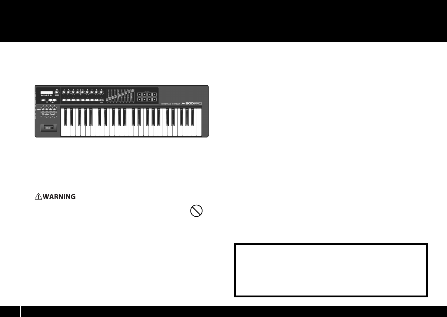
The package of the A-300PRO/500PRO/800PRO (which we’ll subsequently refer to as the A-PRO) contains the following items. When you open the package, first make sure that all items are
included. If any are missing, contact the dealer where you purchased the A-PRO.
MIDI keyboard controller A-PRO
fig
* The photo show the A-500PRO.
A-PRO CD-ROM
This contains the A-PRO drivers.
* Avoid touching or scratching the shiny underside (encoded surface) of the disc.
Damaged or dirty discs may not be read properly. Keep your discs clean using a
commercially available CD cleaner.
Do not attempt to play back a CD-ROM or DVD-ROM in a conventional
audio CD player. The resulting sound may be of a level that could cause
permanent hearing loss. Damage to speakers or other system components
may result.
USB cable
Use this cable to connect the A-PRO to the USB connector of your computer. For details
on connections, refer to “Installing the Driver” (p. 12).
* Please use only the included USB cable. If y ou require a replacement for the supplied
USB cable (for example due to damage or loss), please contact the nearest Roland
Service Center, or an authorized Roland distributor, as listed on the separate sheet
titled “Information.”
Owner’s manual
This is the document you’re reading. Keep it at hand for reference when needed.
Ableton Live Lite Serial Number Card
The Ableton Live Lite serial number card contains a serial number that you will need
when you install Ableton Live Lite. This serial number cannot be reissued. Please take
care not to lose it.
For details on the installation procedure and other information, refer to http://
roland.cm/livelite. Please be aware that Roland does not provide support for Ableton
Live Lite.
202
Copyright © 2010 ROLAND CORPORATION
All rights reserved. No part of this publication may be reproduced in any form
without the written permission of ROLAND CORPORATION.
Roland and GS are either registered trademarks or trademarks of Roland
Corporation in the United States and/or other countries.
2
Page 3
USING THE UNIT SAFELY
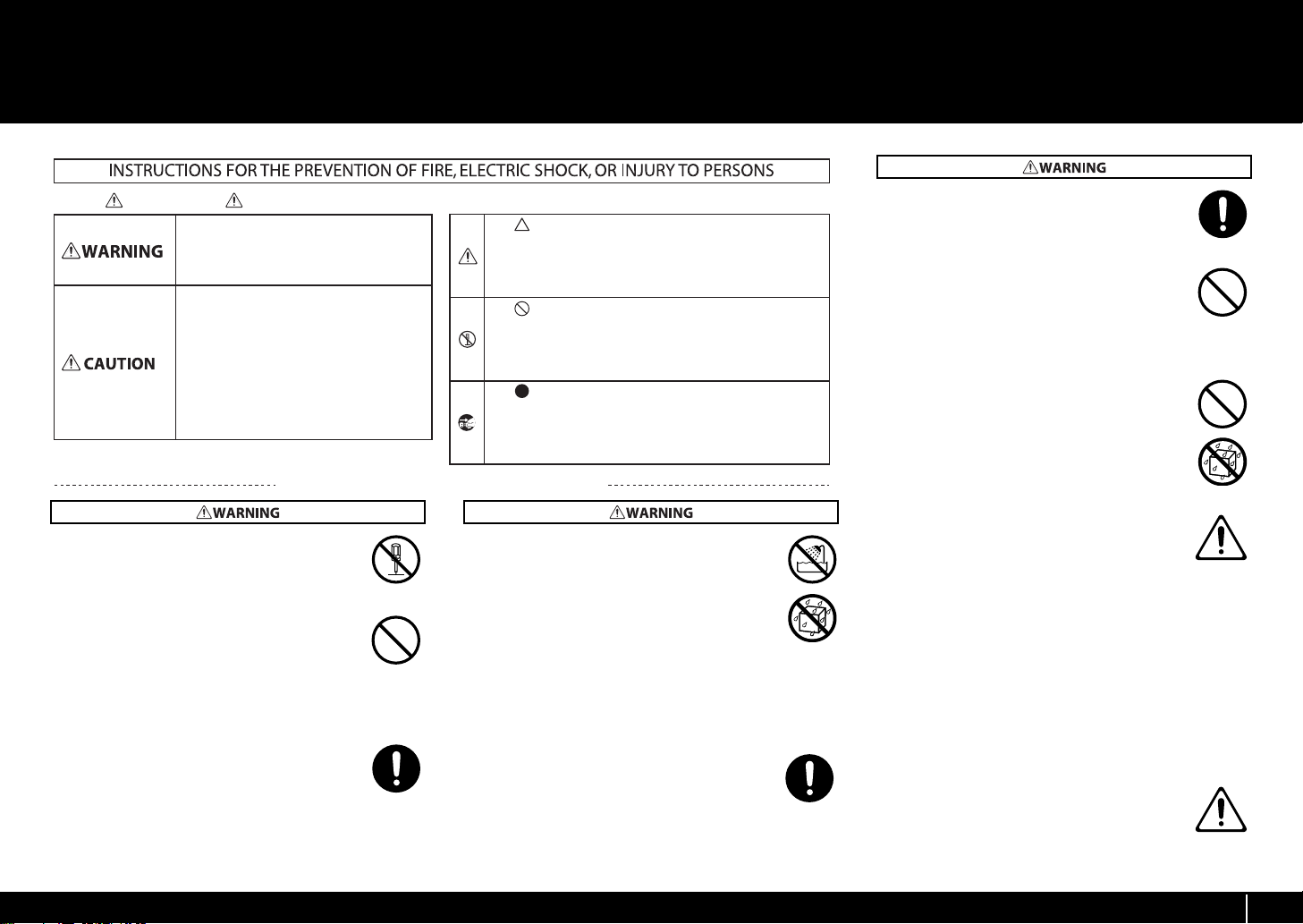
About WARNING and CAUTION Notices
Used for instructions intended to alert the
user to the risk of injury or material
damage should the unit be used
improperly.
* Material damage refers to damage or
other adverse eects caused with
respect to the home and all its
furnishings, as well to domestic animals
or pets.
Used for instructions intended to alert the
user to the risk of death or severe injury
should the unit be used improperly.
The symbol alerts the user to things that must be
carried out. The specic thing that must be done is
indicated by the design contained within the circle. In the
case of the symbol at left, it means that the power-cord
plug must be unplugged from the outlet.
The symbol alerts the user to important instructions or
warnings.The specic meaning of the symbol is
determined by the design contained within the triangle. In
the case of the symbol at left, it is used for general
cautions, warnings, or alerts to danger.
The symbol alerts the user to items that must never be
carried out (are forbidden). The specic thing that must
not be done is indicated by the design contained within
the circle. In the case of the symbol at left, it means that
the unit must never be disassembled.
About the Symbols
ALWAYS OBSERVE THE FOLLOWING
002c
• Do not open (or modify in any way) the unit or its
AC adaptor.
..............................................................................................................
003
• Do not attempt to repair the unit, or replace parts
within it (except when this manual provides specific
instructions directing you to do so). Refer all
servicing to your retailer, the nearest Roland Service
Center, or an authorized Roland distributor, as
listed on the separate sheet titled “Information.”
..............................................................................................................
007
• Make sure you always have the unit placed so it is
level and sure to remain stable. Never place it on
stands that could wobble, or on inclined surfaces.
..............................................................................................................
004
• Never install the unit in any of the following locations.
• Subject to temperature extremes (e.g., direct
sunlight in an enclosed vehicle, near a heating
duct, on top of heat-generating equipment); or are
• Damp (e.g., baths, washrooms, on wet floors); or are
• Exposed to steam or smoke; or are
• Subject to salt exposure; or are
•Humid; or are
• Exposed to rain; or are
• Dusty or sandy; or are
• Subject to high levels of vibration and shakiness.
..............................................................................................................
008b
• Use only the specified AC adaptor (sold separately),
and make sure the line voltage at the installation
matches the input voltage specified on the AC
adaptor’s body. Other AC adaptors may use a
different polarity, or be designed for a different voltage, so their
use could result in damage, malfunction, or electric shock.
..............................................................................................................
008e
• Use only the attached power-supply cord. Also,
the supplied power cord must not be used with
any other device.
..............................................................................................................
009
• Do not excessively twist or bend the power cord,
nor place heavy objects on it. Doing so can
damage the cord, producing severed elements
and short circuits. Damaged cords are fire and
shock hazards!
..............................................................................................................
011
• Do not allow any objects (e.g., flammable material,
coins, pins); or liquids of any kind (water, soft
drinks, etc.) to penetrate the unit.
..............................................................................................................
012b
• Immediately turn the power off, remove the AC
adaptor from the outlet, and request servicing by
your retailer, the nearest Roland Service Center, or
an authorized Roland distributor, as listed on the
separate sheet titled “Information” when:
• The AC adaptor, the power-supply cord, or the
plug has been damaged; or
• If smoke or unusual odor occurs
• Objects have fallen into, or liquid has been
spilled onto the unit; or
• The unit has been exposed to rain (or otherwise
has become wet); or
• The unit does not appear to operate normally or
exhibits a marked change in performance.
..............................................................................................................
013
• In households with small children, an adult should
provide supervision until the child is capable of
following all the rules essential for the safe
operation of the unit.
..............................................................................................................
3
Page 4
USING THE UNIT SAFELY
012d
• Immediately turn the power off, and request
servicing by your retailer, the nearest Roland
Service Center, or an authorized Roland
distributor, as listed on the separate sheet titled
“Information” when:
• If smoke or unusual odor occurs
• Objects have fallen into, or liquid has been
spilled onto the unit; or
• The unit has been exposed to rain (or otherwise
has become wet); or
• The unit does not appear to operate normally or
exhibits a marked change in performance.
..............................................................................................................
014
• Protect the unit from strong impact.
(Do not drop it!)
..............................................................................................................
015
• Do not force the unit’s power-supply cord to share
an outlet with an unreasonable number of other
devices. Be especially careful when using
extension cords—the total power used by all
devices you have connected to the extension
cord’s outlet must never exceed the power rating
(watts/amperes) for the extension cord. Excessive
loads can cause the insulation on the cord to heat
up and eventually melt through.
..............................................................................................................
016
• Before using the unit in a foreign country, consult
with your retailer, the nearest Roland Service
Center, or an authorized Roland distributor, as
listed on the separate sheet titled “Information.”
..............................................................................................................
023
• Do not attempt to play back a CD-ROM or DVDROM in a conventional audio CD player. Damage
to speakers or other system components may
result.
..............................................................................................................
101b
• The unit and the AC adaptor should be located so
their location or position does not interfere with
their proper ventilation.
..............................................................................................................
102c
• Always grasp only the plug on the AC adaptor cord
when plugging into, or unplugging from, an outlet
or this unit.
..............................................................................................................
103b
• At regular intervals, you should unplug the AC
adaptor and clean it by using a dry cloth to wipe all
dust and other accumulations away from its
prongs. Also, disconnect the power plug from the
power outlet whenever the unit is to remain
unused for an extended period of time. Any
accumulation of dust between the power plug and
the power outlet can result in poor insulation and
lead to fire.
..............................................................................................................
104
• Try to prevent cords and cables from becoming
entangled. Also, all cords and cables should be
placed so they are out of the reach of children.
..............................................................................................................
106
• Never climb on top of, nor place heavy objects on
the unit.
..............................................................................................................
107c
• Never handle the AC adaptor or its plugs with wet
hands when plugging into, or unplugging from,
an outlet or this unit.
..............................................................................................................
108b
• Before moving the unit, disconnect the AC
adaptor and all cords coming from external
devices.
..............................................................................................................
108c
• Disconnect all cords coming from external
devices before moving the unit.
109b
• Before cleaning the unit, turn off the power and
unplug the AC adaptor from the outlet.
..............................................................................................................
110b
• Whenever you suspect the possibility of lightning
in your area, disconnect the AC adaptor from the
outlet.
..............................................................................................................
204
* Microsoft, Windows, and Windows Vista are registered
trademarks of Microsoft Corporation.
206e
* The screen shots in this document are used in compliance
with the guidelines of the Microsoft Corporation.
206j
* Windows® is known officially as: “Microsoft® Windows®
operating system.”
207+209
* Apple, Macintosh, and Mac OS are registered trademarks of
Apple Inc.
20
* All product names mentioned in this document are trademarks
or registered trademarks of their respective owners.
* MMP (Moore Microprocessor Portfolio) refers to a patent
portfolio concerned with microprocessor architecture, which
was developed by Technology Properties Limited (TPL). Roland
has licensed this technology from the TPL Group.
..............................................................................................................
4
Page 5

IMPORTANT NOTES
Power Supply
301
• Do not connect this unit to same electrical outlet that is being
used by an electrical appliance that is controlled by an
inverter (such as a refrigerator, washing machine, microwave
oven, or air conditioner), or that contains a motor. Depending
on the way in which the electrical appliance is used, power
supply noise may cause this unit to malfunction or may
produce audible noise. If it is not practical to use a separate
electrical outlet, connect a power supply noise filter between
this unit and the electrical outlet.
302
• The AC adaptor will begin to generate heat after long hours of
consecutive use. This is normal, and is not a cause for concern.
307
• Before connecting this unit to other devices, turn off the
power to all units. This will help prevent malfunctions and/or
damage to speakers or other devices.
Placement
352a
• This device may interfere with radio and television reception.
Do not use this device in the vicinity of such receivers.
352b
• Noise may be produced if wireless communications devices,
such as cell phones, are operated in the vicinity of this unit.
Such noise could occur when receiving or initiating a call, or
while conversing. Should you experience such problems, you
should relocate such wireless devices so they are at a greater
distance from this unit, or switch them off.
354a
• Do not expose the unit to direct sunlight, place it near devices
that radiate heat, leave it inside an enclosed vehicle, or
otherwise subject it to temperature extremes. Excessive heat
can deform or discolor the unit.
355b
• When moved from one location to another where the
temperature and/or humidity is very different, water droplets
(condensation) may form inside the unit. Damage or
malfunction may result if you attempt to use the unit in this
condition. Therefore, before using the unit, you must allow it
to stand for several hours, until the condensation has
completely evaporated.
358
• Do not allow objects to remain on top of the keyboard. This
can be the cause of malfunction, such as keys ceasing to
produce sound.
360
• Depending on the material and temperature of the surface on
which you place the unit, its rubber feet may discolor or mar
the surface.
You can place a piece of felt or cloth under the rubber feet to
prevent this from happening. If you do so, please make sure
that the unit will not slip or move accidentally.
Maintenance
401a
• For everyday cleaning wipe the unit with a soft, dry cloth or
one that has been slightly dampened with water. To remove
stubborn dirt, use a cloth impregnated with a mild, nonabrasive detergent. Afterwards, be sure to wipe the unit
thoroughly with a soft, dry cloth.
402
• Never use benzine, thinners, alcohol or solvents of any kind, to
avoid the possibility of discoloration and/or deformation.
Repairs and Data
452
• Please be aware that all data contained in the unit’s memory
may be lost when the unit is sent for repairs. Important data
should always be backed up in your computer, or written
down on paper (when possible). During repairs, due care is
taken to avoid the loss of data. However, in certain cases (such
as when circuitry related to memory itself is out of order), we
regret that it may not be possible to restore the data, and
Roland assumes no liability concerning such loss of data.
Additional Precautions
551
• Please be aware that the contents of memory can be
irretrievably lost as a result of a malfunction, or the improper
operation of the unit. To protect yourself against the risk of
losing important data, we recommend that you periodically
save a backup copy of important data you have stored in the
unit’s memory in your computer.
552
• Unfortunately, it may be impossible to restore the contents of
data that was stored in your computer once it has been lost.
Roland Corporation assumes no liability concerning such loss
of data.
553
• Use a reasonable amount of care when using the unit’s
buttons, sliders, or other controls; and when using its jacks
and connectors. Rough handling can lead to malfunctions.
554
• Never strike or apply strong pressure to the display.
556
• When connecting / disconnecting all cables, grasp the
connector itself—never pull on the cable. This way you will
avoid causing shorts, or damage to the cable’s internal
elements.
558b
• To avoid disturbing your neighbors, try to keep the unit’s
volume at reasonable levels (especially when it is late at
night).
559a
• When you need to transport the unit, package it in the box
(including padding) that it came in, if possible. Otherwise, you
will need to use equivalent packaging materials.
561
• Use only the specified expression pedal (EV-5 or EV-7; sold
separately). By connecting any other expression pedals, you
risk causing malfunction and/or damage to the unit.
CD-ROM and DVD-ROM handling
801
• Do not touch the data surface (the unprinted surface) of the
disc, or allow it to be scratched. Doing so may make the data
unreadable. If the disc gets dirty, clean it using a commercially
available disc cleaner.
5
Page 6

Contents
Contents of the Package................................................... 2
USING THE UNIT SAFELY................................................... 3
IMPORTANT NOTES........................................................... 5
Names of Things and What They Do................................ 8
Panel....................................................................................................................................................8
Side Panel ........................................................................................................................................11
Installing the Driver ........................................................12
Windows 8/Windows 7/Windows Vista Users....................................................................12
Windows XP Users........................................................................................................................15
Mac OS X Users ..............................................................................................................................17
Verifying that Installation was Successful............................................................................19
Checking with a SONAR Soft Synths (Windows)..............................................19
Checking in GarageBand (Mac OS X)....................................................................20
Look what You Can Do with the A-PRO .........................21
Play.....................................................................................................................................................21
Use ACT ............................................................................................................................................21
Use Control Maps..........................................................................................................................21
Create Your Own Settings .........................................................................................................21
Using A-PRO Editor ......................................................... 22
Installing A-PRO Editor................................................................................................................22
Windows Users .............................................................................................................22
Mac OS X Users .............................................................................................................22
MIDI Port Assignments ...............................................................................................................23
Windows Users .............................................................................................................23
Mac OS X Users .............................................................................................................23
Items in the Windows..................................................................................................................24
Main Window ................................................................................................................24
Message Assignment Window................................................................................24
Keyboard Set Window ...............................................................................................26
Menus ...............................................................................................................................................27
File Menu ........................................................................................................................27
Edit Menu .......................................................................................................................27
Options Menu ...............................................................................................................27
Help Menu......................................................................................................................27
Keyboard Shortcuts .....................................................................................................................28
Using Control Maps .....................................................................................................................29
Assigning MIDI Messages.........................................................................................29
Checking the Assigned MIDI Messages...............................................................30
Receiving a Control Map from the A-PRO ..........................................................31
Transmitting a Control Map to the A-PRO..........................................................31
Saving a Control Map on Your Computer............................................................................32
Loading a Control Map that was Saved on Your Computer .........................................32
Message Parameters...................................................................................................33
Using Keyboard Sets....................................................................................................................40
Receiving a Keyboard Set .........................................................................................40
Transmitting a Keyboard Set...................................................................................40
Performing (Play Mode) ................................................. 41
Playing the Keyboard..................................................................................................................41
Convenient Performance Functions......................................................................................41
Specifying the Current Channel (MIDI Transmit Channel).............................................42
MIDI Channel.................................................................................................................42
Selecting Sounds (PROGRAM CHANGE/BANK)..................................................................43
PROGRAM CHANGE ....................................................................................................43
Bank Select (BANK)......................................................................................................43
Selecting the UPPER and LOWER Sounds............................................................................44
Selecting the UPPER Sound.....................................................................................44
Selecting the LOWER Sound....................................................................................44
Layering Two Sounds (DUAL)...................................................................................................45
Playing Two Sounds Separately (SPLIT)................................................................................45
Adjusting the Playing Dynamics (VELOCITY)......................................................................46
Specifying a Fixed Velocity (KEY VELOCITY) ......................................................46
Changing the Keyboard Touch (VELOCITY CURVE) ........................................46
Muting the Controller Values (PRM MUTE)..........................................................................47
PRM MUTE......................................................................................................................47
6
Page 7

Contents
Assigning MIDI Messages (EDIT Mode) ......................... 48
Assigning a MIDI Message on the A-PRO Keyboard.........................................................48
Note Assignments.......................................................................................................49
Aftertouch Assignment .............................................................................................50
Control Change Assignment ...................................................................................51
Program Change Assignment.................................................................................52
RPN/NRPN Assignment .............................................................................................53
Tempo Assignment.....................................................................................................54
Convenient Functions.................................................................................................................56
Copying an Assignment............................................................................................56
Clearing an Assignment (NO ASSIGN)..................................................................56
System Settings (EDIT Mode) .........................................57
LCD Contrast Setting...................................................................................................................59
LCD CONTRAST.............................................................................................................59
Keyboard-related Settings.........................................................................................................60
KEYBOARD VELOCITY CURVE ..................................................................................60
KEYBOARD AFTERTOUCH CURVE...........................................................................61
KEYBOARD PORT SET..................................................................................................61
KEYBOARD ACTIVE PART...........................................................................................62
TRANSPOSE....................................................................................................................62
SHIFT KEY LATCH .........................................................................................................62
Pad-related Settings ....................................................................................................................63
PAD VELOCITY CURVE................................................................................................63
PAD AFTERTOUCH CURVE........................................................................................63
Clock-related Settings.................................................................................................................64
MIDI CLOCK ON/OFF...................................................................................................64
MIDI CLOCK DEFAULT TEMPO ................................................................................64
MIDI CLOCK OUTPUT PORT......................................................................................64
USB-related Settings....................................................................................................................65
ADVANCED DRIVER MODE.......................................................................................65
MIDI-related Settings...................................................................................................................66
MIDI I/F SWITCH ...........................................................................................................66
MIDI MERGE DESTINATION ......................................................................................67
Control Map Settings...................................................................................................................68
STARTUP MEMORY......................................................................................................68
[VALUE] knob Settings................................................................................................................68
FUNCTION ......................................................................................................................68
Other Settings................................................................................................................................69
H-ACTIVITY ON/OFF....................................................................................................69
L9 FUNCTION.................................................................................................................69
OMNI ................................................................................................................................70
FACTORY RESET............................................................................................................70
Making the Power Automatically Turn Off After a Time (AUTO OFF).......70
Appendices...................................................................... 71
Two MIDI Ports...............................................................................................................................71
Connecting the A-PRO Directly to a Sound Module ........................................................72
About Standard Driver Mode...................................................................................................73
Installing the Standard Driver.................................................................................73
Input/output Device Settings .................................................................................73
Troubleshooting ............................................................. 74
Problems when Installing the Driver.....................................................................................74
Problems with Settings...............................................................................................................76
Problems when Playing..............................................................................................................77
Other Problems .............................................................................................................................79
MIDI Implementation Chart ........................................... 82
Main Specifications......................................................... 83
Index ................................................................................ 84
Controlling SONAR or SONAR LE from the
A-PRO Series.................................................................... 87
Using an A-PRO Series Unit to Control Logic Pro/Express
or GarageBand ................................................................ 89
7
Page 8
Names of Things and What They Do
1
2
3
4
5
6
7
8
9
10
2
2
Panel
f
i
g
.
P
a
n
e
l
L
e
f
t
.
e
p
s
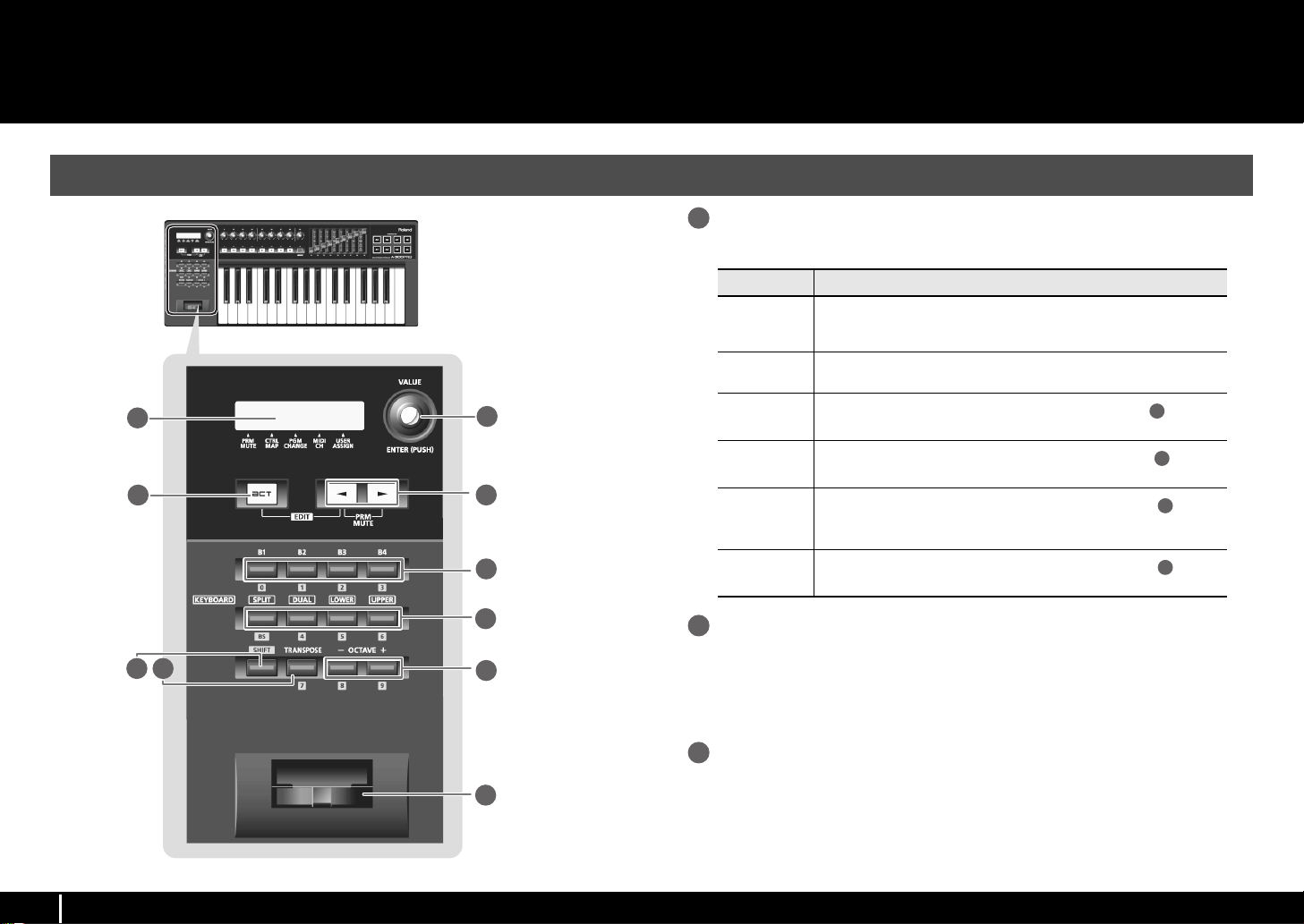
Display
1
This shows a variety of information, such as the current state.
Indication Summary
Alphanumeric
characters
PRM MUTE
CTRL MAP
PGM CHANGE
MIDI CH
USER ASSIGN
When you operate a controller, the value of the parameter assigned to that
controller is shown for a certain duration. Information such as the MIDI channel and program change is also shown.
When the cursor is located here, moving a controller will not transmit MIDI
messages (p. 47).
When the cursor is located here, you can turn the [VALUE] knob to switch
between control maps stored in the A-PRO (p. 21).
When the cursor is located here, you can turn the [VALUE] knob to transmit a program change on the current channel (p. 43).
When the cursor is located here, you can turn the [VALUE] knob to
change the MIDI channel on which the keyboard or bender lever will transmit (p. 42).
When the cursor is located here, you can turn the [VALUE] knob to
change the value of a user-assigned parameter (p. 68).
[VALUE] knob, [ENTER] button
2
2
2
You can turn the [VALUE] knob to change the MIDI channel, switch program changes
or control maps, or change the value of a user-specified parameter.
In EDIT mode, use the [VALUE] knob to select an item or edit its value.
When this knob is pressed, it functions as the [ENTER] button.
[ACT] button
3
Press the [ACT] button if you’re using SONAR or software compatible with ACT (Active
Controller Technology) (p. 21).
You can use controllers [B1]–[B4], [R1]–[R9], [L1]–[L9], [S1]–[S9], and [A1]–[A8] to
operate SONAR or your ACT-compatible software.
8
Page 9

Names of Things and What They Do
5
6
7
8
9
[ ] button, [ ] button
4
You can use the [ ] [ ] buttons to move the cursor that is shown at CTRL MAP,
PGM CHANGE, MIDI CH, or USER ASSIGN in the display.
Controllers [B1]–[B4] (button)
You can assign any desired MIDI messages to these buttons.
0 “Assigning MIDI Messages” (p. 29)
[SPLIT] button, [DUAL] button, [LOWER] button, [UPPER] button
[SPLIT] button
Use this button to split the keyboard into right (UPPER) and left (LOWER) areas so that
you can play a different sound in each area.
[DUAL] button
Use this button to play two sounds layered.
[LOWER] button
Use this button to play the LOWER part.
[UPPER] button
Use this button to play the UPPER part.
[SHIFT] button
When you’re in PLAY mode (p. 41), you can hold down the [SHIFT] button and use
controllers [B1]–[B4], the [DUAL]/[LOWER]/[UPPER] buttons, the [TRANSPOSE] button,
and the OCTAVE [–] [+] buttons as a numeric keypad. Hold down the [SHIFT] button and
press the [SPLIT] button for backspace.
Bender lever
10
Use this to change the pitch or apply vibrato.
You can also assign a desired MIDI message to this lever as a controller.
0 “Assigning MIDI Messages” (p. 29)
[TRANSPOSE] button
This button lets you shift the pitch of the keyboard up or down in steps of a semitone.
0 “TRANSPOSE” (p. 62)
OCTAVE [–] [+] buttons
These buttons let you shift the pitch of the keyboard up or down in steps of one octave.
9
Page 10
Names of Things and What They Do
13
14
15
11
12
12
fig.Panel-Top.eps
10
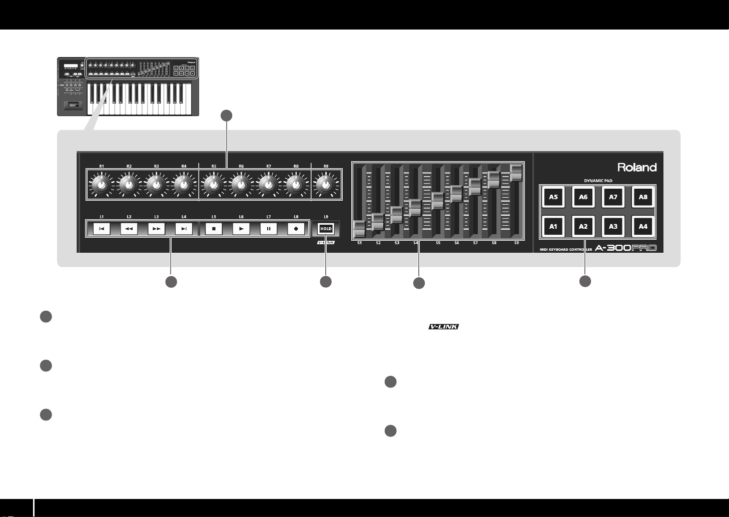
Controllers [R1]–[R9] (knobs)
11
You can assign the desired MIDI messages to these knobs.
0 “Assigning MIDI Messages” (p. 29)
Controllers [L1]–[L8] (button)
You can assign the desired MIDI messages to these buttons.
0 “Assigning MIDI Messages” (p. 29)
[HOLD] button
13
This button turns Hold on/off (a function that sustains the note even after you release
the [A1]–[A8] pad).
Alternatively, you can assign a desired MIDI message to this button or use it to turn
V-LINK on/off instead of using it as Hold.
0 “L9 FUNCTION” (p. 69)
V-LINK
V-LINK ( ) is a function that allows music and images to be performed
together. By using MIDI to connect two or more V-LINK compatible devices, you can
easily enjoy a wide range of visual effects that are linked to the expressive elements of
a music performance.
Controllers [S1]–[S9] (sliders)
14
You can assign the desired MIDI messages to these sliders.
0 “Assigning MIDI Messages” (p. 29)
Controllers [A1]–[A8] (pads)
15
You can assign the desired MIDI messages to these pads.
0 “Assigning MIDI Messages” (p. 29)
These pads can transmit velocity values that correspond to the force with which you
pressed the pad, or aftertouch values.
Page 11
Side Panel
18
19
20
21
22
17
16
19
21
22
Names of Things and What They Do
fig.Panel-Side.eps
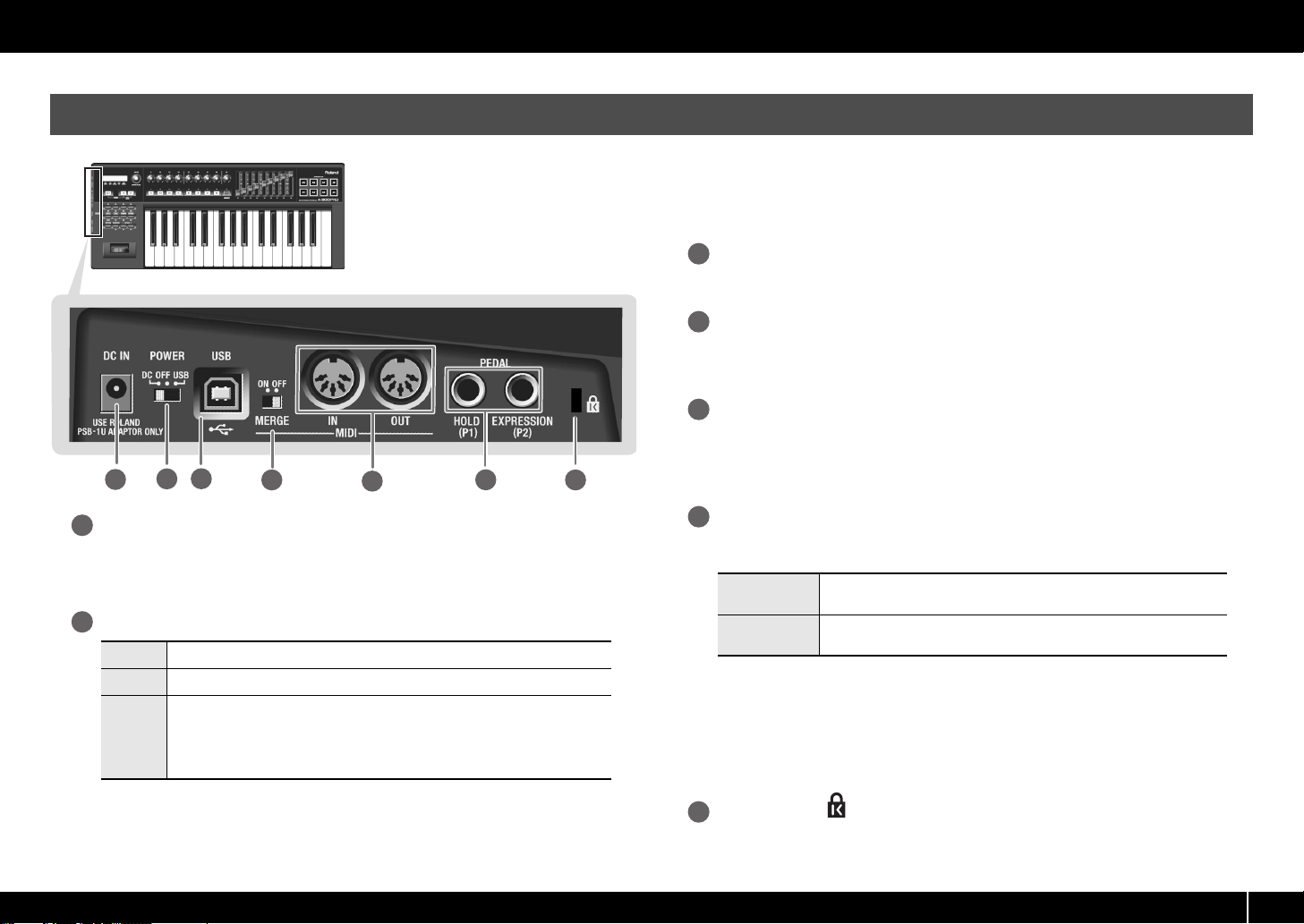
DC IN jack
16
You can connect a separately sold AC adaptor here. If you want to purchase an AC
adaptor, contact the retailer from whom you purchased the product, or the nearest
Roland Service Center.
[Power] switch
17
DC Power on using the AC adaptor
OFF Power off
Power on with the USB cable connected
USB
• When not connected to a computer, the unit will automatically be switched off four
hours after you stop playing or operating it (AUTO OFF function).
If you do not want the power to be turned off automatically, disengage the AUTO
OFF function (p. 70).
USB (i.e., bus power) can be used when the A-PRO is connected to your computer
via a USB cable. The power is supplied from the computer via the USB cable.
* The A-PRO might not operate on bus power with some computers. In this case,
please use the separately sold AC adaptor.
* Any settings that you are in the process of editing will be lost when the power is
turned off. If you have any settings that you want to keep, you should save them
beforehand.
* To restore power, turn the power on again.
USB connector
18
Use this to connect the A-PRO to your computer via a USB cable.
[MIDI MERGE] switch
This switch turns the Merge function on/off for messages from MIDI IN.
0 “MIDI MERGE DESTINATION” (p. 67)
MIDI IN/OUT connectors
20
You can connect these connectors to the MIDI connectors of other MIDI equipment to
transmit and receive MIDI messages.
0 “MIDI-related Settings” (p. 66)
HOLD (P1) jack, EXPRESSION (P2) jack
Connect the appropriate type of pedal to each of these connectors.
HOLD
EXPRESSION
You can also assign any desired MIDI message to these controllers.
0 “Assigning MIDI Messages” (p. 29)
* Use only the specified expression pedal (EV-5 or EV-7; sold separately). By
connecting any other expression pedals, you risk causing malfunction and/or
damage to the unit.
Connect a pedal switch (DP-2, DP-10; sold separately) here and use it as a
Hold pedal.
Connect an expression pedal (EV-5, EV-7; sold separately) here and use it to
control the sound or volume in real time.
Security slot ( )
http://www.kensington.com/
11
Page 12

Installing the Driver
1.
2.
Install driver
Windows 8 /
Windows 7 /
Windows Vista
P. 12
P. 19
P. 15
P. 19
P. 17
P. 20
Windows XP Mac OS X
Check
To open the Control Panel Windows 8 users
1. On the Start screen, click the Desktop.
2. Move the mouse pointer to the upper right or lower right corner of the
screen to display the charms.
* On touch-enabled PCs, swipe from the right side of the screen to display the
charms.
3. Click [Settings] and display the “Settings charms.”
4. In “Settings charms,” click [Control Panel] to open the “Control Panel.”
A driver is software that transfers data between the A-PRO and the application software
on your computer when the A-PRO is connected to your computer.
Windows 8/Windows 7/Windows Vista Users
Refer to the Roland website for the latest drivers and information about compatibility
with the latest operating system versions.
http://www.roland.com/support/
The procedure for installation and checking will depend on your system. Perform the
following two steps to install and check the driver.
fig.H_install.eps
Steps to be performed on the A-PRO keyboard itself are marked by a
Operation of the A-PRO
are told to do so.
* The example screen shots included here are taken from Windows 7.
symbol. Don’t connect the A-PRO to your computer until you
1 With the A-PRO disconnected, start up Windows.
Disconnect all USB cables from your computer, with the exception of those for a
USB keyboard and USB mouse (if used).
Windows 8 users
Switch to the “Desktop.”
2 Close all currently running software.
3 Insert the included A-PRO CD-ROM into your CD-ROM drive.
4 In the [Driver] folder within the CD-ROM, double-click the [Setup]
icon to start up the installer.
Windows 8/Windows 7 users
Open “Control Panel,” click “System and Security,” and then click [System].
If the Control Panel shows the icon view, click [System].
12
Page 13
Installing the Driver
Operation of the A-PRO
Operation of the A-PRO
Operation of the A-PRO
Windows Vista users
Open “Control Panel,” click [System and Maintenance], and then click [System].
If the Control Panel shows the classic view, double-click the “System” icon.
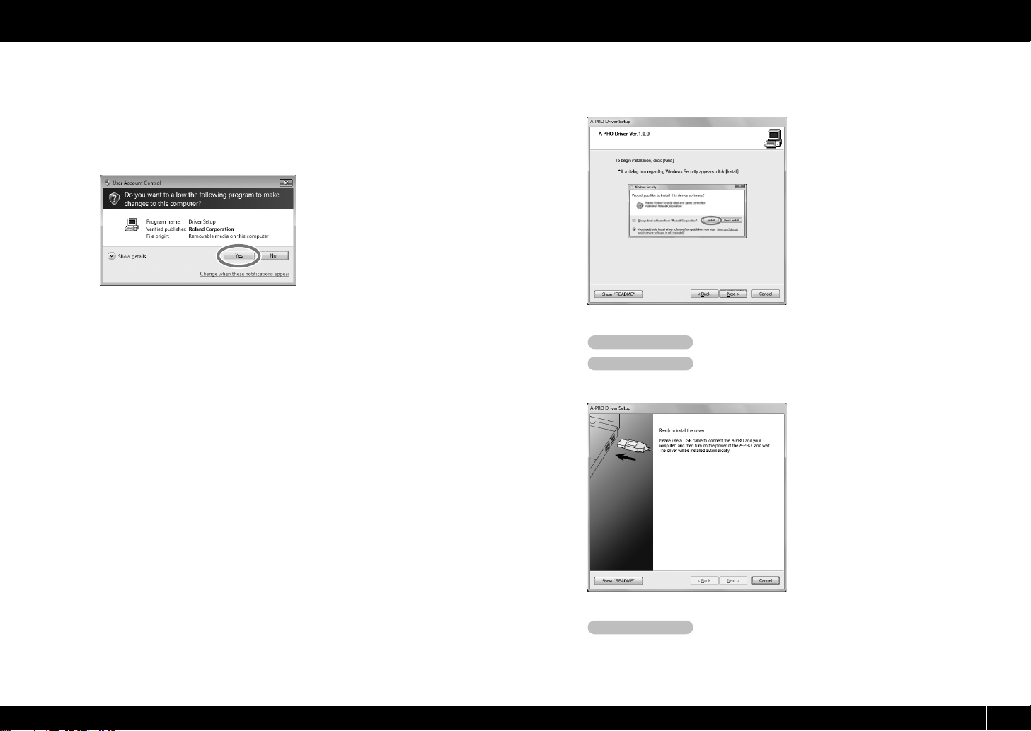
5 A user account control confirmation screen will appear.
Click [Yes] or [Continue].
fig.win7uac_e.eps
6 The screen will indicate “A-PRO Driver will be installed on your
computer.” Click [Next].
If any other message appears, proceed as directed by the message.
7 To begin the installation, click [Next] once again. Installation will
begin.
fig.win7securitya-e.eps_36
If a Windows security dialog box appears, click [Install].
8 Turn the A-PRO’s [POWER] switch OFF.
9 When the screen indicates “Ready to install the
driver,” use a USB cable to connect the A-PRO to your computer.
fig.win7drv3-e.eps_36
If any other message appears, proceed as directed by the message.
10 Set the A-PRO’s [POWER] switch to USB.
The driver will be installed automatically.
13
Page 14

Installing the Driver
11 When the installation is completed, the “A-PRO Driver Setup” dialog
box will indicate “Installation has been completed.”
Click [Close] to close the “A-PRO Driver Setup” dialog box.
If the “System Settings Change” dialog box appears, click [Yes]. Windows will
automatically restart.
Now let’s check to make sure that installation was successful.
0 “Checking with a SONAR Soft Synths (Windows)” (p. 19)
14
Page 15
Windows XP Users
Operation of the A-PRO
Operation of the A-PRO
Operation of the A-PRO
Operation of the A-PRO
Steps to be performed on the A-PRO keyboard itself are marked by a symbol. Don’t connect the A-PRO to your computer until you are told to do so.
Installing the Driver
1 With the A-PRO disconnected, start up Windows.
Disconnect all USB cables from your computer, with the exception of those for a
USB keyboard and USB mouse (if used).
2 Close all currently running software.
3 Insert the included A-PRO CD-ROM into your CD-ROM drive.
4 On the CD-ROM, open the [Driver] folder and double-click the
[Setup] icon.
If you get a message saying “The operating system you are using is not supported”
or saying that the application is invalid, check the version of your operating
system.
If the “Install Program As Other User” dialog box appears, click [Cancel] to
terminate the installation, log on to Windows using an administrator account, and
perform the installation once again.
5 The screen will indicate “A-PRO Driver will be installed on your
computer.” Click [Next].
If any other message appears, proceed as directed by the message.
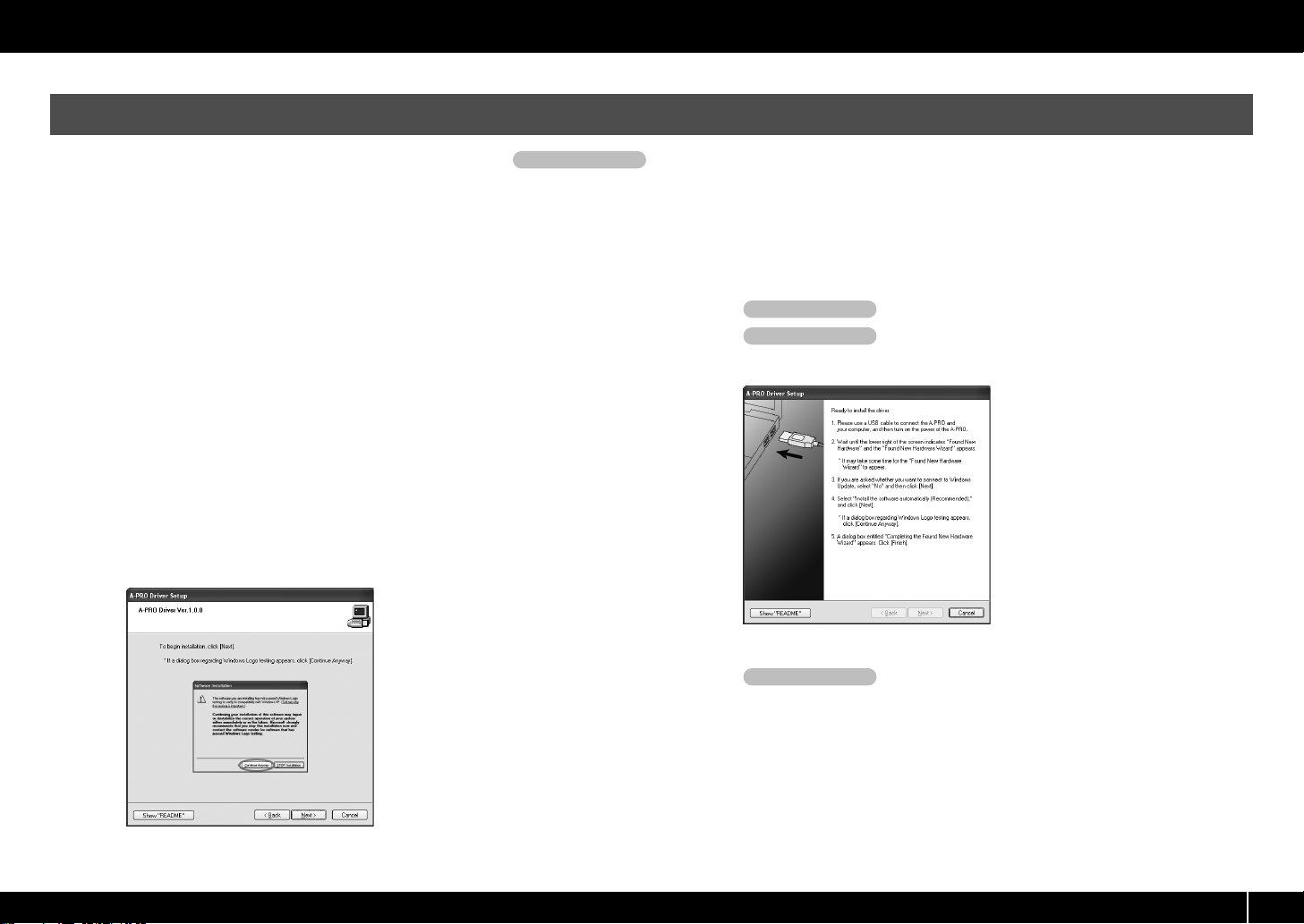
6 To begin the installation, click [Next].
fig.xpdrv2-e.eps_27
If the “Software Installation” dialog box appears, click [Continue Anyway] to
continue the installation.
If you are unable to proceed, click [OK] in the dialog box to terminate the
installation. Then change the setting as described in “Driver signing options
setting (Windows XP)” (p. 80), and perform the installation once again.
7 Set the A-PRO’s [POWER] switch to OFF.
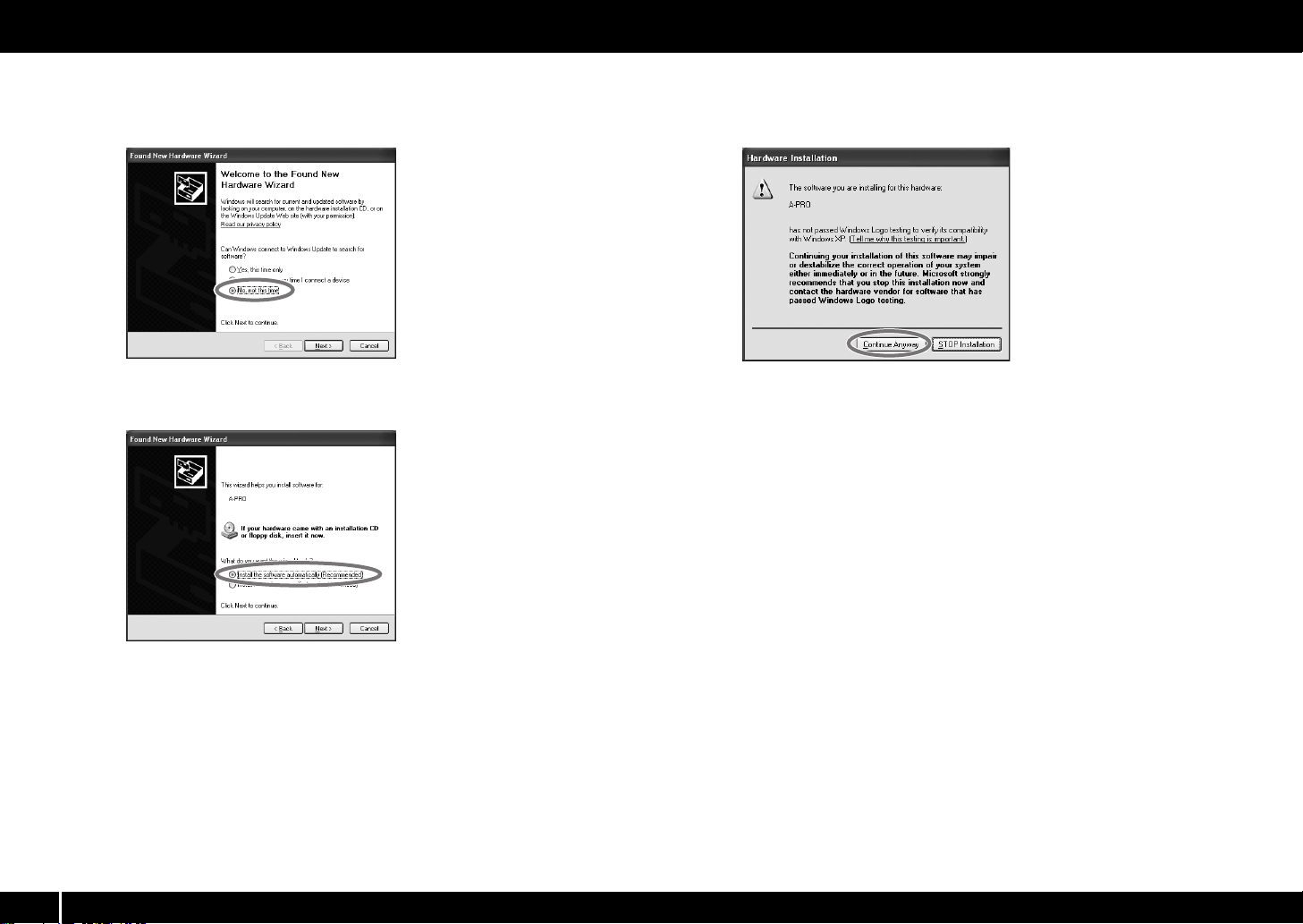
8 When the “Ready to install the driver” message
appears, use a USB cable to connect the A-PRO to your computer.
fig.xpdrv4-e.eps_27
If any other message appears, proceed as directed by the message.
9 Set the A-PRO’s [POWER] switch to USB.
The indication “Found New Hardware” will appear in the lower right corner of your
screen.
* It may take between ten seconds to several minutes for the “Found New Hardware
Wizard” to appear.
15
Page 16
Installing the Driver
10 If you are asked whether you want to connect to Windows Update,
choose [No, not this time] and click [Next].
fig.xpwupd-e.eps
11 Choose [Install the software automatically (Recommended)], and
click [Next].
fig.xpdrv6-e.eps
12 If the “Hardware Installation” dialog box appears, click [Continue
Anyway] to continue the installation.
fig.xpdrv7-e.eps
If you are unable to proceed, click [OK] in the dialog box to terminate the
installation. Then change the setting as described in “Driver signing options
setting (Windows XP)” (p. 80), and perform the installation once again.
13 The screen will indicate “Completing the Found New Hardware
Wizard.” Click [Finish].
14 When installation is complete, the “A-PRO Driver Setup” dialog box
will indicate “Installation has been completed.”
Click [Close] to close the “A-PRO Driver Setup” dialog box.
If the “System Settings Change” dialog box appears, click [Yes] to restart Windows.
Now let’s check to make sure that installation was successful.
This completes driver installation and settings.
0 “Checking with a SONAR Soft Synths (Windows)” (p. 19)
16
Page 17
Operation of the A-PRO
Operation of the A-PRO
Operation of the A-PRO
Operation of the A-PRO
Mac OS X Users
Steps to be performed on the A-PRO keyboard itself are marked by a symbol. Don’t connect the A-PRO to your computer until you are told to do so.
Installing the Driver
* If a dialog box requesting a password appears during installation, enter a computer
administrator’s user name and password and click the [Install Software] button or
[OK] button.
* What you actually see on the screen may differ depending on your system.
1 With the A-PRO disconnected, start up your computer.
Disconnect all USB cables from your computer, with the exception of those for a
USB keyboard and USB mouse.
2 Close all currently running software.
3 Insert the included A-PRO CD-ROM into your CD-ROM drive.
4 On the CD-ROM, open the [Driver] folder and double-click the
[APRO_USBDriver] icon to start the installer.
A message concerned with checking whether installation is possible may appear.
If so, click [Continue].
If a message indicating that installation is not possible appears, check the
operating system you’re using, and perform step 4.
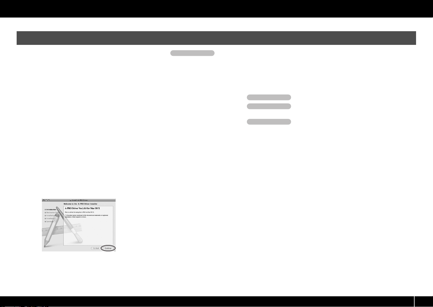
5 The screen will indicate “Welcome to the A-PRO Driver Installer.”
Click [Continue].
fig.osx-install-e.eps
8 In the next screen, click [Continue Installation].
9 When installation is completed, click [Restart] to restart your
computer.
* It may take some time for your computer to restart.
10 Set the A-PRO’s [POWER] switch to OFF.
11 When your computer has restarted, use a USB
cable to connect the A-PRO to your computer.
12 Set the A-PRO’s [POWER] switch to USB.
13 Double-click [Audio MIDI Settings] (/Applications/Utility) to start it
up.
14 Access the dialog box.
Mac OS X 10.6 or later
From the [Window] menu, choose [Show MIDI Window] to open “MIDI Studio”
Mac OS X 10.5 or earlier
Click the [MIDI Devices] tab.
6 If the screen asks you to select a destination, click your start-up disk
7 When the display asks you to select the type of installation, click
to select it, and then click [Continue].
[Install] or [Upgrade].
17
Page 18
Installing the Driver
15 Verify that [A-PRO] is shown in the “MIDI Studio” or “Audio MIDI
Settings” dialog box.
fig.osxaudiomidi1-e.eps
If the A-PRO is not shown or is grayed-out, the A-PRO has not been recognized
correctly. Try clicking [Rescan MIDI]. You can also try disconnecting the USB cable
connected to the A-PRO, then re-connecting it.
16 Click [Add Device] five times.
fig.osxadddevice-e.eps
Five [New Device] items will appear.
17 Specify the device name for each [New Device].
1. Select the [New Device] you added, and click [Show Info].
2. Enter the name in the [Device Name] field. For each [New Device],
fig.osxnewdevice-e.eps
enter the following names.
New Device Device Name
First A-PRO MIDI OUT
Second A-PRO
Third A-PRO MIDI IN
Fourth A-PRO 1
Fifth A-PRO 2
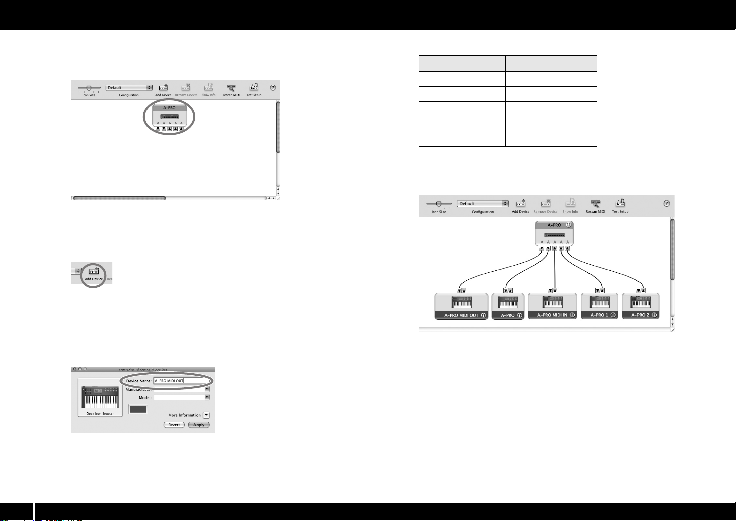
18 Use the mouse to drag between the H and I symbols (representing
input and output, respectively) of [A-PRO] and each [New Device] so
that they are connected as shown in the illustration below.
fig.osxmidiset-e.eps_32
19 Close the “MIDI Studio” dialog box or “Audio MIDI Setup” dialog
box.
Now let’s check to make sure that installation was successful.
0 “Checking in GarageBand (Mac OS X)” (p. 20)
18
Page 19
Verifying that Installation was Successful
Proceed as follows to verify that the driver was installed correctly.
We will use SONAR LE as an example for Windows, and GarageBand as an example for Mac OS X.
Checking with a SONAR Soft Synths (Windows)
Installing the Driver
Here’s an example using a plug-in synth included with SONAR LE. The procedure or
screens may differ if you’re using a different version.
1 Start up SONAR LE.
2 From the [EDIT] menu, click [Preferences...], and from the left menu
click [Devices] in the MIDI field.
The screen in which MIDI input/output devices are selected appears.
3 Choose the following MIDI devices in the [Inputs] and [Outputs]
fields.
Inputs Outputs
A-PRO MIDI IN
A-PRO 1
A-PRO 2
If you’re unable to select A-PRO as an input/output device, it may be that a
problem has occurred.
Refer to “Problems with Settings” in the Troubleshooting section (p. 76).
A-PRO
A-PRO MIDI OUT
4 Click [Apply], then [Close] to close the Preferences dialog box.
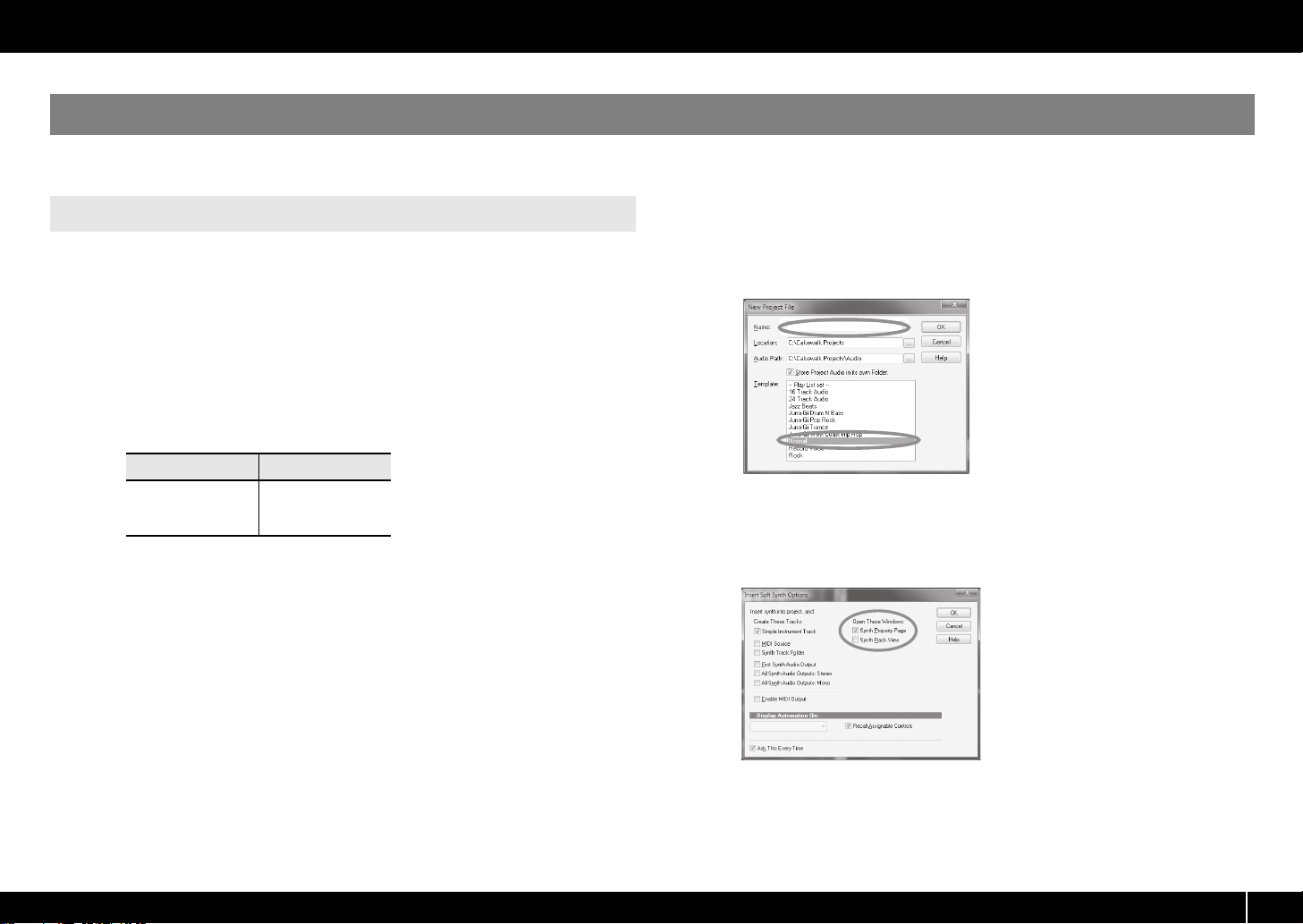
5 In the [File] menu, click [New].
The “New Project File” dialog box will appear.
6 In the “Template” area, choose [Normal]; then enter a project name
in the “Name” field and click [OK].
fig.sonarnew.eps
7 In the [Insert] menu, choose [Soft Synths] and then [Square I].
8 In the “Insert Soft Synth Options” dialog box, select the [Synth
Property Page] option in the [Open These Windows] area, and click
[OK].
fig.sonarinsertoption-e.eps_34
9 Play the A-PRO’s keyboard.
If the MIDI monitor in the taskbar responds and you hear the sound of the synth, the
A-PRO is correctly connected to your computer.
19
Page 20
Installing the Driver
Checking in GarageBand (Mac OS X)
GarageBand is software that is included with Apple’s iLife.
Here, the explanation assumes that you’re using GarageBand ‘11. The steps or screens
may be different if you’re using a different version.
1 In the [Applications] folder, double-click [GarageBand].
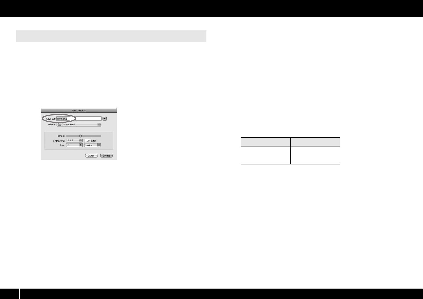
2 When GarageBand has started up, click the [File] menu item [New].
3 In the “New Project” screen, assign a name and click [Create].
fig.garageband_e.eps
4 Play the A-PRO’s keyboard.
If you hear the Grand Piano sound that’s assigned to the GarageBand track, the A-PRO
is correctly connected to your computer.
If you don’t hear sound, check the following points.
• From the [GarageBand] menu, click [Preferences]. If MIDI input is not detected in
the [Audio/MIDI] tab’s “MIDI Status” field, it may be that a problem has occurred.
Please refer to “Problems with setup” in the Troubleshooting section (p. 76).
• In “System Preferences,” choose the [Sound]-[Output] tab. Make sure that your
computer’s main volume is not turned down or muted. Also make sure that internal
audio is selected.
•If you’re using headphones, make sure that they are correctly connected to your
computer’s headphone jack.
• If you have an audio interface that’s connected to your computer, refer to the
owner’s manual of your device to make sure that your audio interface is connected
correctly.
If you don’t hear sound in software other than GarageBand, you’ll need to make MIDI
and audio input/output settings. Make the following settings for MIDI input/output.
Input device Output device
A-PRO MIDI IN
A-PRO 1
A-PRO 2
A-PRO
A-PRO MIDI OUT
20
Page 21

Look what You Can Do with the A-PRO
What is ACT?
ACT (Active Controller Technology) is functionality that lets you control SONAR
from an external device such as the A-PRO. This lets you control the plug-in effect
or plug-in synthesizer that’s active in SONAR without having to make timeconsuming settings.
About Control Maps
A Control Map is an object that describes how MIDI settings are assigned to the
various controllers.
By using Control Maps, you can easily switch to the settings you need for a
particular environment, making it easier for you to use a variety of different
software programs.
Play
When playing the A-PRO’s keyboard, you can select sounds in your sound module from
the A-PRO. You can also play two sounds together (DUAL) or separately (SPLIT).
For details, refer to “Performing (Play Mode)” (p. 41).
Use ACT
If you’re using SONAR, you can use the A-PRO as a controller for SONAR simply by
pressing the A-PRO’s [ACT] button to turn it on.
For details, refer to SONAR’s online help.
Use Control Maps
The A-PRO provides 19 control maps, and you can control a variety of software simply
by switching between them.
For details, refer to the separate Control Map Guide.
Create Your Own Settings
The A-PRO provides 44 controllers; you can freely assign a MIDI message to each
controller.
For details, refer to “Using A-PRO Editor” (p. 22).
21
Page 22
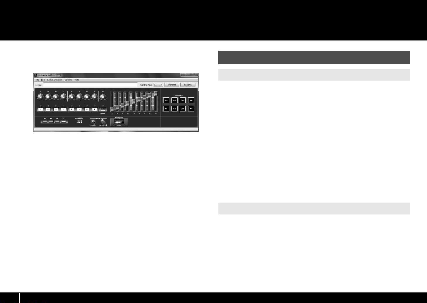
Using A-PRO Editor
A-PRO Editor is software that lets you create control maps (p. 21) for the A-PRO series
on your computer, and make settings for the keyboard. The graphical screen makes it
easy to edit the values (settings).
fig.editor-mainwindow-e+.eps_39
The A-PRO has a total of 44 controllers: [B1]–[B4], [R1]–[R9], [L1]–[L9], [S1]–[S9], [A1]–
[A8], HOLD (P1), EXPRESSION (P2), BENDER, MODULATION, and AFTERTOUCH. You can
freely assign any MIDI message to be controlled by each controller.
The 44 message assignments for these controllers are collectively called a “control
map.”
Simple assignments of MIDI messages can be made on the A-PRO keyboard itself
without using the editor software. However, A-PRO Editor also allows you to transfer
control map data in and out of the A-PRO keyboard, to edit control map data, and also
to save or load control map settings as SMF format data.
0 “Assigning a MIDI Message on the A-PRO Keyboard” (p. 48)
Installing A-PRO Editor
Windows Users
1 Insert the included A-PRO CD-ROM into your CD-ROM drive.
2 On the CD-ROM, open the [EDITOR] folder and double-click [SETUP]
to start the installer.
3 The screen “Welcome to the InstallShield Wizard for A-PRO Editor
Setup” will appear. Click [Next].
4 When the “Please Read” screen appears, read the contents, and if
you consent, click [Yes].
You cannot install A-PRO Editor unless you consent to the terms.
5 A dialog box will allow you to specify the installation location.
Simply click [Next].
6 Verify the contents of the “Confirmation of installation” screen, and
then click [Next].
Copying of the files will begin.
7 When copying is completed, click [Finish].
This completes installation of the A-PRO Editor.
22
Mac OS X Users
1 Insert the included A-PRO CD-ROM into your CD-ROM drive.
2 From the CD-ROM’s [Editor] folder, drag the [A-PRO Editor] folder
and drop it into your Mac’s [Applications] folder to copy it.
This completes installation of the A-PRO Editor.
Page 23
MIDI Port Assignments
What is a MIDI port?
A MIDI port is a port used to transfer MIDI messages between your computer
and the A-PRO.
Input ports
The output destination of the MIDI messages transmitted when you operate
the A-PRO’s sliders, knobs, and buttons can be specified separately for each
controller. For details, refer to “Two MIDI Ports” (p. 71).
Output ports
In order to transmit a control map created using A-PRO Editor to the A-PRO,
you must choose [A-PRO] as the output port.
Input port Explanation
A-PRO MIDI IN Receives data that’s input via the A-PRO’s MIDI IN connector.
A-PRO 1
Receives data from A-PRO sliders, knobs, or buttons that are
assigned to “PORT 1.”
A-PRO 2
Receives data from A-PRO sliders, knobs, or buttons that are
assigned to “PORT 2.”
When receiving bulk data from the A-PRO, choose [A-PRO 2]
as the input port.
Output port Explanation
A-PRO MIDI OUT
Transmits MIDI messages to MIDI devices connected to the
A-PRO’s MIDI OUT connector.
A-PRO
Transmits MIDI messages to the A-PRO.
When transmitting bulk data from the A-PRO, choose [A-PRO]
as the output port.
In order to transfer control maps between A-PRO Editor and the A-PRO keyboard, you’ll
need to specify the MIDI ports used by A-PRO Editor.
* If the A-PRO is connected via USB, the ports will be as follows. If you’re using a MIDI
connection, specify the MIDI input port and MIDI output port of the MIDI device to
which the A-PRO is connected, instead of “A-PRO 2” and “A-PRO.”
Using A-PRO Editor
Windows Users
1 Use a USB cable to connect the A-PRO to your computer, then switch
on the A-PRO’s power.
2 Click the Windows [Start], then successively click [All Programs],
[A-PRO Editor], and [A-PRO Editor] to start up A-PRO Editor.
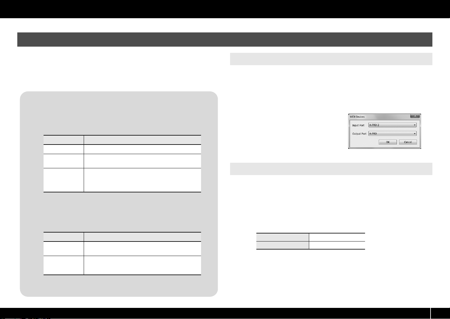
3 In A-PRO Editor, click the [Options] menu item [MIDI Devices].
fig.editor-device-e.eps
4 In the MIDI Devices dialog box,
specify the MIDI devices as shown
in the illustration.
5 Click [OK] to close the dialog box.
Mac OS X Users
1 Use a USB cable to connect the A-PRO to your computer, then switch
on the A-PRO’s power.
2 Double-click [A-PRO Editor] (/Applications/A-PRO Editor/) to start up
A-PRO Editor.
3 In A-PRO Editor, click the [Options] menu command [MIDI Devices].
4 In the MIDI Devices dialog box, specify the MIDI devices as follows.
Input port A-PRO 2
Output port A-PRO
5 Click [OK] to close the dialog box.
23
Page 24
Using A-PRO Editor
2
1
2
3
4
6
5
1
2
Items in the Windows
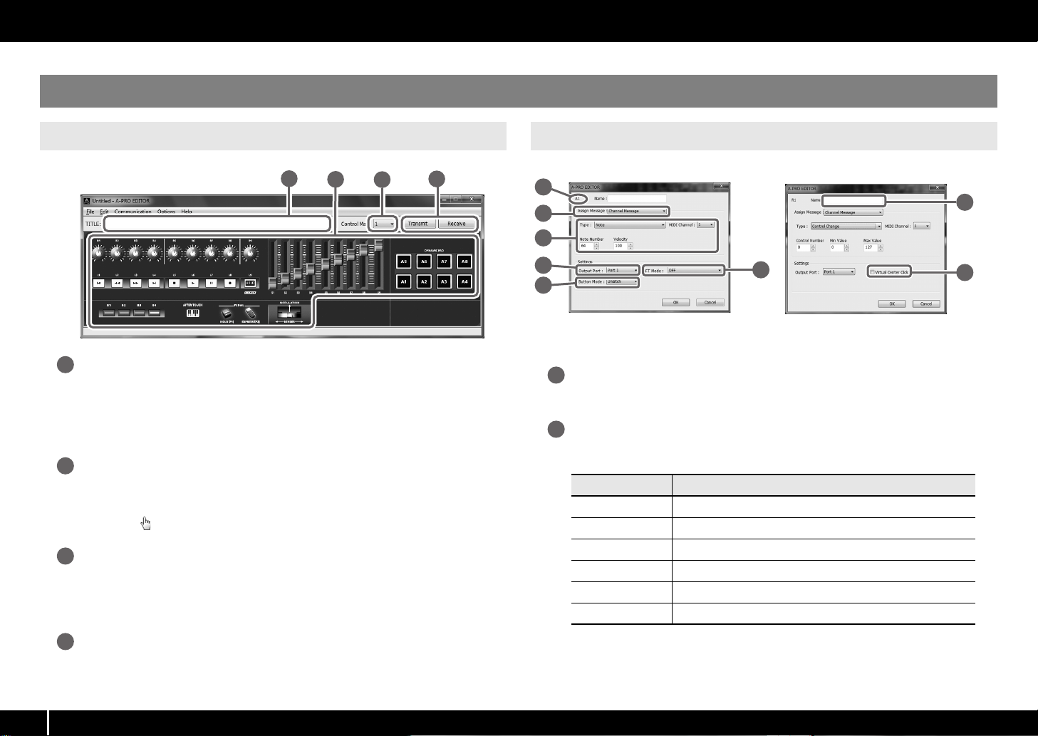
Main Window
fig.editor-mainwindow-e.eps
1
3
1
2
3
4
Title
You can assign a name to the control map you’re editing. Only single-byte
alphanumeric characters can be entered for the control map name. The name you
enter here is shown as the title of the HTML file that’s exported by the [File] menu
command [Export Assign List].
Controllers
Here you can click to select the controller to which you want to assign a MIDI message.
When you move the mouse over a controller (a clickable area), the mouse cursor will
change to a . Now you can click the controller to open the Assign Message window.
[Control Map] dropdown list
Here’s where you select the number of the control map that you want to edit.
For details, refer to “Receiving a Control Map from the A-PRO” (p. 31), and
“Transmitting a Control Map to the A-PRO” (p. 31).
Message Assignment Window
fig.editor04-num-e.eps, fig.edito r05-num-e.eps
7
8
* The items in the window will differ depending on the controller and on the type of
message being assigned.
Controller name
This shows the name of the controller you’re editing.
Assign Message selection list
Here you can select the type of MIDI message to be assigned to the controller.
Menu Explanation
NO ASSIGN No MIDI message will be assigned
Channel Message Channel messages (CC, note, etc.)
System Realtime/F6 System realtime message or F6 (Tune Request)
System Ex. System exclusive message of up to 24 bytes
Free Message Any MIDI message of up to 24 bytes (multiple messages are allowed)
Tempo Tempo control
24
[Transmit], [Receive]
4
Click [Transmit] to save a control map to the A-PRO, overwriting existing content. Click
[Receive] to load a control map from the A-PRO.
Page 25
Using A-PRO Editor
4
8
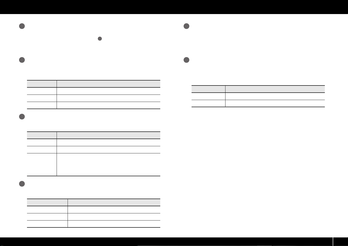
Message assignment area
3
Here you can specify the value of various parameters for the MIDI message you
2
selected in the Assign Message selection list
.
For details on the parameters of each MIDI message, refer to “Message Parameters” (p.
33)
Output Port
This specifies the USB port from which the MIDI messages will be transmitted to a USBconnected computer.
Port Explanation
Port 1 MIDI messages will be transmitted to “A-PRO 1.”
Port 2 MIDI messages will be transmitted to “A-PRO 2.”
Port 1+2 MIDI messages will be transmitted to both “A-PRO 1” and “A-PRO 2.”
Button Mode
5
If the controller is a button, this specifies the button mode.
Mode Explanation
Unlatch Turns on when you press the button; turns off when you release it.
Latch Alternately turns on/off each time you press the button.
Each time you press the button, the value will be incremented by one
(or decremented by one if the maximum value is below the minimum
Increase
value). When the value reaches the maximum value (minimum value),
it will jump back to the minimum value (maximum value).
* This cannot be selected if the message type is Note.
Name
7
You can enter a name to describe the function you’ve assigned to the controller; this
name is shown in the A-PRO’s display. Up to sixteen single-byte alphanumeric
characters can be entered. The name you enter here is shown in the “PARAMETER” field
of the HTML file exported by the [File] menu command [Export Assign List].
Virtual Center Click
If the c ont roll er y ou’r e ed itin g is [R1] –[R 9] o r [S1 ]–[ S9], you can m ake virt ual cent er c lick
settings (p. 55).
This broadens the range in which the center value is transmitted.
Mode Explanation
OFF No insensitive range in the center
ON Insensitive range in the center
Aftertouch mode (AFT Mode)
6
If the controller you’re editing is [A1]–[A8], you can specify the aftertouch setting.
Mode Explanation
OFF No aftertouch
Channel Pressure Transmitted as channel pressure messages
Polyphonic Key Pressure Transmitted as polyphonic key pressure messages.
25
Page 26
Using A-PRO Editor
6 7
1 2 3 4 5
8
What is a Keyboard Set?
Keyboard-related settings such as the MIDI channel and split point for the
UPPER and LOWER parts, and the octave settings, are collectively called a
“keyboard set.”
You can use A-PRO Editor to make keyboard set settings and store them to the
[SPLIT]/[DUAL]/[LOWER] buttons.
* Keyboard sets cannot be stored on your computer.
1
2
4
6
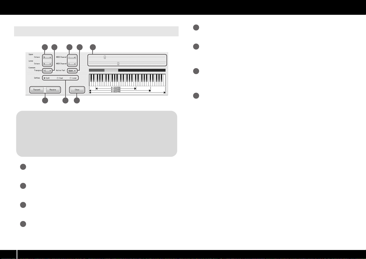
Keyboard Set Window
fig.keyboarset-e.eps
Keyboard range settings
5
Specify the lower limit of the UPPER part and the upper limit of the LOWER part.
[Transmit], [Receive]
Click [Transmit] if you want to save a keyboard set on the A-PRO. Click [Receive] if you
want to load a keyboard set from the A-PRO.
Setting buttons
7
Specify the button ([SPLIT]/[DUAL]/[LOWER]) for which you are assigning a keyboard
set.
[Close]
8
Closes the Keyboard Set window.
Octave shift
Specifies the octave of the UPPER and LOWER parts.
Transpose
Specifies the transposition of the keyboard.
MIDI Channel
3
Specifies the MIDI channel of the UPPER and LOWER parts.
Active Part
Specifies the part(s) to which the [VALUE] knob, BENDER, MODULATION, AFTERTOUCH,
HOLD, or EXPRESSION will apply.
26
Page 27
Menus
Using A-PRO Editor
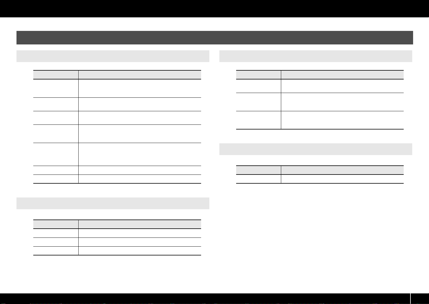
File Menu
New
Open
Save
Save As
Export Assign List
View Assign list Displays the assigned MIDI messages in your Web browser.
Recently Used Files Shows the names of the recently used files.
Edit Menu
Copy Copies the setting of the selected controller to the clipboard.
Paste Pastes the setting from the clipboard to the selected controller.
No Assign Sets the MIDI assignment of the selected controller to No Assign.
Menu Explanation
Creates a new control map.
The new control map will ha ve no MIDI messages assigned to any of
the controllers.
Loads a control map that was saved in SMF format. For details, refer
to “Loading a Control Map that was Saved on Your Computer” (p. 32).
Saves the control map currently being edited by overwriting the
SMF.
Saves the control map currently being edited in SMF format with the
name you specify. For details, refer to “Loading a Control Map that
was Saved on Your Computer” (p. 32).
Exports an HTML-format list of the messages assigned to each controller of the control map currently being edited.
* The HTML file created by this command cannot be loaded by
means of the [File] menu command [Open].
Menu Explanation
Options Menu
Menu Explanation
Show Keyboard Panel
MIDI Devices
Show Messages
Help Menu
Menu Explanation
About Displays the version of A-PRO Editor.
Changes the settings of the [LOWER], [DUAL], or [SPLIT] keyboard
set.
Specifies the MIDI ports used to communicate with the A-PRO keyboard.
For details, refer to “MIDI Port Assignments” (p. 23).
Shows the MIDI message settings assigned to each controller in the
main window of A-PRO Editor. For details, refer to “Checking t he Assigned MIDI Messages” (p. 30).
27
Page 28
Using A-PRO Editor
Keyboard Shortcuts
You can use the following keyboard shortcuts with A-PRO Editor.
Command
[File]–[New] Ctrl + N Command + N
[File]–[Open] Ctrl + O Command + O
[File]–[Save] Ctrl + S Command + S
[File]–[Save As] Ctrl + Shift + S Command + Shift + S
[File]–[Exit] Alt + F4 Command + Q
[Edit]–[Copy] Ctrl + C Command + C
[Edit]–[Paste] Ctrl + V Command + V
[Edit]–[NO ASSIGN] Del Del
Next controller Ctrl + F Command + F
Previous controller Ctrl + B Command + B
Key
(Windows)
Key
(Mac OS X)
In text boxes such as the Title field of the main window, keyboard shortcuts for the
[Edit] menu commands [Copy] and [Paste] can be used on the text.
28
Page 29
Using Control Maps
Assigning MIDI Messages
Using A-PRO Editor
Here’s how to assign a MIDI message to each controller.
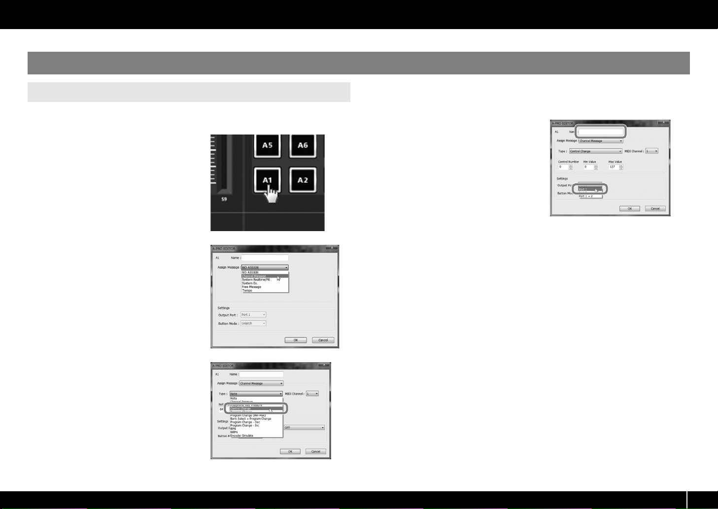
fig.editor-assign1.eps
1 In the main window, click the
controller to which you want to
assign a MIDI message.
fig.editor-assign2.eps
2 In the message assignment
window, use the Assign Message
field to select the type of MIDI
message you want to assign.
fig.editor-assign3.eps
3 According to the type of MIDI
message you selected, use the
fields of the message assignment
area to specify the parameters.
For details on the parameters, refer to
“Message Parameters” (p. 33).
fig.editor-assign4.eps
4 In the Output Port field, specify
the MIDI output port.
5 If desired, enter a name in the
Name field.
6 Click [OK].
29
Page 30

Using A-PRO Editor
Checking the Assigned MIDI Messages
You can use either of the following two methods to check the MIDI messages that are
assigned.
Viewing an assignment list
If you want to use your Web browser to view an assignment list of the current control
map, choose the [File] menu command [View Assign List].
This is a convenient way to view all of the control map’s settings.
If you want to save the assignment list as an HTML file, choose the [File] menu
command [Export Assign List...]. When the “Save As” dialog box appears, specify the
location, assign a file name, and then click [Save].
Viewing the assigned messages
If you want to see the current settings for each controller in the main window, choose
the [Options] menu command [Show Messages], and select the [Show Assigned
Messages] check box.
The current assignments will be shown in simplified form as follows.
fig.editor-assignmessage.eps
Indication Meaning
NO ASSIGN
Note
Channel Pressure
Polyphonic Key Pressure
Control Change
Program Change
Program Change (Min-Max)
Bank Select + Program Change
Program Change - Dec
Program Change - Inc
RPN
NRPN
Encoder Simulate
System Realtime/F6
System Ex.
Free Message
30
Tempo
The display color indicates the output port setting.
Display color Output Port
Yellow Port 1
Light blue Port 2
Light green Port 1 + 2
Pink NO ASSIGN
Page 31

Receiving a Control Map from the A-PRO Transmitting a Control Map to the A-PRO
Using A-PRO Editor
If you want to edit the control map settings of the A-PRO keyboard in A-PRO Editor, use
the following procedure to receive control map data from the A-PRO keyboard so that
it can be edited.
fig..editor-rcv1.eps
1 From the numbers displayed in the
[Control Map] dropdown list, select
the number of the control map that
you want to edit.
2 Click [Receive].
fig.editor-rev3-e.eps_50
3 In the confirmation dialog box, click
[Continue].
fig.editor-trans4-e.eps_40
4 A reception progress dialog box will
appear.
When the dialog box disappears, reception
has been completed.
If you want to use the control map settings created in A-PRO Editor on the A-PRO
keyboard, use the following procedure to transmit the edited control map to the A-PRO
keyboard.
fig.editor-trans1.eps
1 In the [Control Map] dropdown list,
specify the number at which you want
to save your control map.
2 Click [Transmit].
fig.editor-trans3-e.eps_50
3 In the confirmation dialog box, click
[Continue].
fig.editor-trans4-e.eps_40
4 A transmission progress dialog box
will appear.
When the dialog box disappears, transmission
has been completed.
31
Page 32

Using A-PRO Editor
Saving a Control Map on Your Computer Loading a Control Map that was Saved on Your
Control map settings you’ve edited in A-PRO Editor can not only be transferred directly
between the A-PRO keyboard and your computer, they can also be saved on your
computer as an SMF format file.
To save an SMF file, proceed as follows.
1 Choose the [File] menu command [Save As].
If you want to overwrite the most recently opened file, choose the [File] menu
command [Save].
2 Enter a file name and click [Save].
Computer
Control map data that was saved on your computer in SMF format can be loaded into
A-PRO Editor.
To load an SMF file, proceed as follows.
1 Choose the [File] menu command [Open].
2 Specify the SMF file that you want to load, and click [Open].
* An SMF file that does not contain A-PRO control map data cannot be opened. The
SMF must contain settings for all controllers.
* The contents of the Name field can be loaded only from an SMF that was saved by
A-PRO Editor.
* It is not possible to load control maps from the PCR-300/500/800 or memory sets
from an earlier PCR series unit.
32
Page 33

Message Parameters
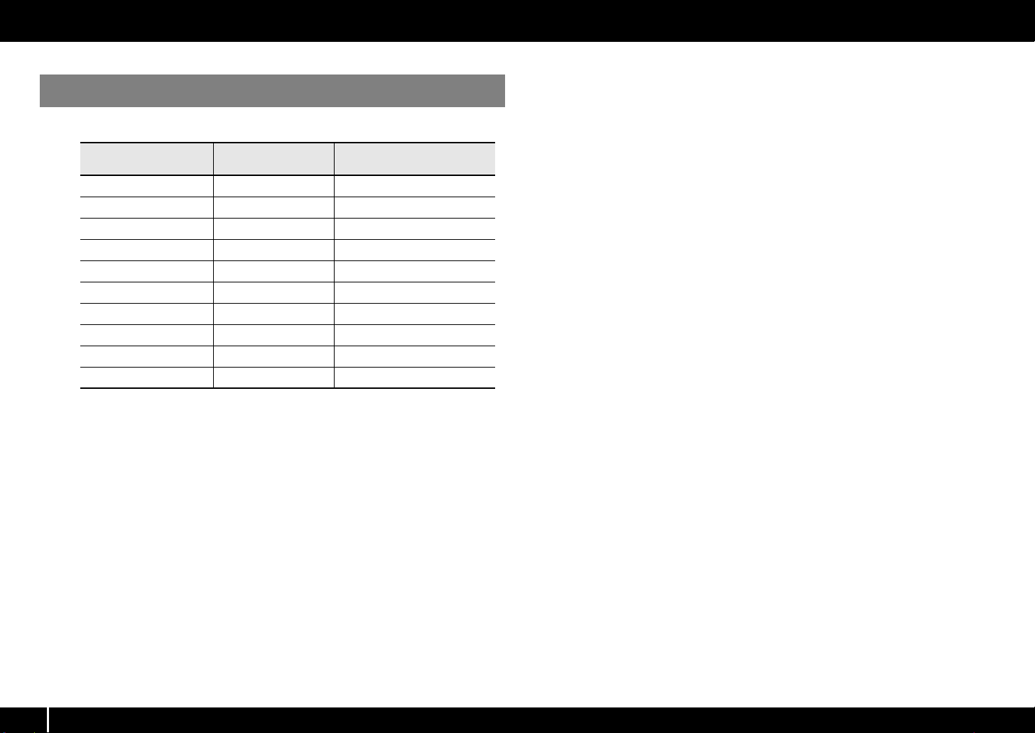
The setting items shown in the message assign window will depend on the MIDI message you’ve selected. This section explains the setting items for each MIDI message. Values for parameters
are specified in decimal.
For details on the Settings field, refer to “Message Assignment Window” (p. 24).
Using A-PRO Editor
NO ASSIGN
Clears any message assignment.
No message will be sent even if you operate a
controller that’s set to NO ASSIGN.
fig.editor-noassign.eps
There are no parameters to set.
* If HOLD, EXPRESSION, BENDER, MODULATION, or
AFTERTOUCH settings are set to NO ASSIGN, the
corresponding controller will control its own original
function. In this case, the current channel will be
used as the MIDI transmit channel.
Channel Message
Assigns a channel message.
Use the Type field to select the type of message you
want to assign. According to the message you’ve
selected, set the following parameters.
Note
Assign a note message.
fig.editor-note.eps
Specify the following parameters.
Item Content
MIDI Channel MIDI channel
Note Number Note number
Velocity Velocity
Channel Pressure
Assign a channel pressure message.
fig.editor-chpress.eps
Specify the following parameters.
Item Content
MIDI Channel MIDI channel
Min Value Lower value of channel pressure
Max Value Upper value of channel pressure
33
Page 34

Using A-PRO Editor
Channel Message
Polyphonic Key Pressure
Assign a polyphonic key pressure message.
fig.editor-poly.eps
Specify the following parameters.
Item Content
MIDI Channel MIDI channel
Note Number Note number
Min Value Lower value of key pressure
Max Value Upper value of key pressure
Control Change
Assign a control change message.
fig.editor-cc.eps
Specify the following parameters.
Item Content
MIDI Channel MIDI channel
Control Number Control number
Min Value Lower limit of the control value
Max Value Upper limit of the control value
Program Change
Assign a program change message (with a fixed
program number).
fig.editor-pc.eps
Specify the following parameters.
Item Content
MIDI Channel MIDI channel
PC Number Program number
* The range of the program number is 1–128.
34
Page 35

Channel Message
Using A-PRO Editor
Program Change (Min-Max)
Assign a program change message (with a variable
program number).
fig.editor-pcmm.eps
Specify the following parameters.
Item Content
MIDI Channel MIDI channel
Min Number Lower limit of the program number.
Max Number Upper limit of the program number.
* The range of the program number is 1–128.
Bank Select + Program Change
Assign a bank select message and program change
message (all values fixed).
fig.editor-bankpc.eps
Specify the following parameters.
Item Content
MIDI Channel MIDI channel
Bank MSB Bank number MSB
Bank LSB Bank number LSB
PC Number Program number
* The range of the program number is 1–128.
Program Change – Dec
Assign the program change decrement function (PC
DEC).
This will transmit a program change number that is one
less than the program change number most recently
transmitted in the A-PRO’s program change mode.
fig.editor-pcdec.eps
35
Page 36

Using A-PRO Editor
Channel Message
Program Change – Inc
Assign the program change increment function (PC
INC).
This will transmit a program change number that is one
greater than the program change number most
recently transmitted in the A-PRO’s program change
mode.
fig.editor-pcinc.eps
RPN
Assign a registered parameter number.
fig.editor-rpn.eps
Specify the following parameters.
Item Content
MIDI Channel MIDI channel
RPN MSB RPN parameter number MSB
RPN LSB RPN parameter number LSB
MSB Min Value Lower limit of data entry MSB
MSB Max Value Upper limit of data entry MSB
NRPN
Assign a non-registered parameter number.
fig.editor-nrpn.ep s
Specify the following parameters.
Item Content
MIDI Channel MIDI channel
NRPN MSB NRPN parameter number MSB
NRPN LSB NRPN parameter number LSB
MSB Min Value Lower limit of data entry MSB
MSB Max Value Upper limit of data entry MSB
36
* The range for the data entry LSB is fixed at 0–127 and
cannot be changed.
* The range for the data entry LSB is fixed at 0–127 and
cannot be changed.
Page 37

Using A-PRO Editor
Channel Message
Encoder Simulate
Assign a function that simulates a rotary encoder.
fig.editor-encsim.eps
Specify the following parameters.
Item Content
MIDI Channel MIDI channel
Control Number Controller number
* This can be assigned to a button, but will not do
anything.
System Realtime/F6
Assign a system realtime message or F6 (Tune Request).
fig.editor-realtime.eps
For System Realtime/F6, use the Status field to choose
the message you want to assign.
Item Content
F6 Tune request
F8 Timing clock
FA Start
FB Continue
FC Stop
FF System reset
37
Page 38

Using A-PRO Editor
Example of input
1. Enter the following in the message entry field.
F0 41 10 42 12 SS 40 1X 32 DT S1 F7
2.
In the Data Type field, choose “DT0.” Specify the
Min Value as “0” and the Max Value as “127.”
F0 41 10 42 12 SS 40 1x 32 DATA SUM F7
Block number 1 byte
Address Data
ChecksumChecksum calculation range
System Ex.
Assign a system exclusive message (System Ex.).
You can enter up to twenty-four bytes.
fig.editor-sysex.eps
Specify the following parameters.
Item Content
You can enter a system exclusive message of up to twenty-four bytes.
Enter each byte as a hexadecimal value separated by a single-byte space.
The following limitations apply to the input.
* The message must begin with “F0” and end with “F7.”
Message entry field
Data Type
Min Value Lower limit of the data value
Max Value Upper limit of the data value
38
* You cannot include more than one exclusive message.
* You cannot include messages other than an exclusive message.
You can enter variable data or a checksum using the special characters
described in “Table 1: Special characters used in the message en try field”
(p. 38). If you use the special character “DT,” use the Data Type field to
specify the type of data.
If you’ve used the special character “DT” in the message entry field, use
this to specify the type of data to be inserted at that location. For the
types of data that can be specified, refer to “Table 2: Types of data you
can specify in the Data Type field” (p. 38).
Table 1: Special characters used in the message entry field
Special
character
DT Data insertion location The data specified by Data Type will be inserted.
SS
S1/S2
?n
?x
Explanation Details
Beginning of checksum
calculation
Checksum insertion
location and type
Channel (? is any value
between 0–7)
Block number (? is any
value between 0–7)
If you use the automatic checksum calculation function, use
this special character to specify the point at which checksum calculation is to begin.
If you use the automatic checksum calculation function, use
this special character to specify the point at which the
checksum is to be inserted, and its type.
S1: The most common type, used by Roland and other man-
ufacturers.
S2: Choose this if a method other than S1 is used.
If you want a channel number to be inserted in the exclusive
message, use this special character to specify its location
and the upper four bits (a fixed value of 0–7). The current
channel of the A-PRO will be inserted in the chann el section.
If you want a GS block number to be inserted in the exclusive message, use this special character to specify its location and the upper four bits (a fixed value of 0–7). The
current channel of the A-PRO will converted into the block
number and inserted.
Table 2: Types of data you can specify in the Data Type field
Data type Data length Target of the specified Min Value / Max Value
DT0: 7-bit 1 byte Specifies a range from 0 to 127 (0–127)
DT1: 4-bit/4-bit 2 bytes
DT2: 7-bit/7-bit
(MSB/LSB)
DT3: 7-bit/7-bit
(LSB/MSB)
DT4: 4-bit/
4-bit/4-bit/4-bit
2 bytes
2 bytes
4 bytes
Specifies the range of the first byte (0–15)
* The second byte is fixed at 0–15
Specifies the range of the MSB (0–127)
* The LSB is fixed at 0–127
Specifies the range of the MSB (0–127)
* The LSB is fixed at 0–127
Specifies the range of change (0–255) between the negative direction (Min) and the positive direction (Max), centered on 8000h.
Page 39

Using A-PRO Editor
Free Message
Assign a MIDI message.
You can enter up to twenty-four bytes. You may assign more than one MIDI message if
desired.
fig.editor-freemsg.eps
Specify the following parameters.
Item Content
You can enter a MIDI message of up to twenty-four bytes. En ter each
byte as a hexadecimal value separated by a single-byte space.
The following limitations apply to the input.
Message entry field
Data Type
Min Value Lower limit of the data value
Max Value Upper limit of the data value
* You can’t use a checksum.
* You can’t use a special character as the first byte.
You can also enter variable data using the special characters described in “Table 1: Special characters used in the message entry
field” (p. 38). If you use the special character “DT,” use the Data Type
field to specify the type of data.
If you’ve used the special character “DT” in the message entry field,
use this to specify the type of data to be inserted at that location. For
the types of data that can be specified, refer to “Table 2: Types of
data you can specify in the Data Type field” (p. 38).
Tempo
Assign tempo control for transmitting MIDI CLOCK messages.
fig.editor-tempo.eps
There are no parameters to specify.
* This will not function if assigned to a button.
39
Page 40

Using A-PRO Editor
Using Keyboard Sets
Receiving a Keyboard Set Transmitting a Keyboard Set
If you want to edit a keyboard set, use the following procedure to load the keyboard
map data from the A-PRO, so that it can be edited.
fig.keyboardset1.eps
1 Use the [SPLIT]/[DUAL]/[LOWER]
buttons to select the keyboard set
that you want to edit.
fig.keyboardsetrecv.eps
2 Click [Receive].
3 In the confirmation box, click [Continue].
4 A reception progress dialog box will appear.
When the dialog box disappears, reception is complete.
If you want to use a keyboard set created in A-PRO Editor on the A-PRO keyboard,
proceed as follows to transmit it.
fig.keyboardset1.eps
1 Use the [SPLIT]/[DUAL]/[LOWER]
buttons to select the keyboard set
that you want to edit.
fig.keyboardsettrans.eps
2 Click [Transmit].
3 In the confirmation box, click [Continue].
4 A transmission progress dialog box will appear.
When the dialog box disappears, transmission is complete.
40
Page 41

Performing (Play Mode)
Use Play mode when you want to play the A-PRO’s keyboard or use its controllers to
control your software or sound modules.
Broadly speaking, the A-PRO has the following two modes.
Mode Explanation To select
This is the mode in which you play the keyboard
Play mode
Edit mode
(p. 48, p. 57)
and operate the controllers.
MIDI messages will be transmitted by each controller.
This is the mode in which you assign MIDI messages to each controller, or make system settings.
When you turn on the power, the A-PRO will start up in Play mode.
To return from Edit mode to Play mode, you can either press the [ACT] button and
[ ] button simultaneously, or hold down the [SHIFT] button and press the [SPLIT]
button ([BS] button). In this case, the settings you were in the process of making will be
discarded.
When you play the keyboard in Play mode, note messages will be transmitted, causing
your sound module to produce sound.
Playing the Keyboard
1. Turn on the power.
2. Exit EDIT mode.
1. From PLAY mode, press the
[ACT] button and [ ]
button simultaneously.
Convenient Performance Functions
Here are some of the functions you will find convenient when you’re performing.
Function Explanation
Changing the pitch of
a sounding note
(Pitch Bend)
Applying modulation
to a sounding note
(Modulation)
Switching the octave
(Octave Shift)
Changing the pitch
(Transpose)
Moving the bender lever to the left or right will transmit pitch bend messages, causing the pitch to change slightly.
* The range of the pitch change (“bend range”) will depend on the set-
tings of your sound module.
Moving the bender lever away from yourself will transmit modulation
messages (CC#01), applying a vibrato effect to the sound.
* The way in which the so und changes will depend on the settings of your
sound module.
You can use the OCTAVE [–] [+] buttons to raise or lower the keyboard’s
pitch range in steps of an octave (Octave Shift). Use this when you want to
shift the keyboard’s pitch range upward or downward.
Pressing the OCTAVE [–] button once will lower the pitch by one octave.
Pressing it again will lower the pitch by another octave. You can adjust this
setting in a range of -4–5 octaves. Depending on the current octave shift
setting, the OCTAVE [–] or OCTAVE [+] button will light. By pressing the
OCTAVE [–] and OCTAVE [+] buttons simultaneously, you can rese t the octave shift value to 0, restoring the keyboard to its original pitch.
If you press the [TRANSPOSE] button to turn it on, the pitch will be shifted
by the number of semitone steps you specified using the EDIT mode
TRANSPOSE setting (p. 62).
1 Specify the A-PRO’s current channel (MIDI transmit channel).
Set the A-PRO’s MIDI transmit channel to match the MIDI receive channel of your
sound module.
Setting the MIDI transmit channel is explained in “Specifying the Current Channel
(MIDI Transmit Channel)” (p. 42).
2 Use the A-PRO to select a sound on your sound module.
Selecting a sound on your sound module is explained in “Selecting Sounds
(PROGRAM CHANGE/BANK)” (p. 43).
3 Play the A-PRO’s keyboard.
When you’ve finished making settings, play the keyboard in Play mode; MIDI
messages will be transmitted to your application.
* Since the A-PRO keyboard does not contain a sound generator, it cannot produce
sound on its own.
Moving the bender lever toward the left while you play will lower the
pitch, and moving it toward the right will raise the pitch. This effect is
called “pitch bend.” Moving the lever away from yourself will apply
vibrato. This effect is called “modulation.”
If you move the lever to left or right and simultaneously move it away
from yourself, both effects will apply at the same time.
Pitch bend eect Modulation eect
fig.PitchBend-e.eps
* The amount of pitch change (bend
range) depends on the settings of your
sound module.
* If you assign a MIDI message to the
bender lever, the pitch bend effect and
modulation effect will be disabled.
41
Page 42

Performing (Play Mode)
What is the current channel?
The current channel is the MIDI transmit select for the keyboard and bender lever.
* Each controller can have its own separate transmit channel. However if “OMNI” is
ON, messages will be transmitted on the current channel specified for OMNI.
Here’s another way to change the current channel.
1. Hold down the [SHIFT] button and use the following buttons to enter a
numerical value.
fig.numberbutton_play.eps
Controllers [B1]–[B4], [SPLIT]/[DUAL]/
[LOWER]/[UPPER] buttons, OCTAVE [–] [+]
buttons
2. Press the [ENTER] button.
With this, the numerical value you entered
is confirmed.
What is OMNI?
If you turn OMNI on, all controllers will transmit on the current channel regardless of
their assigned MIDI transmit channel. If you want the MIDI transmit channel of the
controllers to also change when you switch the current channel, turn OMNI on as
follows.
1. Press the [ACT] button and [] button simultaneously to enter Edit
mode.
The display will indicate “LCD CONTRAST.”
2. Turn the [VALUE] knob until “SYSTEM SETTING” appears in the display.
Press the [ENTER] button.
3. Turn the [VALUE] knob until “OMNI” appears in the display.
Press the [ENTER] button.
fig.lcd-omnisw.eps
4. The display will show the current setting.
5. Use the [VALUE] knob to select “ON” or “OFF.”
6. Press the [ENTER] button.
You’ll be returned to Play mode.
Item Explanation
OMNI OFF
Messages will be transmitted using the channel and port assigned for each
controller.
OMNI ON
Messages will be transmitted using the current channel and the KEYBOARD
PORT, regardless of the channel and port assigned for each controller.
Specifying the Current Channel (MIDI Transmit Channel)
Here’s how to specify the current channel on which performance data from the keyboard will be transmitted.
MIDI Channel
Here’s how to change the current channel (MIDI transmit channel).
1 Use the [ ] or [ ] button to move the cursor in the display to
“MIDI CH.”
The display will indicate the current channel.
2 Use the [VALUE] knob to specify the desired channel number.
You have now specified the current channel.
42
Page 43

Performing (Play Mode)
Program change and bank select
By using program change messages in conjunction with bank select messages, MIDI
allows you to select among more than 128 sounds.
To switch to a sound that has the same bank number as the currently selected sound,
simply transmit a program change message.
To switch to a sound that has a different bank number, you’ll need to transmit a bank
number and a program number. The bank number is transmitted using two MIDI
messages: control change 0 (MSB) and control change 32 (LSB). To actually switch
sounds, transmit the bank number (MSB), bank number (LSB), and finally the program
number, in that order.
Selecting Sounds (PROGRAM CHANGE/BANK)
You can transmit program changes to select sounds on your sound module from the A-PRO.
If you want to select a sound from a different bank, first use bank mode to transmit a bank
select message that will switch the bank. Then transmit a program change message. The
bank select message must be transmitted before the program change.
PROGRAM CHANGE
Here’s how to transmit a program change message on the current channel (p. 42).
1 Use the [ ] [ ] buttons to move the cursor to “PGM CHANGE”
in the display.
The display will show the program change number that was transmitted most
recently.
2 Use the [VALUE] knob to specify the desired program change
number.
The program change message will be transmitted.
Bank Select (BANK)
If you want to use the [VALUE] knob to switch the bank number, set the System setting
“FUNCTION” to “BANK LSB” or “BANK MSB.”
* For details, refer to “[VALUE] knob Settings” (p. 68).
Here’s how to transmit bank select (MSB, LSB) messages.
1 Use the [ ] [ ] buttons to move the cursor to “USER ASSIGN” in
the display.
The display will show the bank select number that was transmitted most recently.
2 Use the [VALUE] knob to specify the desired bank select number.
Bank select (MSB, LSB) messages will be transmitted.
43
Page 44

Performing (Play Mode)
UPPER
LOWER
Selecting the UPPER and LOWER Sounds
The A-PRO’s keyboard provides two parts, UPPER and LOWER, and you can assign a different sound to each.
Selecting the UPPER Sound
The entire keyboard will play the UPPER sound.
fig.Upper-e.eps
1 Press the [UPPER] button so it’s lit.
2 Use the [ ] [ ] buttons to move the cursor to “PGM CHANGE”
in the display.
3 Turn the [VALUE] knob.
The UPPER sound will change. When you play the keyboard, you’ll hear the sound
specified for UPPER.
* The [UPPER] button will be lit when you turn on the power.
Selecting the LOWER Sound
The entire keyboard will play the LOWER sound.
fig.Lower-e.eps
1 Press the [LOWER] button so it’s lit.
2 Use the [ ] [ ] buttons to move the cursor to “PGM CHANGE”
in the display.
3 Turn the [VALUE] knob.
The LOWER sound will change. When you play the keyboard, you’ll hear the sound
specified for LOWER.
* The assignment of the [LOWER] button can be changed in A-PRO Editor’s keyboard
set window (p. 26).
44
Page 45

Performing (Play Mode)
UPPER
LOWER
UPPER
C4B3
LOWER
Layering Two Sounds (DUAL)
The DUAL button lets you simultaneously play both the LOWER and UPPER sounds
from the entire keyboard.
fig.Dual-e.eps
1 Press the [DUAL] button so it’s lit.
* If the cursor is at “PGM CHANGE” in the display, turning the [VALUE] knob will
change the UPPER sound.
* To change the LOWER sound, set ACTIVE PART (p. 62) to LOWER. Then move the
cursor to “PGM CHANGE” and turn the [VALUE] knob.
* The assignment of the [DUAL] button can be changed in A-PRO Editor’s keyboard
set window (p. 26).
Playing Two Sounds Separately (SPLIT)
The SPLIT button lets you play the UPPER sound in the range of C4 and above, while
playing the LOWER sound in the range of B3 and below.
fig.Split.eps
1 Press the [SPLIT] button so it’s lit.
* If the cursor is at “PGM CHANGE” in the display, turning the [VALUE] knob will
change the UPPER sound.
* To change the LOWER sound, set Active Part (p. 62) to LOWER. Then move the
cursor to “PGM CHANGE” and turn the [VALUE] knob.
* The assignment of the [SPLIT] button can be changed in A-PRO Editor’s keyboard
set window (p. 26).
45
Page 46

Performing (Play Mode)
[VALUE] knob assignment
Here’s how to assign “KEY VELOCITY” as the “FUNCTION.”
1. Press the [ACT] button and [] button simultaneously to enter Edit
mode.
2. Turn the [VALUE] knob until “FUNCTION” appears in the display.
Press the [ENTER] button.
fig.lcd-keyvelocity.eps
3. Use the [VALUE] knob to select “KEY
VELOCITY,” and then press the [ENTER]
button.
This completes the settings and takes you back to Play mode.
For more about FUNCTION, refer to “FUNCTION” (p. 68).
Adjusting the Playing Dynamics (VELOCITY)
Normally, note messages are transmitted with a velocity value that corresponds to the force with which you play the keyboard.
If desired, the A-PRO can also transmit notes with a fixed velocity value, regardless of your playing dynamics.
This is convenient when you want to record notes into your DAW software at a fixed velocity.
You can also adjust the sensitivity of the keyboard and change the velocity curve
(the way in which velocity responds to your dynamics).
Specifying a Fixed Velocity (KEY VELOCITY) Changing the Keyboard Touch (VELOCITY CURVE)
The system “FUNCTION” setting “KEY VELOCITY” lets you specify a fixed velocity.
* You can use the following method, or refer to “[VALUE] knob Settings” (p. 68).
If “KEY VELOCITY” is assigned to the [VALUE] knob, you can also use the following
procedure to specify the velocity.
1 Use the [ ] [ ] buttons to move the cursor to “USER ASSIGN” in
the display.
The display will indicate the velocity value that was transmitted most recently.
2 Use the [VALUE] knob to specify the desired velocity value
(TOUCH, 1–127).
fig.lcd-keyvelocity.eps
If the display indicates “TOUCH,” the
transmitted velocity value will correspond
to the force with which you play the
keyboard.
46
Refer to the system setting “KEYBOARD VELOCITY CURVE” (p. 60).
Page 47

Muting the Controller Values (PRM MUTE)
You can mute all controllers so that MIDI messages will not be transmitted when
you move a controller.
This is useful in situations such as when a parameter value is far
away from the position of the controller; you can use the [PRM
MUTE] button to mute the controller, and then move the
controller near the parameter value to match the knob position
with the parameter value before you perform.
PRM MUTE
1 Press the [ ] [ ] buttons simultaneously.
The “PRM MUTE” cursor will light in the display.
2 Operate a controller.
MIDI messages will not be transmitted even when you operate a controller.
3 Once again, press the [ ] [ ] buttons simultaneously.
The “PRM MUTE” cursor in the display will go dark.
Now MIDI messages will once again be transmitted when you move a controller.
Performing (Play Mode)
47
Page 48

Assigning MIDI Messages (EDIT Mode)
The A-PRO allows you to assign MIDI messages to each of its 44 controllers: [B1]–[B4], [R1]–[R9], [L1]–[L9], [S1]–[S9], [A1]–[A8], HOLD (P1), EXPRESSION (P2), BENDER, MODULATION, and
AFTERTOUCH. Edit mode is used to make MIDI message assignments. This section of the manual explains how to assign MIDI messages to the controllers using only the A-PRO keyboard.
You can also use A-PRO Editor to make assignments. For details, refer to “Using A-PRO Editor” (p. 22).
Assigning a MIDI Message on the A-PRO Keyboard
You can assign one of the following functions to each controller. • If you want to assign a MIDI message to AFTERTOUCH, hold down the [ACT] button
and [ ] button simultaneously, and then apply strong pressure to the keyboard.
Function See page
NOTE p. 49
AFTERTOUCH p. 50
CONTROL CHANGE p. 51
PROGRAM CHANGE p. 52
RPN p. 53
NRPN p. 53
TEMPO p. 54
NO ASSIGN p. 56
• When you edit the assignment of a controller, the assignment is saved
automatically.
• You can copy an assigned message to another controller, or cancel an assignment.
For details, refer to “Copying an Assignment” (p. 56) or “Clearing an Assignment
(NO ASSIGN)” (p. 56).
* If you want to assign a system exclusive, a 1-byte system message (system realtime
messages, tune request), or any d esi red mes sag e of up t o 2 4 by tes , yo u’l l ne ed t o us e
A-PRO Editor.
48
Page 49

Note Assignments
You can also use the following method to change the note number.
fig.numberbutton_edit.eps
In Edit mode, you can enter a numeric
value by pressing the following buttons.
Controllers [B1]–[B4], [SPLIT]/[DUAL]/
[LOWER]/[UPPER] buttons, OCTAVE [–] [+]
buttons
Here’s how to assign a note message to a controller. In addition to their use in performance, note messages can also be used to control DAW software.
MIDI transmit channel Note number Velocity Port Button mode Aftertouch
1–16 0–127 (00–7FH) 100 (64H) (fixed) PORT1 (fixed) UNLATCH, LATCH OFF (fixed)
Assigning MIDI Messages (EDIT Mode)
1 Press the [ACT] button and [ ] button simultaneously.
2 Slightly move the controller to which you want to assign a note
message.
If the controller is a button, press it.
The number of the selected controller will blink in the display.
3 Verify that the display, and press the [ENTER] button.
fig.lcd-note.eps
4 Turn the [VALUE] knob until “NOTE”
appears in the display.
fig.lcd-midichannel
5 Press the [ENTER] button.
The display will indicate the currently
specified MIDI transmit channel.
6 Use the [VALUE] knob to specify the desired MIDI transmit channel.
fig.lcd-notenumber.eps
7 Press the [ENTER] button.
The display will indicate the currently
specified note number.
8 Use the [VALUE] knob to select the desired note number.
9 Press the [ENTER] button.
10 If the controller is [B1]–[B4], [L1]–[L9], [A1]–[A8], or HOLD (P1),
specify the desired “Button mode setting” (p. 55).
* If you assign a note message to [R1]–[R9], [S1]–[S9], or EXPRESSION (P2), setting the
controller to the maximum position will transmit a note message with the specified
velocity value. When you slightly lower the controller from its maximum position, a
note message with a velocity value of 0 will be transmitted.
* If you assign a note message to [B1]–[B4], [L1]–[L9], or HOLD (P1), turning the
controller On will transmit a note message with the specified velocity value. Turning
the controller Off will transmit a note message with a velocity value of 0.
* If you assign a note message to [A1]–[A8], the velocity will change depending on the
force with which you strike the pad.
49
Page 50

Assigning MIDI Messages (EDIT Mode)
Aftertouch Assignment
Here’s how to assign an aftertouch message to a controller.
A-PRO Editor lets you assign aftertouch messages for individual notes (Polyphonic Key Pressure) as well as channel aftertouch (Channel Pressure) (p. 34).
MIDI transmit channel Value range Port Button mode
1–16 0–127 (00–7FH) PORT1 (fixed) UNLATCH, LATCH, INCREASE
1 Press the [ACT] button and [ ] button simultaneously.
2 Slightly move the controller to which you want to assign aftertouch.
If the controller is a button, press it.
The number of the selected controller will blink in the display.
3 Verify that the display, and press the [ENTER] button.
fig.lcd-aftertouch.eps
4 Turn the [VALUE] knob until
“AFTERTOUCH” appears in the
display.
fig.lcd-midichannel.eps
5 Press the [ENTER] button.
The display will indicate the currently
specified MIDI transmit channel.
6 Use the [VALUE] knob to specify the desired MIDI transmit channel.
7 Press the [ENTER] button.
8 Specify the “Button mode setting” (p. 55) as appropriate for the
controller type.
50
Page 51

Control Change Assignment
Here’s how to assign a control change message to a controller.
MIDI transmit channel Control change number Port Button mode
1–16 0–127 (00–7FH) PORT1 (fixed) UNLATCH, LATCH, INCREASE
1 Press the [ACT] button and [ ] button simultaneously.
2 Slightly move the controller to which you want to assign a control
change message.
If the controller is a button, press it.
The number of the selected controller will blink in the display.
3 Verify that the display, and press the [ENTER] button.
fig.lcd-controlchange.eps
4 Turn the [VALUE] knob until
“CONTROL CHANGE” appears in the
display.
fig.lcd-midichannel.eps
5 Press the [ENTER] button.
The display will indicate the currently
specified MIDI transmit channel.
6 Use the [VALUE] knob to specify the desired MIDI transmit channel.
fig.lcd-ccnumber.eps
7 Press the [ENTER] button.
The display will indicate the currently
specified control change number.
8 Use the [VALUE] knob to select the desired control change number.
9 Press the [ENTER] button.
The display will indicate the currently specified control change number.
10 As appropriate for the type of controller, specify the desired “Button
mode setting” (p. 55) or “Virtual center click setting” (p. 55).
Assigning MIDI Messages (EDIT Mode)
51
Page 52

Assigning MIDI Messages (EDIT Mode)
Program Change Assignment
Here’s how to assign a program change message to a controller.
MIDI transmit channel BANK MSB BANK LSB Program number Port
1–16 X X 0–127 (00–7FH) PORT1 (fixed)
1 Press the [ACT] button and [ ] button simultaneously.
2 Slightly move the controller to which you want to assign a control
change message.
If the controller is a button, press it.
The number of the selected controller will blink in the display.
3 Verify that the display, and press the [ENTER] button.
fig.lcd-programchange.eps
4 Turn the [VALUE] knob until
“PROGRAM CHANGE” appears in the
display.
fig.lcd-midichannel.eps
5 Press the [ENTER] button.
The display will indicate the currently
specified MIDI transmit channel.
6 Use the [VALUE] knob to specify the desired MIDI transmit channel.
fig.lcd-pcnumber.eps
7 Press the [ENTER] button.
The display will indicate the currently
specified program change number.
8 Use the [VALUE] knob to select the desired program change
number.
9 Press the [ENTER] button.
If you ’ve ass ign ed thi s me ssa ge t o [R 1] –[R 9], [S1 ]–[ S9] , or EX PRE SSI ON ( P2) , mo vin g
the controller to the maximum position will transmit the program change message
you specified.
52
Page 53

RPN/NRPN Assignment
Here’s how to assign an RPN or NRPN to a controller.
Data entry MSB (CC#6) range Data entry LSB (CC#38) range Port
0–127 (00–7FH) not transmitted PORT1
1 Press the [ACT] button and [ ] button simultaneously.
2 Slightly move the controller to which you want to assign a control
change message.
If the controller is a button, press it.
The number of the selected controller will blink in the display.
3 Verify that the display, then press the [ENTER] button.
fig.lcd-rpn.eps
4 Turn the [VALUE] knob until “RPN”
appears in the display.
* If you want to assign an NRPN message, get “NRPN” to appear in the display. The
rest of the procedure is the same as for RPN.
fig.lcd-midichannel.eps
5 Press the [ENTER] button.
The display will indicate the currently
specified MIDI transmit channel.
6 Use the [VALUE] knob to specify the desired MIDI transmit channel.
7 Press the [ENTER] button.
fig.lcd-rpnmsb.eps
8 Use the [VALUE] knob to select the
desired RPN MSB (CC#101) or NRPN
MSB (CC#99).
9 Press the [ENTER] button.
10 Use the [VALUE] knob to select the desired RPN LSB (CC#100) or
NRPN LSB (CC#98).
11 Press the [ENTER] button.
12 As appropriate for the controller type, specify the desired “Button
mode setting” (p. 55) or “Virtual center click setting” (p. 55).
Assigning MIDI Messages (EDIT Mode)
53
Page 54

Assigning MIDI Messages (EDIT Mode)
Tempo Assignment
You can assign the MIDI CLOCK speed (20–250) to a controller.
In order to transmit MIDI CLOCK, the MIDI CLOCK setting must be “ON.”
0 “MIDI CLOCK ON/OFF” (p. 64)
1 Press the [ACT] button and [ ] button simultaneously.
2 Slightly move the controller to which you want to assign tempo.
If the controller is a button, press it.
The number of the selected controller will blink in the display.
3 Verify that the display, and press the [ENTER] button.
fig.lcd-tempo.eps
4 Turn the [VALUE] knob until
“TEMPO” appears in the display.
5 Press the [ENTER] button.
* If the controller is a button, the tempo will be maximum (250) when on, and
minimum (20) when off.
54
Page 55

Button mode setting
In Edit mode, when you assign a message to a button as described in “Assigning a MIDI
Message on the A-PRO Keyboard” (p. 48), you can specify how the button will operate
(the “button mode”).
If a button is assigned as a controller, the maximum value will be transmitted when the
button is turned on, and the minimum value will be transmitted when the button is
turned off.
1 Use the [VALUE] knob to select either UNLATCH, LATCH, or
INCREASE.
2 Press the [ENTER] button.
Mode Explanation
UNLATCH
Pressing the button turns the function on; releasing the button turns
the function off. The button will light while held down.
LATCH
The function will alternately turn on/off each time you press the button. The button will light when an On message is transmitted, and will
go out when an Off message is transmitted.
INCREASE
Each time you press the button, the value will be incremented by one
(or decremented by one if the minimum value is lower than the maximum value). When the value reaches the maximum value (minimum
value), it will wrap around to the minimum value (maximum value).
The button will light only while held down.
Virtual center click setting
In Edit mode, when you assign a message to a knob [R1]–[R9] or a slider [S1]–[S9] as
described in “Assigning a MIDI Message on the A-PRO Keyboard” (p. 48), you can turn
the Virtual Center Click setting on or off.
1 Turn the [VALUE] knob to choose On or Off.
fig.VirtualCenterClick-e.eps
The A-PRO’s knobs and sliders do not have a center click.
However if you turn the Virtual Center Click function on, they will
be given a “virtual” center click so that a broader range in the
center of the controller’s range of motion will produce the
center value.
2 Press the [ENTER] button.
Mode Explanation
Off
The value will change smoothly between minimum and maximum
values.
On
The value will remain at the center value (64) in the middle region of
the controller.
64
0 127
63 65
Assigning MIDI Messages (EDIT Mode)
55
Page 56

Assigning MIDI Messages (EDIT Mode)
Convenient Functions
Copying an Assignment Clearing an Assignment (NO ASSIGN)
By using this function, a message assigned to a controller can be copied to a different
controller.
For example, if you want to assign similar messages to multiple controllers, assign the
desired MIDI message to one of the controllers, and then use this function to copy that
message to the assignment of the other controllers.
* Unexpected results may occur if you copy an assigned message between controllers
of different types (e.g., between a button and a knob).
For example, if a note message assigned to a pad is copied to a knob, the result will
not be as you expect.
If a rotary encoder simulation assigned to a knob is copied to a button, it will not
operate.
When copying an assigned message, please be aware of the controller types and the
content of the message.
1 Simultaneously press the [ACT] button and the [ ] button.
2 Choose the copy-destination controller, and move it slightly.
If it’s a button, press it. The controller number will appear in the display.
3 Make sure that the display indicates and press the [ENTER] button.
fig.lcd-copyfromto.eps
4 Slightly move the copy-source
controller. If it’s a button, press it.
The display will indicate the copy-source
and copy-destination controller numbers.
5 Verify in the display, and press the [ENTER] button.
Here’s how to clear the MIDI message assigned to a controller. No MIDI message will be
transmitted when you move a controller whose assignment was cleared.
If you clear the assignment for bender, modulation, aftertouch
(AFTERTOUCH), HOLD (P1), or EXPRESSION (P2), the respective
controller will control its own original function. In this case, it will use
the current channel as its MIDI transmit channel.
1 Simultaneously press the [ACT] button and the [ ] button.
2 Choose the controller whose assignment you want to clear, and
move it slightly.
If it’s a button, press it. The controller number will appear in the display.
3 Verify that the correct controller number is shown in the display,
and press the [ENTER] button.
fig.lcd-noassign.eps
4 Turn the [VALUE] knob until “NO
ASSIGN” appears in the display,
then press the [ENTER] button.
fig.lcd-yes.eps
5 The indication “YES” will blink in the
display; press the [ENTER] button
once again.
56
Page 57

System Settings (EDIT Mode)
This section explains how to make system settings for the A-PRO.
System settings include the following items.
Category Item Contents Factory setting See page
LCD LCD CONTRAST Adjusts the LCD contrast. 5 p. 59
KEYBOARD VELOCITY CURVE Specifies how velocity will change in response to keyboard dynamics (velocity curve). 1-MEDIUM p. 60
KEYBOARD AFTERTOUCH CURVE Specifies how keyboard aftertouch will respond. 1 p. 61
KEYBOARD PORT SET Specifies the port from which the keyboard and bender lever will transmit performance data. PORT 1 p. 61
Keyboard
Pads
Clock
USB ADVANCED DRIVER MODE Switches the driver mode. ON p. 65
MIDI
Control map STARTUP MEMORY Specifies which control map is to be called up when the power is turned on. CTL MAP 0 p. 68
Controller FUNCTION Specifies the parameter that will be transmitted by the [VALUE] knob. KEY VELOCITY p. 68
KEYBOARD ACTIVE PART
TRANSPOSE Specifies how the keyboard will be transposed when you turn on the [TRANSPOSE] button. 2 p. 62
SHIFT KEY LATCH
PAD VELOCITY CURVE
PAD AFTERTOUCH CURVE Specifies how the pad controllers [A1]–[A8] will respond to aftertouch. 1 p. 63
MIDI CLOCK ON/OFF Specifies whether MIDI CLOCK will be transmitted. OFF p. 64
MIDI CLOCK DEFAULT TEMPO
MIDI CLOCK OUTPUT PORT When “MIDI CLOCK ON/OFF” is On, this specifies the port from which MIDI CLOCK is transmitted. PORT 1 p. 64
MIDI I/F SWITCH Specifies whether the MIDI connectors will be used as a MIDI interface. ON p. 66
MIDI MERGE DESTINATION Specifies the port that will be merged when the [MIDI MERGE] switch is On. PORT 1 p. 67
Specifies the part(s) that will be affected by the [VALUE] knob, BENDER, MODULATION, AFTERTOUCH,
HOLD, and EXPRESSION controllers.
Specifies whether the [SHIFT] button will operate in Unlatched mode (turning on when pressed, tu rning off
when released) or in Latched mode (alternately turning on/off each time it is pressed).
Specifies how the velocity value transmitte d when you strike a pad controller [A1]–[A8] will correspond to
the force with which you strike (velocity curve).
Specifies the initial MIDI CLOCK value when “M IDI CLOCK ON/OFF” is On. After the power is turned on, this
tempo will be output until you move the [VALUE] knob to which TEMPO is assigned.
UPPER p. 62
UNLATCH p. 62
1 p. 63
120 p. 64
57
Page 58

System Settings (EDIT Mode)
Category Item Contents Factory setting See page
H-ACTIVITY ON/OFF
L9 FUNCTION Specifies the function of the [HOLD] button. HOLD p. 69
Other
OMNI
FACTORY RESET Returns the A-PRO to the factory-set condition.
AUTO OFF
Turn this on when using specific applications (such as Pro Tools LE). If this is On, the me ssage “90 00 7F” will
be transmitted from “A-PRO 2” at intervals of approximately 500 ms.
If OMNI is On, all controllers will always transmit on the current channel, regardless of the MIDI transmit
channel setting that is assigned to the controller.
When not connected to a computer, the unit will automatically be switched off four hours after you stop
playing or operating it.
OFF p. 69
OFF p. 42
–
ON p. 70
p. 70
58
Page 59

LCD Contrast Setting
You can also change the LCD contrast in the following way.
fig.numberbutton_edit.eps
In Edit mode, press the following buttons
to enter a numerical value.
Controllers [B1]–[B4], [SPLIT]/[DUAL]/
[LOWER]/[UPPER] buttons, OCTAVE
[–] [+] buttons
LCD CONTRAST
If you find the text in the display difficult to read, you can adjust the contrast as follows.
The brightness of the screen may be affected by environmental conditions such as
temperature.
1 Simultaneously press the [ACT] button and the [ ] button.
2 Use the [VALUE] knob to select “LCD CONTRAST,” and press the
[ENTER] button.
3 Use the [VALUE] knob to adjust the contrast.
This setting has a range of 1–10. Higher values make the display brighter.
4 Press the [ENTER] button to return to Play mode.
System Settings (EDIT Mode)
59
Page 60

System Settings (EDIT Mode)
1
2
3
4
Keyboard-related Settings
KEYBOARD VELOCITY CURVE
Here’s how to change the velocity curve, which specifies how the transmitted velocity
value will correspond to your keyboard playing dynamics.
1 Simultaneously press the [ACT] button and the [ ] button.
2 Use the [VALUE] knob to select “KEYBOARD/PAD,” and press the
[ENTER] button.
fig.lcd-KBDVELOCURVE.eps
3 Use the [VALUE] knob to select “KBD
VELO CURVE,” and press the [ENTER]
button.
4 Use the [VALUE] knob to select the desired KEYBOARD VELOCITY
CURVE.
The name of the selected setting is shown in the display.
5 Press the [ENTER] button to return to Play mode.
Number Setting Type of curve Keyboard sensitivity
1 1-LIGHT
2 1-MEDIUM Keyboard sensit ivity will be typical.
3 1-HEAVY
4 2-LIGHT
5 2-MEDIUM Keyboard sensit ivity will be typical.
6 2-HEAVY
7 3-LIGHT
8 3-MEDIUM Keyboard sensit ivity will be typical.
9 3-HEAVY
10 4-LIGHT
11 4-MEDIUM Keyboard sensitivity will be typical.
12 4-HEAVY
These are the most typical settings. Your keyboard playing
dynamics will produce the
most natural volume change.
Compared to curve 1, these
curves allow greater volume
change without having to
play very strongly.
These curves make it easy to
play consistently, with minimal change produced by your
playing dynamics.
Compared to curve 1, these
curves produce greater volume change when you play
strongly.
Higher velocity values (volume)
can be produced even if you play
softly.
Higher velocity values (volume)
will not be produced unless you
play strongly.
Higher velocity values (volume)
can be produced even if you play
softly.
Higher velocity values (volume)
will not be produced unless you
play strongly.
Higher velocity values (volume)
can be produced even if you play
softly.
Higher velocity values (volume)
will not be produced unless you
play strongly.
Higher velocity values (volume)
can be produced even if you play
softly.
Higher velocity values (volume)
will not be produced unless you
play strongly.
60
Page 61

System Settings (EDIT Mode)
1
2
3
4
KEYBOARD AFTERTOUCH CURVE
Here’s how to specify the way that keyboard aftertouch will respond.
1 Simultaneously press the [ACT] button and the [ ] button.
2 Use the [VALUE] knob to select “KEYBOARD/PAD,” and press the
[ENTER] button.
fig.lcd-KBDAFTCHCURVE.eps
3 Use the [VALUE] knob to select “KBD
AFTCH CURVE,” and press the
[ENTER] button.
4 Use the [VALUE] knob to select the desired KEYBOARD
AFTERTOUCH CURVE.
The value of the selected setting is shown in the display.
Number Curve type Explanation
1
2
3
This is the most typical curve. The pressure you apply to
the keyboard and the resulting aftertou ch effect will correspond in the most natural way.
Compared with curve 1, higher aftertouch values will be
transmitted even when you apply light pressure to the
keyboard.
There will be little change in aftertouch when you apply
pressure to the keyboard, making it easier for you to perform.
KEYBOARD PORT SET
Here’s how to specify the port from which performance data for the keyboard and
bender lever will be transmitted.
1 Simultaneously press the [ACT] button and the [ ] button.
2 Use the [VALUE] knob to select “KEYBOARD/PAD,” and press the
[ENTER] button.
fig.lcd-KBDPORTSET.eps
3 Use the [VALUE] knob to select “KBD
PORT SET,” and press the [ENTER]
button.
4 Use the [VALUE] knob to select the desired KEYBOARD PORT.
The value of the selected setting is shown in the display.
Number Setting Explanation
1 PORT 1 Messages will be transmitted to “A-PRO 1.”
2 PORT 2 Messages will be transmitted to “A-PRO 2.”
3 PORT 1+2 Messages will be transmitted to “A-PRO 1” and “A-PRO 2.”
5 Press the [ENTER] button to return to Play mode.
4
Compared with curve 1, aftertouch will be applied when
you apply greater pressure to the keyboard.
5 Press the [ENTER] button to return to Play mode.
61
Page 62

System Settings (EDIT Mode)
KEYBOARD ACTIVE PART
Here’s how to specify the part that will be affected by the [VALUE] knob, BENDER,
MODULATION, AFTERTOUCH, HOLD, and EXPRESSION controllers.
1 Simultaneously press the [ACT] button and the [ ] button.
2 Use the [VALUE] knob to select “KEYBOARD/PAD,” and press the
[ENTER] button.
fig.lcd-KBDACTIVEPART.eps
3 Use the [VALUE] knob to select “KBD
ACTIVE PART,” and press the
[ENTER] button.
fig.lcd-KBDACTIVEPART1.eps
4 Use the [VALUE] knob to select
“UPPER” or “LOWER.”
5 Press the [ENTER] button to return to Play mode.
TRANSPOSE
Here’s how to specify the amount by which the keyboard will be trans posed whe n you
press the [TRANSPOSE] button to turn it on.
1 Simultaneously press the [ACT] button and the [ ] button.
2 Use the [VALUE] knob to select “KEYBOARD/PAD,” and press the
[ENTER] button.
fig.lcd-TRANSPOSE.eps
3 Use the [VALUE] knob to select
“TRANSPOSE,” and press the
[ENTER] button.
fig.lcd-TRANSPOSE1.eps
4 Use the [VALUE] knob to specify the
transposition value.
You can specify a value in the range of -6 to
5 (semitones).
5 Press the [ENTER] button to return to Play mode.
SHIFT KEY LATCH
This specifies whether the [SHIFT] button will operate in Unlatch mode (On when held
down, Off when released), or in Latch mode (turns On/Off each time the button is
pressed).
1 Simultaneously press the [ACT] button and the [ ] button.
2 Use the [VALUE] knob to select “KEYBOARD/PAD,” and press the
[ENTER] button.
fig.lcd-SHIFTKEYLATCH.eps
3 Use the [VALUE] knob to select
“SHIFT KEY LATCH,” and press the
[ENTER] button.
fig.lcd-SHIFTKEYLATCH1.eps
4 Use the [VALUE] knob to choose
“OFF” or “ON.”
5 Press the [ENTER] button to return
to Play mode.
62
Page 63

Pad-related Settings
1
2
3
4
3
System Settings (EDIT Mode)
PAD VELOCITY CURVE
Here’s how to specify the way in which the force of your strike on the controller pads
[A1]–[A8] will affect the velocity that is transmitted.
1 Simultaneously press the [ACT] button and the [ ] button.
2 Use the [VALUE] knob to select “KEYBOARD/PAD,” and press the
[ENTER] button.
fig.lcd-PADVELOCURVE.eps
3 Use the [VALUE] knob to select “PAD
VELO CURVE,” and press the [ENTER]
button.
fig.lcd-PADVELOCURVE1.eps
4 Use the [VALUE] knob to select the
desired PAD VELOCITY CURVE.
The number of the selected setting is shown
in the display.
Number Type of curve Result
This is the most typical curve. The force with which you
1
2
strike the pad will correspond to the volume in the most
natural way.
Compared to curve 1, there will be greater volume
change for softer strikes on the pad.
PAD AFTERTOUCH CURVE
Here’s how to specify the way in which the pressure you apply to the pads will
correspond to the aftertouch data that is produced.
1 Simultaneously press the [ACT] button and the [ ] button.
2 Use the [VALUE] knob to select “KEYBOARD/PAD,” and press the
[ENTER] button.
fig.lcd-PADAFTCHCURVE.eps
3 Use the [VALUE] knob to select “PAD
AFTCH CURVE,” and press the
[ENTER] button.
fig.lcd-PADAFTCHCURVE1.eps
4 Use the [VALUE] knob to select the
desired PAD AFTERTOUCH CURVE.
The number of the selected setting is shown
in the display.
Number Type of curve Result
This is the most typical curve. The pressure you apply to
1
1
2
2
the pad will correspond to the aftertouch value in the
most natural way.
Compared to curve 1, there will be more change in the
aftertouch value starting with softer pressure on the
pad.
3
4
Pad playing dynamics will produce little change in velocity, making it easier for you to perform at a consistent
volume.
Compared with curve 1, striking the pads more strongly
will produce greater change in velocity.
3
4
Pressure applied to the pad will produce little change in
aftertouch value, making it easier for you to produce
consistent aftertouch effects.
Compared with curve 1, you will need to apply stronger
pressure on the pad in order to produce aftertouch.
4
5 Press the [ENTER] button to return to Play mode.
5 Press the [ENTER] button to return to Play mode.
63
Page 64

System Settings (EDIT Mode)
Clock-related Settings
MIDI CLOCK ON/OFF
Here’s how to specify whether MIDI CLOCK will be transmitted.
1 Simultaneously press the [ACT] button and the [ ] button.
2 Use the [VALUE] knob to select “MIDI CLOCK,” and press the [ENTER]
button.
3 Use the [VALUE] knob to select “MIDI CLK ON/OFF,” and press the
[ENTER] button.
4 Use the [VALUE] knob to select “ON” or “OFF.”
5 Press the [ENTER] button to return to Play mode.
MIDI CLOCK DEFAULT TEMPO
This setting specifies the default MIDI clock value when “MIDI CLOCK ON/OFF” is On.
After you turn on the power, this tempo will be output until you move the VALUE
controller to which Tempo is assigned.
1 Simultaneously press the [ACT] button and the [ ] button.
2 Use the [VALUE] knob to select “MIDI CLOCK,” and press the [ENTER]
button.
3 Use the [VALUE] knob to select “DEFAULT TEMPO,” and press the
[ENTER] button.
4 Use the [VALUE] knob to specify the MIDI CLOCK DEFAULT TEMPO
value in a range of 20–250.
The display will indicate the value you specified.
5 Press the [ENTER] button to return to Play mode.
MIDI CLOCK OUTPUT PORT
This setting specifies the port from which MIDI clock will be output when “MIDI CLOCK
ON/OFF” is On.
1 Simultaneously press the [ACT] button and the [ ] button.
2 Use the [VALUE] knob to select “MIDI CLOCK,” and press the [ENTER]
button.
fig.lcd-CLKOUTPUTPORT.eps
3 Use the [VALUE] knob to select “CLK
OUTPUT PORT,” and press the
[ENTER] button.
fig.lcd-CLKOUTPUTPORT1.eps
4 Use the [VALUE] knob to specify the
MIDI CLOCK OUTPUT PORT.
The display will indicate the port you
specified.
5 Press the [ENTER] button to return to Play mode.
Number Setting Explanation
1 PORT 1 MIDI CLOCK will be transmitted from “A-PRO 1.”
2 PORT 2 MIDI CLOCK will be transmitted from “A-PRO 2.”
3 1AND2
MIDI CLOCK will be transmitted from “A-PRO 1” and “A-PRO 2.”
64
Page 65

USB-related Settings
ADVANCED DRIVER MODE
Here’s how to turn ADVANCED DRIVER MODE on/off.
We recommend that you normally leave this On.
If you change this setting, the new setting will take force after you’ve turned the power
off, then on again.
1 Simultaneously press the [ACT] button and the [ ] button.
2 Use the [VALUE] knob to select “USB SETTING,” and press the
[ENTER] button.
3 Use the [VALUE] knob to select “USB ADV DRIVER,” and press the
[ENTER] button.
4 Use the [VALUE] knob to specify the USB MIDI driver type.
Setting Explanation
OFF
ON
Choose this if you want to use th e standard MIDI driver provided by your
operating system (p. 73). (Standard driver mode)
This setting uses FPT technology to allow high-speed MIDI communication. Choose this if you’ve installed the driver as described in p. 12 and
following.
System Settings (EDIT Mode)
* FPT = Fast Processing Technology of MIDI Transmission
This takes full advantage of the USB bandwidth to process MIDI data in an optimal
way at all times, depending on the amount of MIDI data to be transmitted.
5 Press the [ENTER] button to return to Play mode.
65
Page 66

System Settings (EDIT Mode)
X
X
MIDI I/F MODE OFF
MIDI messages
MIDI OUT device
MIDI IN device
A-PRO MIDI OUT
BULK reception
MIDI OUT
MIDI IN
PORT 1
PORT 2/
BULK transmission
A-PRO
A-PRO MIDI IN
A-PRO 1
A-PRO 2
USB
MIDI I/F MODE ON
MIDI messages
MIDI OUT device
MIDI IN device
A-PRO MIDI OUT
BULK reception
MIDI OUT
MIDI IN
PORT 1
PORT 2/
BULK transmission
A-PRO
A-PRO MIDI IN
USB
A-PRO 1
A-PRO 2
MIDI-related Settings
MIDI I/F SWITCH
66
This setting specifies whether the MIDI connectors will be used as a MIDI interface.
1 Simultaneously press the [ACT] button and the [ ] button.
2 Use the [VALUE] knob to select “MIDI SETTING,” and press the
[ENTER] button.
Setting Explanation
MIDI messages received by the A-PRO
keyboard will not be transmitted from the
OFF
ON
A-PRO. MIDI messages will be exchanged
between the A-PRO and the computer, and
between the A-PRO and the external MIDI
device.
The A-PRO keyboard’s MIDI connectors will
operate as a MIDI interface. MIDI messages
from the computer connected via USB to the
A-PRO will be transmitted to a sound module
connected to the A-PRO’s MIDI OUT
connector. MIDI messages from a MIDI
device connected to the A-PRO’s MIDI IN
connector will be sent to the computer.
3 Use the [VALUE] knob to select “MIDI I/F SWITCH,” and press the
[ENTER] button.
4 Use the [VALUE] knob to specify the MIDI I/F setting.
The display will indicate the value you selected.
5 Press the [ENTER] button to return to Play mode.
Page 67

MIDI MERGE DESTINATION
MIDI MERGE switch and MIDI MERGE DESTINATION
fig.MIDI-MERGE.eps
In this illustration, the [MIDI MERGE] switch is On and the MIDI MERGE DESTINATION is set to Port 2, so that messages received at MIDI IN are merged with the messages of Port 2 and sent to
the computer.
* If you turn the [MIDI MERGE] switch On, no messages will arrive even if you’ve selected A-PRO MIDI IN as the MIDI IN device on your computer.
MIDI I/F MODE ON
MIDI messages
MIDI MERGE DESTINATION
[MIDI MERGE] switch
MIDI OUT device
MIDI IN device
A-PRO MIDI OUT
BULK reception
MIDI OUT
MIDI IN
MIDI OUT
PORT 1
PORT 2/
BULK transmission
PORT 1 ON
OFF
PORT 2
A-PRO
A-PRO MIDI IN
A-PRO 1
A-PRO 2
USB
The A-PRO provides a [MIDI MERGE] switch (p. 11). Here’s how to specify the port that will be merged as the MIDI MERGE DESTINATION when the [MIDI MERGE] switch is On.
The MIDI MERGE function is convenient when an external MIDI controller other than the A-PRO is connected to the A-PRO’s MIDI IN connector.
For example, you might connect a second A-PRO unit, and use one A-PRO to play a software synthesizer while using the other A-PRO unit to control your DAW software.
System Settings (EDIT Mode)
1 Simultaneously press the [ACT] button and the [ ] button.
2 Use the [VALUE] knob to select “MIDI SETTING,” and press the
[ENTER] button.
3 Use the [VALUE] knob to select “MIDI MERGE DEST,” and press the
[ENTER] button.
4 Use the [VALUE] knob to specify the desired MIDI merge
destination.
The display will indicate the value you selected.
Number Setting Explanation
1 PORT1 Me ssa ges rec eive d at MID I IN w ill be m erg ed in to t he A -PRO ’s P ORT 1.
2 PORT2 Me ssa ges rec eive d at MID I IN w ill be m erg ed in to t he A -PRO ’s P ORT 2.
3 MIDI OUT
Messages received at MIDI IN will be merged into the A-PRO’s MIDI
OUT.
5 Press the [ENTER] button to return to Play mode.
67
Page 68

System Settings (EDIT Mode)
Control Map Settings
STARTUP MEMORY
Here you can specify which control map is to be called up when the A-PRO is powered up.
1 Simultaneously press the [ACT] button and the [ ] button.
2 Use the [VALUE] knob to select “SYSTEM SETTING,” and press the
[ENTER] button.
fig.lcd-STARTUPMEMORY.eps
3 Use the [VALUE] knob to select
“STARTUP MEMORY,” and press the
[ENTER] button.
fig.lcd-STARTUPMEMORY1.eps
4 Use the [VALUE] knob to choose
“CTL MAP 0” or “LAST ACC MAP.”
Setting Explanation
CTL MAP 0 Control map number 0 will be selected at start-up.
LAST ACC MAP
5 Press the [ENTER] button.
The control map that was last selected and saved will be called up
upon start-up.
[VALUE] knob Settings
FUNCTION
Here you can specify the function that is to be controlled by the [VALUE] knob when
the cursor is located at USER ASSIGN.
1 Simultaneously press the [ACT] button and the [ ] button.
2 Use the [VALUE] knob to select “FUNCTION,” and press the [ENTER]
button.
fig.lcd-FUNCKEYVELO.eps
3 Use the [VALUE] knob to choose the
parameter that will be assigned to
the [VALUE] knob.
4 Press the [ENTER] button.
5 If you selected “CONTROL CHANGE” as the parameter, use the
[VALUE] knob to specify the desired control change number.
6 Press the [ENTER] button.
Value Setting Explanation Value range
Fixes the key velocity value.
The A-PRO detects the force with
which you play the keyboard, and
transmits this as the velocity value;
1 KEY VELOCITY
2 BANK LSB
3 BANK MSB
CONTROL
4
CHANGE
5 TEMPO Specifies the MIDI CLOCK tempo. 20–250
however, this setting causes a fixed
velocity to be transmitted regardless of how strongly you strike the
keyboard. Use this if you don ’t want
your playing dynamics to have an
effect.
Specifies the bank select LSB
(CC#32).
Specifies the bank select MSB
(CC#00).
Specifies a control change. 0–127
TOUCH, 1–127
* If you choose
0–127
0–127
TOUCH, the
transmitted
velocity value
will depend
on your keyboard playing
strength.
68
Page 69

Other Settings
H-ACTIVITY ON/OFF L9 FUNCTION
System Settings (EDIT Mode)
Turn this On when using certain applications (such as Pro Tools LE). If this is On, the
message “90 00 7F” will be transmitted to “A-PRO 2” at intervals of approximately 500
ms.
1 Simultaneously press the [ACT] button and the [ ] button.
2 Use the [VALUE] knob to select “SYSTEM SETTING,” and press the
[ENTER] button.
fig.lcd-HACTVTY.eps
3 Use the [VALUE] knob to choose
“H-ACTVTY ON/OFF,” and press the
[ENTER] button.
fig.lcd-HACTVTY1.eps
4 Use the [VALUE] knob to specify
either “ON” or “OFF.”
5 Press the [ENTER] button.
This specifies the function of the [HOLD] button.
1 Simultaneously press the [ACT] button and the [ ] button.
2 Use the [VALUE] knob to select “SYSTEM SETTING,” and press the
[ENTER] button.
fig.lcd-L9FUNC.eps
3 Use the [VALUE] knob to choose “L9
FUNCTION,” and press the [ENTER]
button.
fig.lcd-L9FUNC1.eps
4 Use the [VALUE] knob to specify the
function of [HOLD] button.
Value Setting Explanation
1 L9 Any desired MIDI message can be assigned to the button.
2 HOLD
3 VLINK The button will operate as a V-LINK ON/OFF button.
The button will allow the sound to conti nue even after you
take your hand off the pad.
5 Press the [ENTER] button.
69
Page 70

System Settings (EDIT Mode)
OMNI
Refer to “What is OMNI?” (p. 42).
FACTORY RESET
This will return the A-PRO to its factory-set condition.
1 Simultaneously press the [ACT] button and the [ ] button.
2 Use the [VALUE] knob to select “FACTORY RESET,” and press the
[ENTER] button.
“SURE?” will appear, blinking, in the display.
fig.lcd-RESETSURE.eps
3 If you are sure that you want to
execute the factory reset operation,
press the [ENTER] button.
“FACTORY RESET” will appear, blinking, in the display while the factory reset
operation is being carried out.
Once the factory reset is complete, “COMPLETE!” will appear in the display. You’ll
then be returned to Play mode.
Making the Power Automatically Turn Off After a Time (AUTO OFF)
When not connected to a computer, the unit will automatically be switched off
four hours after you stop playing or operating it (if the factory settings have been
unmodified). If you don’t want the unit to turn off automatically, change the “AUTO
OFF” setting to “OFF” as described below.
1 Simultaneously press the [ACT] button and the [ ] button.
2 Use the [VALUE] knob to select “SYSTEM SETTING,” and press the
[ENTER] button.
3 Use the [VALUE] knob to select “AUTO OFF,” and press the [ENTER]
button.
4 Use the [VALUE] knob to select “ON” or “OFF.”
Value Explanation
OFF The power will not turn off automatically.
ON (default)
5 Press the [ENTER] button to return to Play mode.
When not connected to a computer, the unit will automatically be
switched off four hours after you stop playing or operating it.
70
Page 71

Appendices
]
Two MIDI Ports
If the A-PRO is connected to your computer via USB, the A-PRO will be able to use two MIDI output ports (PORT 1 and PORT 2). Each controller of the A-PRO can be assigned to send its MIDI
messages to either port.
For details on how to make this assignment, refer to “Using Control Maps” (p. 29) or “Assigning a MIDI Message on the A-PRO Keyboard” (p. 48).
fig.MIDI-port1-e.eps
If you’re using DAW software, and you’re simply controlling the sound module for the part that’s
producing the sound, the A-P RO’s controllers can use the same MIDI output po rt as the keyboard.
When the A-PRO is in the default state, the A-PRO’s keyboard performance data will also be sent
from PORT 1, so you can assign the controllers to PORT 1 as well.
fig.MIDI-port2-e.eps
Some DAW software has an input port used to control the mixer section of the DAW software.
Since the A-PRO has two MIDI output ports, you can use one port to play sounds and control the
sound module, while using the other port to control your DAW software.
A-PRO
A-PRO
PORT1
PORT2 A-PRO 2
PORT1
A-PRO 1
A-PRO 1
DAW software
Track
Recorded
on a track
DAW software
Track
Recorded
on a track
THRU
:
Software
synthesizer
THRU
:
Software
synthesizer
MIDI OUT
MIDI OUT
MIDI sound module
A-PRO
PORT2 A-PRO 2
PORT1
PORT2 A-PRO 2
A-PRO 1
DAW software
Track
Recorded
on a track
fig.MIDI-port3-e.eps
For example, if you want to use the A-PRO’s [A1]–[A8] buttons to switch sounds on your sound
THRU
:
Software
synthesizer
MIDI OUT
MIDI sound module
module, and use the [S1]–[S9] sliders to control the volume faders of your DAW software’s mixer,
you could assign the controllers to MIDI output ports as follows.
[A1]–[A8] buttons: PORT 1
[S1]–[S9] sliders: PORT 2
* For details on how to control your DAW software, refer to the owner’s manual for the DAW
software you’re using.
71
Page 72

Appendices
MIDI sound module (sold separately)
MIDI IN
Indicator
DC IN
MIDI OUT
AC adaptor
(sold separately)
921
* To prevent malfunction and/or damage to speakers or
other devices, always turn down the volume, and turn
off the power on all devices before making any
connections.
* Place the AC adaptor (sold separately) so the side with
the indicator (see illustration) faces upwards and the
side with textual information faces downwards.The
indicator will light when you plug the AC adaptor into
an AC outlet.
Connecting the A-PRO Directly to a Sound Module
You can connect the A-PRO connected directly to a MIDI sound module, and use it to play and control the sound module.
If you’re not connecting the A-PRO to your computer via USB, you’ll need to use a separately available AC adaptor.
You can purchase the appropriate AC adaptor from your dealer.
fig.MIDI-External-e.eps
72
1 Use a MIDI cable to connect the A-PRO’s MIDI OUT connector to the MIDI IN connector of your MIDI sound module.
2 Connect the AC adaptor to the A-PRO’s DC IN jack.
3 Set the A-PRO’s [POWER] switch to “DC” to turn on the power.
Also, switch on the power to your MIDI sound module.
4 Set the A-PRO’s current channel to match the MIDI receive channel of your MIDI sound module.
5 When you play the keyboard, your MIDI sound module will produce sound.
Page 73

About Standard Driver Mode
Use this mode if you want to use the standard driver provided by your operating system.
Installing the Standard Driver Input/output Device Settings
Appendices
1 Switch off “ADVANCED DRIVER MODE” (p. 65).
2 Close all currently running software.
3 Turn the A-PRO’s [POWER] switch off, then on again.
The driver will be installed automatically.
In order to use the A-PRO with your software, you’ll need to choose the A-PRO as the
MIDI input/output device.
For details on how to make this setting, refer to the documentation of your software.
Windows 8/Windows 7/Windows Vista users
MIDI output device
MIDI input device
* The A-PRO’s MIDI input/output device cannot be used by the Media Player included
with Windows 8/Windows 7/Vista.
A-PRO
MIDIOUT2 (A-PRO)
A-PRO
MIDIIN2 (A-PRO)
MIDIIN3 (A-PRO)
Windows XP users
MIDI output device
MIDI input device
USB audio device
USB audio device [2]
USB audio device
USB audio device [2]
USB audio device [3]
Mac OS X users
To specify the MIDI input/output settings for Mac OS X, perform the Audio MIDI
settings described in step 13 and following of “Mac OS X Users” (p. 17).
73
Page 74

Troubleshooting
If you experience problems, read this chapter first. It contains information that will help you solve the problem.
* For help with Windows or Mac OS X operation, refer to the documentation for your computer or operating system.
Problems when Installing the Driver
Can’t start up the installer
Is the CD-ROM inserted correctly in your CD-ROM drive?
Make sure that the CD-ROM is correctly inserted in the CD-ROM drive.
Are there any devices labeled “Other,” “Unknown,” or “?/!/X” in the
Device Manager?
If driver installation was not completed successfully, the partially installed driver may
remain in an incomplete state.
Reinstall the A-PRO driver as described in “Reinstalling the driver” (p. 80).
Could the CD-ROM itself or the lens of your CD-ROM drive be dirty?
The installer may not operate correctly if the CD- ROM or th e len s of y our CD -ROM driv e
is dirty. Use a commercially available CD cleaner or lens cleaner to clean the disc or lens.
Are you attempting to install from a networked CD-ROM drive?
The driver cannot be installed from a CD-ROM drive on the network.
A warning or error appears during the installation
(Windows)
Could you have connected the A-PRO to your computer before installing
the driver?
If you connect the A-PRO to your computer before installing the driver, an error
message may appear when you begin the installation.
Reinstall the A-PRO driver as described in “Reinstalling the driver” (p. 80).
74
Can’t install the driver according to the procedure
Did you log on to Windows with the appropriate user privileges?
You must log onto Windows using one of the following user names.
• A user name belonging to the Administrators group, such as Administrator
• A user name whose account type is Computer Administrator
* For details, ask the system administrator for your computer.
In some cases, you may be unable to install the driver because of the
“Driver signing option” settings.
Refer to “Driver signing options setting (Windows XP)” (p. 80) and make the
appropriate settings.
Could other software be running, perhaps in the background (such as
anti-virus software)?
The installation may not occur correctly if other software is running.
Be sure to close all other software before you perform the installation.
Page 75

Troubleshooting
Installation is not successfully completed when you
connect the A-PRO
Could the A-PRO’s ADVANCED DRIVER mode switch be OFF?
Refer to “ADVANCED DRIVER MODE” (p. 65) and set the A-PRO’s ADVANCED DRIVER
MODE to ON. Then, install the driver again.
After you connect the A-PRO, it may take several tens of seconds or
several minutes before it is recognized by your computer.
This is not a malfunction.
Please wait until the Found New Hardware Wizard appears.
Is the A-PRO connected?
Make sure that the A-PRO is correctly connected to your computer.
Could your computer be operating on its battery?
Operation may be unstable if your computer is operating on battery power.
Please use your computer with its power supply connected.
Could you be using a bus-powered USB hub (a hub that does not require
a power supply)?
The A-PRO cannot be used with a bus-powered USB hub (a hub that does not need a
separate power supply). Use it with a self-powered USB hub (a hub that has an internal
power supply or AC adaptor).
Could a USB device other than a mouse or keyboard be connected?
Disconnect all USB devices (other than a mouse and keyboard, if used) from your
computer before performing the installation.
Check the power management settings of your computer.
Your computer’s power management settings may be limiting the power that is
supplied to USB.
Take a look at your computer’s power management settings.
0 “Power management settings” (p. 81)
Does your computer meet the requirements of the USB specification?
Operation may be unstable if your computer does not meet the electrical requirements
of the USB specification.
In this case, you may be able to solve the problem by connecting a self-powered USB
hub (a USB hub that has an internal power supply or an AC adaptor).
“Found New Hardware Wizard” appears even though
you’ve installed the driver (Windows XP)
Could you have connected the A-PRO to a different USB connector than
the one you used when installing the driver?
If your computer or USB hub has two or more USB connectors, connecting the A-PRO
to a different USB connector may cause your computer to ask for the driver file even
though the driver has already been installed.
This behavior does not indicate a malfunction.
Install the driver as described in step 9 of Installing the Driver (p. 15).
A number such as “2-” appears at the beginning of the
device name (Windows)
Could you have connected the A-PRO to a different USB port?
If you connect the A-PRO to a different USB port, some operating systems may
automatically add a number to the beginning of the device name, but this should not
be a problem when using the A-PRO. If you want to return to the device name that does
not have this number, you can either connect the A-PRO to the same USB port as when
you installed it, or install the driver once again.
0 “Reinstalling the driver” (p. 80)
75
Page 76

Troubleshooting
Problems with Settings
Can’t select/use the A-PRO within software or in system
settings
Could the A-PRO be in use by other software?
Close all software you currently have running. Next, switch off the A-PRO’s power, then
turn it back on again.
If this does not solve the problem, reinstall the driver.
0 “Reinstalling the driver” (p. 80)
Is the driver installed correctly?
Driver installation may have failed. Please reinstall the driver.
0 “Reinstalling the driver” (p. 80)
Is the A-PRO device name shown?
If the device name is not displayed, it may be that the driver installation failed. Please
reinstall the driver.
0 “Reinstalling the driver” (p. 80)
Could the computer to which the A-PRO is connected have entered
standby (suspend) mode, hibernate mode, or sleep mode?
Close all software that’s using the A-PRO. Next, switch off the A-PRO’s power, then turn
it back on again.
If this does not solve the problem, restart your computer.
Could you have disconnected and reconnected the USB cable while
using the A-PRO?
Close all software that’s using the A-PRO. Next, switch off the A-PRO’s power, then turn
it back on again.
If this does not solve the problem, restart your computer.
Could the A-PRO have been connected when the computer started up?
On some computers, the A-PRO may be unusable if it is already connected when the
computer starts up.
Start up your computer, and then connect the A-PRO.
Are you using the Media Player included with Windows?
(Windows 8/Windows 7/ Windows Vista)
Use different software.
MIDI devices cannot be selected in Media Player.
Have you made “Audio MIDI Settings”? (Mac OS X)
Make the appropriate Audio MIDI Settings as described in “Mac OS X Users” (p. 17).
76
Page 77

Problems when Playing
Playback contains clicks, dropouts, or other problems
Troubleshooting
Check the power management settings
You may be able to eliminate clicks and pops by changing your system’s power
management settings.
0 “Power management settings” (p. 81)
Try updating the driver of your display adaptor (Windows)
You may be able to eliminate clicks and pops by updating the driver for the display
adaptor installed in your computer.
Could other software programs be running?
Close software that you’re not using.
If the window of a Windows program has been closed but it is still shown in the taskbar,
that program is still running. Close all unneeded software that’s shown in the taskbar.
Have you tried Windows Update or Microsoft Update? (Windows)
Try using Windows Update or Microsoft Update (provided by the Microsoft
Corporation) to update your system to the latest version.
In the driver settings dialog box, try selecting the “Light Load” check
box
To change or check this setting, proceed as directed in “Lightening the MIDI load
(Windows)” (p. 80).
Changes to this setting will take effect after you turn the A-PRO’s power off, then on
again. Unless you are experiencing problems, you should leave this check box cleared
(the default state).
Try disabling the LAN
In your computer’s Device Manager, try disabling LAN (wired/wireless).
If this eliminates the clicks and pops, it may be that updating your LAN driver or BIOS
may solve the problem. Check whether updated software is available.
Could you have connected the A-PRO to a USB hub?
Try connecting the A-PRO directly to a USB connector on your computer.
Are you using the included USB cable?
You must use the included USB cable when using the A-PRO. Some commercially
available USB cables do not meet the requirements of the USB standard, and this may
prevent the A-PRO from operating correctly.
Could you have updated the Mac OS X software while A-PRO was
connected?
It has been found that clicks or pops can occur if you performed a Mac OS X software
update while the A-PRO was connected. If so, install the driver once again.
77
Page 78

Troubleshooting
Can’t play There is a time lag between playing the keyboard and
Was the driver installed correctly?
Driver installation may have failed. Reinstall the driver.
0 “Reinstalling the driver” (p. 80)
Did you make input/output device settings for your software?
Refer to the owner’s manual of your software and to the following pages, and select the
A-PRO as the input/output device.
•Windows :0 “Checking with a SONAR Soft Synths (Windows)” (p. 19)
•Mac OSX: 0 “Checking in GarageBand (Mac OS X)” (p. 20)
Could the A-PRO be in use by other software?
Close all software you currently have running. Next, switch off the A-PRO’s power, then
turn it back on again.
If this does not solve the problem, reinstall the driver.
0 “Reinstalling the driver” (p. 80)
Could the computer to which the A-PRO is connected have entered
standby (suspend) mode, hibernate mode, or sleep mode?
Close all software that’s using the A-PRO. Next, switch off the A-PRO’s power, then turn
it back on again.
If this does not solve the problem, restart your computer.
Could you have disconnected and reconnected the USB cable while
using the A-PRO?
Close all software that’s using the A-PRO. Next, switch off the A-PRO’s power, then turn
it back on again.
If this does not solve the problem, restart your computer.
Could the A-PRO have been connected when the computer started up?
On some computers, the A-PRO may be unusable if it is already connected when the
computer starts up.
Start up your computer, and then connect the A-PRO.
hearing the software synthesizer
A software synthesizer produces its sounds via the sound card of your computer. There
will be a time lag (“latency”) before the sound of the software synthesizer can be heard
as actual sound from the sound card.
Regardless of the combination of software synthesizer and sound card, there will
always be some latency, but by using the appropriate combination of software and
sound card together with the correct settings, it is often possible to shorten latency to
the point that it causes no problems in practice.
In general, the following settings will be effective in shortening the latency.
• Decrease the audio buffer size of your software
• Decrease the buffer size of your sound card
For details on these settings, refer to the owner’s manual for your software and sound
card.
When using the A-PRO with DAW software, you’re unable
to send system exclusive messages to an external sound
module
You’ll need to make settings in your DAW software to enable the function that passes
system exclusive messages through to your sound module. For details on how to
enable this, refer to the owner’s manual for your software.
Bender lever does not apply pitch bend or modulation
The A-PRO lets you assign MIDI messages to the bender and modulation controllers of
the bender lever. If such assignments have been made, the lever won’t produce pitch
bend or modulation.
Set the bender and modulation to NO ASSIGN as described in “Clearing an Assignment
(NO ASSIGN)” (p. 56).
Aftertouch not applied
The A-PRO lets you assign a MIDI message to the aftertouch controller. If such an
assignment has been made, aftertouch will not be applied.
Set after touc h to No Assig n as de scri bed in “Clea ring a n Ass ignme nt (NO ASSIG N)” ( p. 56) .
78
Page 79

Other Problems
Deleting the Driver
Troubleshooting
If the computer does not detect the A-PRO correctly, use the following procedure to delete
the driver, and then install the driver again as described in “Installing the Driver” (p. 12).
Windows users
Start up the computer without the A-PRO connected.
1
Disconnect all USB cables other than those for a USB keyboard and/or USB mouse
(if used).
2 Log on to the computer with a user account that has administrator
privileges.
3 Insert the included CD-ROM into the computer’s CD-ROM drive.
4 Double-click the [Uninstal] icon in [Driver] folder on the included
CD-ROM.
5 When a confirmation screen regarding user account control
appears, click [Yes] or [Continue].
6 When“The installed A-PRO Driver will be uninstalled.” appears, click
[OK].
If other messages appear, follow the instructions on the screen.
7 When “Uninstallation was completed.” appears, click [OK] and
restart the computer.
Mac OS X users
1
Start up the computer without the A-PRO connected.
Disconnect all USB cables other than those for a USB keyboard and/or USB mouse
(if used).
2 Insert the included CD-ROM into the computer’s CD-ROM drive.
3 Double-click the [Uninstaller] in [Driver] folder on the included CD-
ROM.
4 When “This uninstalls A-PRO driver from this Macintosh.” appears,
click [Uninstall].
If other messages appear, follow the instructions on the screen.
5 When “Are you sure you want to uninstall the driver?” appears, click
[OK].
6 The authentication dialog box or the message “Uninstaller requires
that you type your password” will appear.
Enter the password and click [OK].
7 When “Uninstallation is completed.” appears, click [Restart] and
restart the computer.
It may take some time for the computer to restart.
79
Page 80

Troubleshooting
Reinstalling the driver
If you experience problems installing the driver, use the following procedure and
reinstall the driver.
1 Delete the A-PRO’s driver.
2 Install the driver again as described in “Installing the Driver” (p. 12).
Lightening the MIDI load (Windows)
The MIDI load can be lightened in the A-PRO driver setting dialog box.
1 Exit all programs that are using the A-PRO.
2 Open the “Control Panel” and set the display mode as follows.
• Windows 8/Windows 7: Icon view
• Windows Vista/Windows XP: Classic view
3 Double-click the A-PRO icon.
The “A-PRO Driver Settings” dialog box will appear.
4 Place a check in the [Lighten Load] check box.
5 Click [OK].
Driver signing options setting (Windows XP)
If the“Driver Signing Options” setting is set to [Block], you cannot install the driver.
Configure as follows.
1 Open the “Control Panel,” click [Performance and Maintenance],
and then click the [System] icon.
If you’re using the Classic view, double-click [System].
2 Click the [Hardware] tab, and then click [Driver Signing].
The “Driver Signing Options” dialog box will open.
3 In the “Driver Signing Options” dialog box, select [Warn] or [Ignore],
and then click [OK].
4 Click [OK] to close the “System Properties” dialog box.
5 Install the driver as described in the procedure for “Installing the
Driver” (p. 12).
When you have completed the installation, return the “Driver Signing Options”
setting to its original setting.
80
Page 81

Power management settings
Troubleshooting
If the sound is interrupted during a performance or if sounds are missing, you may be
able to resolve the problem by changing the computer’s power management settings.
Windows 8/Windows 7/Windows Vista users
1 Open the “Control Panel,” click [System and Security] or [System
and Maintenance], and then click [Power Options].
• If you have selected icon view in Windows 8/Windows 7, double-click the
[Power Options] icon.
• If you have selected Classic view in Windows Vista, double-click the [Power
Options] icon.
2 When “Select a power plan,” appears, select [High performance].
3 Click [Change plan settings] next to [High performance].
If “High performance” is not displayed in Windows 8/Windows 7, click [Show
additional plans].
4 Click [Change settings that are currently unavailable].
5 In the [Advanced settings] tab of the “Power Options”control panel,
click the [+] mark next to“Hard Disk,” and then click the [+] mark
next to “Turn off hard disk after.”
6 Click [Setting], click the down arrow, and then select [Never].
7 Click [OK] to close the “Power Options” window.
8 Close the “Edit Plan Settings” screen.
Windows XP users
Mac OS X users
This setting is not available on certain versions of Mac OS X.
1 Open “System Preferences” and click [Energy Saver].
2 Click [Options].
3 Set “Processor Performance” to [Highest].
1 Open the “Control Panel,” click [Performance and Maintenance],
and then click [Power Options].
If you have selected Classic view, double-click [Power Options].
2 Click the [Power Schemes] tab, and set the “Power Schemes” to
[Always On].
3 Click [OK] to close the “Power Options Properties” window.
81
Page 82

MIDI Implementation Chart
Model: A-300PRO/500PRO/800PRO
Function...
Basic
Channel
Mode
Note
Number
Velocity
Aftertouch
Pitch Bend
Control Change
Program
Change
System Exclusive
System
Common
System
Real Time
Aux Message
Default
Changed
Default
Messages
Altered
: True Voice
Note ON
Note OFF
Key’s
Ch’s
: True #
: Song Pos
: Song Sel
: Tune
: Clock
: Command
: All Sound O
: Reset All Controller
: Local control
: All Notes O
: Active Sense
: Reset
Date : Jan. 16, 2010 Version : 1.00
Transmitted Recognized Remarks
1
1–16
Mode 3
OMNI ON/OFF, MONO, POLY
**************
0–127
**************
O (9n v=1–127)
O (8n v=1–127), (9n v=0)
O
O
O
OX
O (0–127)
**************
O
O
O (0–127)
O
O
O
O *1 (120)
O *1 (121)
O
O *1 (123)
O
O
X
X
X
X
X
X
X
X
X
X
X
X
X
X
O
X
X
X
X
X
X
X
X
X
X
X
Keybord’s aftertouch is not supported.
82
Notes
*1 Transmits When the Panic function is executed.
Mode 1 : OMNI ON, POLY
Mode 3 : OMNI OFF, POLY
Mode 2 : OMNI ON, MONO
Mode 4 : OMNI OFF, MONO
O : Yes
X : No
Page 83

Main Specifications
A-300PRO/500PRO/800PRO: MIDI KEYBOARD CONTROLLER
7 Keyboard
A-300PRO: 32 keys (with velocity and channel aftertouch)
A-500PRO: 49 keys (with velocity and channel aftertouch)
A-800PRO: 61 keys (with velocity and channel aftertouch)
7 Controllers
Pads: [A1]–[A8]
Buttons: [B1]–[B4], [L1]–[L9]
Knobs: [R1]–[R9]
Sliders: [S1]–[S9]
Foot Pedals: HOLD (P1), EXPRESSION (P2)
Bender Lever: BENDER, MODULATION
Keyboard Aftertouch: AFTERTOUCH
[VALUE] knob
7 Buttons
[ACT] button, [ ] button, [ ] button, [DUAL] button, [SPLIT] button,
[UPPER] button, [LOWER] button, [SHIFT] button, [TRANSPOSE] button,
OCTAVE [–] [+] button
7 Display
16 characters, 2 lines LCD (with Backlight)
7 Side Panel
[POWER] Switch (USB/OFF/DC IN)
[MIDI MERGE] Switch (ON/OFF)
7 Connectors
HOLD (P1) Pedal Jack: 1/4 inch phone type
EXPRESSION (P2) Pedal Jack: 1/4 inch TRS phone type
MIDI Connectors (IN, OUT)
USB Connector
DC IN Jack
7 Power Supply
DC 9 V (AC Adaptor) or USB Bus Power
7 Current Draw
300 mA (AC Adaptor)
300 mA (USB Bus Power)
7 Dimensions
A-300PRO: 605.9 (W) x 250.8 (D) x 91.4 (H) mm
23-7/8 (W) x 9-7/8 (D) x 3-5/8 (H) inches
A-500PRO: 838.9 (W) x 250.8 (D) x 91.4 (H) mm
33-1/16 (W) x 9-7/8 (D) x 3-5/8 (H) inches
A-800PRO: 1001.9 (W) x 250.8 (D) x 91.4 (H) mm
39-1/2 (W) x 9-7/8 (D) x 3-5/8 (H) inches
7 Weight
A-300PRO: 2.9 kg / 6 lbs 7 oz
A-500PRO: 3.8 kg / 8 lbs 7 oz
A-800PRO: 4.5 kg / 9 lbs 15 oz
7 Accessories
A-PRO CD-ROM
Ableton Live Lite Serial Number Card
USB Cable
Owner’s Manual
License agreement
7 Options
Pedal Switch: DP-2/DP-10
Expression Pedal: EV-5/EV-7
AC Adaptor (Please contact the retailer from whom you purchased the product, or the
nearest Roland Service Center.)
* In the interest of product improvement, the specifications, appearance, and/or
contents of this unit are subject to change without prior notice.
83
Page 84

Index
A
AC Adaptor ................................................................... 72
ACT ................................................................................... 21
[ACT] Button ................................................................... 8
ADVANCED DRIVER MODE ...................................... 65
ADVANCED DRIVER SWITCH ................................... 57
AFT Mode ...................................................................... 25
Aftertouch ..................................................................... 25
Aftertouch Assignment ............................................ 50
Aftertouch Mode ........................................................ 25
A-PRO .............................................................................. 23
A-PRO 1 ............................................................ 25, 61, 64
A-PRO 2 ............................................................ 25, 61, 64
A-PRO Editor ................................................................. 22
Assign Message .................................................... 24, 29
AUTO OFF ...................................................................... 58
B
BANK ........................................................................ 43, 68
Bank Select ............................................................. 35, 68
Bend Range ................................................................... 41
Bender Lever ........................................................... 9, 41
bus power ..................................................................... 11
Button Mode ......................................................... 25, 55
C
CC#00 .............................................................................. 68
CC#32 .............................................................................. 68
Center Click ................................................................... 55
Channel Message .................... 24, 33, 34, 35, 36, 37
Channel Pressure ................................................. 25, 33
Checksum ...................................................................... 38
Clearing an Assignment ........................................... 56
Clock ................................................................................ 64
Control Change ........................................................... 34
Control Change Assignment .................................. 51
Control Map ........................................................... 22, 27
Controllers .............................................................. 10, 24
Copied ............................................................................ 56
Copy ................................................................................ 27
Copying an Assignment ........................................... 56
Current Channel .......................................................... 42
D
DC ..................................................................................... 11
DC IN Jack ............................................................... 11, 72
Display .............................................................................. 8
Driver Signing Options Settings ............................ 80
DUAL ............................................................................... 45
[DUAL] Button ................................................................ 9
E
Edit Menu ...................................................................... 27
EDIT Mode ..................................................................... 48
Edit Mode ...................................................................... 41
Encoder Simulate ....................................................... 37
[ENTER] Button .............................................................. 8
Export Assign List ....................................................... 27
EXPRESSION .................................................................. 11
EXPRESSION (P2) Jack ............................................... 11
F
F6 ...................................................................................... 37
FACTORY RESET .................................................... 58, 70
Free Message ........................................................ 24, 39
FUNCTION ..................................................................... 57
H
H-ACTIVITY .................................................................... 69
H-ACTIVITY ON/OFF ................................................... 58
Help Menu ..................................................................... 27
HOLD ............................................................................... 11
HOLD (P1) Jack ............................................................ 11
[HOLD] Button ............................................................. 10
I
INCREASE ....................................................................... 55
Increase .......................................................................... 25
Input Port ....................................................................... 23
Install the Driver
Mac OS X ................................................................. 17
Windows 7 .............................................................. 12
Windows 8 .............................................................. 12
Windows Vista ....................................................... 12
Windows XP ........................................................... 15
K
KEY VELOCITY ............................................................... 68
KEYBOARD ACTIVE PART ................................... 57, 62
KEYBOARD AFTERTOUCH CURVE .................. 57, 61
KEYBOARD PORT SET ......................................... 57, 61
Keyboard Set Window .............................................. 26
Keyboard Sets .............................................................. 40
Keyboard Shortcuts ................................................... 28
KEYBOARD VELOCITY CURVE .......................... 57, 60
L
L9 FUNCTION ......................................................... 58, 69
LATCH ...................................................................... 25, 55
LCD CONTRAST .................................................... 57, 59
84
Page 85

Index
Loading a Control Map that was Saved on Your
Computer ...................................................................... 32
LOWER ..................................................................... 44, 45
[LOWER] Button ............................................................. 9
LSB ................................................................................... 68
M
Mac OS X ........................................................................ 17
Main Window ............................................................... 24
Memory Sets ................................................................. 32
Message assignment window ............................... 24
MIDI Channel ................................................................ 42
MIDI CLOCK ..................................................... 39, 54, 64
MIDI CLOCK DEFAULT TEMPO ............................... 57
MIDI CLOCK ON/OFF ................................................. 57
MIDI CLOCK PORT SET .............................................. 57
MIDI Connector ........................................................... 11
MIDI Devices .......................................................... 23, 27
MIDI I/F SWITCH ................................................... 57, 66
MIDI interface ............................................................... 66
MIDI MERGE DESTINATION .............................. 57, 67
[MIDI MERGE] Switch .......................................... 11, 67
MIDI Port ................................................................. 23, 71
MIDI Sound Module ................................................... 72
MIDI Transmit Channel ............................................. 42
Min-Max ......................................................................... 35
Modulation ................................................................... 41
MSB .................................................................................. 68
N
Name ............................................................................... 29
New .................................................................................. 27
NO ASSIGN ............................................... 24, 27, 33, 56
Non-Registered Parameter ..................................... 36
Note ................................................................................. 33
Note Assignments ...................................................... 49
NRPN ........................................................................ 36, 53
O
OCTAVE Buttons ........................................................... 9
Octave Shift .................................................................. 41
OMNI ........................................................................ 42, 58
Open ................................................................................ 27
Options Menu .............................................................. 27
Output Port ..................................................... 23, 25, 29
P
Pad ............................................................................ 10, 63
PAD AFTERTOUCH CURVE ................................ 57, 63
PAD VELOCITY CURVE ........................................ 57, 63
Paste ................................................................................ 27
Performing .................................................................... 41
Pitch ................................................................................... 9
Pitch Bend ..................................................................... 41
Play Mode ...................................................................... 41
Playing Dynamics ....................................................... 46
Polyphonic Key Pressure ................................... 25, 34
Port .................................................................................. 23
[Power] Switch ............................................................. 11
PRM MUTE ..................................................................... 47
PROGRAM CHANGE ................................................... 43
Program Change .................................................. 34, 35
Program Change – Dec ............................................ 35
Program Change – Inc .............................................. 36
Program Change (Min-Max) ................................... 35
Program Change Assignment ................................ 52
R
Registered Parameter Number .............................. 36
Rotary Encoder ............................................................ 37
RPN ........................................................................... 36, 53
S
Save ................................................................................. 27
Saving a Control Map on Your Computer ......... 32
Security Slot .................................................................. 11
Selecting Sounds ........................................................ 43
[SHIFT] Button ................................................................ 9
SHIFT KEY LATCH ................................................. 57, 62
shortcuts ........................................................................ 28
Show Keyboard Panel ............................................... 27
Show Messages ........................................................... 27
Sliders .............................................................................. 10
SMF ........................................................................... 27, 32
SONAR ............................................................................ 21
SPLIT ................................................................................ 45
[SPLIT] Button ................................................................ 9
Standard Driver Mode .............................................. 73
STARTUP MEMORY ..................................................... 57
System Ex. ............................................................... 24, 38
System Exclusive Message ...................................... 38
System Realtime .......................................................... 24
System Realtime Message ....................................... 37
System Settings ........................................................... 57
T
Tempo ...................................................................... 24, 39
Tempo Assignment .................................................... 54
Tempo control ............................................................. 24
Title .................................................................................. 24
Transmission ................................................................ 31
TRANSPOSE ..................................................... 41, 57, 62
[TRANSPOSE] Button ................................................... 9
Tune Request ........................................................ 24, 37
85
Page 86

Index
U
Uninstall the driver
Windows ................................................................. 79
UNLATCH ....................................................................... 55
Unlatch ........................................................................... 25
UPPER ....................................................................... 44, 45
[UPPER] Button .............................................................. 9
USB ................................................................................... 11
USB Cable ................................................................. 2
USB Connector ............................................................ 11
V
[VALUE] Knob .......................................................... 8, 46
VELOCITY ....................................................................... 46
Velocity Curve .............................................................. 60
Velocity Responds ...................................................... 46
Vibrato ....................................................................... 9, 41
View Assign list ............................................................ 27
Viewing an assignment list ..................................... 30
Viewing the assigned messages ........................... 30
Virtual Center Click ..................................................... 55
V-LINK ............................................................................. 10
86
Page 87

Controlling SONAR or SONAR LE from the A-PRO Series
The A-PRO series is compatible with SONAR or software in the SONAR LE series
(hereafter collectively referred to simply as “SONAR”).
After installing the A-PRO control surface plug-in, you ’ll be a ble to u se a key board from
the A-PRO series for controlling SONAR, using the ACT function.
Installation Procedure
SONAR X1 or later/SONAR LE
When you install SONAR X1 or SONAR X1 LE, the A-PRO control surface plug-in is
installed together with it.
Making the Settings for SONAR
1 Launch SONAR.
2 Access the control surface screen.
SONAR X1 or later/SONAR LE
From the SONAR menu, click [Edit] - [Preferences]; then from the menu at left, click
the control surface.
SONAR 8.5 or earlier
From SONAR’s menus, click [Options] - [Controllers/Surfaces].
SONAR 8.5 or earlier
1 Insert the supplied A-PRO CD-ROM into the CD drive.
2 Open the folder A-PRO_CSP on the A-PRO CD-ROM, then double-
click “Setup.exe.”
3 Follow the instructions presented by the installer to perform the
installation.
When the following two conditions are applicable, make sure that you select
“32-bit Version” in the “Choose version” dialog box.
• 64-bit OS installed
• SONAR LE or SONAR 32-bit version installed
3 Click [ ].
4 Make the following settings in the dialog box that appears, then
click [OK].
The [ACT] button on the A-PRO keyboard will light, and communication between
the A-PRO keyboard and SONAR will begin.
Parameter Setting
Controller/Surface A-PRO
Input Port A-PRO 2
Output Port A-PRO
5 Close the dialog box.
Once you’ve made these settings, the A-PRO instrument and SONAR will
communicate with each other each time you open a project. Please be aware that
such communications can take a considerable amount of time; however, this
does not indicate a malfunction.
87
Page 88

Controlling SONAR or SONAR LE from the A-PRO Series
Procedure Troubleshooting
1 Access the A-PRO control surface plug-in screen.
SONAR X1 or later/SONAR LE
From the SONAR menu, click [Utilities] - [A-PRO-1].
SONAR 8.5 or earlier
From SONAR’s menus, click [Tools] - [A-PRO-1].
2 Click the [ENABLE] button on the A-PRO control surface plug-in.
The parameters in the front most window (active window) are assigned to the APRO keyboard’s controllers.
Whenever you change the active window, the parameters assigned to the A-PRO
will change at the same time.
For details on how to use the software, select the A-PRO control surface plug-in
screen, and view the help file that’s displayed when you press the F1 key.
A change in a parameter other than the one intended occurs when
one of the controllers on the A-PRO series keyboard is operated.
ACT is a function that allows all parameters in the Active Window that can be
controlled to be assigned to the A-PRO keyboard. For this reason, it is possible for
some parameters to be assigned to controllers even though you didn’t intend to
assign them.
The ACT map, which describes which parameters are assigned to which
controllers, can be modified by following the steps below.
1. Click [ACT], located in the upper right corner of the Active Window.
2. Using your mouse, manipulate the parameter that you wish to control.
3. Operate the controller on the A-PRO keyboard for which you wish to
have the assignment be made.
If you want to assign parameters to other controllers, repeat steps 2 and 3.
4. Click [ACT] in the upper right corner of the Active Window.
You’ll be presented with this message: “* Parameters and * Controls were touched.
Do you want to keep these assignments?”
5. Click [Yes].
For detailed explanations on how to make the settings, refer to the User’s Guide
that came with SONAR and the online help.
Even though the Active Window is switched, parameters are not
assigned to the controllers (cannot make the change).
Depending on the plug-ins you use and the window you want to control, you may
find that the use of ACT is not supported.
In such cases, you should prepare a control map (file) beforehand, then assign the
parameters to the controllers using SONAR’s Remote Control feature.
88
For detailed instructions on how to use control maps, refer to p. 22, or the
separate Control Map Guide.
For instructions on how to use the remote control feature, refer to the User’s
Guide that came with SONAR, or the online help.
Page 89

Using an A-PRO Series Unit to Control Logic Pro/Express or GarageBand
The A-PRO series is compatible with music production software from Apple, including
Logic Pro/Express and GarageBand.
After installing the relevant A-PRO control surface plug-in (either the one for Logic Pro/
Express or the one for GarageBand) in your Mac, you’ll conveniently and easily be able
to control Logic Pro/Express or GarageBand from your A-PRO series unit.
Usage
First, switch on the A-PRO’s power, then start up Logic Pro/Express or GarageBand.
You do not need to set anything in Logic Pro/Express or GarageBand.
This document provides a simple explanation of how to install and use the plugins.
For more detailed information, refer to Readme_E.pdf which can be found in the
A-PRO_CSP folder on the A-PRO CD-ROM.
Operating Requirements
• Operating system: Mac OS X 10.5 Leopard or later
• Software version: Logic Pro/Express 8 or later, GarageBand ’09 or later
Installation
You must install the A-PRO driver before you install the A-PRO Control Surface
Plug-in. For information on how to install the driver, refer to the owner’s manual
that was supplied with your A-PRO series keyboard.
1 Insert the A-PRO CD-ROM into your CD drive.
2 If Logic Pro/Express or GarageBand is running, quit such software
first.
3 Open the A-PRO_CSP folder, which can be found on the A-PRO CD-
ROM, and double-click “APROControlSurfacePlugin.pkg.”
4 Perform the installation by following the instructions that appear
onscreen.
A-PRO Panel Descriptions
On the A-PRO series instrument, you can use the controllers shown below.
Controllers [R1]–[R8]
Display
Controllers [B1]–[B4]
[VALUE] knob
Controllers [L1]–[L9]
[ ] button, [ ] button
Controllers [S1]–[S9]
Controllers [A1]–[A8]
89
Page 90

Using an A-PRO Series Unit to Control Logic Pro/Express or GarageBand
Parameters that can be Controlled Using the A-PRO
After installing the relevant A-PRO control surface plug-in (either the one for Logic Pro/
Express or the one for GarageBand) in your Mac, you’ll be able to control the following
parameters.
For more detailed information, refer to Readme_E.pdf which can be found in the
A-PRO_CSP folder on the A-PRO CD-ROM.
Parameter that’s controlled Controller on A-PRO
Pan of each track Controllers [R1]–[R8]
Volume of each track Controllers [S1]–[S8]
Master volume Controller [S9]
Selection of the various tracks Controllers [A1]–[A8]
Switching individual tracks between SOLO/M UTE; controlling
recording standby, playback, stop, recording, etc.
FLIP Controller [L9]
Switching Track Banks
Moving along TIME BAR [VALUE] knob
Controllers [L1]–[L8]
[] button, [] button
90
Page 91

MEMO
Page 92

a
IMPORTANT: THE WIRES IN THIS MAINS LEAD ARE COLOURED IN ACCORDANCE WITH THE FOLLOWING CODE.
BLUE:
BROWN:
As the colours of the wires in the mains lead of this apparatus may not correspond with the coloured markings identifying the
terminals in your plug, proceed as follows:
The wire which is coloured BLUE must be connected to the terminal which is marked with the letter N or coloured BLACK.
The wire which is coloured BROWN must be connected to the terminal which is marked with the letter L or coloured RED.
Under no circumstances must either of the above wires be connected to the earth terminal of a three pin plug.
NEUTRAL
LIVE
For the U.K.
WARNING
This product contains chemicals known to cause cancer, birth defects and other reproductive harm, including lead.
For C.A. US (Proposition 65
)
For the USA
DECLARATION OF CONFORMITY
Compliance Information Statement
Model Name :
Type of Equipment :
Responsible Party :
Address :
Telephone :
A-300PRO_R/A-500PRO_R/A-800PRO_R
MIDI Keyboard Controller
Roland Corporation U.S.
5100 S. Eastern Avenue, Los Angeles, CA 90040-2938
(323) 890-3700
Page 93

This product complies with the requirements of EMC Directive 2004/108/EC.
For EU Countries
For Canada
This Class B digital apparatus meets all requirements of the Canadian Interference-Causing Equipment Regulations.
Cet appareil numérique de la classe B respecte toutes les exigences du Règlement sur le matériel brouilleur du Canada.
NOTICE
AVIS
For the USA
FEDERAL COMMUNICATIONS COMMISSION
RADIO FREQUENCY INTERFERENCE STATEMENT
This equipment has been tested and found to comply with the limits for a Class B digital device, pursuant to Part 15 of the
FCC Rules. These limits are designed to provide reasonable protection against harmful interference in a residential
installation. This equipment generates, uses, and can radiate radio frequency energy and, if not installed and used in
accordance with the instructions, may cause harmful interference to radio communications. However, there is no guarantee
that interference will not occur in a particular installation. If this equipment does cause harmful interference to radio or
television reception, which can be determined by turning the equipment off and on, the user is encouraged to try to correct the
interference by one or more of the following measures:
– Reorient or relocate the receiving antenna.
– Increase the separation between the equipment and receiver.
– Connect the equipment into an outlet on a circuit different from that to which the receiver is connected.
– Consult the dealer or an experienced radio/TV technician for help.
This device complies with Part 15 of the FCC Rules. Operation is subject to the following two conditions:
(1) this device may not cause harmful interference, and
(2) this device must accept any interference received, including interference that may cause undesired operation.
This equipment requires shielded interface cables in order to meet FCC class B limit.
Any unauthorized changes or modifications not expressly approved by the party responsible for compliance could void the user’s
authority to operate the equipment.
Page 94

For EU Countries
Page 95

For China
Page 96

* 5 1 0 0 0 4 3 8 1 4 - 0 6 *
 Loading...