

RPM6900 series
Photo Link Module
IR Receiver Module
RPM6900 series
RPM6900 series are remote con trol receiver modules. Small-siz ed and light-weight modules hav e been achieved by
using resin mold.
zApplications
All household electric appliances su ch as TV, DVD, air conditioner and audio equ ipment.
zFeatures
1) Good EMI noise shielding characteristics.
2) Excellent sun light noise shielding performance.
3) Built-in electric-magnetic shield no requiring shield-casing.
zRPM6900 series list
5.5mm
Straight Type
RSIP-A3
RPM6933
RPM6936
RPM6937
RPM6938
RPM6940
RPM6957
Product
No.
Height to lens
Frequency
(kHz)
33.0
36.0
36.7
37.9
40.0
56.9
zAbsolute maximum ratings (Ta = 25°C)
Parameter Symbol
Supply Voltage V
Output Current
Storage temperature
Operating temperature
CC
Io
Tstg
Topr
−30 to +100
−10 to +75
zRecommended operating conditions (Ta = 25°C)
Parameter Symbol Min. Typ. Max. Unit
V
Supply Voltage
CC
4.8mm
L forming
RSIP-A3 V4
RPM6933-V4
RPM6936-V4
RPM6937-V4
RPM6938-V4
RPM6940-V4
RPM6957-V4
Limits
6.3
5.0 V4.5 5.5
Unit
V
mA2.5
°C
°C
1/7
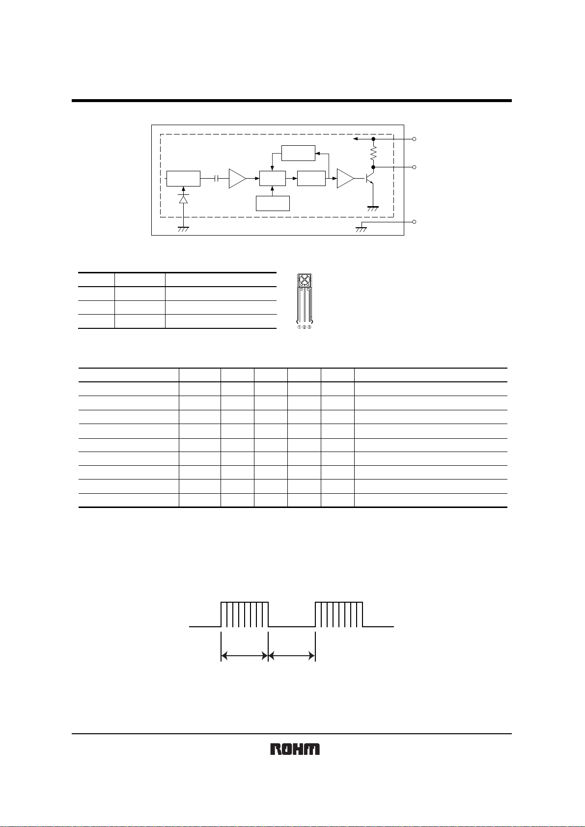
Photo Link Module
zBlock diagram
I / V
AMP
BPF
amplitude
control
Detecter
V
CC
Comparator
RPM6900 series
V
CC
22kΩ
R
OUT
PD
Built-in electric-magnetic shield
ajustment
circuit
GND
zT ermina l description
Pin namePin No. Function
1
2
3
R
OUT
GND
CC
V
OUTPUT TERMINAL
GROUND
POWER SUPPLY
zElectrical, Optical characteristics (Unless otherwise noted, Ta = 25°C V
Parameter Symbol Min. Typ. Max. Unit Conditions
Consumption Current I
Effective Distance
High Level Output Voltage
Low Level Output Voltage
ON Pulse Width
OFF Pulse Width
Center frequency
Horizontal half angle
Vertical half angle
∗1 600/600µs burst wave is transmitted by standard transmitter. However, it must be measured after the initial transmission pulse is 10 pulse.
∗2 It is an angle when the linear arrival distance become 80%.
∗3 RPM6933 33.3kHz RPM6938 37.8kHz
RPM6936 36.0kHz RPM6940 40.0kHz
RPM6937 36.7kHz RPM6957 56.9kHz
CC
L
V
H
L
V
T
ON
T
OFF
fo
θ 80%
θ 80%
−
10
4.5
−
400
400
−
−
−
1.5 mA No outside light, No signal input
2.0
16
−
−
600
0.5
800
600
∗3
35
30
−
−
CC=5V)
m−
Outer light condition Ee < 10 (Ix)
V−
V
µs
µs800
<
Isink 400µA
=
Outer light condition Ee < 10 (Ix) ∗1
Outer light condition Ee < 10 (Ix) ∗1
kHz−
deg
deg
z Measurement Conditions
(1) Transmit signal
∗1
∗1
∗1
∗2
∗2
600µs 600µs
Carrier frequency=fo, Duty=50%
Fig.1 Transmit signal
2/7
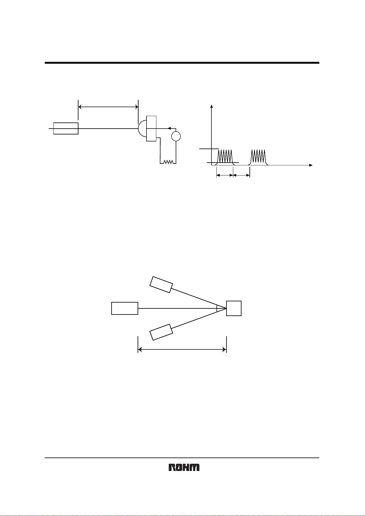
Photo Link Module
(2) Stand ard transmitter
λ peak=940nm
λ ∆=40nm
Lo=20cm
RPM6900 series
Signal scale
i
Carrier frequency fo
Brachy morphic wave duty50%
io
io=5µAp-p
10kΩ
A
ON
io
600µs 600µs
OFF
Standard transmitter
Standard photo-diode
RPM-301B
Fig.2 Measurement of standard transmitter proofreading Fig.3 Standard photo diode current
When standard transmitter output the signal at Fig.1 standard photodiode output become io=5µAp-p (Fig.3) under the
measurement condition Fig.2.
(The radiant intensity of standard transmitter : 50mW / sr)
RPM-301B : standard photodiode has short current Isc=27 µA at E=1000(lx)
(using CIE standard light sou rce A)
(3) Measurement effective distance, horizont al & vertical half angle
RPM6900 series
θ
θ
Standard transmitter
Light detector face
illuminance : Ee
t
Effective distance : L
(θ ; Indicates horizontal and vertical directions)
Fig.4 Measurement condition for effective distance
Effective distance L : Effective distance at θ=0° Fig.4
Horizontal & vertical half angle θ : The angle which effective distance became 50% of L.
3/7

Photo Link Module
(4) Output signal
RPM6900 series
Transmit signal
Output signal
600µs
T
ON
Fig.5
600µs
T
OFF
(5) Measurement circuit for the output voltage and the consumption current
V
CC
Carrier frequency=f
Carrier Duty=50%
V
CC
V
H
CC
1/2 V
V
L
GND
0
I
CC
A
R
OUT
RPM6933
GND
Fig.6
V
H
V
V
L
4/7

RPM6900 series
Photo Link Module
zNotes
(1) All characteristics of th e receiver in this s pecification are s pecified by sup plying burst wave form (Fig. 1) with ROHM
standard transmitter (Fig.2 ).
If in case of other burst wave form w ill be used, p lease check th ese spec. Ca refully under the evaluations.
(2) When the receiver will be used as the w ire-less remote contro ller , please use the signal method the signal fo rmat
which refer to “Measures to prevent malfunctioning of IR remote-controlled electric home appliances”. (Published July
1987 by Association of Electric Home Appliances)
If using other signal method, signal format, (ex: signal format which not including the leader signal) the receiver might
have chances to miss-functio n.
(3) Please set up transmitter’s carrier frequency as same as the receiver’s f
occurred.
(4) If transmission signal has non-continues carrie r , error might be occurred . Continuous carrier is nece ssary.
0 frequency. Otherwise error might be
T1
T1≠T2
T2
(5) The receiver was designed to use as in-door use only.
Therefore, please understand that the receiver cannot cover all characteristics, in case of using it out-door.
(6) Noise environment (Light noise from inverter Lamp, and other kind of Lamps, Power ripple, electromagnetic noise from
power circuit, and etc) may cause a reduced effective distance.
(7) The receiver may not w ork properly if re ceiving signal judgme nt is done by single pul se due to the
surrounding / environmental noises.
To preven t such misjudgment, please ma ke sure that the receiv er is set up to work only when recei ving
series of coded signal.
(8) Emitting unit (remote control transmitter) has to be considered about its emitting device function, characteristics and
characteristics of the receiver.
(9) Do not supply unnecessary stre ss to lead.
(10) Please pay careful attention to the lens.
It might have a chance to miss-function when the lens get dust or dirty. And also please do not touch the lens.
(11) In order to prevent products from ESD, human body and solder iron, etc. are required to be grounded.
5/7

Photo Link Module
zElectrical and optical characteristics curves
0.00
−2.00
120
100
RPM6900 series
80
−4.00
−6.00
Gain : (dB)
−8.00
−10.00
−4 −3 −2 −1fo+1 +2 +3 +4
Frequency : (kHz)
Fig.7 BPF characteristic
100
80
60
40
60
40
20
Rerative sensitivity : (%)
0
700 750 800 850 900 950 1000 1050 1100 1150 1200
Wave length : λ (nm)
Fig.8 Optical bandwidth of the
photo-diode encapsulation
100
80
60
40
20
Relative effective distance : (%)
0
−80 −60 −40 −20 0 20 40 60 80
Angle : (˚)
Fig.9 Direction characteristic
(Horizontal direction)
20
Relative effective distance : (%)
0
−80 −60 −40 −20 0 20 40 60 80
Angle : (˚)
Fig.10 Direction characteristic
(Vertical direction)
6/7

Photo Link Module
zDimensions (Unit : mm)
4.8
3.2
6.0
6.5
4.0
9.0Max.
123
22Min.
2.54
RSIP-A3
2.54
0.8
1.5
0.4
0.5
0.5
6.0
6.5
4.0
9.0Max.
312
2.5
2.542.54
RSIP-A3 V4
RPM6900 series
4.8
3.2
0.8
0.4
1.5
20.0min
Pin No.
Rout
GND
V
CC
7/7

Appendix
Notes
No technical content pages of this document may be reproduced in any form or transmitted by any
means without prior permission of ROHM CO.,LTD.
The contents described herein are subject to change without notice. The specifications for the
product described in this document are for reference only. Upon actual use, therefore, please request
that specifications to be separately delivered.
Application circuit diagrams and circuit constants contained herein are shown as examples of standard
use and operation. Please pay careful attention to the peripheral conditions when designing circuits
and deciding upon circuit constants in the set.
Any data, including, but not limited to application circuit diagrams information, described herein
are intended only as illustrations of such devices and not as the specifications for such devices. ROHM
CO.,LTD. disclaims any warranty that any use of such devices shall be free from infringement of any
third party's intellectual property rights or other proprietary rights, and further, assumes no liability of
whatsoever nature in the event of any such infringement, or arising from or connected with or related
to the use of such devices.
Upon the sale of any such devices, other than for buyer's right to use such devices itself, resell or
otherwise dispose of the same, no express or implied right or license to practice or commercially
exploit any intellectual property rights or other proprietary rights owned or controlled by
ROHM CO., LTD. is granted to any such buyer.
Products listed in this document are no antiradiation design.
The products listed in this document are designed to be used with ordinary electronic equipment or devices
(such as audio visual equipment, office-automation equipment, communications devices, electrical
appliances and electronic toys).
Should you intend to use these products with equipment or devices which require an extremely high level
of reliability and the malfunction of which would directly endanger human life (such as medical
instruments, transportation equipment, aerospace machinery, nuclear-reactor controllers, fuel controllers
and other safety devices), please be sure to consult with our sales representative in advance.
It is our top priority to supply products with the utmost quality and reliability. However, there is always a chance
of failure due to unexpected factors. Therefore, please take into account the derating characteristics and allow
for sufficient safety features, such as extra margin, anti-flammability, and fail-safe measures when designing in
order to prevent possible accidents that may result in bodily harm or fire caused by component failure. ROHM
cannot be held responsible for any damages arising from the use of the products under conditions out of the
range of the specifications or due to non-compliance with the NOTES specified in this catalog.
Thank you for your accessing to ROHM product informations.
More detail product informations and catalogs are available, please contact your nearest sales office.
ROHM Customer Support System
www.rohm.com
THE AMERICAS / EUROPE / ASIA / JAPAN
Contact us : webmaster@ rohm.co. jp
Copyright © 2007 ROHM CO.,LTD.
21, Saiin Mizosaki-cho, Ukyo-ku, Kyoto 615-8585, Japan
TEL : +81-75-311-2121
FAX : +81-75-315-0172
Appendix1-Rev2.0
 Loading...