


查询RCM2228R供应商
RCM2228R-A / B
Liquid Crystal Displays
16 characters × 2 lines COG module
RCM2228R-A / B
The RCM2228R-A / B is a reflective TN type liquid crystal module with a built-in controller / driver LSI and a display
capacity of 16 characters × 2 lines.
zApplic ations
Printers, Copiers, Facsimiles, etc
zFeatures
(1) 5×7 dot character matrix w ith cursor .
(2) Interfaces with 4-bit MPUs.
(3) Displays up to 237 characters and special symbols.
(4) Custom character patterns are displayed with the character RAM.
(5) Abundant instruction set including clear display , cursor on/off, and character blinking.
(6) Compact and lightweight for easy assembly to the host instrument.
(7) Operable on single 5V power supply .
(8) Low power consumption.
zExternal dimensions (Unit : mm) (View ing direction : 6 : 00)
±5°
7.0MAX
0.7±0.7 0.7±0.7
(0.5)
6.0MAX
2
0.7±0.70.7±0.7
1
No.1
50.0±0.3
41.9±0.2
48.0MIN.
(PITCH1.8×9)16.2±0.3
No.10
Over-coating regin
10.0MAX.
24.0MIN.
9.4±0.2 12.3±0.3
6:00
Viewing direction
10.0±0.5
1.5MAX
0.7±0.70.7±0.7
(0.3)
8.7±0.7
Shield tape
0.7±0.7
2.7±0.3
1.1±0.11.1±0.1
±5°
4.0MAX
26.0±0.3
4.350.7
22.0MAX.
25.0MAX.
0.39
0.5
0.05
1.0MAX.
0.3MAX.
9.0MIN.
12.0MIN.
2.0MAX.
4.05±0.3
12.4±0.3
8.0±0.3
(18.0)
2.15 0.5
0.05
Dot de tail
1/7

RCM2228R-A / B
Liquid Crystal Displays
zBlock diagram
V
R
V
RSR
/
W
ED
~
B
4
SEG1~80
V
D
B
7
V
D
S
0
D
S
zPin assignments
Symbol SymbolPin No.
1
2
RS
R / W
3
4
5
DB4
DB5
Pin No.
E
10 V
zPower supply example
COM
9~16
6 DB6
7 DB7
8V
9
LCD MODULE
SS
V
DD
0
V
DD
V
0
V
SS
16character×2lines
VDD−V
0
COM
1~8
DD
V
V
R
VDD−V0 : LCD drive voltage
zAbsolute maximum ratings (Ta=25°C)
Parameter Min.
Power voltage for logics
Power voltage for driving LCD
Input voltage
Operating temperature
Storage temperature
Symbol
V
DD
V
LCD
V
IN
Topr
Tstg
−0.3
−0.3
−0.3
0
−20
Fig.1
VDD+0.3
Max.
6.0
6.0
50
70
Unit
V
V
V
°C
°C
2/7

RCM2228R-A / B
Liquid Crystal Displays
zElectrical characteristics (VDD=5.0V, Ta=25 °C)
Typ.
100
150
3.0
−
−
−
Max.
5.25
5.0
V
0.6
0.2V
1100
1.0
Unit
Conditions
V
V
DD
−
DD
V
V
V
V
RS, R / W, CS
IOH= −0.1mA
IOL=0.1mA
kHz
VDD=5.0V, fosc=270kHz check pattem
Max.
250
250
−
10
−
−
mA
Unit
ms
ms
−
deg
deg
deg
Conditions
φ=0
°,
θ=10
φ=0
°,
θ=10
°,
θ=10
φ=0
>
K 1.4, φ=0
>
K 1.4, θ=10
°
°
°
°
°
Parameter Symbol
Logic power voltage
LCD driving voltage
"H" input voltage
"L" input voltage
"H" output voltage
"L" output voltage
Clock frequency
Current consumption
V
DD
VLCD
VIH
VIL
VOH
VOL
fosc
IDD
zOptical characteristics (Ta=25°C)
When viewing from below
Parameter Symbol
Response time
Response time
Contrast ratio
Viewing angle
Typ.
5.0
−
DD
−
−
V
−
DD
−V
0.7V
VSS
0.75
Min.
4.75
3.0
−0.3
SS
540350
−
0.5
Min.
t
r
t
d
K
θ
1
θ
2
φ
−
−
−
−
40
±
30
(1) Definition θ and φ
θ
Viewing direction
12 o'clock
Y (φ=180°)
Fig.2
(3) Definition of contrast ratio "K"
Selected
100
Brightness (%)
0
Driving voltage
Fig.4
(2) Definition of viewing angles θ1 and θ2
Z (φ=0°)
2'
θ
2
θ
1'
θ
1
XX'
Y' (φ=180°)
Viewing direction 6 o'clock
1.4
Contrast ratio
θ
1
Viewing angle
Fig.3
θ
2
(4) Definition of optical response
K=B
2
/ B
1
B
2
Non-selected
B
1
90%
t
r
Selected condition
100%
Rise time Fall time
Fig.5
10%
t
d
3/7
RCM2228R-A / B
Liquid Crystal Displays
zT ermina l function
Symbol
V
DD
V
SS
0
V
DB4∼DB7
RS
R / W
E
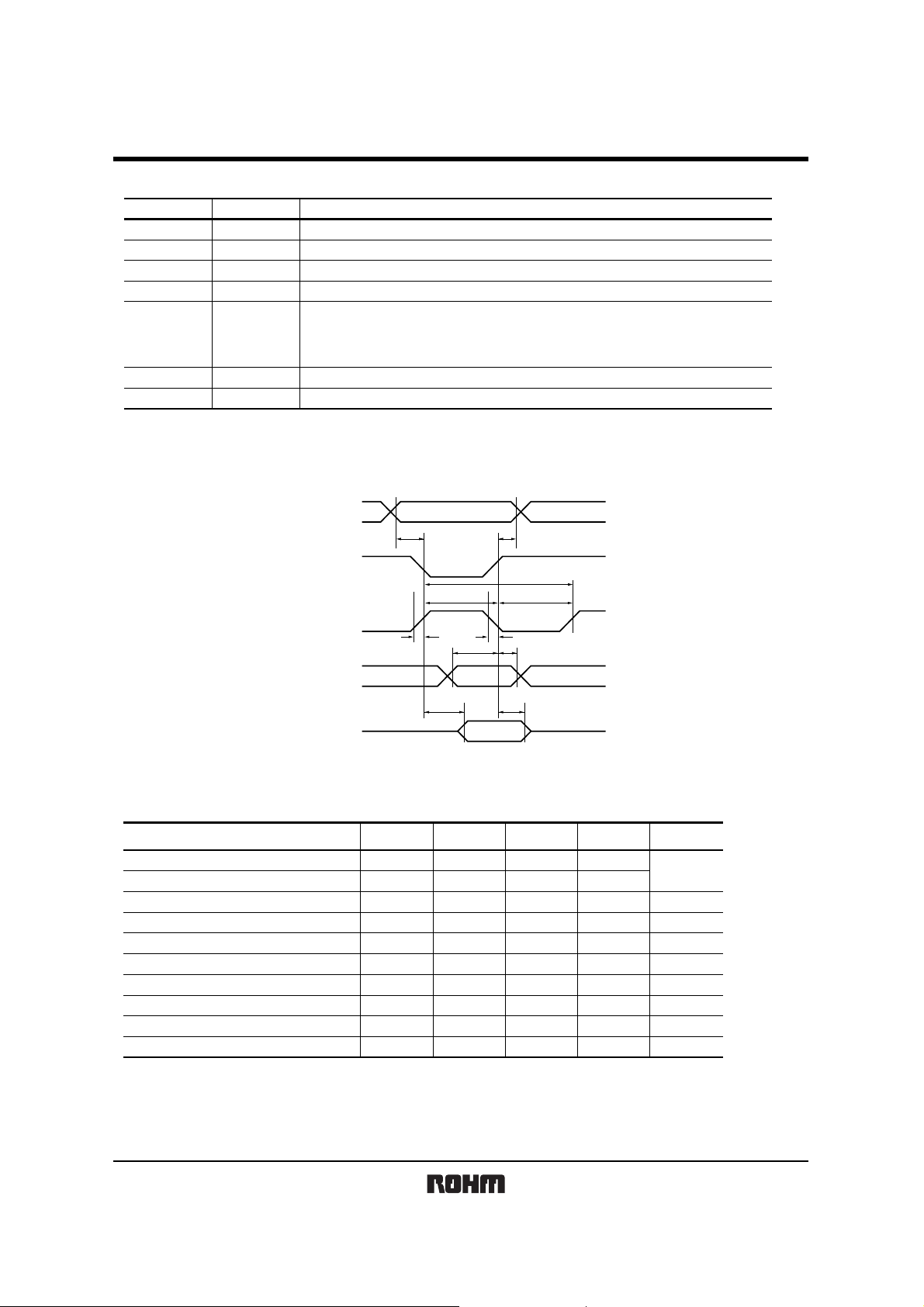
zTiming chart
Writing
I / O Terminal Function
DD
=4.75∼5.25V
Input
Input
Input
Input / Output
V
SS
=0V
V
LCD driving voltage input terminal V
Data bus four-state bi-directional
DD
≥ V0 ≥ V
Register selected signal
Input
L: Instruction register (at write)
L: Busy flag / address counter (at read)
H: Data register (at write & read)
Input
Input
Read / Write select signal L: Write H : Read
Data Read / Write enable signal
RS
R / W
t
AW6
t
AH6
SS
CSB
E
D0 to D7
(Write)
D0 to D7
(Read)
Item
Address hold time
Address set up time
System cycle time
Data setup time
Data hold time
Access time
Output disable time
“E” rise / fall time
“E” pulse width H level
“E” pulse width L level
∗ In designing, please set the timing with sufficient margin
t
CYC6
t
EWH
t
r
t
f
t
DS6tDH6
t
ACC6
Fig.6 interface (Write Operation)
Terminal Min. Max. Unit
RS
RS
RS
D0 to D7
D0 to D7
D0 to D7
D0 to D7
E
E
E
Symbol
AH6
t
tAW6
tCYC6
tDS6
tDH6
tACC6
tOH6
tr, tf
tEWH
tEWL
t
EWL
t
OH6
400
20
−
−
−
−
−
ns
ns
ns
ns
ns
−
ns
ns
−
−
ns
ns
20
20
150
80
20
−
150
−
120
30
4/7
RCM2228R-A / B
Liquid Crystal Displays
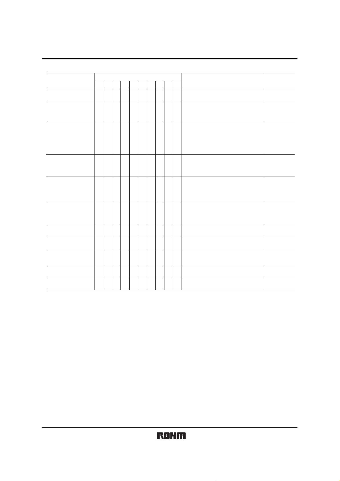
zInstruction
Instruction
Display Clear
Cursor Home
Entry Mode Set 00000001I / DS
Display ON / OFF
Control
Cursor or Display Shift 000001S / CR / L∗∗
Function Set 00001DLN∗∗∗
RW0D70D60D50D40D30D20D11D0
0RS0
000000001∗
0000001DCB
Instruction Code
Description
Clears entire display and sets DDRAM
address 0 in address counter.
Sets DDRAM address 0 in the address
counter Shifted display returns to the
original state.
DDRAM data does not change.
I / D: Specifies cursor / display shift
(I / D=1 : +1 I / D=0 : −1)
S : Executes the shift operation
(S=1: shift S=0 : no shift)
These operations are performed during data
write and read.
D: All display ON / OFF (1: ON , 0: OFF)
C: Cursor ON / OFF (1: ON , 0: OFF)
B: Cursor position blink
ON / OFF (1: ON , 0: OFF)
Shifts the cursor or display without changing
DDRAM data
S / C : (1: Display shift, 0: Cursor shift)
R / L : Specifies the shift direction
(1: Right shift 0: Left shift)
Sets function for the internal operation
DL : (1:8bit , 0:4bit)
N : (1:2line , 0:1line)
Time
(MAX)
1.08ms
1.08ms
26.3µs
26.3µs
26.3µs
26.3µs
CGRAM Address set 0001
DDRAM Address set 001A6
Busy flag
Address counter read
Data write
Data read
Note: Refer to Instruction table for the list of each instruction execution time.
0 1 BF A6
1 0 D7 D6
1 1 D7 D6
A5 A4 A3 A2 A1 A0
A5 A4 A3 A2 A1 A0
A5 A4 A3 A2 A1 A0
D5 D4 D3 D2 D1 D0
D5 D4 D3 D2 D1 D0
Assigns the CGRAM address
Assigns the DDRAM address
BF: Reads the internal operation state
(1: In operation, 0: Completed operation)
AC: Reads the address counter value.
Writes data into DD / CGRAM
Read data from DD / CGRAM
26.3µs
26.3µs
0µs
26.3µs
26.3µs
( ∗ : don't care )
5/7
RCM2228R-A / B
Liquid Crystal Displays
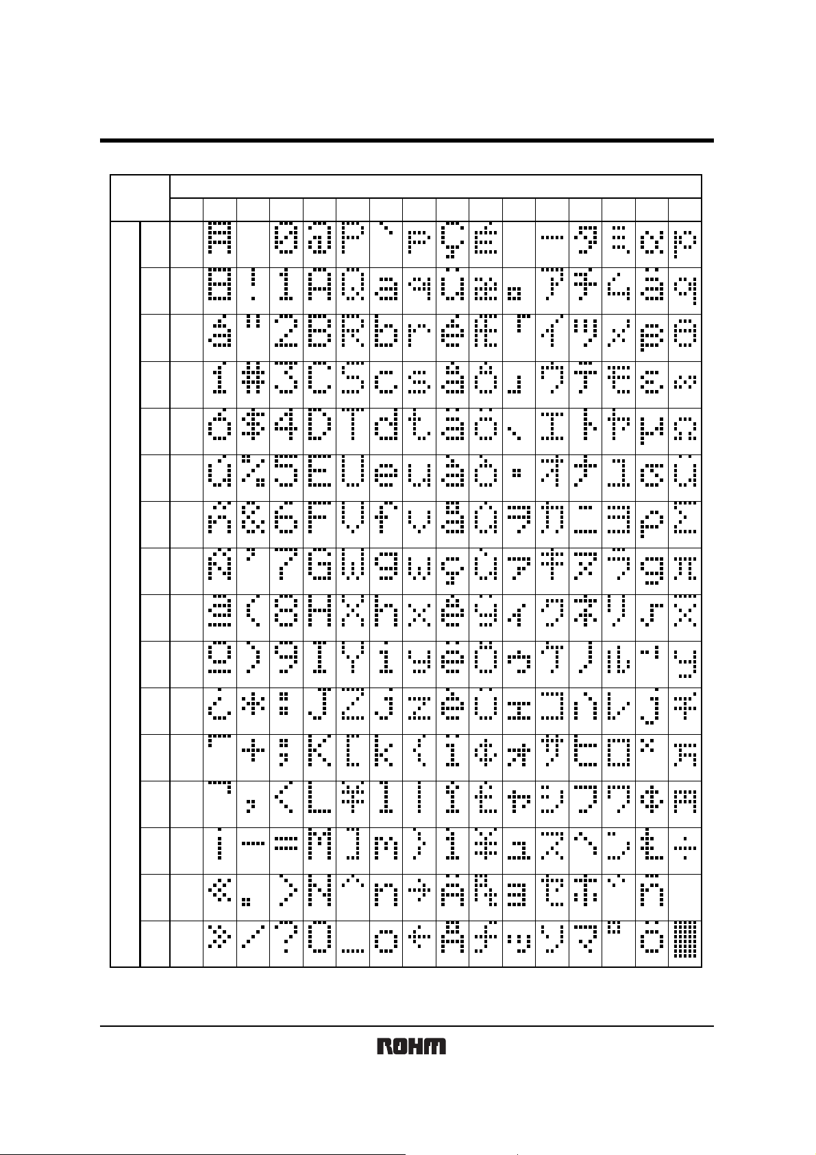
zCharacter code and c orresponding character p attern
UPPER
0000 0001 0010 0011 0100 0101 0110 0111 1000 1001 1010 1011 1100 1101 1110 1111
CGRAM
(1)
0000
0001
(2)
0010
(3)
0011
(4)
0100
(5)
0101
(6)
0110
LOWER
0111
1000
1001
1010
1011
1100
1101
1110
(7)
(8)
(1)
(2)
(3)
(4)
(5)
(6)
(7)
1111
(8)
6/7

RCM2228R-A / B
Liquid Crystal Displays
zOperation note
(1) Handling precautions
• Protect the module from strong shocks as they can cause damage or defective operation.
• The polarizing plate on the surface of the module is soft and can easily be scratched. Wipe aw ay dirt and dust
using an alcohol-based cleanser.
• If the liquid crystal p anel is damaged and the liquid crystal contact s your clothing or body, wash immediately with
soap and water.
• If the module is to be used for long periods subjected to direct sunlight, employ a filter to block the ultravioletrays.
•Do not use the module in areas of high temperature or high humidity. Do not use the module locations exposed to
direct sunlight or fluorescent light.
•A protective film (polyethy lene) is pasted over ROHM li quid crystal modules to protect the p anel surfaces. When
peeling this film off, be sure to peel as slow as possible in order to minimize the generation of static electricity .
(2) Precautions during operation
• Do not connect or disconnect the module w hile the power supply is turned on.
• Input the input signal after the module pow er supply is turned on. When turning if off, turn of f the input signal first.
Otherwise the IC may be damaged by the latch-up phenomenon.
(3) Precautions during installation
• Be sure to use a grounded soldering iron when performing any inst allation procedures.
• Be careful to avoid damage from static electricity. A CMOS-IC is used in the modules circuitry that can be easily
damaged by static electricity.
(4) Precautions during unit assembly
• In order to protect the polarizing plate from dirt or scratches, it is recommended to use a protective cover on the front
surface.
(5) Precautions for COG module
• Do not subject the front and back surface of the IC to light. Doing so may cause defective operation.
• When peeling off the protective film of the panel, use of an ion blow er or other device to reduce the generation of
static electricity is recommended.
• No special measures are taken to prevent the generation of static electricity on the module. Therefore, be sure to
take the appropriate measures to prevent the generation of electrical charge on the LCD module by the design of the
product itself.
7/7
 Loading...