

Page 1
Liquid crystal displays
查询RCM2011M供应商
20 characters2 lines transflective
character module with LED backlight
RCM2011M
The RCM2011M is a transflective TN type liquid crystal module with a yellow-green LED backlight, a built-in controller/driver LSI, and a display capacity of 20 characters 2 lines.
Applications
Personal computers, word processors, facsimiles, telephones, etc.
Features
1) Wide viewing angle and high contrast.
2) 57 dot character matrix with cursor.
3) Interfaces with 4-bit or 8-bit MPUs.
4) Displays up to 226 characters and special symbols.
5) Custom character patterns are displayed with the
character RAM.
6) Abundant instruction set including clear display,
cursor on/off, and character blinking.
7) Compact and light weight for easy assembly to the
host instrument.
8) Operable on single 5 V power supply.
9) Low power consumption.
10) Built-in LED backlight with minimal power consumption.
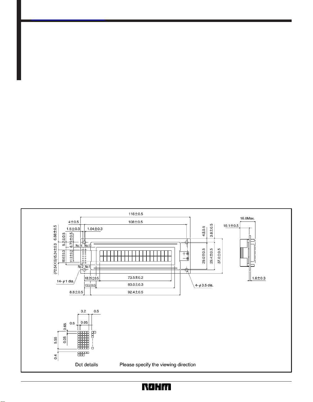
External dimensions (Units: mm)
94
Page 2
Liquid crystal displays RCM2011M
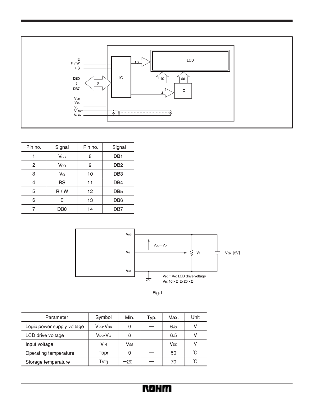
FBlock diagram
FPin assignments
FPower supply example
FAbsolute maximum ratings (Ta = 25_C)
95
Page 3
Liquid crystal displays RCM2011M
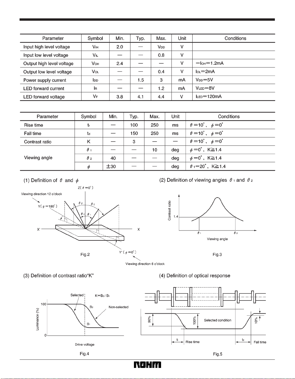
FElectrical characteristics (VDD = 5.0 V ± 0.25 V, Ta = 25_C)
FOptical characteristics (Ta = 25_C) Viewing direction 6 o’clock
96
Page 4
Liquid crystal displays RCM2011M
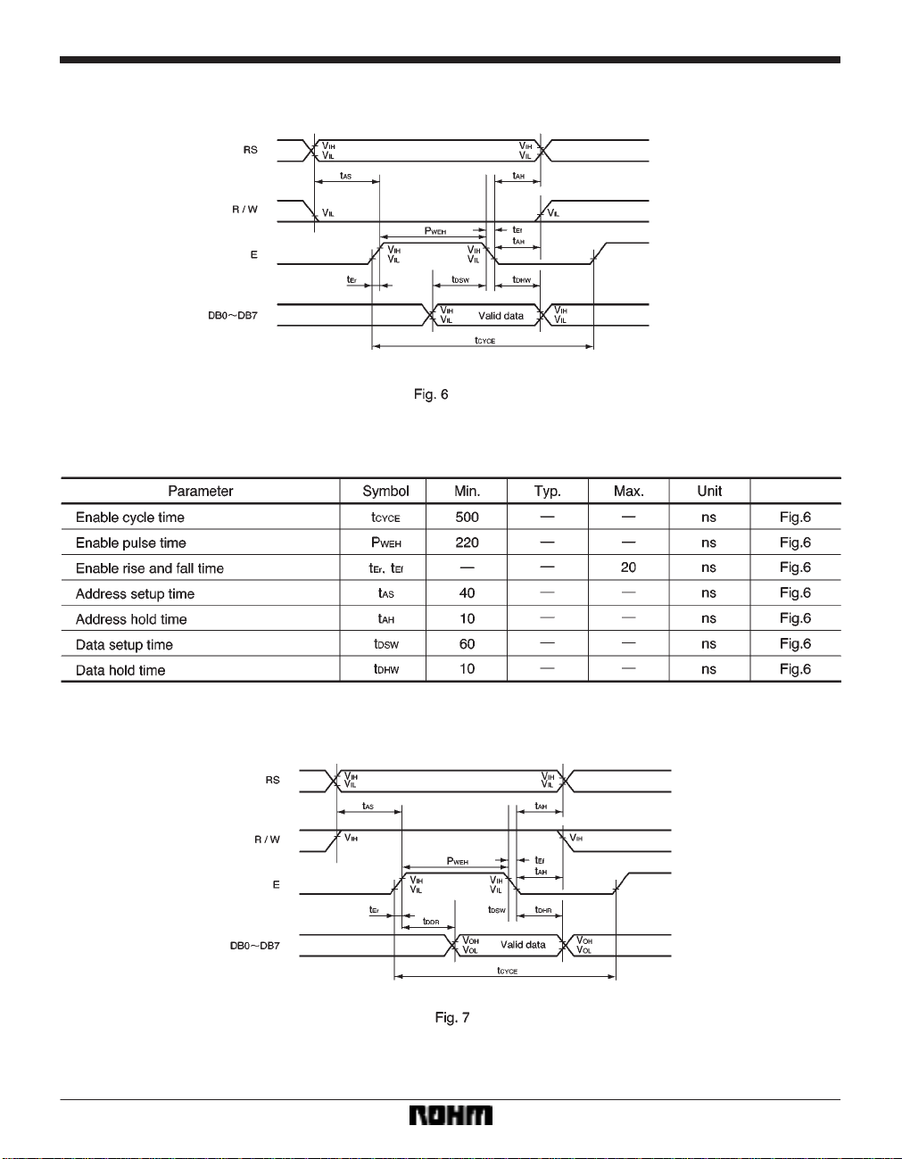
Timing chart
(1) Writing
(2) Reading
97
Page 5

Liquid crystal displays RCM2011M
Pin functions
98
Page 6
Liquid crystal displays RCM2011M
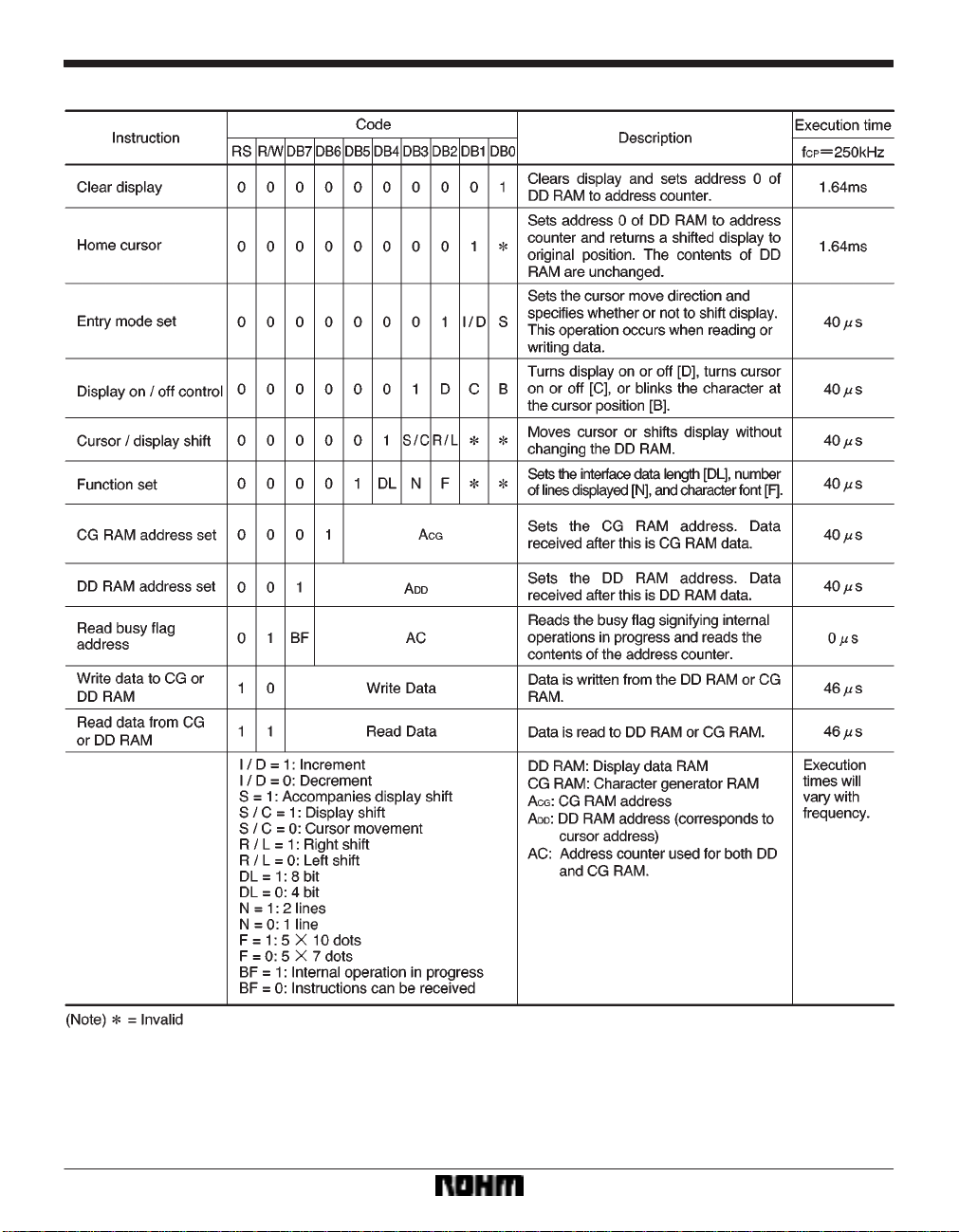
Instructions
99
Page 7

Liquid crystal displays RCM2011M
Character code and corresponding character pattern
100
Page 8

Liquid crystal displays RCM2011M
Reset function
When you turn the power supply on using the internal reset circuit, the module automatically returns to its initial
(reset) settings. At the initial settings, the following
instructions are carried out.
(1) Clear display
The busy flag remains in the busy condition (BF = 1) until
initialization is completed. This takes 15 ms.
(2) Function set
DL = 1: 8-bit interface data length
N = 1
F = 0: 5 7 dot matrix
(3) Display on/off control
D = 0: Display off
C = 0: Cursor off
B = 0: Blinking off
(4) Entry mode set
1/D = 1: +1 (increment)
S = 0: No shift
Depending on the power supply’s rise and fall times when
it is turned on, there may be times when the initialization
cannot be completed. Therefore, be aware of the following timing relationship.
t
OFF regulates the power supply breaks, or on and off
times.
Note) When the above power supply conditions are not met, the internal re-
set circuit will not operate properly.
101
 Loading...