


 Loading...
R&S® FSVA/FSV
Signal and Spectrum Analyzer
Operating Manual
(;ÚÙ:2)
1176.7510.02 ─ 10
Operating Manual
This manual describes the following R&S FSVA/FSV models with firmware version 3.30 and higher:
●R&S®FSVA4 (1321.3008K05)
●R&S®FSVA7 (1321.3008K08)
●R&S®FSVA13 (1321.3008K14)
●R&S®FSVA30 (1321.3008K31)
●R&S®FSVA40 (1321.3008K41)
●R&S®FSV4 (1321.3008K04)
●R&S®FSV7 (1321.3008K07)
●R&S®FSV13 (1321.3008K13)
●R&S®FSV30 (1321.3008K30)
●R&S®FSV40 (1321.3008K39/1321.3008K40)
It also applies to the following R&S®FSV models. However, note the differences described in Chapter 1.2, "Notes for Users of R&S FSV 1307.9002Kxx Models", on page 5.
●R&S®FSV3 (1307.9002K03)
●R&S®FSV7 (1307.9002K07)
●R&S®FSV13 (1307.9002K13)
●R&S®FSV30 (1307.9002K30)
●R&S®FSV40 (1307.9002K39/1307.9002K40)
In addition to the base unit, the following options are described:
●R&S FSV-B9/10 (1310.9545.02/1310.9551.02)
●R&S FSVA-B11 (1321.3714.xx)
●R&S FSV-B17 (1310.9568.02)
●R&S FSV-B21 (1310.9597.02)
●R&S FSV-B22 (1310.9600.02)
●R&S FSV-B24 (1310.9616.13)
●R&S®FSVA-B40 (1329.0214.02) / R&S®FSV-B70 (1310.9645.02)
●R&S FSV-B160 (1311.2015.02/1311.2015.13/1311.2015.40)
●R&S FSV-K9 (1310.8203.02)
●R&S FSV-K14 (1310.8255.02)
© 2017 Rohde & Schwarz GmbH & Co. KG
Mühldorfstr. 15, 81671 München, Germany Phone: +49 89 41 29 - 0
Fax: +49 89 41 29 12 164 Email: info@rohde-schwarz.com
Internet: www.rohde-schwarz.com
Subject to change – Data without tolerance limits is not binding.
R&S® is a registered trademark of Rohde & Schwarz GmbH & Co. KG. Trade names are trademarks of their owners.
Throughout this manual, products from Rohde & Schwarz are indicated without the ® symbol , e.g. R&S®FSV is indicated as R&S FSV.
R&S® FSVA/FSV |
Contents |
|
Contents |
|
1 |
Preface.................................................................................................... |
5 |
1.1 |
For Your Safety............................................................................................................. |
5 |
1.2 |
Notes for Users of R&S FSV 1307.9002Kxx Models.................................................. |
5 |
1.3 |
Conventions Used in the Documentation................................................................... |
6 |
1.4 |
How to Use the Help System........................................................................................ |
7 |
2 |
Documentation Overview...................................................................... |
9 |
2.1 |
Quick Start Guide.......................................................................................................... |
9 |
2.2 |
Operating Manuals and Help........................................................................................ |
9 |
2.3 |
Service Manual.............................................................................................................. |
9 |
2.4 |
Instrument Security Procedures................................................................................ |
10 |
2.5 |
Basic Safety Instructions........................................................................................... |
10 |
2.6 |
Data Sheets and Brochures....................................................................................... |
10 |
2.7 |
Release Notes and Open Source Acknowledgment (OSA)..................................... |
10 |
2.8 |
Application Notes, Application Cards, White Papers, etc....................................... |
10 |
3 |
Quick Start............................................................................................ |
11 |
3.1 |
Front and Rear Panel View......................................................................................... |
11 |
3.2 |
Preparing for Use........................................................................................................ |
23 |
3.3 |
Firmware Update and Installation of Firmware Options.......................................... |
47 |
3.4 |
Basic Operations......................................................................................................... |
49 |
3.5 |
Basic Measurement Examples................................................................................... |
77 |
3.6 |
Advanced Measurement Examples......................................................................... |
105 |
4 |
Instrument Functions........................................................................ |
135 |
4.1 |
General Settings, Printout and Instrument Settings.............................................. |
138 |
4.2 |
Measurement Parameters........................................................................................ |
182 |
4.3 |
Measurement Functions........................................................................................... |
248 |
4.4 |
Measurement Modes................................................................................................. |
405 |
4.5 |
Instrument Functions - I/Q Analyzer....................................................................... |
410 |
4.6Instrument Functions – Tracking Generator (Options R&S FSV-B9/ R&S FSV-B10)
|
.................................................................................................................................... |
444 |
4.7 |
Instrument Functions - R&S Digital I/Q Interface (Option R&S FSV-B17)............ |
469 |
4.8 |
Instrument Functions – External Mixer (Option R&S FSV-B21)........................... |
487 |
Operating Manual 1176.7510.02 ─ 10 |
3 |
R&S® FSVA/FSV |
Contents |
4.9 |
Instrument Functions - Power Sensor (R&S FSV-K9) |
........................................... 508 |
4.10 |
Instrument Functions - Spectrogram Measurements............................................ |
521 |
5 |
Remote Control.................................................................................. |
534 |
5.1 |
Remote Control - Basics.......................................................................................... |
536 |
5.2 |
Controlling the R&S FSVA/FSV Remotely.............................................................. |
574 |
5.3 |
Remote Control – Commands.................................................................................. |
596 |
5.4 |
Remote Control – Programming Examples.......................................................... |
1000 |
6 |
Maintenance..................................................................................... |
1044 |
6.1 |
Cleaning................................................................................................................... |
1044 |
6.2 |
Storing and Packing............................................................................................... |
1045 |
6.3 |
List of Available Power Cables.............................................................................. |
1045 |
7 |
Error Messages................................................................................ |
1046 |
|
List of Commands............................................................................ |
1048 |
|
Index.................................................................................................. |
1065 |
Operating Manual 1176.7510.02 ─ 10 |
4 |
R&S® FSVA/FSV |
Preface |
|
Notes for Users of R&S FSV 1307.9002Kxx Models |
1 Preface
This chapter provides safety-related information, an overview of the user documentation and the conventions used in the documentation.
1.1 For Your Safety
The R&S FSVA/FSV is designated for use in industrial, administrative, and laboratory environments. Use the R&S FSVA/FSV only for its designated purpose. Observe the safety and usage instructions documented in the user manual, as well as operating conditions and performance limits stated in the data sheet.
The product documentation helps you use the R&S FSVA/FSV safely and efficiently. Keep the product documentation in a safe place and pass it on to subsequent users.
Safety information is part of the product documentation. It warns you about potential dangers and gives instructions how to prevent personal injury or damage caused by dangerous situations. Safety information is provided as follows:
●In the "Basic Safety Instructions", safety issues are grouped according to subjects. For example, one subject is electrical safety. The "Basic Safety Instructions" are delivered with the R&S FSVA/FSV in different languages in print.
●Throughout the documentation, safety instructions are provided when you need to take care during setup or operation. Always read the safety instructions carefully. Make sure to comply fully with them. Do not take risks and do not underestimate the potential danger of small details such as a damaged power cable.
1.2Notes for Users of R&S FSV 1307.9002Kxx Models
Users of R&S FSV 1307.9002Kxx models should consider the following differences to the description of the newer R&S FSVA/FSV 1321.3008Kxx models:
●Functions that are based on the Windows 10 operating system (e.g. printing or setting up networks) may have a slightly different appearance or require different settings on the Windows XP based models. For such functions, refer to the Windows documentation or the documentation originally provided with the R&S FSV instrument.
●The R&S FSV 1307.9002K03 model is restricted to a maximum frequency of
3 GHz, whereas the R&S FSVA/FSV1321.3008K04 model has a maximum frequency of 4 GHz.
●The bandwidth extension option R&S FSV-B160 (1311.2015.xx) is not available for the R&S FSV 1307.9002Kxx models. The maximum usable I/Q analysis bandwidth for these models is 28 MHz, or with option R&S FSV-B70, 40 MHz.
Operating Manual 1176.7510.02 ─ 10 |
5 |
R&S® FSVA/FSV |
Preface |
|
Conventions Used in the Documentation |
1.3 Conventions Used in the Documentation
1.3.1 Typographical Conventions
The following text markers are used throughout this documentation:
Convention |
Description |
|
|
"Graphical user interface ele- |
All names of graphical user interface elements on the screen, such as |
ments" |
dialog boxes, menus, options, buttons, and softkeys are enclosed by |
|
quotation marks. |
|
|
KEYS |
Key names are written in capital letters. |
|
|
File names, commands, |
File names, commands, coding samples and screen output are distin- |
program code |
guished by their font. |
Input |
Input to be entered by the user is displayed in italics. |
|
|
Links |
Links that you can click are displayed in blue font. |
|
|
"References" |
References to other parts of the documentation are enclosed by quota- |
|
tion marks. |
|
|
1.3.2 Conventions for Procedure Descriptions
When operating the instrument, several alternative methods may be available to perform the same task. In this case, the procedure using the touchscreen is described. Any elements that can be activated by touching can also be clicked using an additionally connected mouse. The alternative procedure using the keys on the instrument or the on-screen keyboard is only described if it deviates from the standard operating procedures.
The term "select" may refer to any of the described methods, i.e. using a finger on the touchscreen, a mouse pointer in the display, or a key on the instrument or on a keyboard.
1.3.3 Notes on Screenshots
When describing the functions of the product, we use sample screenshots. These screenshots are meant to illustrate as much as possible of the provided functions and possible interdependencies between parameters. The shown values may not represent realistic usage scenarios.
The screenshots usually show a fully equipped product, that is: with all options installed. Thus, some functions shown in the screenshots may not be available in your particular product configuration.
Operating Manual 1176.7510.02 ─ 10 |
6 |

R&S® FSVA/FSV |
Preface |
|
How to Use the Help System |
1.4 How to Use the Help System
Calling context-sensitive and general help
►To display the general help dialog box, press the HELP key on the front panel.
The help dialog box "View" tab is displayed. A topic containing information about the current menu or the currently opened dialog box and its function is displayed.
For standard Windows dialog boxes (e.g. File Properties, Print dialog etc.), no contextsensitive help is available.
►If the help is already displayed, press the softkey for which you want to display help.
A topic containing information about the softkey and its function is displayed.
If a softkey opens a submenu and you press the softkey a second time, the submenu of the softkey is displayed.
Contents of the help dialog box
The help dialog box contains four tabs:
●"Contents" - contains a table of help contents
●"View" - contains a specific help topic
●"Index" - contains index entries to search for help topics
●"Zoom" - contains zoom functions for the help display
To change between these tabs, press the tab on the touchscreen.
Navigating in the table of contents
●To move through the displayed contents entries, use the UP ARROW and DOWN ARROW keys. Entries that contain further entries are marked with a plus sign.
●To display a help topic, press the ENTER key. The "View" tab with the corresponding help topic is displayed.
●To change to the next tab, press the tab on the touchscreen.
Navigating in the help topics
●To scroll through a page, use the rotary knob or the UP ARROW and DOWN ARROW keys.
●To jump to the linked topic, press the link text on the touchscreen.
Searching for a topic
1. Change to the "Index" tab.
Operating Manual 1176.7510.02 ─ 10 |
7 |
R&S® FSVA/FSV |
Preface |
|
How to Use the Help System |
2.Enter the first characters of the topic you are interested in. The entries starting with these characters are displayed.
3.Change the focus by pressing the ENTER key.
4.Select the suitable keyword by using the UP ARROW or DOWN ARROW keys or the rotary knob.
5.Press the ENTER key to display the help topic.
The "View" tab with the corresponding help topic is displayed.
Changing the zoom
1.Change to the "Zoom" tab.
2.Set the zoom using the rotary knob. Four settings are available: 1-4. The smallest size is selected by number 1, the largest size is selected by number 4.
Closing the help window
► Press the ESC key or a function key on the front panel.
Operating Manual 1176.7510.02 ─ 10 |
8 |
R&S® FSVA/FSV |
Documentation Overview |
|
Service Manual |
2 Documentation Overview
This section provides an overview of the R&S FSVA/FSV user documentation. Unless specified otherwise, you find the documents on the R&S FSVA/FSV product page at: www.rohde-schwarz.com/manual/FSVA
2.1 Quick Start Guide
Introduces the R&S FSVA/FSV and describes how to set up and start working with the product. Includes basic operations, typical measurement examples, and general information, e.g. safety instructions, etc. A printed version is delivered with the instrument. A PDF version is available for download on the Internet.
2.2 Operating Manuals and Help
Separate operating manuals are provided for the base unit and the software options:
●Base unit manual
Contains the description of all instrument modes and functions. It also provides an introduction to remote control, a complete description of the remote control commands with programming examples, and information on maintenance, instrument interfaces and error messages. Includes the contents of the getting started manual.
●Software option manual
Contains the description of the specific functions of an option. Basic information on operating the R&S FSVA/FSV is not included.
The contents of the operating manuals are available as help in the R&S FSVA/FSV. The help offers quick, context-sensitive access to the complete information for the base unit and the software options.
All operating manuals are also available for download or for immediate display on the Internet.
2.3 Service Manual
Describes the performance test for checking the rated specifications, module replacement and repair, firmware update, troubleshooting and fault elimination, and contains mechanical drawings and spare part lists.
The service manual is available for registered users on the global Rohde & Schwarz information system (GLORIS, https://gloris.rohde-schwarz.com).
Operating Manual 1176.7510.02 ─ 10 |
9 |
R&S® FSVA/FSV |
Documentation Overview |
|
Application Notes, Application Cards, White Papers, etc. |
2.4 Instrument Security Procedures
Deals with security issues when working with the R&S FSVA/FSV in secure areas. It is available for download on the Internet.
2.5 Basic Safety Instructions
Contains safety instructions, operating conditions and further important information. The printed document is delivered with the instrument.
2.6 Data Sheets and Brochures
The data sheet contains the technical specifications of the R&S FSVA/FSV. It also lists the options and their order numbers as well as optional accessories.
The brochure provides an overview of the instrument and deals with the specific characteristics.
See www.rohde-schwarz.com/brochure-datasheet/FSV
2.7Release Notes and Open Source Acknowledgment (OSA)
The release notes list new features, improvements and known issues of the current firmware version, and describe the firmware installation.
The open source acknowledgment document provides verbatim license texts of the used open source software.
See www.rohde-schwarz.com/firmware/FSV
2.8Application Notes, Application Cards, White Papers, etc.
These documents deal with special applications or background information on particular topics.
See www.rohde-schwarz.com/appnlication/FSV
Operating Manual 1176.7510.02 ─ 10 |
10 |
R&S® FSVA/FSV |
Quick Start |
|
Front and Rear Panel View |
3 Quick Start
Note: the following chapters are identical to those in the printed R&S FSVA/FSV Quick Start Guide.
● Front and Rear Panel View..................................................................................... |
11 |
|
● |
Preparing for Use.................................................................................................... |
23 |
● Firmware Update and Installation of Firmware Options.......................................... |
47 |
|
● |
Basic Operations..................................................................................................... |
49 |
● |
Basic Measurement Examples................................................................................ |
77 |
● |
Advanced Measurement Examples...................................................................... |
105 |
3.1 Front and Rear Panel View
3.1.1 Front Panel View
This chapter describes the front panel, including all function keys and connectors.
Figure 3-1 shows the front panel view of the R&S FSVA. (The R&S FSV is very similar.) The individual elements are described in more detail in the subsequent sections.
|
|
|
8 |
|
9 |
1 |
|
|
10 |
|
11 |
|
|
|
|
|
|
|
4 |
|
|
13 |
|
|
|
|
12 |
|
|
|
|
|
|
|
|
|
|
|
|
14 |
15 |
2 |
|
|
|
|
|
|
|
16 |
17 |
18 |
19 |
3 |
|
20 |
21 |
|
22 |
|
|
|
|
|
|
5 |
6 |
7 |
|
|
|
Figure 3-1: Front panel view of an R&S FSVA
No. |
Description |
See |
|
|
|
1 |
General device functions e.g. Change |
Chapter 3.1.1.1, "Function Keys on the Front Panel", |
|
mode, Setup, Default Settings, Help. |
on page 12 |
|
|
|
2 |
USB connector for external devices, e.g. |
Chapter 3.1.1.3, "Connectors on the Front Panel", |
|
keyboard, mouse |
on page 16 |
|
|
|
Operating Manual 1176.7510.02 ─ 10 |
11 |
R&S® FSVA/FSV |
|
Quick Start |
|
|
|
|
Front and Rear Panel View |
|
|
|
|
|
No. |
Description |
See |
|
|
|
|
|
3 |
ON/OFF switch |
Chapter 3.2.1.8, "Switching the Instrument On and Off", |
|
|
|
on page 32 |
|
|
|
|
|
4 |
Touchscreen; display area for measure- |
Chapter 3.1.1.2, "Touchscreen Display", on page 15 |
|
|
ment results |
|
|
|
|
|
|
5 |
Auxiliary functions to display Windows |
Chapter 3.1.1.1, "Function Keys on the Front Panel", |
|
|
Start menu or on-screen keyboard |
on page 12 |
|
|
|
|
|
6 |
Display options for screen |
Chapter 3.4.4, "Changing the Display", on page 70 |
|
|
|
|
|
7 |
Navigation options for screen menu |
Chapter 3.4.2.6, "Arrow Keys, UNDO/REDO Keys", |
|
|
|
on page 61 |
|
|
|
|
|
8 |
Measurement control settings, e.g. fre- |
Chapter 3.1.1.1, "Function Keys on the Front Panel", |
|
|
quency, levels |
on page 12 |
|
|
|
|
|
9 |
Marker functions |
Chapter 3.1.1.1, "Function Keys on the Front Panel", |
|
|
|
on page 12 |
|
|
|
|
|
10 |
Measurement configuration |
Chapter 3.1.1.1, "Function Keys on the Front Panel", |
|
|
|
on page 12 |
|
|
|
|
|
11 |
Measurement start |
Chapter 3.1.1.1, "Function Keys on the Front Panel", |
|
|
|
on page 12 |
|
|
|
|
|
12 |
Numeric keyboard, units and data entry |
Chapter 3.4.2.4, "Keypad", on page 59 |
|
|
keys |
|
|
|
|
|
|
13 |
Rotary knob |
Chapter 3.4.2.5, "Rotary Knob", on page 61 |
|
|
|
|
|
14 |
Arrow keys |
Chapter 3.4.2.6, "Arrow Keys, UNDO/REDO Keys", |
|
|
|
on page 61 |
|
|
|
|
|
15 |
Undo/redo functions |
Chapter 3.4.2.6, "Arrow Keys, UNDO/REDO Keys", |
|
|
|
on page 61 |
|
|
|
|
|
16 |
AF output with volume control, optional |
Chapter 3.1.1.4, "Optional Front Panel Connectors", |
|
|
|
on page 17 |
|
|
|
|
|
17 |
Noise source control |
Chapter 3.1.1.3, "Connectors on the Front Panel", |
|
|
|
on page 16 |
|
|
|
|
|
18 |
Power sensor, optional |
Chapter 3.1.1.4, "Optional Front Panel Connectors", |
|
|
|
on page 17 |
|
|
|
|
|
19 |
Probe power connector - supply voltage |
Chapter 3.1.1.3, "Connectors on the Front Panel", |
|
|
for measurement accessories |
on page 16 |
|
|
|
|
|
20 |
Tracking generator output, optional |
Chapter 3.1.1.4, "Optional Front Panel Connectors", |
|
|
|
on page 17 |
|
|
|
|
|
21 |
External mixer (LO output, IF input), |
Chapter 3.1.1.4, "Optional Front Panel Connectors", |
|
|
optional |
on page 17 |
|
|
|
|
|
22 |
RF input |
Chapter 3.1.1.3, "Connectors on the Front Panel", |
|
|
|
on page 16 |
|
|
|
|
3.1.1.1Function Keys on the Front Panel
A detailed description of the corresponding menus and the other function keys is provided in chapter 6 "Instrument Functions" of the Operating Manual.
Operating Manual 1176.7510.02 ─ 10 |
12 |

R&S® FSVA/FSV |
|
Quick Start |
|
|
|
|
Front and Rear Panel View |
|
Table 3-1: Front panel function keys |
|
|
|
|
|
|
|
Function key |
Assigned functions |
|
|
|
|
|
|
|
Switches the instrument on and off. |
|
|
|
|
|
|
General device functions |
|
|
|
|
|
|
|
PRESET |
Resets the instrument to the default state. |
|
|
|
|
|
|
SAVE/RCL |
Provides the functions for saving/loading instrument settings and for |
|
|
|
managing stored files. |
|
|
|
|
|
|
SETUP |
Provides basic instrument configuration functions, e.g.: |
|
|
|
● Reference frequency (external/internal), noise source |
|
|
|
● Date, time, display configuration |
|
|
|
● |
LAN interface |
|
|
● |
Self-alignment |
|
|
● Firmware update and enabling of options |
|
|
|
● Information about instrument configuration incl. firmware version and |
|
|
|
|
system error messages |
|
|
● Service support functions (self test etc.) |
|
|
|
|
|
|
Customizes the printout, selects and configures the printer. |
||
|
|
|
|
|
HELP |
Displays the Online Help. |
|
|
|
|
|
|
MODE |
Provides the selection between firmware options. |
|
|
|
|
|
|
External functions |
|
|
|
|
|
|
|
|
Displays Windows Start menu. |
|
|
|
|
|
|
|
Toggles the on-screen keyboard display: |
|
|
|
● at the top of the screen |
|
|
|
● at the bottom of the screen |
|
|
|
● |
off |
|
|
|
|
|
Display options |
|
|
|
|
|
|
|
DISPLAY |
Opens a dialog box to switch screen elements on or off. |
|
|
|
|
|
|
|
Switches between maximized and split display of focus area. |
|
|
|
|
|
|
|
Switches focus area between table and diagram. |
|
|
|
|
|
|
Navigation functions |
|
|
|
|
|
|
|
USER |
Allows you to define and use softkeys to load user-specific settings files. |
|
|
|
|
|
|
HOME |
Jumps to the highest softkey menu level of the current firmware option. |
|
|
|
|
|
|
Measurement settings |
|
|
|
|
|
|
|
FREQ |
Sets the center frequency as well as the start and stop frequencies for |
|
|
(CHANNEL) |
the frequency range under consideration. This key is also used to set the |
|
|
frequency offset and the signal track function. |
||
|
|
||
|
|
(CHANNEL for special applications) |
|
|
|
|
|
|
SPAN |
Sets the frequency span to be analyzed. |
|
|
|
|
|
Operating Manual 1176.7510.02 ─ 10 |
13 |
R&S® FSVA/FSV |
|
Quick Start |
|
|
|
|
Front and Rear Panel View |
|
|
|
|
|
Function key |
Assigned functions |
|
|
|
|
|
|
AMPT |
Sets the reference level, the displayed dynamic range, the RF attenua- |
|
|
(SCALE) |
tion and the unit for the level display. |
|
|
Sets the level offset and the input impedance. |
||
|
|
||
|
|
Activates the preamplifier (option RF Preamplifier, R&S FSV-B22). |
|
|
|
(SCALE for special applications) |
|
|
|
|
|
|
AUTO SET |
Enables automatic settings for level, frequency or sweep type mode. |
|
|
|
|
|
|
BW |
Sets the resolution bandwidth and the video bandwidth. |
|
|
|
|
|
|
SWEEP |
Sets the sweep time and the number of measurement points. |
|
|
|
Selects continuous measurement or single measurement. |
|
|
|
|
|
|
TRACE |
Configures the measured data acquisition and the analysis of the mea- |
|
|
|
surement data. |
|
|
|
|
|
|
TRIG |
Sets the trigger mode, the trigger threshold, the trigger delay, and the |
|
|
|
gate configuration in the case of gated sweep. |
|
|
|
|
|
|
Marker functions |
|
|
|
|
|
|
|
MKR |
Sets and positions the absolute and relative measurement markers |
|
|
|
(markers and delta markers). |
|
|
|
|
|
|
PEAK SEARCH |
Performs a peak search for active marker. If no marker is active, normal |
|
|
|
marker 1 is activated and the peak search is performed for it. |
|
|
|
|
|
|
MKR FUNC |
Provides additional analysis functions of the measurement markers: |
|
|
|
● Frequency counter (Sig Count) |
|
|
|
● Fixed reference point for relative measurement markers (Ref Fixed) |
|
|
|
● Noise marker (Noise Meas) |
|
|
|
● |
Phase noise |
|
|
● n dB down function |
|
|
|
● AM/FM audio demodulation (with option R&S FSV-B3) |
|
|
|
● |
Peak list |
|
|
|
|
|
MKR-> |
Used for search functions of the measurement markers (maximum/mini- |
|
|
|
mum of the trace). |
|
|
|
Assigns the marker frequency to the center frequency, and the marker |
|
|
|
level to the reference level. |
|
|
|
Restricts the search area (Search Limits) and characterizes the maxi- |
|
|
|
mum points and minimum points (Peak Excursion). |
|
|
|
|
|
|
Measurement functions |
|
|
|
|
|
|
|
MEAS |
Provides the measurement functions: |
|
|
|
● Measurement of multicarrier adjacent channel power (Ch Power |
|
|
|
|
ACLR) |
|
|
● Carrier to noise spacing (C/N C/No) |
|
|
|
● |
Occupied bandwidth (OBW) |
|
|
● Spectrum emission mask measurement (Spectrum Emission Mask) |
|
|
|
● Spurious emissions (Spurious Emissions) |
|
|
|
● Measurement of time domain power (Time Domain Power) |
|
|
|
● Signal statistics: amplitude probability distribution (APD) and cumu- |
|
|
|
|
lative complementary distribution function (CCDF) |
|
|
● Third-order intercept point (TOI) |
|
|
|
● AM modulation depth (AM Mod Depth) |
|
|
|
|
|
|
MEAS CONFIG |
Used to define measurement configuration. |
|
|
|
|
|
|
LINES |
Configures display lines and limit lines. |
|
|
|
|
|
Operating Manual 1176.7510.02 ─ 10 |
14 |
R&S® FSVA/FSV |
Quick Start |
|
|
|
Front and Rear Panel View |
|
|
|
|
Function key |
Assigned functions |
|
|
|
|
INPUT/OUTPUT |
Displays softkeys for input/output functions. |
|
|
|
|
Measurement start functions |
|
|
|
|
|
RUN SINGLE |
Starts a single new measurement (Single Sweep Mode). |
|
|
|
|
RUN CONT |
Starts a continuous measurement (Continuous Sweep Mode). |
|
|
|
|
Function execution |
|
|
|
|
|
UNDO |
Reverts last operation. |
|
|
|
|
REDO |
Repeats previously reverted operation. |
|
|
|
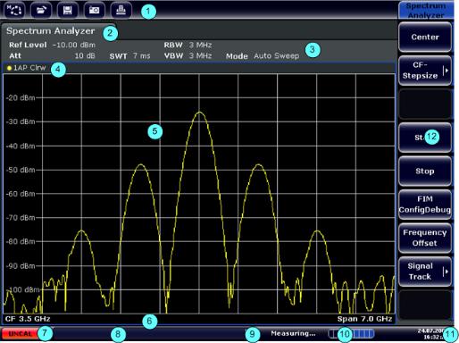
3.1.1.2Touchscreen Display
All measurement results are displayed in the screen on the front panel. Additionally, the screen display provides status and setting information and allows you to switch between various measurement tasks. The screen is touch-sensitive, offering an alternative means of user interaction for quick and easy handling of the device.
The Figure 3-2 shows the touchscreen display of the R&S FSVA/FSV. The individual elements are described in more detail in Chapter 3.4, "Basic Operations",
on page 49.
Figure 3-2: Touchscreen elements
Operating Manual 1176.7510.02 ─ 10 |
15 |

R&S® FSVA/FSV |
Quick Start |
|
Front and Rear Panel View |
1 |
= Toolbar with standard application functions, e.g. print, save/open file etc. |
2 |
= Tabs for individual measurement tasks |
3 |
= Channel information bar for current measurement settings |
4 |
= Diagram header with diagram-specific (trace) information |
5 |
= Measurement results area |
6 |
= Diagram footer with diagram-specific information, depending on measurement mode |
7 |
= Error indicator |
8 |
= Error message, if available |
9 |
= Device status |
10 |
= Progress bar for measurement |
11 |
= Date and time display |
12 |
= Softkeys for menu access |
3.1.1.3Connectors on the Front Panel
This section describes the front connectors and interfaces of the R&S FSVA/FSV. Optional connectors and interfaces are indicated by the option name in brackets. Most connectors on the front panel (except for USB) are located at the bottom right-hand side.
USB
The front panel provides two female USB connectors to connect devices like a keyboard or mouse. Also a memory stick can be connected to store and reload instrument settings and measurement data.
NOISE SOURCE CONTROL
The noise source control female connector is used to provide the supply voltage for an external noise source, e.g., to measure the noise figure and gain of amplifiers and frequency converting DUTs.
Conventional noise sources require a voltage of +28 V in order to be switched on and 0 V to be switched off. The output supports a maximum load of 100 mA.
RF INPUT 50Ω
The RF input is to be connected to the DUT via a cable equipped with an appropriate connector.
Risk of instrument damage
Do not overload the input. For maximum allowed values, see the data sheet.
For AC-coupling, a DC input voltage of 50 V must never be exceeded. For DC-cou- pling, DC voltage must not be applied at the input. In both cases, noncompliance will destroy the input mixers.
PROBE POWER
Operating Manual 1176.7510.02 ─ 10 |
16 |
R&S® FSVA/FSV |
Quick Start |
|
Front and Rear Panel View |
The R&S FSVA/FSV provides a connector for supply voltages of +15 V to -12 V and ground for active probes and preamplifiers. A maximum current of 140 mA is available. This connector is suitable as power supply for high-impedance probes from Agilent.
POWER SENSOR
The LEMOSA female connector is used to connect power sensors of the R&S NRP family (requires option R&S FSVA/FSV-K9). For details on supported power sensors see the data sheet.
3.1.1.4Optional Front Panel Connectors
AF OUTPUT (Audio Demodulator option, R&S FSV-B3)
Headphones equipped with a miniature jack plug can be connected to the AF output female connector. The internal impedance is 10 Ω. The output voltage can be set by using the volume control to the right of the female connector. If a plug is connected, the internal loudspeaker is automatically switched off.
The female connector and volume control are available only with the audio demodulator option (R&S FSV-B3). To use the AF OUTPUT, in the "In-/Output" menu (INPUT/ OUTPUT key), select "Video Output". The output voltage (volume) is 1V.
Risk of hearing damage
Before putting on the headphones, make sure that the volume setting is not too high to protect your hearing.
Tracking Generator Output (GEN OUTPUT 50Ω, Option R&S FSV-B9)
The R&S FSVA/FSV is equipped with an optional tracking generator and therefore provides a tracking generator output connector.
The output of the tracking generator is to be connected to the DUT via a cable equipped with a male N connector. The female connector is available only with the tracking generator option (R&S FSV-B9).
If the output is active, the LED is green.
Risk of damaging the tracking generator
To avoid damaging the tracking generator, make sure that the reverse power (i.e. input power caused, for example, by reflections in the test setup) never exceeds 1 W RF power. Do not apply a DC voltage at the output.
For details, refer to the data sheet.
Operating Manual 1176.7510.02 ─ 10 |
17 |
R&S® FSVA/FSV |
Quick Start |
|
Front and Rear Panel View |
Sensitive DUTs concerning matching
For DUTs with sensitive RF characteristics with regard to matching (VSWR) at the input, insert a 10 dB attenuator between the DUT and the tracking generator.
Connections for External Mixers (EXT MIXER, Option R&S FSV-B21)
External mixers can be connected at the LO OUT/IF IN and IF IN female connectors (option R&S FSV-B21 for R&S FSVA/FSV 30 and R&S FSVA/FSV 40 instruments). Both two-port and three-port mixers can be used. Connect the mixer as follows:
Use the supplied coaxial cable to feed in the LO signal. If no external mixers are connected to the R&S FSVA/FSV, cover the two front connectors LO OUT / IF IN and IF IN with the SMA caps supplied.
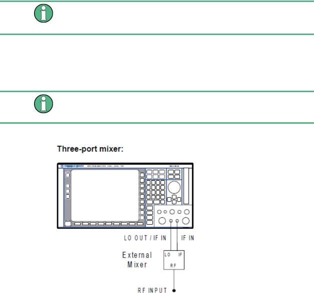
Three-port mixer
1.Connect the LO OUT / IF IN output of the R&S FSVA/FSV to the LO port of the external mixer.
2.Connect the IF IN input of the R&S FSVA/FSV to the IF port of the external mixer.
3.Feed the signal to be measured to the RF input of the external mixer.
Operating Manual 1176.7510.02 ─ 10 |
18 |
R&S® FSVA/FSV |
Quick Start |
|
Front and Rear Panel View |
|
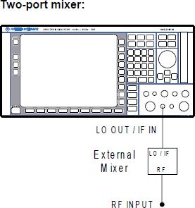
Two-port mixer |
1.1. Connect the LO OUT / IF IN output of the R&S FSVA/FSV to the LO/IF port of the external mixer. The nominal LO level is 15.5 dBm.
Because of the diplexer contained in the R&S FSVA/FSV, the IF signal can be tapped from the line which is used to feed the LO signal to the mixer.
2.Feed the signal to be measured to the RF input of the external mixer.
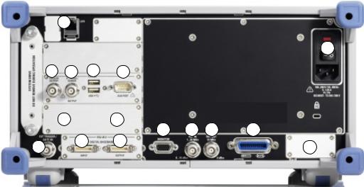
3.1.2Rear Panel View
Figure 3-3 shows the rear panel view of the R&S FSVA/FSV. The individual elements are described in more detail in the subsequent sections. Optional connectors and interfaces are indicated by the option name in brackets.
Operating Manual 1176.7510.02 ─ 10 |
19 |
R&S® FSVA/FSV |
Quick Start |
|
Front and Rear Panel View |
1
15
2 |
3 |
4 |
5 |
67
|
|
11 |
12 |
13 |
14 |
8 |
9 |
10 |
|
|
16 |
|
|
|
|
Figure 3-3: Rear panel view
1= LAN
2 = TRIGGER OUTPUT
3 = IF/VIDEO
4= USB
5= AUX PORT
6+7 = External generator control (option B10)
8= EXT TRIGGER / GATE IN
9+10 = DIGITAL BASEBAND INPUT/OUTPUT connectors (option B17)
11= MONITOR (VGA)
12= REF IN
13= REF OUT
14= GPIB interface
15= AC Power Supply Connection and Main Power Switch with fuse
16= EXT REF with OCXO option (-B4)
3.1.2.1Standard Rear Panel Connectors
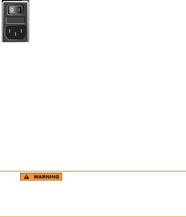
AC Power Supply Connection and Main Power Switch
An AC power supply connector and main power switch are located in a unit on the rear panel of the instrument.
Main power switch function:
Position 1: The instrument is in operation.
Position O: The entire instrument is disconnected from the AC power supply.
For details refer to Chapter 3.2.1.8, "Switching the Instrument On and Off", on page 32.
Operating Manual 1176.7510.02 ─ 10 |
20 |
R&S® FSVA/FSV |
Quick Start |
|
Front and Rear Panel View |
Warm-up time for OCXO
When the instrument is switched on, the OCXO requires an extended warm-up time (see data sheet).
LAN
The LAN interface can be used to connect the R&S FSVA/FSV to a local network for remote control, printouts and data transfer. The assignment of the RJ-45 connector supports twisted-pair category 5 UTP/STP cables in a star configuration (UTP stands for unshielded twisted pair, and STP for shielded twisted pair).
MONITOR (VGA)
The female VGA connector is used to connect an external monitor. Step-by-step instructions how to connect an external monitor are provided in Chapter 3.2.3, "Connecting an External Monitor", on page 35.
EXT TRIGGER / GATE IN
The female connector for external trigger/gate input is used to control the measurement by means of an external signal. The voltage levels can range from 0.5 to 3.5 V. The default value is 1.4 V. The typical input impedance is 10 kΩ.
REF IN
As a reference signal, you can either use the internal reference, or connect an external one. The setup menu is used to switch between the internal and an external reference. The REF IN female connector is used as an input for a 1-20 MHz reference signal. The required input level is 0-10 dBm.
REF OUT
This connector can be used to provide an external reference signal (e.g. the OCXO or ultra high precision reference signal) to other devices that are connected to this instrument. The REF OUT female connector can output a 10 MHz reference signal with an output level of 0 dBm.
GPIB interface
The GPIB interface is in compliance with IEEE488 and SCPI. A computer for remote control can be connected via this interface. To set up the connection, a shielded cable is recommended. For more details refer to chapter 7 "Remote Control Basics" in the Operating Manual.
TRIGGER OUTPUT
The female BNC connector can be used to provide a signal to another device. The signal is TTL compatible (0 V / 5 V). The "Trigger out" softkey in the "In-/Output" menu (INPUT/OUTPUT key) is used to control the trigger output.
IF/VIDEO
The female BNC connector can be used for various outputs:
Operating Manual 1176.7510.02 ─ 10 |
21 |
R&S® FSVA/FSV |
Quick Start |
|
Front and Rear Panel View |
●Intermediate frequency (IF) output of approximately 20 MHz
●Video output (1V)
The "In-/Output" menu (INPUT/OUTPUT key) is used to select between the IF and video output.
USB
The rear panel provides two additional female USB connectors to connect devices like keyboard and mouse. Also, a memory stick can be connected to store and reload instrument settings and measurement data.
EMI impact on measurement results
Electromagnetic interference (EMI) can affect the measurement results. To avoid any impact, make sure that the following conditions are met:
●Use suitable double-shielded cables.
●Do not use USB connecting cables exceeding 1 m in length.
●Use only USB devices that remain within the permissible EMI limits.
●Always terminate any connected IEC-bus cables with an instrument or controller.
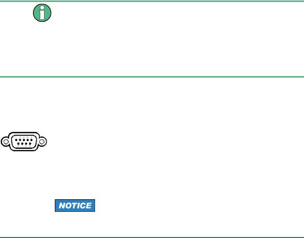
AUX PORT
The 9 pole SUB-D male connector provides control signals for controlling external devices. The voltage levels are of the TTL type (5 V).
|
Pin |
Signal |
Description |
|
|
|
|
|
1 |
+5 V / max. 250 mA |
Supply voltage for external circuits |
|
|
|
|
|
2 to 7 |
I/O |
Control lines for user ports (see User manual) |
|
|
|
|
|
8 |
GND |
Ground |
|
|
|
|
|
9 |
READY FOR TRIGGER |
Signal indicating that the instrument is ready to |
|
|
|
receive a trigger signal (Low active = 0 V) |
|
|
|
|
|
|
|
|
Short-circuit hazard
Always observe the designated pin assignment. A short-circuit can damage the port.
3.1.2.2Optional Rear Panel Connectors
OCXO option (R&S FSV-B4)
This option generates a very precise 10 MHz reference signal with an output level of ≥ 0 dBm. If installed, and if no external signal or ultra high precision reference is used (see "Ultra High Precision Reference Option (R&S FSV-B14)" on page 23), this sig-
Operating Manual 1176.7510.02 ─ 10 |
22 |

R&S® FSVA/FSV |
Quick Start |
|
Preparing for Use |
nal is used as an internal reference. It can also be used to synchronize other connected devices via the REF OUT connector.
Warm-up time for OCXO
When the instrument is switched on, the OCXO requires an extended warm-up time (see data sheet).
Ultra High Precision Reference Option (R&S FSV-B14)
Alternatively to the OCXO reference, an ultra high precision reference (option
R&S FSV-B14) is available. This option generates an even more precise 10 MHz reference signal with an output level of ≥ 0 dBm. If installed, and if no external signal is used, this signal is used as an internal reference (also if an OCXO reference is installed). It can also be used to synchronize other connected devices via the REF OUT connector.
External Generator Control Option (R&S FSV-B10)
The external generator control option provides an additional GPIB and an AUX
CONTROL connector.
The GPIB connector can be used to connect the external generator to the R&S FSVA/ FSV.
The female AUX CONTROL connector is required for TTL synchronization, if supported by the generator.
For details on connecting an external generator see the "External Generator Control" section of the R&S FSVA/FSV User Manual.
Digital Baseband Interface (R&S FSV-B17)
The R&S FSVA/FSV Digital Baseband Interface option (R&S FSV-B17) provides an online digital I/Q data interface on the rear panel of the instrument for input and output. The digital input and output can be enabled in the base unit or in one of the applications (where available).
3.2 Preparing for Use
3.2.1 Putting into Operation
This section describes the basic steps to be taken when setting up the R&S FSVA/FSV for the first time.
Operating Manual 1176.7510.02 ─ 10 |
23 |

R&S® FSVA/FSV |
Quick Start |
|
Preparing for Use |
|
|
Risk of injury due to disregarding safety information
Observe the information on appropriate operating conditions provided in the data sheet to prevent personal injury or damage to the instrument. Read and observe the basic safety instructions provided with the instrument, in addition to the safety instructions in the following sections. In particular:
●Do not open the instrument casing.
Risk of instrument damage due to inappropriate operating conditions
Specific operating conditions are required to ensure accurate measurements and to avoid damage to the instrument. Observe the information on appropriate operating conditions provided in the basic safety instructions and the instrument's data sheet.
Risk of instrument damage due to inappropriate operating conditions
An unsuitable operating site or test setup can damage the instrument and connected devices. Before switching on the instrument, observe the information on appropriate operating conditions provided in the data sheet. In particular, ensure the following:
●All fan openings are unobstructed and the airflow perforations are unimpeded. The minimum distance from the wall is 10 cm.
●The instrument is dry and shows no sign of condensation.
●The instrument is positioned as described in the following sections.
●The ambient temperature does not exceed the range specified in the data sheet.
●Signal levels at the input connectors are all within the specified ranges.
●Signal outputs are connected correctly and are not overloaded.
Instrument damage caused by electrostatic discharge
Electrostatic discharge (ESD) can damage the electronic components of the instrument and the device under test (DUT). Electrostatic discharge is most likely to occur when you connect or disconnect a DUT or test fixture to the instrument's test ports. To prevent electrostatic discharge, use a wrist strap and cord and connect yourself to the ground, or use a conductive floor mat and heel strap combination.
Operating Manual 1176.7510.02 ─ 10 |
24 |
R&S® FSVA/FSV |
Quick Start |
|
Preparing for Use |
EMI impact on measurement results
Electromagnetic interference (EMI) may affect the measurement results.
To suppress generated electromagnetic interference (EMI):
●Use suitable shielded cables of high quality. For example, use double-shielded RF and LAN cables.
●Always terminate open cable ends.
●Note the EMC classification in the data sheet.
3.2.1.1Unpacking and Checking the Instrument
To remove the instrument from its packaging and check the equipment for completeness, proceed as follows:
1.Pull off the polyethylene protection pads from the instrument's rear feet.
2.Carefully remove the pads from the instrument handles at the front.
3.Pull off the corrugated cardboard cover that protects the rear of the instrument.
4.Carefully unthread the corrugated cardboard cover at the front that protects the instrument handles and remove it.
5.Check the equipment for completeness using the delivery note and the accessory lists for the various items.
6.Check the instrument for any damage. If there is damage, immediately contact the carrier who delivered the instrument. Make sure not to discard the box and packing material.
Packing material
Retain the original packing material. If the instrument needs to be transported or shipped later, you can use the material to protect the control elements and connectors.
3.2.1.2Accessory List
The instrument comes with the following accessories:
●Power cable
●Quick Start Guide
3.2.1.3Placing or Mounting the Instrument
The R&S FSVA/FSV is designed for use under laboratory conditions, either on a bench top or in a rack.
Operating Manual 1176.7510.02 ─ 10 |
25 |
R&S® FSVA/FSV |
Quick Start |
|
Preparing for Use |
Bench Top Operation
If the R&S FSVA/FSV is operated on a bench top, the surface should be flat. The instrument can be used in horizontal position, standing on its feet, or with the support feet on the bottom extended.
Risk of injury if feet are folded out
The feet can fold in if they are not folded out completely or if the instrument is shifted. Collapsing feet can cause injury or damage the instrument.
●Fold the feet completely in or out to ensure stability of the instrument. Never shift the instrument when the feet are folded out.
●When the feet are folded out, do not work under the instrument or place anything underneath.
●The feet can break if they are overloaded. The overall load on the folded-out feet must not exceed 500 N.
Operating Manual 1176.7510.02 ─ 10 |
26 |

R&S® FSVA/FSV |
Quick Start |
|
Preparing for Use |
|
|
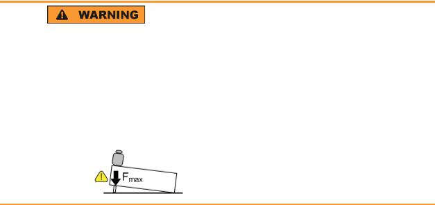
Risk of injury if stacking heavy instruments
A stack of instruments can tilt over and cause injury if not stacked correctly. Furthermore, the instruments at the bottom of the stack can be damaged due to the load imposed by the instruments on top.
Observe the following instructions when stacking instruments:
●Never stack more than three instruments. If you need to stack more than three instruments, install them in a rack.
●The overall load imposed on the lowest instrument must not exceed 500 N.
●It is best if all instruments have the same dimensions (width and length).
If you need to stack smaller instruments on the top, the overall load imposed on the lowest instrument must not exceed 250 N.
●If the instruments have foldable feet, fold them in completely.
Rackmounting
The R&S FSVA/FSV can be installed in a rack using a rack adapter kit (for the order no., see data sheet). The installation instructions are part of the adapter kit.
Risk of instrument damage due to insufficient airflow in a rack
If the instrument is run with insufficient airflow for a longer period, the instrument overheats, which can disturb the operation and even cause damage.
Make sure that all fan openings are unobstructed, that the airflow perforations are unimpeded, and that the minimum distance from the wall is 10 cm.
3.2.1.4Connecting the AC Power
The R&S FSVA/FSV is equipped with an AC power supply connector. The
R&S FSVA/FSV can be used with different AC power voltages and adapts itself auto-
Operating Manual 1176.7510.02 ─ 10 |
27 |
R&S® FSVA/FSV |
Quick Start |
|
Preparing for Use |
matically to it. Refer to the datasheet for the requirements of voltage and frequency. The AC power connector is located on the rear panel of the instrument.
►Connect the R&S FSVA/FSV to the AC power supply using the supplied power cable.
Since the instrument is assembled in line with the specifications for safety class EN61010, it may only be connected to an outlet that has a ground contact.
3.2.1.5Changing the AC Supply Fuse
Only fuses of the type IEC 60 127-T3.15H/250 V should be used. Those fuses are used for all of the specified nominal AC supply voltages.
To change the AC supply fuses
1.Disconnect the power cable.
2.Open the flap covering the fuse holder using a small screwdriver (or similar).
3.Remove the fuse holder.
4.Remove both fuses and install the new ones.
5.Reinsert the fuse holder.
6.Close the flap.
3.2.1.6Using an Optional DC Power Supply
When only DC power is available, for example from a battery or in a vehicle, an optional DC power supply adapter (R&S FSV-B30) can be connected to the R&S FSVA/FSV to operate the instrument with a DC voltage of 10 V to 28 V.
For installation instructions see the option's installation guide.
Shock hazard due to power supply
If you use external power supplies to supply the equipment with DC safety extra low voltage (SELV), make sure the requirements for reinforced or double insulation are met, according to DIN/EN/IEC 61010 (UL61010, CAN CSA C22.2 No. 61010) or DIN/EN/IEC 60950 (UL60950, CAN CSA C22.2 No. 60950). Otherwise you may be injured due to electrical shock.
Before switching on the R&S FSVA/FSV, switch on the DC power supply:
Operating Manual 1176.7510.02 ─ 10 |
28 |
R&S® FSVA/FSV |
Quick Start |
|
Preparing for Use |
Switching the DC power supply on
1.Connect the R&S FSVA/FSV DC power supply device to the DC power source (e.g. battery pack or vehicle) as described in the option's installation guide.
2.Set the switch on the DC power supply to "I". A green LED indicates that the DC power supply is ready for operation.
3.In case of overvoltage or undervoltage, the DC power supply switches off automatically. This state is indicated by means of a red LED.
4.Set the power switch on the rear panel to "I".
5.Press the ON/OFF key on the front panel. A green LED above the ON/OFF key indicates that the instrument is ready for operation.
Switching the DC power supply off
1.Press the ON/OFF key on the front panel of the R&S FSVA/FSV and wait until the instrument has shut down.
2.Switch off the power switch on the rear panel of the R&S FSVA/FSV.
3.Switch off the DC power supply.
3.2.1.7Using an Optional Battery Pack and Charger (Options R&S FSV-B32/-B34)
A lithum-ion battery pack with four rechargeable batteries is available for all
R&S FSVA/FSV instruments (R&S FSV-B32). This battery pack also requires the DC power supply adapter (option R&S FSV-B30, see Chapter 3.2.1.6, "Using an Optional DC Power Supply", on page 28). To charge these batteries, an additional external battery charger is available (option R&S FSV-B34).
For installation instructions see the option's installation guide.
Switching on the battery pack
1.Connect the battery pack to the R&S FSVA/FSV as described in the installation guide.
Note: The batteries must be charged before initial use, see "Charging the Battery Pack" on page 30.
2.Set the switch on the battery pack to "I".
3.Set the switch on the DC power supply to "I". A green LED indicates that the DC power supply is ready for operation.
4.In case of undervoltage, the DC power supply switches off automatically. This state is indicated by means of a red LED.
5.Set the power switch on the rear panel to "I".
6.Press the ON/OFF key on the front panel. A green LED above the ON/OFF key indicates that the instrument is ready for operation.
Operating Manual 1176.7510.02 ─ 10 |
29 |
R&S® FSVA/FSV |
Quick Start |
|
Preparing for Use |
Switching off the battery pack
1.Press the ON/OFF key on the front panel of the R&S FSVA/FSV and wait until the instrument has shut down.
2.Switch off the power switch on the rear panel of the R&S FSVA/FSV.
3.Switch off the DC power supply.
4.Switch off the battery pack.
Charging the Battery Pack
The battery pack is not charged in the factory. The rechargeable batteries must be charged before they are used for the first time.
The R&S FSVA/FSV B34 charger is a standalone charging device which can be used to charge all four rechargeable batteries of the R&S FSVA/FSV B32 battery pack simultaneously. The rechargeable batteries can be charged at ambient temperatures of 0 °C to +45 °C.
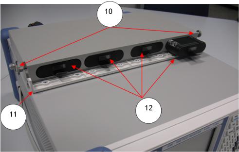
1.Undo the knurled screws (10) on the front of the battery pack and open the flap (11).
2.Pull the rechargeable batteries (12) by the tab out of the housing.
Figure 3-4: Battery compartment
3.Connect the power cable to the charger.
4.Insert the rechargeable batteries into the charging slots of the charger.
Operating Manual 1176.7510.02 ─ 10 |
30 |
Loading...