

®
R&S
ESR
EMI Test Receiver
Getting Started
(=@Ua2)
1316374902
Version 09

This manual describes the following R&S®ESR models with firmware version
3.36 and higher:
●
R&S®ESR3
●
R&S®ESR7
●
R&S®ESR26
© 2021 Rohde & Schwarz GmbH & Co. KG
Mühldorfstr. 15, 81671 München, Germany
Phone: +49 89 41 29 - 0
Email: info@rohde-schwarz.com
Internet: www.rohde-schwarz.com
Subject to change – data without tolerance limits is not binding.
R&S® is a registered trademark of Rohde & Schwarz GmbH & Co. KG.
Trade names are trademarks of the owners.
1316.3749.02 | Version 09 | R&S®ESR
Throughout this manual, products from Rohde & Schwarz are indicated without the ® symbol , e.g.
R&S®ESR is indicated as R&S ESR.

R&S®ESR
Contents
1 Safety and Regulatory Information...................................... 5
1.1 Safety Instructions................................................................................5
1.2 Warning Messages in the Documentation........................................10
1.3 Korea certification class A................................................................. 11
2 Documentation Overview....................................................12
2.1 Getting Started Manual.......................................................................12
2.2 User Manuals and Help...................................................................... 12
2.3 Service Manual....................................................................................13
Contents
2.4 Instrument Security Procedures....................................................... 13
2.5 Basic Safety Instructions................................................................... 13
2.6 Data Sheets and Brochures............................................................... 13
2.7 Release Notes and Open Source Acknowledgment (OSA).............14
2.8 Application Notes, Application Cards, White Papers, etc...............14
3 Conventions Used in the Documentation......................... 15
3.1 Typographical Conventions...............................................................15
3.2 Conventions for Procedure Descriptions.........................................15
3.3 Notes on Screenshots........................................................................ 16
4 Instrument Tour................................................................... 17
4.1 The Front Panel...................................................................................17
4.2 Rear Panel View.................................................................................. 24
5 Preparing For Use................................................................29
5.1 Lifting and Carrying............................................................................29
5.2 Unpacking and Checking................................................................... 29
5.3 Choosing the Operating Site............................................................. 30
3Getting Started 1316.3749.02 ─ 09

R&S®ESR
5.4 Setting up the R&S ESR..................................................................... 30
5.5 Placing the R&S ESR on a Bench Top.............................................. 31
5.6 Mounting the R&S ESR in a Rack......................................................32
5.7 Connecting the AC Power..................................................................32
5.8 Connecting to a DC Power Source (Optional)..................................33
5.9 Switching the Instrument On and Off............................................... 34
5.10 Connecting to LAN............................................................................. 35
5.11 Connecting a Keyboard......................................................................37
5.12 Connecting an External Monitor........................................................37
5.13 Windows Operating System...............................................................38
5.14 Logging On..........................................................................................40
Contents
5.15 Checking the Supplied Options.........................................................42
5.16 Performing a Self Alignment and a Self Test....................................42
5.17 Considerations for Test Setup...........................................................43
6 Basic Operations................................................................. 45
6.1 Information in the Diagram Area....................................................... 45
6.2 Means of User Interaction.................................................................. 53
6.3 Setting Parameters............................................................................. 63
6.4 Changing the Display......................................................................... 69
7 Basic Measurement Examples........................................... 79
7.1 Measuring a Sinusoidal Signal.......................................................... 79
7.2 Measuring Harmonics of Sinusoidal Signals................................... 84
7.3 Measuring Signal Spectra with Multiple Signals............................. 88
7.4 Measurements in Zero Span.............................................................. 95
7.5 Storing and Loading Instrument Settings...................................... 107
Index....................................................................................110
4Getting Started 1316.3749.02 ─ 09

R&S®ESR
Safety and Regulatory Information
Safety Instructions
1 Safety and Regulatory Information
The product documentation helps you use the product safely and efficiently. Follow the instructions provided here and in the following chapters.
Intended use
The product is intended for the development, production and verification of electronic components and devices in industrial, administrative, and laboratory environments. Use the product only for its designated purpose. Observe the operating
conditions and performance limits stated in the data sheet.
Where do I find safety information?
Safety information is part of the product documentation. It warns you of potential
dangers and gives instructions on how to prevent personal injury or damage
caused by dangerous situations. Safety information is provided as follows:
●
In Chapter 1.1, "Safety Instructions", on page 5. The same information is
provided in many languages as printed "Safety Instructions". The printed
"Safety Instructions" are delivered with the product.
●
Throughout the documentation, safety instructions are provided when you
need to take care during setup or operation.
1.1 Safety Instructions
Products from the Rohde & Schwarz group of companies are manufactured
according to the highest technical standards. To use the products safely, follow
the instructions provided here and in the product documentation. Keep the product documentation nearby and offer it to other users.
Use the product only for its intended use and within its performance limits. Intended use and limits are described in the product documentation such as the data
sheet, manuals and the printed "Safety Instructions". If you are unsure about the
appropriate use, contact Rohde & Schwarz customer service.
Using the product requires specialists or specially trained personnel. These users
also need sound knowledge of at least one of the languages in which the user
interfaces and the product documentation are available.
5Getting Started 1316.3749.02 ─ 09

R&S®ESR
Never open the casing of the product. Only service personnel authorized by
Rohde & Schwarz are allowed to repair the product. If any part of the product is
damaged or broken, stop using the product. Contact Rohde & Schwarz customer
service at http://www.customersupport.rohde-schwarz.com.
Lifting and carrying the product
The maximum weight of the product is provided in the data sheet. To move the
product safely, you can use lifting or transporting equipment such as lift trucks
and forklifts. Follow the instructions provided by the equipment manufacturer.
The product is heavy. Do not move or carry the product by yourself. A single person can only carry a maximum of 18 kg safely depending on age, gender and
physical condition. Look up the maximum weight in the data sheet. Use the product handles to move or carry the product. Do not lift by the accessories mounted
on the product. Accessories are not designed to carry the weight of the product.
Safety and Regulatory Information
Safety Instructions
To move the product safely, you can use lifting or transporting equipment such as
lift trucks and forklifts. Follow the instructions provided by the equipment manufacturer.
Choosing the operating site
Only use the product indoors. The product casing is not waterproof. Water that
enters can electrically connect the casing with live parts, which can lead to electric shock, serious personal injury or death if you touch the casing. If
Rohde & Schwarz provides accessories designed for your product, e.g. a carrying
bag, you can use the product outdoors.
Unless otherwise specified, you can operate the product up to an altitude of
2000 m above sea level. The product is suitable for pollution degree 2 environments where nonconductive contamination can occur. For more information on
environmental conditions such as ambient temperature and humidity, see the
data sheet.
Setting up the product
Always place the product on a stable, flat and level surface with the bottom of the
product facing down. If the product is designed for different positions, secure the
product so that it cannot fall over.
If the product has foldable feet, always fold the feet completely in or out to ensure
stability. The feet can collapse if they are not folded out completely or if the prod-
6Getting Started 1316.3749.02 ─ 09

R&S®ESR
uct is moved without lifting it. The foldable feet are designed to carry the weight of
the product, but not an extra load.
If stacking is possible, keep in mind that a stack of products can fall over and
cause injury.
If you mount products in a rack, ensure that the rack has sufficient load capacity
and stability. Observe the specifications of the rack manufacturer. Always install
the products from the bottom shelf to the top shelf so that the rack stands
securely. Secure the product so that it cannot fall off the rack.
Connecting to power
The product is an overvoltage category II product. Connect the product to a fixed
installation used to supply energy-consuming equipment such as household
appliances and similar loads. Keep in mind that electrically powered products
have risks, such as electric shock, fire, personal injury or even death.
Safety and Regulatory Information
Safety Instructions
Take the following measures for your safety:
●
Before switching on the product, ensure that the voltage and frequency indicated on the product match the available power source. If the power adapter
does not adjust automatically, set the correct value and check the rating of the
fuse.
●
If a product has an exchangeable fuse, its type and characteristics are indicated next to the fuse holder. Before changing the fuse, switch off the instrument
and disconnect it from the power source. How to change the fuse is described
in the product documentation.
●
Only use the power cable delivered with the product. It complies with countryspecific safety requirements. Only insert the plug into an outlet with protective
conductor terminal.
●
Only use intact cables and route them carefully so that they cannot be damaged. Check the power cables regularly to ensure that they are undamaged.
Also ensure that nobody can trip over loose cables.
●
If the product needs an external power supply, use the power supply that is
delivered with the product or that is recommended in the product documentation or a power supply that conforms to the country-specific regulations.
●
Only connect the product to a power source with a fuse protection of maximum 20 A.
●
Ensure that you can disconnect the product from the power source at any
time. Pull the power plug to disconnect the product. The power plug must be
easily accessible. If the product is integrated into a system that does not meet
7Getting Started 1316.3749.02 ─ 09

R&S®ESR
these requirements, provide an easily accessible circuit breaker at the system
level.
Using laser products
Lasers are classified according to their potential risk. If exposure to the laser
beam is possible, the product is labeled as shown in the table explaining the
safety labels.
Class 1M lasers
Safe for the naked eye. If you look into the laser beam with optical instruments
such as binoculars or eye loupes, you risk damaging your eyes.
Class 2 lasers
If you stare into the beam, you risk damaging your eyes.
Safety and Regulatory Information
Safety Instructions
Handling batteries safely
The product contains exchangeable or built-in lithium polymer or lithium ion cells
or batteries. The use of the word battery in the following always means all types.
Only the battery contents are potentially hazardous. As long as a battery is
undamaged and the seals remain intact, there is no danger.
Impact, shock or heat can cause damage such as dents, punctures and other
deformations. A damaged battery poses a risk of personal injury. Handle a damaged or leaking battery with extreme care. Immediately ventilate the area since
the battery releases harmful gases. If you come into contact with the battery fluid,
immediately remove all contaminated clothing. Irritation can occur if the battery
fluid comes in contact with your skin or eyes. Immediately and thoroughly rinse
your skin or eyes with water and seek medical aid.
For safe handling, follow these rules:
●
Do not short-circuit the battery.
●
Do not mechanically damage the battery. Do not open or disassemble the battery.
●
Do not expose the battery to high temperatures such as open flames, hot surfaces and sunlight.
●
Only use the battery with the designated Rohde & Schwarz product.
8Getting Started 1316.3749.02 ─ 09
R&S®ESR
Safety and Regulatory Information
Safety Instructions
●
Only use the appropriate Rohde & Schwarz charger to charge the batteries. If
the batteries are improperly charged, there is a risk of explosion. For charging
and discharging temperature ranges, see the product documentation.
●
Replace exchangeable batteries only with the same battery type.
●
Store the battery in the product or use the product packaging.
●
Dispose of exchangeable batteries separately from normal household waste
as specified by the local waste disposal agency.
If you disregard these rules, you risk serious personal injury or even death due to
explosion, fire or hazardous chemical substances. The product documentation
provides further details.
If exchangeable batteries or products with built-in batteries are defective, contact
the Rohde & Schwarz customer service. Rohde & Schwarz classifies the severity
of the defect. When returning batteries or Rohde & Schwarz products containing
batteries, use a carrier qualified to transport dangerous goods and notify the carrier of this classification. Follow the carrier’s transport stipulations in line with
IATA-DGR, IMDG-Code, ADR or RID.
Connecting headphones
Take the following measures to prevent hearing damage. Before using headphones, check the volume and reduce it if necessary. If you monitor varying signal levels, take off the headphones and wait until the signal has settled. Then
adjust the volume.
Cleaning the product
Use a dry, lint-free cloth to clean the product. When cleaning, keep in mind that
the casing is not waterproof. Do not use liquid cleaning agents.
Meaning of safety labels
Safety labels on the product warn against potential hazards.
Potential hazard
Read the product documentation to avoid personal injury or product damage.
Heavy product
Be careful when lifting, moving or carrying the product. Carrying the product requires
a sufficient number of persons or transport equipment.
9Getting Started 1316.3749.02 ─ 09
R&S®ESR
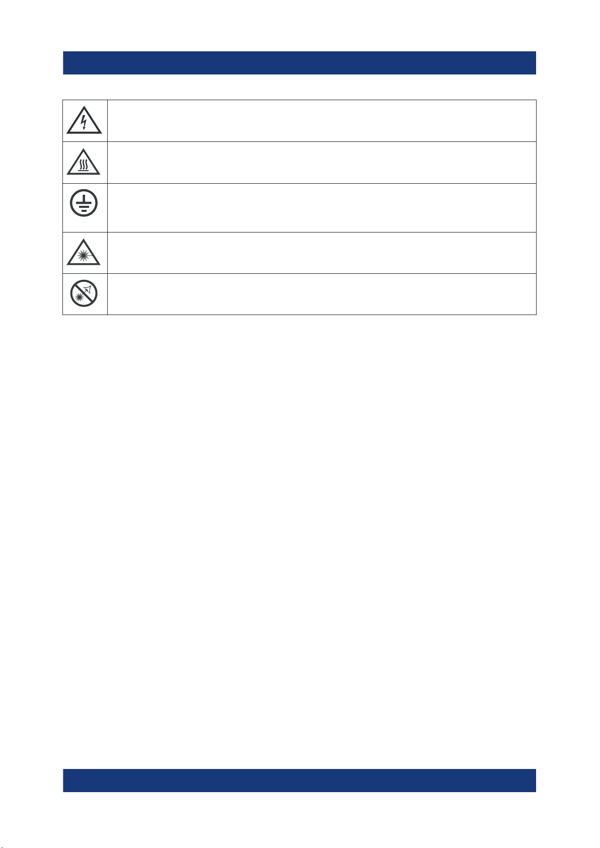
Electrical hazard
Indicates live parts. Risk of electric shock, fire, personal injury or even death.
Hot surface
Do not touch. Risk of skin burns. Risk of fire.
Protective conductor terminal
Connect this terminal to a grounded external conductor or to protective ground. This
connection protects you against electric shock if an electric problem occurs.
Warning: laser beam
The product contains a laser.
Avoid exposure to direct or reflected laser beam.
Safety and Regulatory Information
Warning Messages in the Documentation
1.2 Warning Messages in the Documentation
A warning message points out a risk or danger that you need to be aware of. The
signal word indicates the severity of the safety hazard and how likely it will occur
if you do not follow the safety precautions.
WARNING
Potentially hazardous situation. Could result in death or serious injury if not avoided.
CAUTION
Potentially hazardous situation. Could result in minor or moderate injury if not
avoided.
NOTICE
Potential risks of damage. Could result in damage to the supported product or to
other property.
10Getting Started 1316.3749.02 ─ 09

R&S®ESR
Safety and Regulatory Information
Korea certification class A
1.3 Korea certification class A
이 기기는 업무용(A급) 전자파 적합기기로서 판매자 또는 사용자는 이 점을 주의하
시기 바라며, 가정외의 지역에서 사용하는 것을 목적으로 합니다.
11Getting Started 1316.3749.02 ─ 09

R&S®ESR
Documentation Overview
User Manuals and Help
2 Documentation Overview
This section provides an overview of the R&S ESR user documentation. Unless
specified otherwise, you find the documents on the R&S ESR product page at:
www.rohde-schwarz.com/manual/esr
2.1 Getting Started Manual
Introduces the R&S ESR and describes how to set up and start working with the
product. Includes basic operations, typical measurement examples, and general
information, e.g. safety instructions, etc.
A printed version is delivered with the instrument. A PDF version is available for
download on the Internet.
2.2 User Manuals and Help
Separate user manuals are provided for the base unit and the firmware applications:
●
Base unit manual
Contains the description of all instrument modes and functions. It also provides an introduction to remote control, a complete description of the remote
control commands with programming examples, and information on maintenance, instrument interfaces and error messages. Includes the contents of the
getting started manual.
●
Manuals for (optional) firmware applications
Contains the description of the specific functions of a firmware application,
including remote control commands. Basic information on operating the
R&S ESR is not included.
The contents of the user manuals are available as help in the R&S ESR. The help
offers quick, context-sensitive access to the complete information for the base
unit and the firmware applications.
12Getting Started 1316.3749.02 ─ 09

R&S®ESR
All user manuals are also available for download or for immediate display on the
Internet.
Documentation Overview
Data Sheets and Brochures
2.3 Service Manual
Describes the performance test for checking the rated specifications, module
replacement and repair, firmware update, troubleshooting and fault elimination,
and contains mechanical drawings and spare part lists.
The service manual is available for download for registered users on the global
Rohde & Schwarz information system (GLORIS):
https://gloris.rohde-schwarz.com).
2.4 Instrument Security Procedures
Deals with security issues when working with the R&S ESR in secure areas. It is
available for download on the Internet.
2.5 Basic Safety Instructions
Contains safety instructions, operating conditions and further important information. The printed document is delivered with the instrument.
2.6 Data Sheets and Brochures
The data sheet contains the technical specifications of the R&S ESR. It also lists
the options and their order numbers as well as optional accessories.
The brochure provides an overview of the instrument and deals with the specific
characteristics.
www.rohde-schwarz.com/brochure-datasheet/esr
13Getting Started 1316.3749.02 ─ 09

R&S®ESR
Application Notes, Application Cards, White Papers, etc.
Documentation Overview
2.7 Release Notes and Open Source Acknowledgment (OSA)
The release notes list new features, improvements and known issues of the current firmware version, and describe the firmware installation.
The open source acknowledgment document provides verbatim license texts of
the used open source software.
www.rohde-schwarz.com/firmware/esr
2.8 Application Notes, Application Cards, White Papers, etc.
These documents deal with special applications or background information on
particular topics.
www.rohde-schwarz.com/application/esr
14Getting Started 1316.3749.02 ─ 09
R&S®ESR
Conventions Used in the Documentation
Conventions for Procedure Descriptions
3 Conventions Used in the Documentation
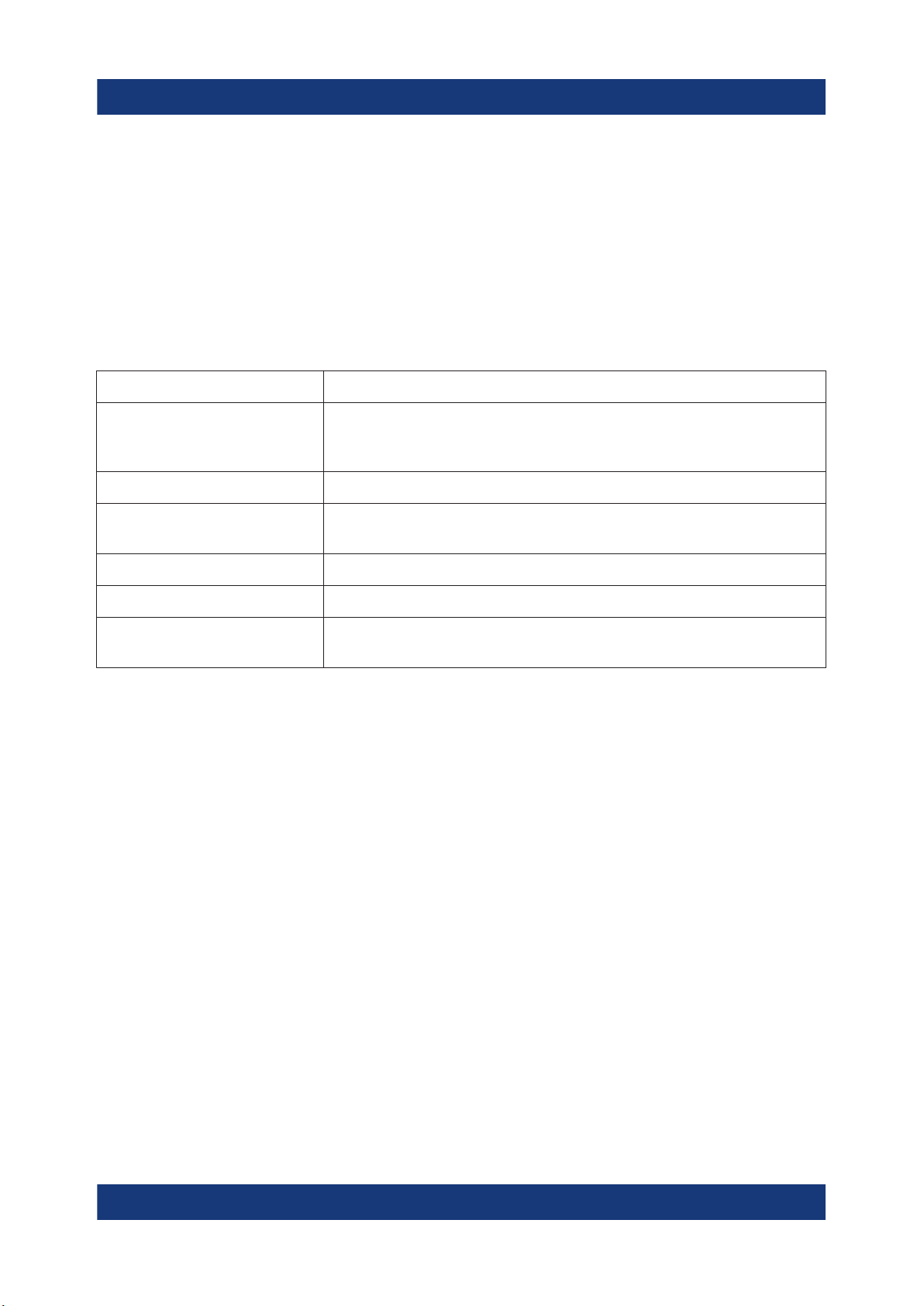
3.1 Typographical Conventions
The following text markers are used throughout this documentation:
Convention Description
"Graphical user interface
elements"
[Keys] Key and knob names are enclosed by square brackets.
Filenames, commands,
program code
Input Input to be entered by the user is displayed in italics.
Links Links that you can click are displayed in blue font.
"References" References to other parts of the documentation are enclosed by
All names of graphical user interface elements on the screen,
such as dialog boxes, menus, options, buttons, and softkeys are
enclosed by quotation marks.
Filenames, commands, coding samples and screen output are
distinguished by their font.
quotation marks.
3.2 Conventions for Procedure Descriptions
When operating the instrument, several alternative methods may be available to
perform the same task. In this case, the procedure using the touchscreen is
described. Any elements that can be activated by touching can also be clicked
using an additionally connected mouse. The alternative procedure using the keys
on the instrument or the on-screen keyboard is only described if it deviates from
the standard operating procedures.
The term "select" may refer to any of the described methods, i.e. using a finger on
the touchscreen, a mouse pointer in the display, or a key on the instrument or on
a keyboard.
15Getting Started 1316.3749.02 ─ 09

R&S®ESR
Conventions Used in the Documentation
Notes on Screenshots
3.3 Notes on Screenshots
When describing the functions of the product, we use sample screenshots. These
screenshots are meant to illustrate as many as possible of the provided functions
and possible interdependencies between parameters. The shown values may not
represent realistic usage scenarios.
The screenshots usually show a fully equipped product, that is: with all options
installed. Thus, some functions shown in the screenshots may not be available in
your particular product configuration.
16Getting Started 1316.3749.02 ─ 09
R&S®ESR
Instrument Tour
The Front Panel
4 Instrument Tour
On the instrument tour, you can learn about the different control elements and
connectors on the front and back panel of the R&S ESR.
4.1 The Front Panel
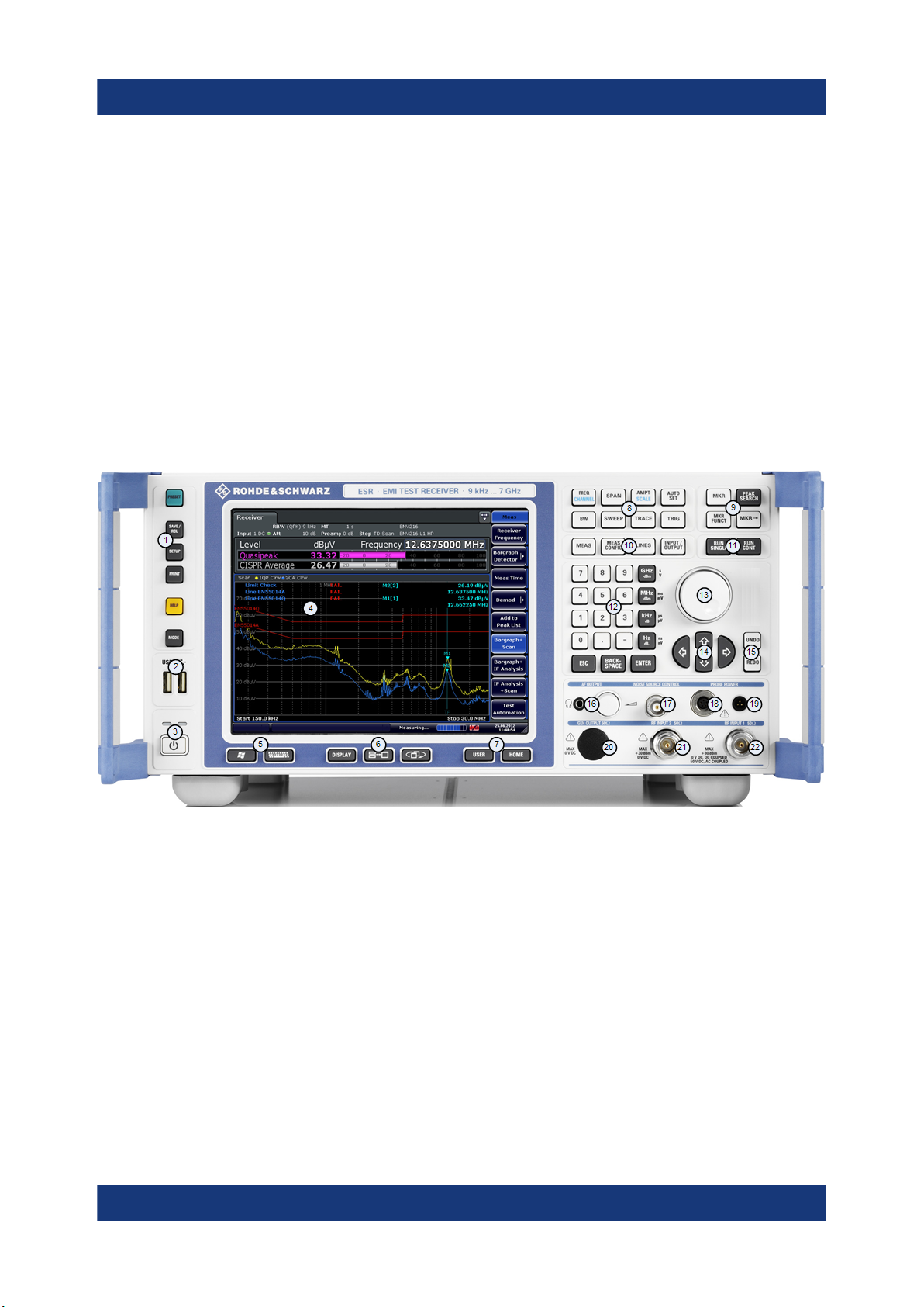
The front panel of the R&S ESR is shown in Figure 4-1. Each element (function
keys and connectors) is described in more detail in the subsequent sections.
Figure 4-1: Front panel of the R&S ESR
1 = Function keys
2 = USB interface
3 = Power button
4 = Display
5 = Access to operating system and online keyboard
6 = Display options
7 = Navigation options for menus
8 = Measurement configuration
9 = Marker functions
10 = Measurement control
11 = Measurement start
12 = Data entry keys
13 = Rotary knob
14 = Navigation keys
15 = Undo / redo function
17Getting Started 1316.3749.02 ─ 09
R&S®ESR
Instrument Tour
The Front Panel
16 = AF output incl. volume control
17 = Noise source control
18 = Supply voltage for accessories
19 = Supply voltage for accessories
20 = Tracking generator output
21 = RF input 2
22 = RF input 1
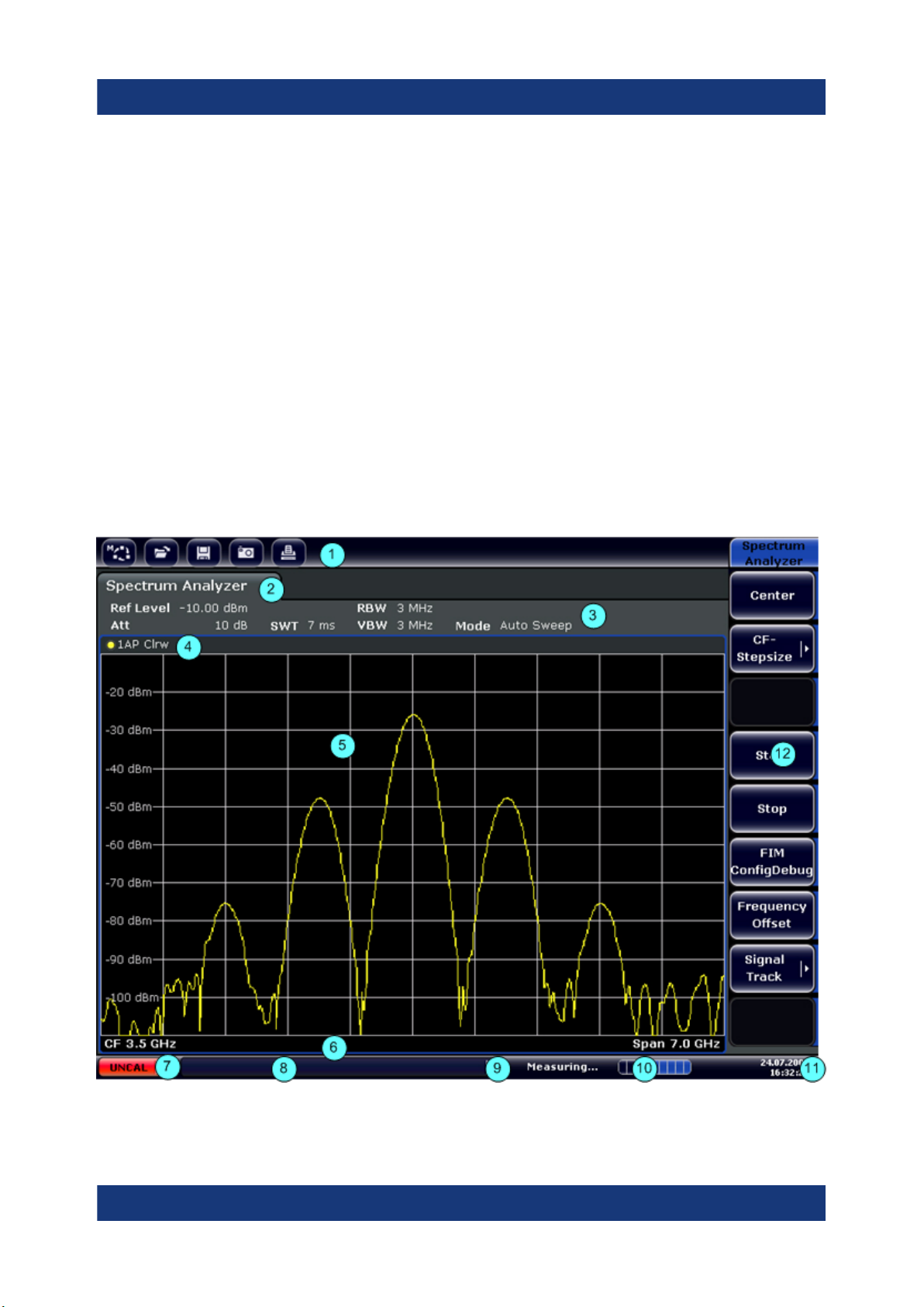
4.1.1 Touchscreen Display
The touchscreen on the front panel of the R&S ESR displays the measurement
results. Additionally, the screen display provides status and setting information
and allows you to switch between various measurement tasks. The screen is
touch-sensitive, offering an alternative means of user interaction for quick and
easy handling of the instrument.
Figure 4-2: Touchscreen elements
18Getting Started 1316.3749.02 ─ 09
R&S®ESR
Instrument Tour
The Front Panel
1 = Toolbar with standard application functions, e.g. print, save/open file etc.
2 = Tabs for individual measurement tasks
3 = Channel information bar for current measurement settings
4 = Diagram header with diagram-specific (trace) information
5 = Measurement results area
6 = Diagram footer with diagram-specific information, depending on measurement mode
7 = Error indicator
8 = Error message, if available
9 = Device status
10 = Progress bar for measurement
11 = Date and time display
12 = Softkeys for menu access
A touchscreen is a screen that is touch-sensitive, i.e. it reacts in a specified way
when a particular element on the screen is tapped by a finger or a pointing
device, for example. Any user interface elements that can be clicked on by a
mouse pointer can also be tapped on the screen to trigger the same behavior,
and vice versa.
Using the touchscreen, the following tasks (among others) can be performed by
the tap of your finger:
●
Changing a setting
●
Changing the display
●
Moving a marker
●
Selecting a new evaluation method
●
Scrolling through a result list
●
Saving or printing results and settings
4.1.2 Function Keys on the Front Panel
A detailed description of the corresponding menus and the other function keys is
provided in chapter 6 "Instrument Functions" of the Operating Manual.
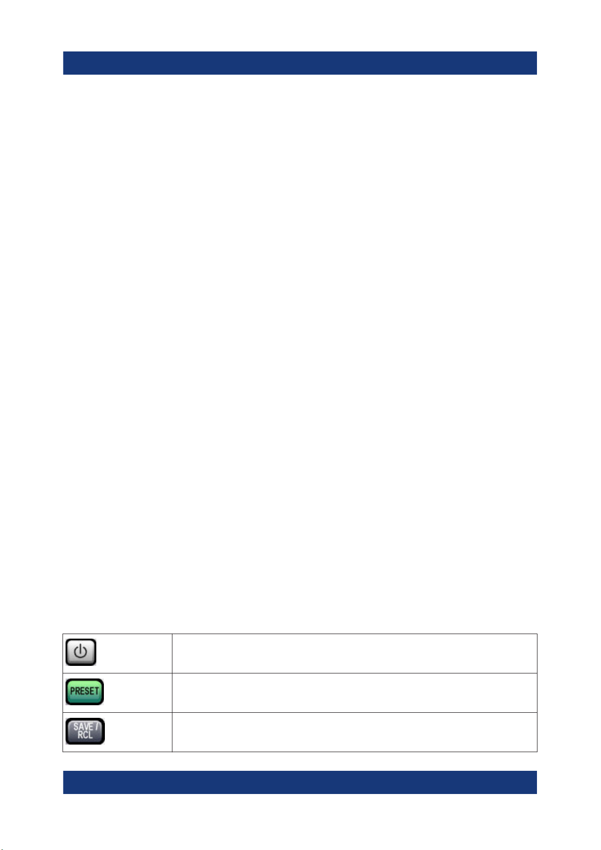
Table 4-1: Function keys
Turns the instrument on and off.
Restores the default configuration of the R&S ESR.
Provides functionality to save, restore and manage instrument settings
and other files.
19Getting Started 1316.3749.02 ─ 09
R&S®ESR
Instrument Tour
The Front Panel
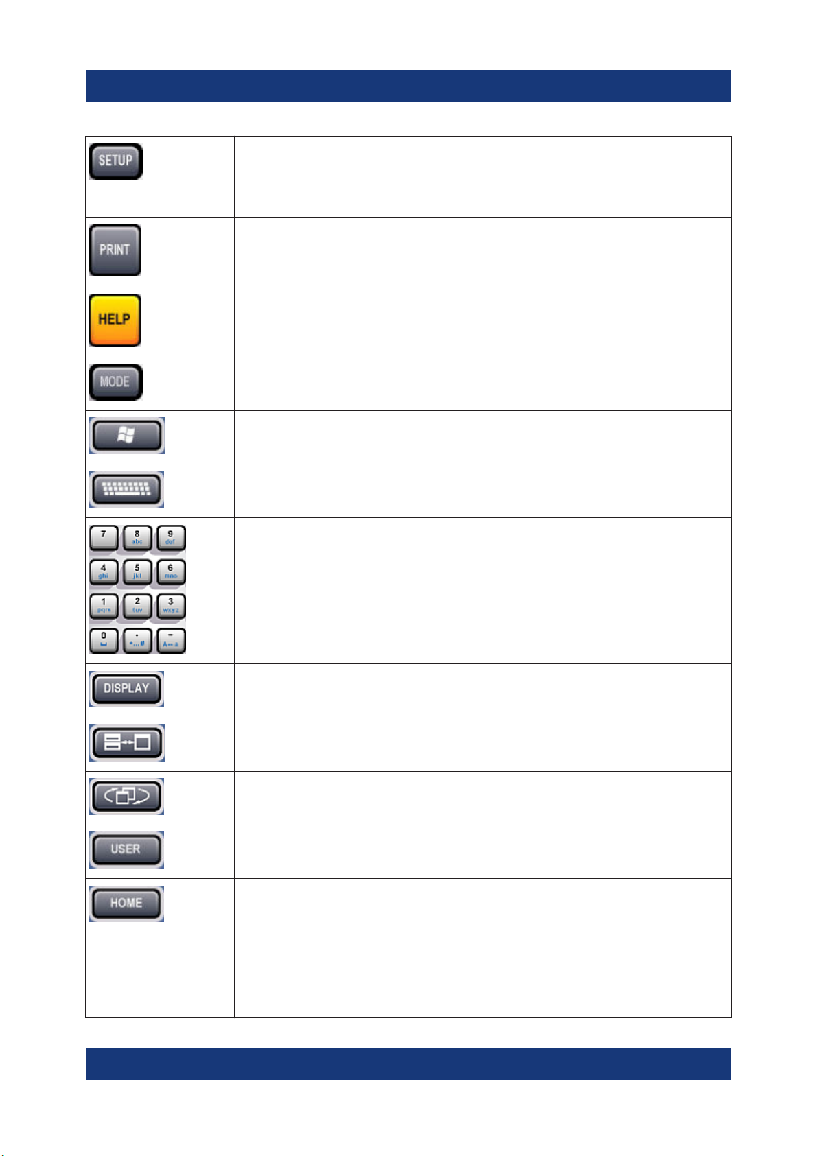
Provides functionality for general instrument configuration, for example:
●
to configure the display
●
to set the date and time
●
to establish a LAN connection
Provides functionality to configure printers and hardcopys.
Displays the online help.
Selects the operating mode or firmware application.
Opens the Windows "Start" menu
Turns the on-screen keyboard on and off. Repeatedly pressing the key
changes the position of the keyboard (top or bottom of the display).
Selects alphanumeric characters.
Opens a dialog box to turn screen elements on or off.
Switches between maximized and split display of focus area.
Switches focus area between table and diagram.
Allows you to define and use softkeys to load custom configurations.
Opens the root menu of the current application.
FREQ (CHANNEL) Provides functionality to define frequency parameters, for example:
●
the center or receiver frequency
●
the frequency offset
(CHANNEL is for special applications)
20Getting Started 1316.3749.02 ─ 09
R&S®ESR
Instrument Tour
The Front Panel
SPAN Provides functionality to configure the frequency span.
In the realtime application, the span is coupled to the RBW and restricted
to 40 MHz.
AMPT (SCALE) Provides functionality to configure amplitude or level characteristics, for
example:
●
the reference level
●
the attenuation
●
the input impedance
●
the scale of the level axis
●
the preamplifier
AUTO SET Provides functionality to automatically define various parameters like the
level or frequency.
BW Provides functionality to define the resolution and video bandwidth.
In the realtime application, the RBW is coupled to the span. Video bandwidth is not available.
SWEEP Provides functionality to configure the sweep, for example:
●
the measurement time
●
the number of measurement points
●
the measurement mode (single or continuous measurements)
In the realtime application, the number of measurement points is a fix
value (801 points).
TRACE Provides functionality to configure data acquisition and analyze mea-
sured data, for example:
●
the trace mode
●
the detector
TRIG Provides functionality to configure triggered and gated measurements,
for example:
MKR Provides functionality to activate and position absolute and relative mark-
ers (markers and delta markers).
PEAK SEARCH Performs a peak search for active markers.
If no marker is active, Marker 1 is activated and the peak search is performed for it.
MKR FUNC Provides additional analysis functions of the measurement markers, for
example:
●
the frequency counter
●
the noise measurement
●
the phase noise measurement
●
the AM/FM audio demodulator
In the realtime application, marker functions are not available.
MKR➙ Provides functionality to position and control markers, for example:
●
to position the marker on the center frequency
●
to define the marker search area
●
to configure the peak excursion
21Getting Started 1316.3749.02 ─ 09
R&S®ESR
MEAS Provides the measurement functions, for example:
●
the bargraph measurement (in Receiver mode)
●
the scan and final measurement (in Receiver mode)
●
the AF demodulation (in Receiver mode)
●
IF analysis (in Receiver mode with option R&S ESR-K56)
●
the realtime spectrum (in Realtime mode)
●
the spectrogram measurement (in Realtime mode)
●
the persistence spectrum (in Realtime mode)
●
the channel power and ACLR measurement (in Spectrum mode)
●
the occupied bandwidth measurement (in Spectrum mode)
●
the Spectrum Emission Mask (SEM) measurement (in spectrum
mode)
●
the spurious emission measurement (in spectrum mode)
●
the signal statistics (in spectrum mode)
MEAS CONFIG Provides functionality to configure the measurement.
LINES Provides functionality to control display and limit lines.
INPUT/OUTPUT Provides functionality to configure inputs and outputs.
Instrument Tour
The Front Panel
RUN SINGLE Starts a single measurement.
RUN CONT Starts a continuous measurement.
UNDO Reverts the last operation.
REDO Repeats previously reverted operation.
4.1.3 USB Interface
The front panel provides two female USB connectors to connect devices like an
external keyboard or mouse. You can also connect a memory stick to save and
restore instrument settings and measurement data.
4.1.4 Noise Source Control
The noise source control female connector is used to provide the supply voltage
for an external noise source, for example to measure the noise figure and gain of
amplifiers and frequency converting DUTs.
Conventional noise sources require a voltage of +28 V in order to be switched on
and 0 V to be switched off. The output supports a maximum load of 100 mA.
22Getting Started 1316.3749.02 ─ 09

R&S®ESR
Instrument Tour
The Front Panel
4.1.5 RF Input 50Ω
The R&S ESR provides two RF inputs for connection of a device under test
(DUT) to the R&S ESR. The DUT is connected to the RF Input via cable and an
approriate connector (for example a male N connector).
The first RF Input supports a frequency range from 9 kHz to f
tion range from 0 dB to 75 dB. The second RF Input supports a frequency range
from 9 kHz to 1 GHz and an attenuation range from 10 dB to 75 dB. Attenuation
levels smaller than 10 dB are not possible at RF Input 2.
With option R&S ESR-B29, the minimum frequency is extended to 10 Hz at both
RF inputs.
and an attenua-
max
4.1.6 Probe Power
The R&S ESR provides two connectors to supply accessories like transducers or
probes with power.
The probe power connector with five pins supports supply voltages of ±10 V and
ground. The maximum permissible current is 200 mA. This probe power connector is suitable, for example, for transducers from Rohde & Schwarz.
The probe power connector with three pins supports supply voltages from +15 V
to -12.6 V and ground. The maximum permissible current is 150 mA. This probe
power connector is suitable, for example, for high-impedance probes from Agilent.
4.1.7 AF Output
Headphones equipped with a miniature jack plug can be connected to the AF output female connector. The internal impedance is 10 Ω. The output voltage can be
set by using the volume control to the right of the female connector. If a plug is
connected, the internal loudspeaker is automatically switched off.
See also "Connecting headphones" on page 9.
4.1.8 Tracking Generator Output (Optional)
The R&S ESR is equipped with an optional tracking generator and therefore provides a tracking generator output connector.
23Getting Started 1316.3749.02 ─ 09
R&S®ESR
Instrument Tour
Rear Panel View
The output of the tracking generator is connected to the DUT via a cable equipped with a male N connector. The female connector is available only with the
tracking generator option (R&S FSV-B9).
Sensitive DUTs concerning matching
For DUTs with sensitive RF characteristics with regard to matching (VSWR)
at the input, insert a 10 dB attenuator between the DUT and the tracking
generator.
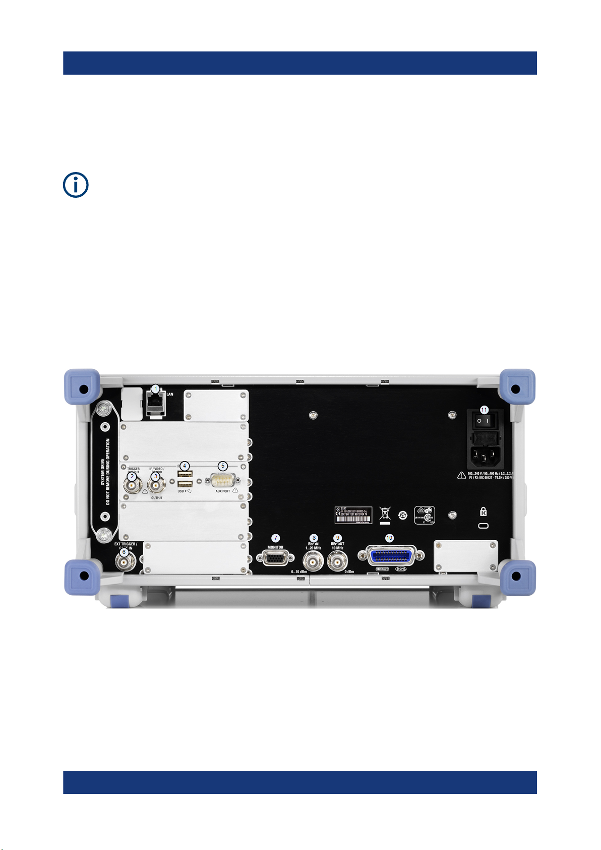
4.2 Rear Panel View
The rear panel of the R&S ESR is shown in Figure 4-3. Each element is described in more detail in the subsequent sections.
Figure 4-3: R&S ESR rear panel
1 = LAN interface
2 = Trigger output
3 = IF / Video connector
4 = USB interface
5 = AUX port
6 = External trigger / gate input
7 = VGA interface
8 = Reference in
24Getting Started 1316.3749.02 ─ 09

R&S®ESR
9 = Reference out
10 = GPIB interface
11 = AC power supply and main switch
Instrument Tour
Rear Panel View
4.2.1 AC Power Supply Connection and Main Power Switch
The AC power supply connector and main power switch are located in a unit on
the rear panel of the instrument.
The main power switch works as follows.
●
Position "I": The instrument is supplied with power and in operation.
The OCXO reference frequency is warmed up.
●
Position "O": The instrument is disconnected from the AC power supply.
For more information see Chapter 5.7, "Connecting the AC Power", on page 32.
4.2.2 LAN
The LAN interface can be used to connect the R&S ESR to a local network for
remote control, printouts and data transfer. The assignment of the RJ-45 connector supports twisted-pair category 5 UTP/STP cables in a star configuration (UTP
stands for unshielded twisted pair, and STP for shielded twisted pair).
4.2.3 VGA Interface
The female VGA connector is used to connect an external monitor. Instructions
on how to connect an external monitor are provided in Chapter 5.12, "Connecting
an External Monitor", on page 37.
4.2.4 Ext Trigger / Gate In
The female connector for external trigger or gate input is used to control the measurement by means of an external signal. The voltage levels can range from 0.5
to 3.5 V. The default value is 1.4 V. The typical input impedance is 10 kΩ.
25Getting Started 1316.3749.02 ─ 09

R&S®ESR
Instrument Tour
Rear Panel View
4.2.5 Ref In
As a reference signal, you can either use the internal reference, or connect an
external one. The setup menu is used to switch between the internal and an
external reference. The REF IN female connector is used as an input for a
1-20 MHz reference signal. The required input level is 0-10 dBm.
4.2.6 Ref Out
This connector can be used to provide an external reference signal (e.g. the
OCXO) to other devices that are connected to this instrument. The REF OUT
female connector can output a 10 MHz reference signal with an output level of
0 dBm.
4.2.7 GPIB Interface
The GPIB interface is in compliance with IEEE488 and SCPI. A computer for
remote control can be connected via this interface. To set up the connection, a
shielded cable is recommended.
For more information, refer to the user manual.
4.2.8 Trigger Output
The female BNC connector can be used to provide a signal to another device.
The signal is TTL compatible (0 V / 5 V).
You can control the trigger output with the functionality provided in the "In-/
Output" menu ([INPUT/OUTPUT] key).
The trigger output also controls signals by the frequency mask trigger available in
realtime mode (R&S ESR-K55).
4.2.9 IF / Video
The female BNC connector can be used for various outputs:
●
Intermediate frequency (IF) output of 32 MHz
●
Video output (1 V)
26Getting Started 1316.3749.02 ─ 09

R&S®ESR
Instrument Tour
Rear Panel View
You can select between IF and video output with the functionality provided in the
"In-/Output" menu ([INPUT/OUTPUT] key).
4.2.10 USB
The rear panel provides two female USB connectors to connect devices like an
external keyboard or mouse. You can also connect a memory stick to save and
restore instrument settings and measurement data.
4.2.11 AUX Port
The 9 pole SUB-D male connector provides control signals for controlling external
devices. The voltage levels are of the TTL type (5 V).
Pin Signal Description
1 +5 V / max. 250 mA Supply voltage for external circuits
2 I/O Control Phase N
3 I/O Controls the 150 kHz highpass fil-
ter
4 I/O Controls Phase L3
5 I/O not used
6 I/O Controls Phase L1
7 I/O Controls Phase L2
8 GND Ground
9 READY FOR TRIGGER Signal indicating that the instru-
ment is ready to receive a trigger
signal (Low active = 0 V)
Short-circuit hazard
Always observe the designated pin assignment. A short-circuit can damage
the port.
27Getting Started 1316.3749.02 ─ 09
R&S®ESR
Instrument Tour
Rear Panel View
4.2.12 OCXO option (R&S FSV-B4)
This option generates a very precise 10 MHz reference signal. If installed, this
signal is used as an internal reference. It can also be used to synchronize other
connected devices via the REF OUT connector.
Warm-up time for OCXO
When the instrument is switched on, the OCXO requires an extended warmup time (see data sheet).
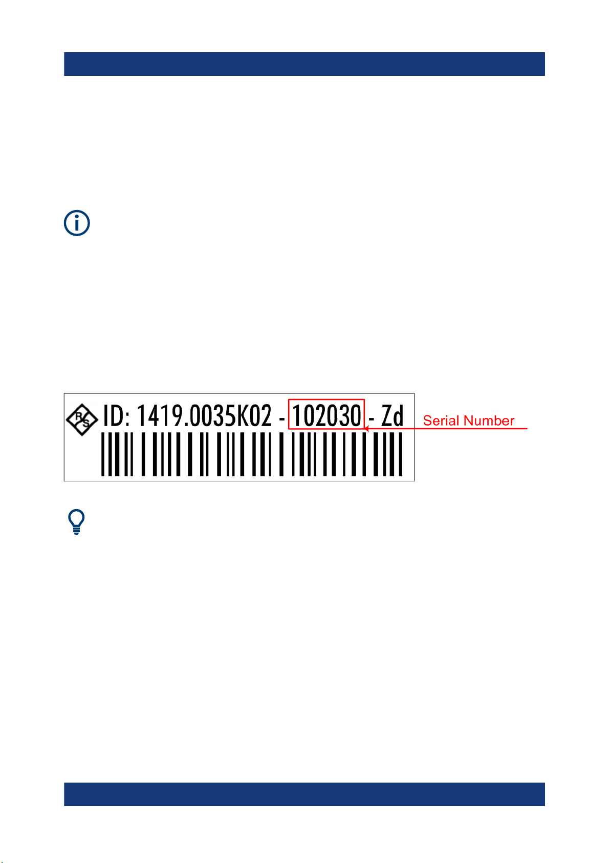
4.2.13 Device ID
The unique device identifier is provided as a barcode sticker on the rear panel of
the R&S ESR.
It consists of the device order number and a serial number.
The serial number is used to define the default instrument name, which is:
<Type><variant>-<serial_number>
For example, ESR3-123456.
The instrument name is required to establish a connection to the instrument
in a LAN.
28Getting Started 1316.3749.02 ─ 09

R&S®ESR
Unpacking and Checking
Preparing For Use
5 Preparing For Use
Here, you can find basic information about setting up the product for the first time.
● Lifting and Carrying......................................................................................... 29
● Unpacking and Checking................................................................................ 29
● Choosing the Operating Site........................................................................... 30
● Setting up the R&S ESR................................................................................. 30
● Placing the R&S ESR on a Bench Top............................................................31
● Mounting the R&S ESR in a Rack...................................................................32
● Connecting the AC Power...............................................................................32
● Connecting to a DC Power Source (Optional)................................................ 33
● Switching the Instrument On and Off.............................................................. 34
● Connecting to LAN.......................................................................................... 35
● Connecting a Keyboard...................................................................................37
● Connecting an External Monitor......................................................................37
● Windows Operating System............................................................................38
● Logging On......................................................................................................40
● Checking the Supplied Options.......................................................................42
● Performing a Self Alignment and a Self Test...................................................42
● Considerations for Test Setup......................................................................... 43
5.1 Lifting and Carrying
The carrying handles are designed to lift or carry the instrument. Do not apply
excessive external force to the handles.
See "Lifting and carrying the product" on page 6.
5.2 Unpacking and Checking
1. Unpack the R&S ESR carefully.
2. Retain the original packing material. Use it when transporting or shipping the
R&S ESR later.
29Getting Started 1316.3749.02 ─ 09

R&S®ESR
3. Using the delivery notes, check the equipment for completeness.
4. Check the equipment for damage.
If the delivery is incomplete or equipment is damaged, contact
Rohde & Schwarz.
Preparing For Use
Setting up the R&S ESR
5.3 Choosing the Operating Site
Specific operating conditions ensure proper operation and avoid damage to the
product and connected devices. For information on environmental conditions
such as ambient temperature and humidity, see the data sheet.
See also "Choosing the operating site" on page 6.
Electromagnetic compatibility classes
The electromagnetic compatibility (EMC) class indicates where you can operate
the product. The EMC class of the product is given in the data sheet under "General data".
●
Class B equipment is suitable for use in:
– Residential environments
– Environments that are directly connected to a low-voltage supply network
that supplies residential buildings
●
Class A equipment is intended for use in industrial environments. It can cause
radio disturbances in residential environments due to possible conducted and
radiated disturbances. It is therefore not suitable for class B environments.
If class A equipment causes radio disturbances, take appropriate measures to
eliminate them.
5.4 Setting up the R&S ESR
See also:
●
"Setting up the product" on page 6
●
"Intended use" on page 5
30Getting Started 1316.3749.02 ─ 09
 Loading...