

Page 1
®
R&S
ESPI
EMI Test Receiver
Quick Start Guide
1164.6613.62 – 02
Quick Start Guide
Test & Measurement
Page 2

The Quick Start Guide describes the following R&S®ESPI models and options:
) R&S ESPI3 (1164.6407K03)
) R&S ESCI7 (1164.6407K07)
The firmware of the instrument makes use of several valuable open source software packages. the most
important of them are listed below, together with their corresponding open source license. The
verbatimlicense texts are provided on the user documentation CD-ROM (included in delivery).
Package Link License
Xitami http://www.xitami.com 2.5b6
PHP http://www.php.net PHP v 3
DOJO-AJAX http://www.dojotoolkit.org BSD License
BOOST Library http://www.boost.org
Boost
Software v.1
ONC/RPC http://www.plt.rwth-aachen.de SUN
TightVnc http://www.tightvnc.com GPL v.3
DemoForgeMirageDriver http://www.demoforge.com/dfmirage.htm GPL v.3
Rohde&Schwarz would like to thank the open source community for their valuable contribution to
embedded computing.
© 2010 Rohde & Schwarz GmbH & Co. KG
81671 Munich, Germany
Printed in Germany – Subject to change – Data without tolerance limits is not binding.
®
is a registered trademark of Rohde & Schwarz GmbH & Co. KG.
R&S
Trade names are trademarks of the owners.
The following abbreviations are used throughout this manual:
®
ESPI is abbreviated as R&S ESPI.
R&S
Page 3

R&S ESPI Contents
Contents
Safety Instructions
Safety Regulations for Batteries
Information on Product Disposal
Certificate of Quality
EC Certificate of Conformity
Support Center Address
List of R&S Representatives
1 Front and Rear Panel . . . . . . . . . . . . . . . . . . . . . . . . . 1.1
1.1 Front View . . . . . . . . . . . . . . . . . . . . . . . . . . . . . . . . . . . . . . . . 1.2
1.2 Function Keys on the Front Panel . . . . . . . . . . . . . . . . . . . . . 1.4
1.3 Front Panel Connections . . . . . . . . . . . . . . . . . . . . . . . . . . . 1.6
1.4 Rear View . . . . . . . . . . . . . . . . . . . . . . . . . . . . . . . . . . . . . . . . . 1.8
1.5 Rear Panel Connections . . . . . . . . . . . . . . . . . . . . . . . . . . . 1.10
2 Preparing for Use . . . . . . . . . . . . . . . . . . . . . . . . . . . . 2.1
2.1 Preparing for Operation . . . . . . . . . . . . . . . . . . . . . . . . . . . . . 2.3
2.1.1 Unpacking the Instrument . . . . . . . . . . . . . . . . . . . . . . . . . 2.3
2.1.2 Setting Up the Instrument . . . . . . . . . . . . . . . . . . . . . . . . . 2.3
2.1.3 Installation in a 19" Rack . . . . . . . . . . . . . . . . . . . . . . . . . . 2.4
2.1.4 Connecting the Instrument to the AC Power Supply . . . . . 2.5
2.1.5 Switching On the R&S ESPI . . . . . . . . . . . . . . . . . . . . . . . 2.5
2.1.6 Functional Test . . . . . . . . . . . . . . . . . . . . . . . . . . . . . . . . . . 2.5
2.1.7 Switching Off the R&S ESPI . . . . . . . . . . . . . . . . . . . . . . . 2.6
2.1.8 Cleaning the Outside . . . . . . . . . . . . . . . . . . . . . . . . . . . . . 2.7
2.2 Instrument Drive Usage . . . . . . . . . . . . . . . . . . . . . . . . . . . . . 2.7
2.3 Connecting External Devices . . . . . . . . . . . . . . . . . . . . . . . . 2.8
2.3.1 Connecting an External Keyboard . . . . . . . . . . . . . . . . . . . 2.8
2.3.2 Connecting a Mouse . . . . . . . . . . . . . . . . . . . . . . . . . . . . 2.10
2.3.3 Connecting an External Monitor . . . . . . . . . . . . . . . . . . . 2.11
2.3.4 Connecting a Printer . . . . . . . . . . . . . . . . . . . . . . . . . . . . 2.12
2.3.5 Connecting USB Devices (e.g. a Power Meter) . . . . . . . . 2.12
Quick Start Guide 1164.6613.62 - 02 1
Page 4

R&S ESPI Contents
2.3.6 Connecting External Generators . . . . . . . . . . . . . . . . . . .2.14
2.3.6.1 Connecting the R&S ESPI to the Generator . . . . . . .2.15
2.3.6.2 Configuring the Generator on the R&S ESPI . . . . . .2.15
2.3.6.3 Activating the Generator Configuration and
Setting the Output Level . . . . . . . . . . . . . . . . . . . . . . . . . . . .2.17
2.3.6.4 Using an External Generator as a Tracking
Generator . . . . . . . . . . . . . . . . . . . . . . . . . . . . . . . . . . . . . . . .2.17
2.4 Setup . . . . . . . . . . . . . . . . . . . . . . . . . . . . . . . . . . . . . . . . . . . .2.18
2.4.1 Selecting the Frequency Reference . . . . . . . . . . . . . . . . .2.18
2.4.2 Setting the Date and Time . . . . . . . . . . . . . . . . . . . . . . . .2.18
2.4.3 Setting the GPIB Interface . . . . . . . . . . . . . . . . . . . . . . . .2.19
2.4.3.1 GPIB Address . . . . . . . . . . . . . . . . . . . . . . . . . . . . . .2.19
2.4.3.2 GPIB Language . . . . . . . . . . . . . . . . . . . . . . . . . . . .2.20
2.4.3.3 ID Response String . . . . . . . . . . . . . . . . . . . . . . . . . .2.21
2.4.4 Setting the Screen Colors . . . . . . . . . . . . . . . . . . . . . . . .2.21
2.4.5 Automatically Switching Off the Internal Screen . . . . . . .2.23
2.4.6 File and Path Selection Using the Front Panel Keys . . . .2.24
2.4.7 Selecting and Configuring Printers . . . . . . . . . . . . . . . . . .2.26
2.4.7.1 Selecting Alternative Printer Configurations . . . . . . .2.27
2.4.7.2 Selecting Printer Colors . . . . . . . . . . . . . . . . . . . . . .2.27
2.4.8 Installing Plug&Play Printers . . . . . . . . . . . . . . . . . . . . . .2.28
2.4.9 Installing Non-Plug&Play Printers . . . . . . . . . . . . . . . . . .2.29
2.5 Configuring the LAN Interface (Option R&S FSP-B16
only) . . . . . . . . . . . . . . . . . . . . . . . . . . . . . . . . . . . . . . . . . . . . . . . .2.29
2.5.1 Connecting the Instrument to the Network . . . . . . . . . . . .2.29
2.5.2 Configuring the Network Card . . . . . . . . . . . . . . . . . . . . .2.29
2.5.2.1 Driver Installation . . . . . . . . . . . . . . . . . . . . . . . . . . .2.29
2.5.2.2 Configuring the Interface . . . . . . . . . . . . . . . . . . . . . .2.30
2.5.2.3 Configuring Existing Network Protocols (TCP/IP
Protocol) . . . . . . . . . . . . . . . . . . . . . . . . . . . . . . . . . . . . . . . . .2.30
2.5.2.4 Installing Additional Network Protocols and
Services . . . . . . . . . . . . . . . . . . . . . . . . . . . . . . . . . . . . . . . . .2.34
2.5.3 Login . . . . . . . . . . . . . . . . . . . . . . . . . . . . . . . . . . . . . . . .2.34
2.6 Operating System Properties . . . . . . . . . . . . . . . . . . . . . . . .2.34
2 Quick Start Guide 1164.6613.62 - 02
Page 5

R&S ESPI Contents
2.6.1 Properties Specific to Windows XP . . . . . . . . . . . . . . . . . 2.34
2.6.1.1 Windows XP Service Packs . . . . . . . . . . . . . . . . . . 2.35
2.6.1.2 Opening the Windows XP Start Menu . . . . . . . . . . . 2.35
2.6.1.3 Windows XP Software Approved for the
Instrument . . . . . . . . . . . . . . . . . . . . . . . . . . . . . . . . . . . . . . . 2.35
3 Firmware Update and Installation of Firmware
Options . . . . . . . . . . . . . . . . . . . . . . . . . . . . . . . . . . . . . . 3.1
3.1 Firmware Update . . . . . . . . . . . . . . . . . . . . . . . . . . . . . . . . . . . 3.2
3.2 Activating Firmware Options . . . . . . . . . . . . . . . . . . . . . . . . . 3.3
4 Basic Operation . . . . . . . . . . . . . . . . . . . . . . . . . . . . . 4.1
4.1 Diagram Layout . . . . . . . . . . . . . . . . . . . . . . . . . . . . . . . . . . . . 4.2
4.1.1 Displays in the Diagram Area . . . . . . . . . . . . . . . . . . . . . . 4.3
4.2 Setting Parameters . . . . . . . . . . . . . . . . . . . . . . . . . . . . . . . . . 4.7
4.2.1 The Keypad . . . . . . . . . . . . . . . . . . . . . . . . . . . . . . . . . . . . 4.7
4.2.2 The Rotary Knob and Arrow Keys . . . . . . . . . . . . . . . . . . . 4.8
4.2.3 Editing Numeric Parameters . . . . . . . . . . . . . . . . . . . . . . . 4.8
4.2.4 Editing Alphanumeric Parameters . . . . . . . . . . . . . . . . . . . 4.9
4.2.4.1 Alphanumeric Editor Type 1: . . . . . . . . . . . . . . . . . . . 4.9
4.2.4.2 Alphanumeric Editor Type 2: . . . . . . . . . . . . . . . . . . 4.10
5 Basic Measurement Examples . . . . . . . . . . . . . . . . . 5.1
5.1 Introduction . . . . . . . . . . . . . . . . . . . . . . . . . . . . . . . . . . . . . . 5.2
5.2 Performing a Level and Frequency Measurement . . . . . . . . 5.3
6 LAN Interface . . . . . . . . . . . . . . . . . . . . . . . . . . . . . . . . 6.1
6.1 Installing Additional Network Protocols & Services . . . . . . 6.3
6.2 Configuration Examples . . . . . . . . . . . . . . . . . . . . . . . . . . . . . 6.6
6.3 Subsequent Changes to the Network Configuration . . . . . . 6.6
6.4 Configuring the Windows XP Firewall . . . . . . . . . . . . . . . . . 6.8
6.5 Operating the Instrument without a Network . . . . . . . . . . . . 6.9
6.6 Operating the Instrument in a Network . . . . . . . . . . . . . . . . . 6.9
6.6.1 Creating Users . . . . . . . . . . . . . . . . . . . . . . . . . . . . . . . . . . 6.9
6.6.2 Changing the User Password . . . . . . . . . . . . . . . . . . . . . 6.11
Quick Start Guide 1164.6613.62 - 02 3
Page 6

R&S ESPI Contents
6.6.3 NOVELL Network only: Configure NOVELL Client . . . . .6.13
6.6.4 Logging On to the Network . . . . . . . . . . . . . . . . . . . . . . . .6.14
6.6.5 Deactivating the Automatic Login Mechanism . . . . . . . . .6.14
6.6.6 Reactivating the Automatic Login Mechanism . . . . . . . . .6.14
6.6.7 Using Network Drives . . . . . . . . . . . . . . . . . . . . . . . . . . . .6.15
6.6.8 Installing a Network Printer . . . . . . . . . . . . . . . . . . . . . . .6.17
6.6.9 Sharing Directories (only with Microsoft Networks) . . . . .6.21
6.7 Manual Operation of the R&S ESPI with XP Remote
Desktop . . . . . . . . . . . . . . . . . . . . . . . . . . . . . . . . . . . . . . . . . . . . .6.24
6.7.1 Introduction . . . . . . . . . . . . . . . . . . . . . . . . . . . . . . . . . . .6.24
6.7.2 Configuring the R&S ESPI for Use of XP Remote
Desktop . . . . . . . . . . . . . . . . . . . . . . . . . . . . . . . . . . . . . . . . . . .6.24
6.7.3 Configuring the Controller . . . . . . . . . . . . . . . . . . . . . . . .6.27
6.7.4 Connection Setup with the R&S ESPI . . . . . . . . . . . . . . .6.30
6.7.5 Interrupting and Restoring the Remote Desktop
Connection with the R&S ESPI . . . . . . . . . . . . . . . . . . . . . . . . .6.33
6.7.6 Deactivating the R&S ESPI from the Controller . . . . . . . .6.34
7 Brief Introduction to Remote Control . . . . . . . . . . . . 7.1
7.1 Basic Steps in Programming using the VISA Interface . . . .7.3
7.1.1 Linking the VISA Library for Visual Basic . . . . . . . . . . . . . .7.3
7.1.1.1 Programming notes: . . . . . . . . . . . . . . . . . . . . . . . . . .7.3
7.1.2 Initialization and Default State . . . . . . . . . . . . . . . . . . . . . .7.4
7.1.2.1 Creating Global Variables . . . . . . . . . . . . . . . . . . . . . .7.4
7.1.2.2 Initializing the Controller . . . . . . . . . . . . . . . . . . . . . . .7.5
7.1.2.3 Initializing the Instrument . . . . . . . . . . . . . . . . . . . . . .7.5
7.1.2.4 Switching the Screen Display On and Off . . . . . . . . . .7.5
7.1.2.5 Configuring the Power Save Function for the
Display . . . . . . . . . . . . . . . . . . . . . . . . . . . . . . . . . . . . . . . . . . .7.6
7.1.3 Sending Simple Instrument Setting Commands . . . . . . . . .7.6
7.1.4 Reading Out Instrument Settings . . . . . . . . . . . . . . . . . . . .7.7
7.1.5 Marker Positioning and Readout . . . . . . . . . . . . . . . . . . . .7.7
7.1.6 Command Synchronization . . . . . . . . . . . . . . . . . . . . . . . .7.8
7.1.6.1 Reading Output Buffers . . . . . . . . . . . . . . . . . . . . . . . .7.9
7.1.6.2 Reading Error Messages . . . . . . . . . . . . . . . . . . . . . .7.9
4 Quick Start Guide 1164.6613.62 - 02
Page 7

R&S ESPI Contents
7.2 Detailed Programming Examples . . . . . . . . . . . . . . . . . . . . . 7.9
7.2.1 Default Settings of the R&S ESPI . . . . . . . . . . . . . . . . . . . 7.9
7.2.1.1 Setting the IEC Bus Status Registers . . . . . . . . . . . . 7.10
7.2.1.2 Default Settings for Measurements . . . . . . . . . . . . . 7.10
7.2.2 Using Markers and Delta Markers . . . . . . . . . . . . . . . . . . 7.12
7.2.2.1 Marker Search Functions, Restricting the Search
Range . . . . . . . . . . . . . . . . . . . . . . . . . . . . . . . . . . . . . . . . . . 7.12
7.2.2.2 Frequency Counting . . . . . . . . . . . . . . . . . . . . . . . . . 7.13
7.2.2.3 Working with a Fixed Reference Point (Reference
Fixed) . . . . . . . . . . . . . . . . . . . . . . . . . . . . . . . . . . . . . . . . . . 7.14
7.2.2.4 Measuring Noise and Phase Noise . . . . . . . . . . . . . 7.15
7.2.3 Reading Out Trace Data . . . . . . . . . . . . . . . . . . . . . . . . . 7.16
7.2.4 Storing and Loading Instrument Settings . . . . . . . . . . . . . 7.19
7.2.4.1 Storing Instrument Settings . . . . . . . . . . . . . . . . . . . 7.19
7.2.4.2 Loading Instrument Settings . . . . . . . . . . . . . . . . . . . 7.19
7.2.4.3 Setting the Data Record for Startup Recall . . . . . . . . 7.20
7.2.5 Configuring and Starting a Printout . . . . . . . . . . . . . . . . . 7.20
Appendix
Appendix A: Printer Interface . . . . . . . . . . . . . . . . . . . . . . . . . . . . . . . . . . . . . . . . . A.1
A.1 Installing USB Printers . . . . . . . . . . . . . . . . . . . . . . . . . . . . . .A.2
A.2 Installing Non-Plug&Play Printers . . . . . . . . . . . . . . . . . . . .A.6
A.2.1 Local Printer . . . . . . . . . . . . . . . . . . . . . . . . . . . . . . . . . . . A.6
A.2.2 Network Printer . . . . . . . . . . . . . . . . . . . . . . . . . . . . . . . .A.12
Appendix B: External Generator Control . . . . . . . . . . . . . . . . . . . . . . . . . . . . . . . . B.1
B.1 List of Generator Types Supported by the R&S ESPI . . . . .B.1
1 Index
Quick Start Guide 1164.6613.62 - 02 5
Page 8

R&S ESPI Contents
6 Quick Start Guide 1164.6613.62 - 02
Page 9

Certificate No.: 2004-39
This is to certify that:
Equipment type Stock No. Designation
ESPI3 1164.6407.03 EMI Test Receiver
ESPI7 1164.6407.07
ESPI-B2 1129.7498.02 Preselector
ESPI-B20 1155.1606.07 Extended Environment Specs
EC Certificate of Conformity
complies with the provisions of the Directive of the Council of the European Union on the
approximation of the laws of the Member States
- relating to electrical equipment for use within defined voltage limits
(2006/95/EC)
- relating to electromagnetic compatibility
(2004/108/EC)
Conformity is proven by compliance with the following standards:
EN61010-1 : 2001-12
EN55011 : 1998 + A1:1999 + A2:2002, Class B
EN61326 : 1997 + A1:1998 + A2:2001 + A3 : 2003
For the assessment of electromagnetic compatibility, instrument class B as well as immunity
to interference for operation in industry have been used as a basis.
Affixing the EC conformity mark as from 2004
ROHDE & SCHWARZ GmbH & Co. KG
Mühldorfstr. 15, D-81671 München
Munich, 2008-04-02 Central Quality Management MF-QZ / Radde
1164.6407.01 CE E-3
Page 10

Page 11

R&S ESPI
Documentation Overview
The documentation of the R&S ESPI consists of base unit manuals and option manuals. All
manuals are provided in PDF format on the CD-ROM delivered with the instrument. Each
software option available for the instrument is described in a separate software manual.
The base unit documentation comprises the following manuals and documents:
• Quick Start Guide
• Operating Manual
• Service Manual
• Internet Site
• Release Notes
Apart from the base unit, these manuals describe the models and options of the R&S ESPI
EMI Test Receiver that are listed in the documentation overview of the Operating Manual. All
other options are described in separate manuals. These manuals are provided on the CDROM. For an overview of all options available for the R&S ESPI visit the R&S ESPI EMI Test
Receiver Internet site.
Quick Start Guide
This manual is delivered with the instrument in printed form and in PDF format on the CDROM. It provides the information needed to set up and start working with the instrument. Basic
operations and basic measurements are described. Also a brief introduction to remote control
is given. More detailed descriptions are provided in the Operating Manual. The Quick Start
Guide includes general information (e.g. Safety Instructions) and the following chapters:
Chapter 1 Front and Rear Panel
Chapter 2 Preparing for Use
Chapter 3 Firmware-Update and Installation of Firmware Options
Chapter 4 Basic Operation
Chapter 5 Basic Measurement Examples
Chapter 6 LAN Interface
Chapter 7 Brief Introduction to Remote Control
Appendix A Printer Interface
Appendix B External Generator Control
Quick Start Guide 1164.6613.62 - 02 0.1
Page 12

R&S ESPI
Operating Manual
This manual is a supplement to the Quick Start Guide and is available in PDF format on the
CD-ROM delivered with the instrument. To retain the familiar structure that applies to all
Operating Manuals of Rohde&Schwarz Test & Measurement instruments, the chapters 1 and
3 exist, but only in form of references to the corresponding Quick Start Guide chapters.
The Operating Manual is subdivided into the following chapters:
Chapter 1 Putting into Operation
see Quick Start Guide chapters 1 and 2.
Chapter 2 Getting Started
see Quick Start Guide chapter 5.
Chapter 3 Manual Operation
see Quick Start Guide chapter 4
Chapter 4 Instrument Functions
forms a reference for manual operation of the R&S ESPI and contains a
detailed description of all instrument functions and their application.
Chapter 5 Remote Control - Basics
describes the basics for programming the R&S ESPI, command processing
and the status reporting system.
Chapter 6 Remote Control - Description of Commands
lists all the remote-control commands defined for the instrument.
Chapter 7 Remote Control - Programming Examples
contains program examples for a number of typical applications of the R&S
ESPI.
Chapter 8 Maintenance and Instrument Interfaces
describes preventive maintenance and the characteristics of the instrument’s
interfaces.
Chapter 9 Error Messages
gives a list of error messages that the R&S ESPI may generate.
Index contains an index for the chapters 1 to 9 of the Operating Manual.
Service Manual
This manual is available in PDF format on the CD-ROM delivered with the instrument. It
informs on how to check compliance with rated specifications, on instrument function, repair,
troubleshooting and fault elimination. It contains all information required for repairing the R&S
ESPI by the replacement of modules. The manual includes the following chapters:
Chapter 1 Performance Test
Chapter 2 Adjustment
Chapter 3 Repair
Chapter 4 Software Update / Installing Options
Chapter 5 Documents
0.2 Quick Start Guide 1164.6613.62 - 02
Page 13

R&S ESPI
Internet Site
The Internet site at: R&S ESPI EMI Test Receiver provides the most up to date information on
the R&S ESPI. The current operating manual at a time is available as printable PDF file in the
download area. Also provided for download are firmware updates including the associated
release notes, instrument drivers, current data sheets and application notes.
Release Notes
The release notes describe the installation of the firmware, new and modified functions,
eliminated problems, and last minute changes to the documentation. The corresponding
firmware version is indicated on the title page of the release notes. The current release notes
are provided in the Internet.
Quick Start Guide 1164.6613.62 - 02 0.3
Page 14

R&S ESPI
0.4 Quick Start Guide 1164.6613.62 - 02
Page 15

R&S ESPI Front and Rear Panel
1 Front and Rear Panel
1.1 Front View . . . . . . . . . . . . . . . . . . . . . . . . . . . . . . . . . . . . . . . . . . . . . . . . . . . 1.2
1.2 Function Keys on the Front Panel . . . . . . . . . . . . . . . . . . . . . . . . . . . . . . . 1.4
1.3 Front Panel Connections . . . . . . . . . . . . . . . . . . . . . . . . . . . . . . . . . . . . . . . 1.6
1.4 Rear View . . . . . . . . . . . . . . . . . . . . . . . . . . . . . . . . . . . . . . . . . . . . . . . . . . . 1.8
1.5 Rear Panel Connections . . . . . . . . . . . . . . . . . . . . . . . . . . . . . . . . . . . . . . 1.10
Quick Start Guide 1164.6613.62 - 02 1.1
Page 16
R&S ESPI Front and Rear Panel
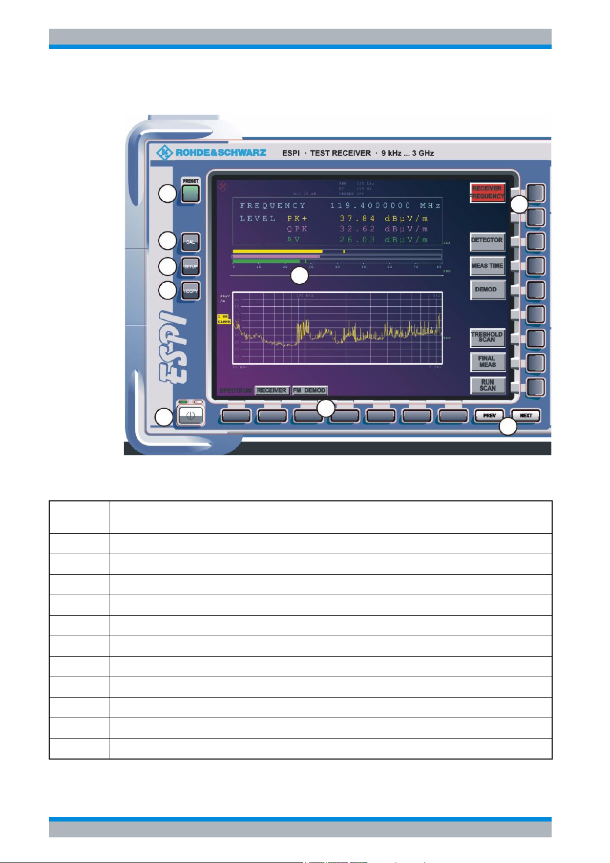
Front View
1.1 Front View
1
8
2
3
5
4
7
6
Fig. 1-1
Number
in Fig. 1-1
1 PRESET key (see “ Function Keys on the Front Panel”)
2 Calibration key (see “ Function Keys on the Front Panel”)
Front view
Description
9
3 SETUP key (see “ Function Keys on the Front Panel”)
4 HCOPY key (see “ Function Keys on the Front Panel”)
5 screen
6 ON/standby switch (see “ Function Keys on the Front Panel”)
7 hotkeys
8 softkeys
9 PREVIOUS key, NEXT key (softkey side menus)
10 function keys for frequency, level, and markers (see “ Function Keys on the Front Panel”)
11 numeric keypad, units and entry keys
1.2 Quick Start Guide 1164.6613.62 - 02
Page 17
R&S ESPI Front and Rear Panel
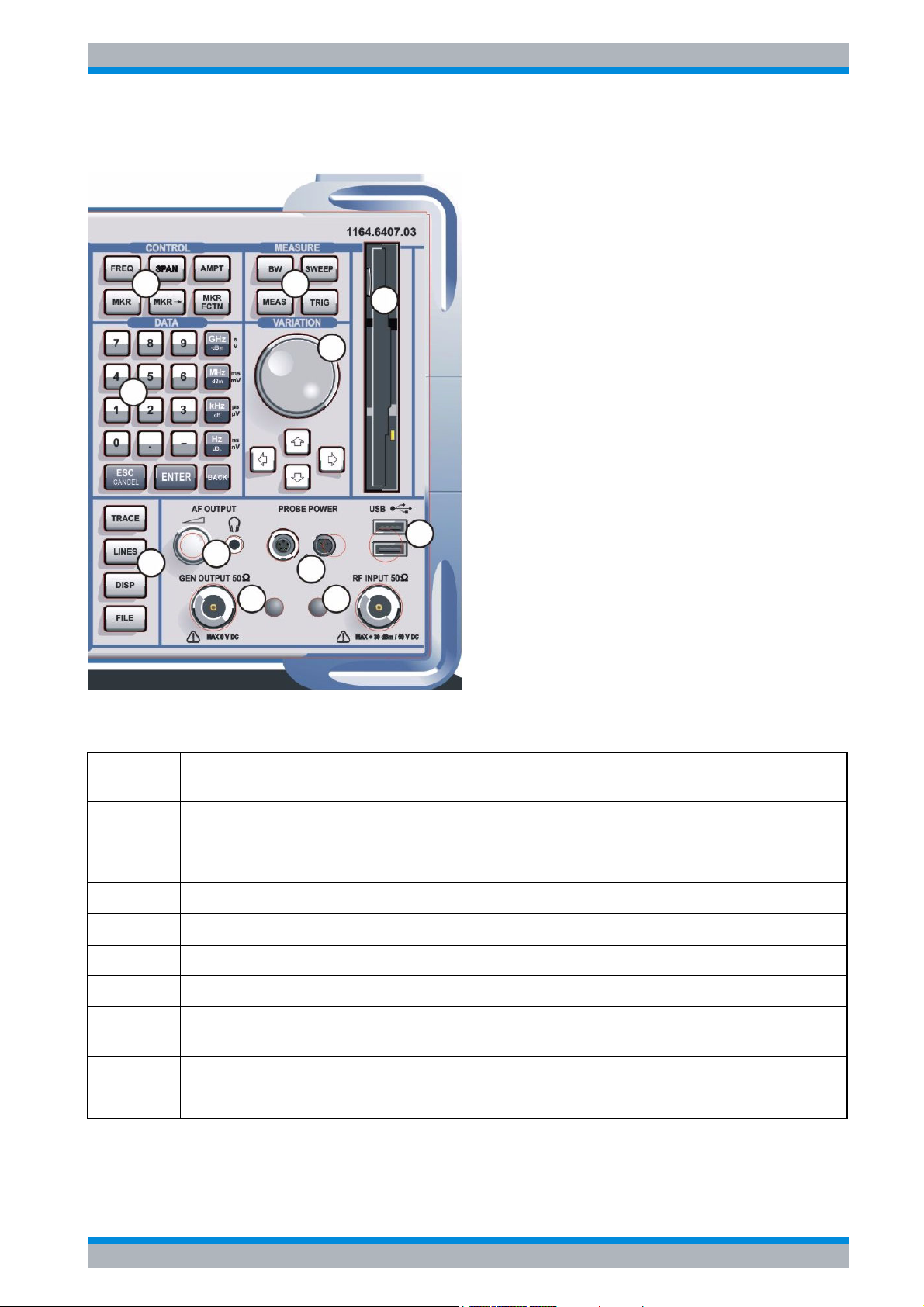
Front View
11
10
12
13
14
18
20
19
17
15
16
Number
in Fig. 1-1
12 TRACE key, LINES key, DISP key, FILE key
13 AF output with volume control (see page 6)
14 generator output, option R&S FSP-B9 (see page 22)
15 probe power connector - supply voltage for measurement accessories (see page 7)
16 RF input (see page 6)
17 USB interface
18 function keys for bandwidth, sweep, trigger and measurement functions
19 rotary knob with enter function and arrow keys
20 3 1/2" diskette drive; 1.44 MByte
Description
(see “ Function Keys on the Front Panel”)
(see “ Function Keys on the Front Panel”)
Quick Start Guide 1164.6613.62 - 02 1.3
Page 18
R&S ESPI Front and Rear Panel
Function Keys on the Front Panel
1.2 Function Keys on the Front Panel
A detailed description of the corresponding menus and the other function keys is provided in
the Operating Manual on CD-ROM.
Function key Assigned functions
ON/STANDBY Switches the instrument on and off.
PRESET Resets the instrument to the default state.
FREQ Sets the center frequency as well as the start and stop frequencies for the
frequency band under consideration. This key is also used to set the frequency
offset and the signal track function.
SPAN Sets the frequency span to be analyzed.
AMPT Sets the reference level, the displayed dynamic range, the RF attenuation and
the unit for the level display. This key is also used to set the level offset and the
input impedance.
MKR Sets and positions the absolute and relative measurement markers (markers
and delta markers). In addition, the following measurement functions are
assigned under this key:
• Frequency counter (SIGNAL COUNT)
• Fixed reference point for relative measurement markers (REFERENCE
FIXED)
• Enlargement of the measurement area (MARKER ZOOM)
MKR-> Used for search functions of the measurement markers (maximum/minimum of
the trace).
Assigns the marker frequency to the center frequency, and the marker level to
the reference level.
Restricts the search area (SEARCH LIMITS) and characterizes the maximum
points and minimum points (PEAK EXCURSION).
MKR FCTN Provides additional analysis functions of the measurement markers:
• Noise marker (NOISE MEAS)
• Phase noise (PHASE NOISE)
• n dB down function
• AM/FM audio demodulation (analyzer)
• Peak list
BW Sets resolution bandwidth, video bandwidth and the two ratios "resolution
bandwidth/video bandwidth" and "span/resolution bandwidth" in the case of
automatic coupling.
SWEEP Sets the scan parameters.
Sets the sweep time and the number of measurement points.
Selects continuous measurement or single measurement.
1.4 Quick Start Guide 1164.6613.62 - 02
Page 19
R&S ESPI Front and Rear Panel
Function Keys on the Front Panel
Function key Assigned functions
MEAS Selects the measurement function (receiver mode):
• Detector and the measurement time selection
• AF demodulator (receiver mode)
• Data reduction and peak list
• Threshold scan
• Final measurement functions
Used to perform complex measurement functions (analyzer mode):
• Measurement of time domain power (TIME DOM POWER)
• Measurement of channel and adjacent channel power (CHAN PWR ACP)
• Measurement of multicarrier adjacent channel power (MULT CARR ACP)
• Occupied bandwidth (OCCUPIED BANDWIDTH)
• Signal statistics (SIGNAL STATISTIC): amplitude probability distribution
(APD) and cumulative complementary distribution function (CCDF)
• Carrier to noise spacing (C/N C/No)
• AM modulation depth (MODULATION DEPTH)
• Spurious emissions (SPURIOUS EMISSIONS)
• Third-order intercept point (TOI)
TRIG Sets trigger source, trigger threshold, trigger delay, and gate configuration in the
case of gated sweep.
TRACE Configures measured data acquisition (CLR/WRITE; AVERAGE, MAXHOLD;
MINHOLD, VIEW). Configures the analysis of the measurement data
(DETECTOR) and the mathematical linking of traces (TRACE MATH).
LINES Configures display lines and limit lines.
DISP Configures the screen layout (one/two diagrams) and the diagram contents. This
key can also be used to configure the screen colors.
FILE Provides the functions for storing/loading instrument settings and for managing
stored files.
CAL Used to perform instrument self-calibration.
SETUP Used to set or display the following the default settings of the instrument:
• Reference frequency, noise source, preamplifier, preselector, level correction
values (TRANSDUCER), date, time, GPIB, RS-232-C interface, LAN interface
• Firmware update and enabling of options
• Information about instrument configuration (SYSTEM INFO) incl. firmware
version, module data and system error messages
• Service support functions
HCOPY Configures the screen printout, and selects and configures the printer.
Quick Start Guide 1164.6613.62 - 02 1.5
Page 20
R&S ESPI Front and Rear Panel
Front Panel Connections
1.3 Front Panel Connections
This section describes the front connectors and interfaces of the R&S ESPI. Optional
connectors and interfaces are indicated by the option name in brackets.
RF INPUT 50
The RF input (20 Hz ... f
appropriate connector. Be sure not to overload the input. The maximum continuous power at
the RF input is +30 dBm (1 W).
The maximum DC voltage is 50 V, the maximum power is 1 W (≥ 30 dBm) at ≥ 10 dB
attenuation.
Ω
) is to be connected to the DUT via a cable equipped with an
max
Tracking Generator Output (GEN OUTPUT 50Ω, Option R&S FSP-B9)
The output of the tracking generator is to be connected to the DUT via a cable equipped with
a male N connector.
The female connector is available only with the tracking generator option (R&S FSP-B9).
In the case of DUTs with sensitive HF characteristics with regard to
matching (VSWR) at the input, insert a 20 dB attenuator between the
DUT and the tracking generator.
AF OUTPUT
A miniature headphone jack can be used at the AF OUTPUT connector to connect an external
loudspeaker, a headphone set or, e.g., a LF voltmeter.
The internal impedance is 10 Ω. The output voltage can be set by using the volume control to
the left of the connector. If a jack is plugged in, the internal loudspeaker will automatically be
switched off.
Check the volume setting carefully before putting on the headphones in order to protect
your hearing.
1.6 Quick Start Guide 1164.6613.62 - 02
Page 21
R&S ESPI Front and Rear Panel
Front Panel Connections
PROBE POWER
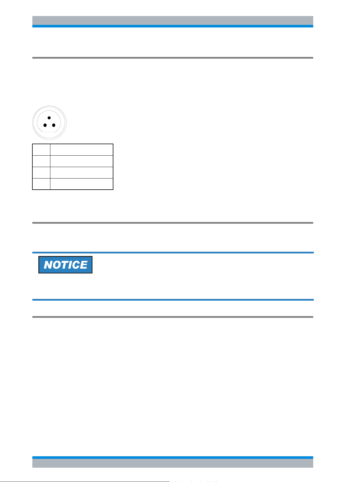
To allow the connection of probes, the R&S ESPI provides the PROBE POWER power
connectors. The 3-pole connector delivers the power supply voltages +15 V and -12,6 V and
ground.
The connector is also suited for powering the high-impedance probes from Hewlett Packard.
1
23
Pin Signal
1GND
2 -12.6 V; max. 150 mA
3 +15 V; max. 150 mA
Fig. 1-2 Pin assignments of PROBE POWER connector
USB Interfaces
The R&S ESPI provides a USB female connector at the front panel for connecting two USB
devices (USB 2.0). For pin assignment see page 12.
Use suitable double shielded cables.
Use only USB devices that keep the permissible EMI limits.
Disk Drive
The front panel provides a 3.5” disk drive for 1.44 MByte floppy disks.
Quick Start Guide 1164.6613.62 - 02 1.7
Page 22
R&S ESPI Front and Rear Panel
Rear View
1.4 Rear View
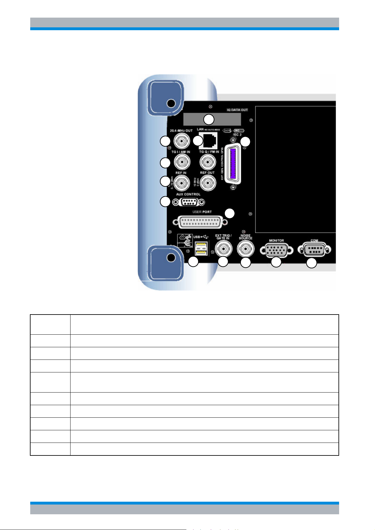
2
Fig. 1-3 Rear view
Number in
Fig. 1-3
Description
34
5
6
7
9
10
1
8
11
12
13
1 second GPIB interface for external generator control, option R&S FSP-B10 (see page 14)
2 reserved for options
3 LAN interface, option R&S FSP-B16 (see page 58)
4 IF output 20.4 MHz (see page 13); with option R&S FSP-B6, this output is replaced by the
switchable CCVS input/output (see page 14)
5 I/Q input for tracking generator, option R&S FSP-B9 (see page 14)
6 input/output for external/internal reference (see page 13)
7 external generator control, option R&S FSP-B10 (see page 15)
8 user port (see page 12)
9 double USB interface (see page 12)
1.8 Quick Start Guide 1164.6613.62 - 02
Page 23
R&S ESPI Front and Rear Panel
Rear View
16
14
Number in
Fig. 1-3
10 trigger/gate interface (see page 11)
11 noise source supply voltage (see page 11)
12 VGA interface for external monitor (see page 11)
13 RS232-C interface (see page 10)
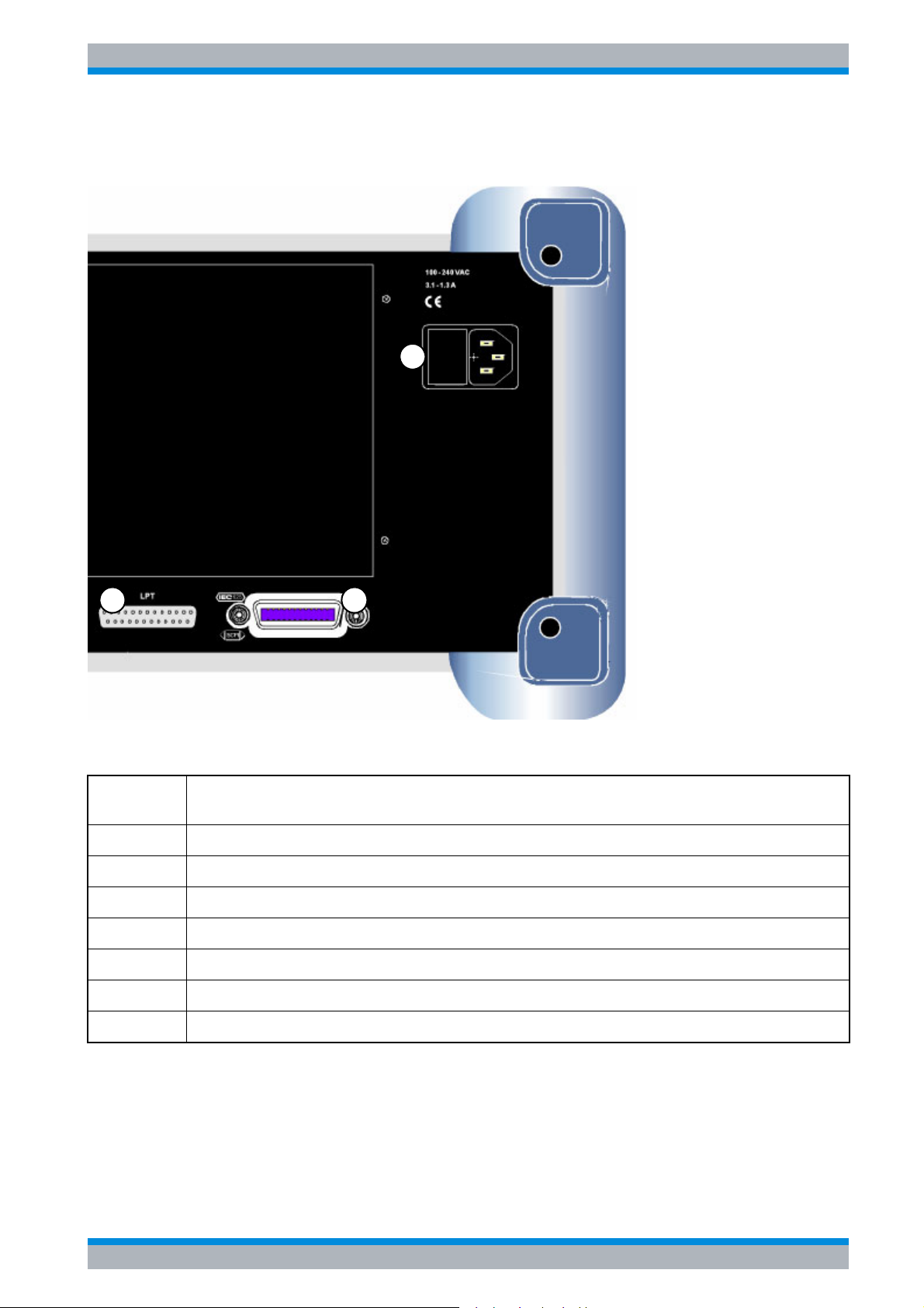
14 LPT printer interface (see page 10)
15 GPIB interface for remote control (see page 10)
16 AC power supply connector with on/off switch (see page 10)
Description
15
Quick Start Guide 1164.6613.62 - 02 1.9
Page 24

R&S ESPI Front and Rear Panel
Rear Panel Connections
1.5 Rear Panel Connections
This section describes the rear connectors and interfaces of the R&S ESPI. Optional
connectors and interfaces are indicated by the option name in brackets.
AC Power Supply Connection and Main Power Switch
An AC power supply connector and main power switch are located in a unit on the rear panel
of the instrument.
Main power switch function:
Position I After being switched on, the instrument will be either in standby mode or in
operation depending on the setting of the ON/STANDBY switch on the front
panel of the instrument.
Position O Switching the instrument off disconnects the entire instrument from the AC
power supply.
The main power switch also interrupts the power supply of the OCXO
located in the instrument. When you switch the instrument back on, be
sure to comply with the extended warm-up phase specified in the data
sheet.
GPIB Interface
The instrument comes with a GPIB interface in compliance with IEEE488. A controller for
remote control can be connected via this interface. Use a shielded cable to set up the
connection. For further information refer to the Operating Manual, chapter 8.
Printer Interface (LPT)
The 25-pin female LPT connector on the rear panel of the R&S ESPI is provided for
connecting a printer. The interface is compatible with the CENTRONICS interface. For further
information refer to the Operating Manual, chapter 8.
RS-232-C Interface (COM)
The instrument comes with an RS-232-C interface. The interface can be manually activated
and configured for remote control by defining the parameters in the COM INTERFAC table,
which is accessed from the SETUP - GENERAL SETUP menu. For further information refer
to the Operating Manual, chapter 8.
1.10 Quick Start Guide 1164.6613.62 - 02
Page 25
R&S ESPI Front and Rear Panel
Rear Panel Connections
R&S Monitor Connection (MONITOR)
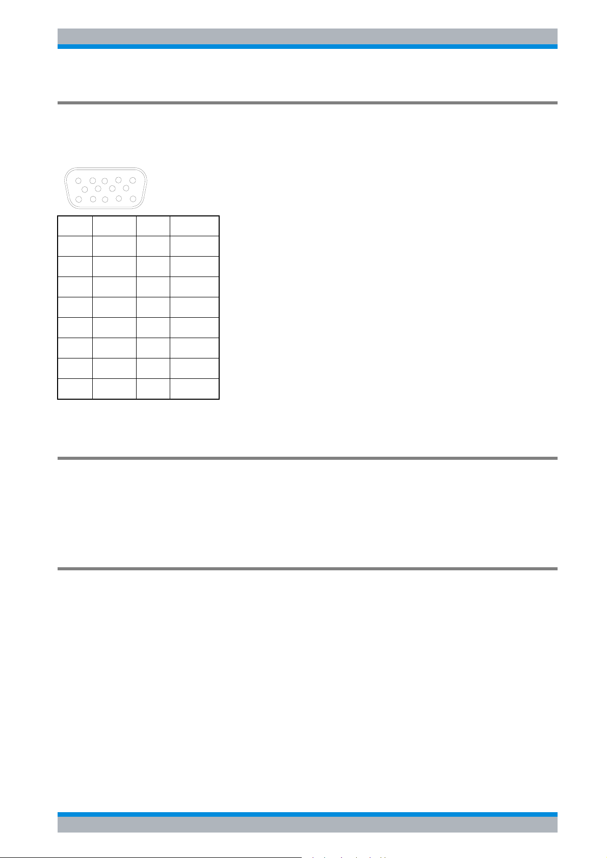
The 15-pin VGA monitor connection is used to display the screen contents on an external
screen. The procedure for putting the external monitor into operation is described in the
section “ Connecting an External Monitor” on page 2.11.
5
10
15
Pin Signal Pin Signal
1R 9GND
2G 10GND
3 B 11 (NC)
4 (NC) 12 (NC)
5 GND 13 HSYNC
6 GND 14 VSYNC
7 GND 15 (NC)
8GND
1
6
11
Fig. 1-4 Pin assignments of the MONITOR connection
Noise Source Control (NOISE SOURCE)
Using the NOISE SOURCE connector, an external noise source can be switched on/off, in
order, e.g., to measure the noise figure of (DUTs).
Usual noise sources require a +28 V signal to be turned on. At 0 V, they are turned off. These
supply voltages are delivered by the connector. Maximum current is 100 mA.
Input for External Trigger (EXT TRIG/GATE IN)
The EXT TRIG/GATE IN female connector is used to control the measurement by means of
an external signal.
The voltage levels are adjustable (0.5 V to 3.5 V). The typical input impedance is 10 kΩ.
Quick Start Guide 1164.6613.62 - 02 1.11
Page 26
R&S ESPI Front and Rear Panel
Rear Panel Connections
USB Interface
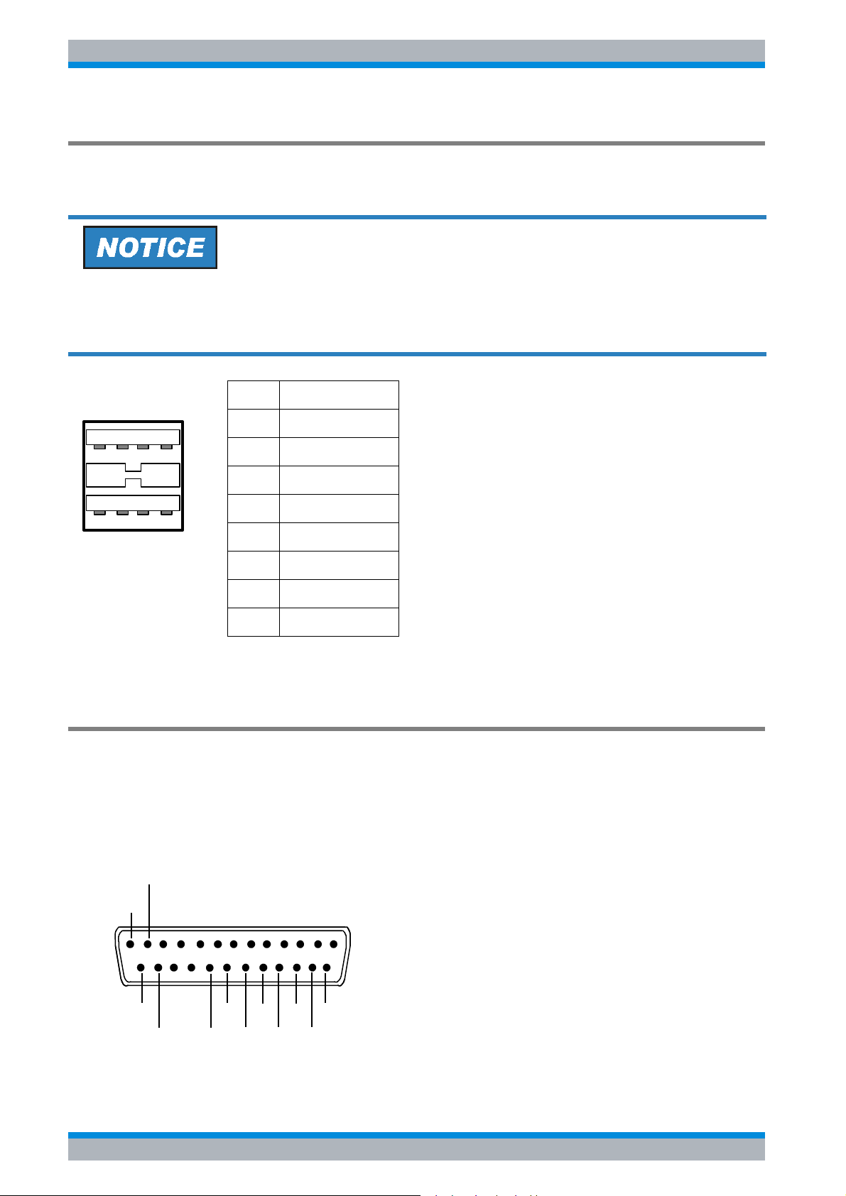
The R&S ESPI provides a USB female connector at the rear panel for connecting two USB
devices (upper connector USB 1.1, lower connector USB 2.0).
Use suitable double shielded cables. Passive USB connecting cables must not exceed 1 m
in length.
Use only USB devices that keep the permissible EMI limits.
Pin Signal
1 + 5 V USB0
1 2 3 4
5 6 7 8
2 USBDATA0 -
3 USBDATA0 +
4GND
5 + 5 V USB1
6 USBDATA1 -
7 USBDATA1 +
8GND
Fig. 1-5 USB connector assignment
USER PORT
The user interface is a 25 pin Cannon connector which provides access to the user port. The
port is 8 bits wide (A0 - A7) and can be configured either as output or as input. The voltage
levels are TTL levels (Low < 0,4 V, High > 2 V).
In addition, the internal +5 V and +12 V power supply voltages are provided. The maximum
load current is 100 mA.
GND
+5 V
13
25
+12 V
GND
A7
A6
A5
A4
A3
A2
A1
1
14
A0
1.12 Quick Start Guide 1164.6613.62 - 02
Page 27
R&S ESPI Front and Rear Panel
Rear Panel Connections
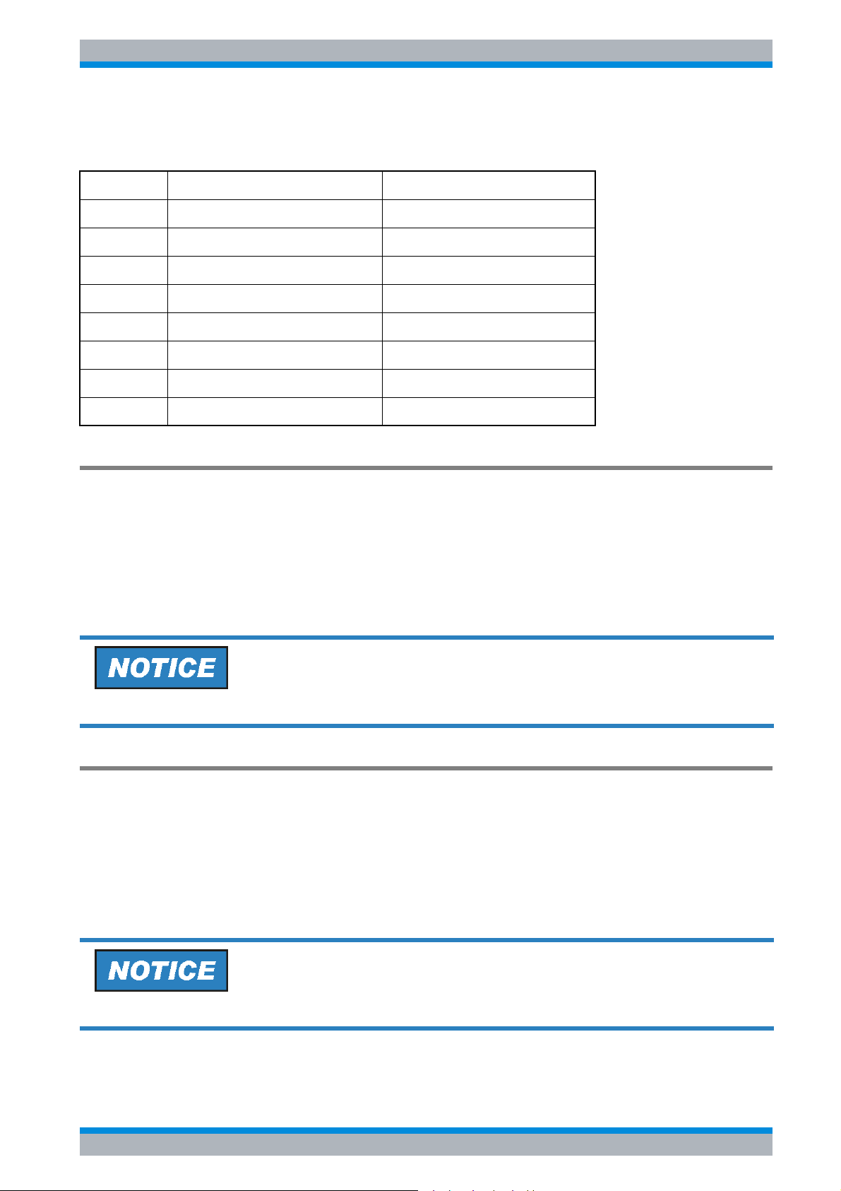
The user ports are configured in the SETUP menu (SETUP key), GENERAL SETUP /
USER PORT sub-menu.
Pin Signal Range of values
1 to 11 not used
12 ground
13 +5 V supply voltage 5.2 V ± 0.5 V, max. 30 mA
14 to 20 reserved
21 ready-for-trigger output signal HIGH: ≥ 1.4 V, LOW: ≤ 0.7 V
22 to 23 not used
24 ground
25 +12 V supply voltage +12 V ± 0.5 V, max. 10 mA
Reference Input and Output (REF IN and REF OUT)
The REF IN female connector is used as an input for a 10 MHz reference signal. The required
input level is 0 to 10 dBm. The REF OUT female connector provides the internal 10 MHz
reference signal with a 0 dBm output level for other devices.
The SETUP menu is used to select between the internal and external references.
If an external reference is used for operation, the external reference signal from REF IN is
looped through to REF OUT.
Use suitable double shielded cables.
20.4 MHz IF Output (IF OUT 20.4 MHz)
The 20.4 MHz IF signal of the R&S ESPI is provided at the 20.4 MHz OUT female BNC
connector. For resolution bandwidths between 100 kHz and 10 MHz, the bandwidth
corresponds to the selected bandwidth. For bandwidths ≤100 kHz, the bandwidth of the output
is equal to 2.6 * resolution bandwidth, where the minimum value is 2.6 kHz (non-FFT). In the
analyzer mode, the level at the IF output in the case of a signal at the reference level is 0 dBm
if the resolution bandwidth is ≥100 kHz; if the resolution bandwidth is <100 kHz, the level is
-10 dBm (for mixer levels ≥ -60 dBm).
Use suitable double shielded cables.
Quick Start Guide 1164.6613.62 - 02 1.13
Page 28
R&S ESPI Front and Rear Panel
Rear Panel Connections
With option R&S FSP-B6, this output is replaced by the CCVS IN/ OUT
connector.
CCVS Output and Input (CCVS IN/OUT, Option R&S FSP-B6)
The CCVS IN/OUT female BNC connector is a switchable CCVS input/output. If TV triggering
is activated and triggering occurs in response to the internal demodulator signal (CCVS INT),
the demodulated TV signal is provided for operating an CCVS monitors. If triggering occurs in
response to an externally supplied CCVS signal (CCVS EXT), the female connector serves as
an input.
TG I / AM IN; TG Q / FM IN (Option R&S FSU-B9)
The two female connectors TG I /AM IN and TG Q /FM IN are used to modulate the tracking
generator (option R&S FSU-B9) by means of an external signal.
The input voltage range is ±0.5 V; the input impedance is 50 Ω.
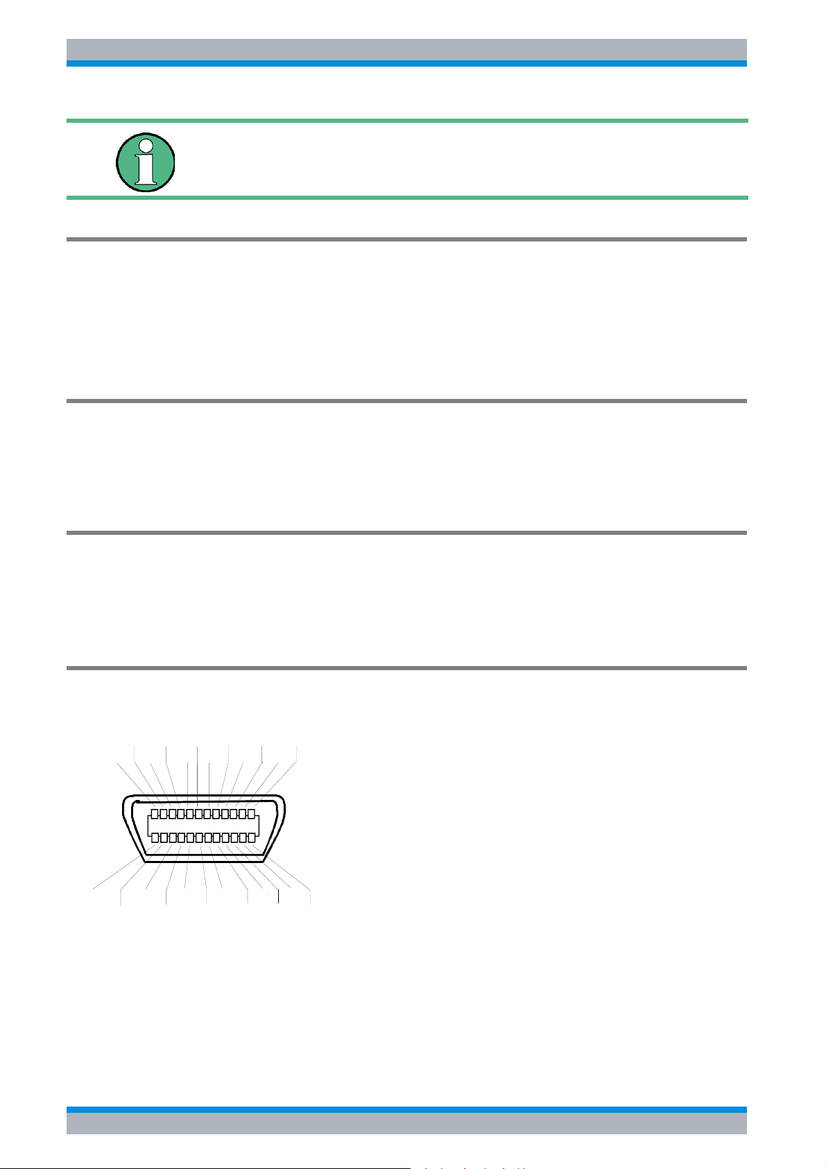
LAN Interface (Option R&S FSP-B16)
The LAN interface can be used to connect to a local network. The assignment of the RJ-45
connector supports twisted-pair category 5 UTP/STP cables in a star configuration (UTP
stands for “unshielded twisted pair”, and STP for “shielded twisted pair”).
Second GPIB Interface IEC2 (Option R&S FSP-B10)
When equipped with option R&S FSP-B10 (external generator control), the instrument
provides a second GPIB interface for using external generators.
ATN IFC NRFD EOI DIO3 DIO1
SHIELD SRQ NDAC DAV DIO4 DIO2
12
24
1
13
LOGIC GND GND(10) GND(8) G ND(6) DIO8 DIO6
GND(11) GND(9) GND(7) REN DIO7 DIO5
Fig. 1-6 Pin assignment of the second IEC interface
1.14 Quick Start Guide 1164.6613.62 - 02
Page 29
R&S ESPI Front and Rear Panel
Rear Panel Connections
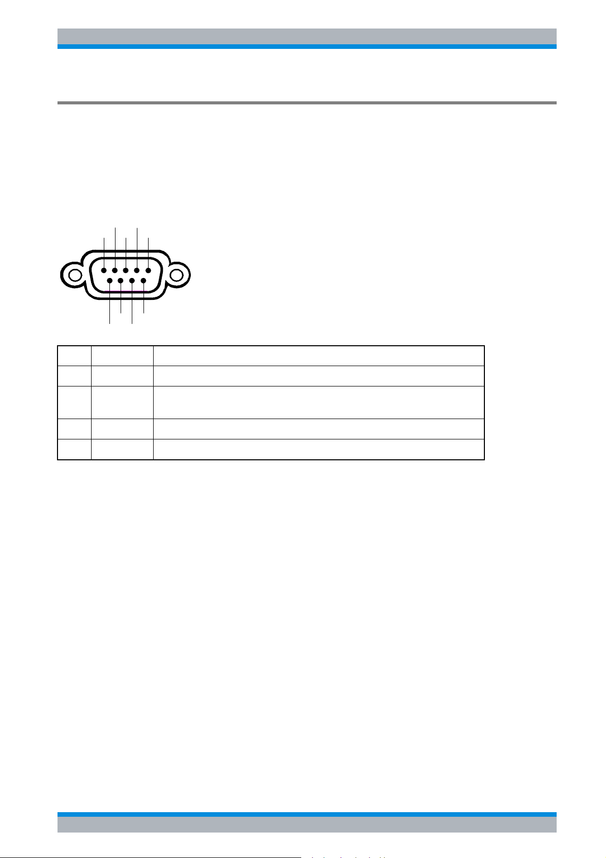
AUX CONTROL (Option R&S FSP-B10)
The optional AUX CONTROL interface is associated with the option FSP-B10 (External
Generator Control). It allows fast frequency switching with the external generator control
option when a Rohde & Schwarz signal generator is used.
The cable supplied is used to connect the interface to the corresponding interface of the signal
generator (see also section " External Generator Control Option - FSP-B10). The voltage
levels are of the TTL type (low < 0.4 V, high > 2 V).
Blank
n.c.
n.c.
Trigger
n.c.
GND
34
GND
5
GND
1
2
6789
GND
Pin Signal Description
1 n.c. not connected
2 BLANK Return signalling from the signal generator indicating that frequency
setting is completed
3 TRIGGER Trigger signal for switching to the next frequency
6...9 GND Ground
Fig. 1-7 Pin assignment of the AUX CONTROL connector
Quick Start Guide 1164.6613.62 - 02 1.15
Page 30

R&S ESPI Front and Rear Panel
Rear Panel Connections
1.16 Quick Start Guide 1164.6613.62 - 02
Page 31

R&S ESPI Preparing for Use
2 Preparing for Use
2.1 Preparing for Operation . . . . . . . . . . . . . . . . . . . . . . . . . . . . 2.3
2.1.1 Unpacking the Instrument . . . . . . . . . . . . . . . . . . . . . . . . 2.3
2.1.2 Setting Up the Instrument . . . . . . . . . . . . . . . . . . . . . . . . 2.3
2.1.3 Installation in a 19" Rack . . . . . . . . . . . . . . . . . . . . . . . . . 2.4
2.1.4 Connecting the Instrument to the AC Power Supply . . . . 2.5
2.1.5 Switching On the R&S ESPI . . . . . . . . . . . . . . . . . . . . . . 2.5
2.1.6 Functional Test . . . . . . . . . . . . . . . . . . . . . . . . . . . . . . . . . 2.5
2.1.7 Switching Off the R&S ESPI . . . . . . . . . . . . . . . . . . . . . . 2.6
2.1.8 Cleaning the Outside . . . . . . . . . . . . . . . . . . . . . . . . . . . . 2.7
2.2 Instrument Drive Usage . . . . . . . . . . . . . . . . . . . . . . . . . . . . 2.7
2.3 Connecting External Devices . . . . . . . . . . . . . . . . . . . . . . . 2.8
2.3.1 Connecting an External Keyboard . . . . . . . . . . . . . . . . . . 2.8
2.3.2 Connecting a Mouse . . . . . . . . . . . . . . . . . . . . . . . . . . . 2.10
2.3.3 Connecting an External Monitor . . . . . . . . . . . . . . . . . . 2.11
2.3.4 Connecting a Printer . . . . . . . . . . . . . . . . . . . . . . . . . . . 2.12
2.3.5 Connecting USB Devices (e.g. a Power Meter) . . . . . . . 2.12
2.3.6 Connecting External Generators . . . . . . . . . . . . . . . . . . 2.14
2.3.6.1 Connecting the R&S ESPI to the Generator . . . . . . 2.15
2.3.6.2 Configuring the Generator on the R&S ESPI . . . . . 2.15
2.3.6.3 Activating the Generator Configuration and Setting
the Output Level . . . . . . . . . . . . . . . . . . . . . . . . . . . . . . . . . 2.17
Quick Start Guide 1164.6613.62 - 02 2.1
Page 32

R&S ESPI Preparing for Use
2.3.6.4 Using an External Generator as a Tracking
Generator . . . . . . . . . . . . . . . . . . . . . . . . . . . . . . . . . . . . . . . 2.17
2.4 Setup . . . . . . . . . . . . . . . . . . . . . . . . . . . . . . . . . . . . . . . . . . . 2.18
2.4.1 Selecting the Frequency Reference . . . . . . . . . . . . . . . . 2.18
2.4.2 Setting the Date and Time . . . . . . . . . . . . . . . . . . . . . . . 2.18
2.4.3 Setting the GPIB Interface . . . . . . . . . . . . . . . . . . . . . . . 2.19
2.4.3.1 GPIB Address . . . . . . . . . . . . . . . . . . . . . . . . . . . . . 2.19
2.4.3.2 GPIB Language . . . . . . . . . . . . . . . . . . . . . . . . . . . . 2.20
2.4.3.3 ID Response String . . . . . . . . . . . . . . . . . . . . . . . . . 2.21
2.4.4 Setting the Screen Colors . . . . . . . . . . . . . . . . . . . . . . . 2.21
2.4.5 Automatically Switching Off the Internal Screen . . . . . . 2.23
2.4.6 File and Path Selection Using the Front Panel Keys . . . 2.24
2.4.7 Selecting and Configuring Printers . . . . . . . . . . . . . . . . . 2.26
2.4.7.1 Selecting Alternative Printer Configurations . . . . . . 2.27
2.4.7.2 Selecting Printer Colors . . . . . . . . . . . . . . . . . . . . . . 2.27
2.4.8 Installing Plug&Play Printers . . . . . . . . . . . . . . . . . . . . . 2.28
2.4.9 Installing Non-Plug&Play Printers . . . . . . . . . . . . . . . . . 2.29
2.5 Configuring the LAN Interface (Option R&S FSP-B16
only) . . . . . . . . . . . . . . . . . . . . . . . . . . . . . . . . . . . . . . . . . . . . . . . 2.29
2.5.1 Connecting the Instrument to the Network . . . . . . . . . . . 2.29
2.5.2 Configuring the Network Card . . . . . . . . . . . . . . . . . . . . 2.29
2.5.2.1 Driver Installation . . . . . . . . . . . . . . . . . . . . . . . . . . . 2.29
2.5.2.2 Configuring the Interface . . . . . . . . . . . . . . . . . . . . . 2.30
2.5.2.3 Configuring Existing Network Protocols (TCP/IP
Protocol) . . . . . . . . . . . . . . . . . . . . . . . . . . . . . . . . . . . . . . . . 2.30
2.5.2.4 Installing Additional Network Protocols and
Services . . . . . . . . . . . . . . . . . . . . . . . . . . . . . . . . . . . . . . . . 2.34
2.5.3 Login . . . . . . . . . . . . . . . . . . . . . . . . . . . . . . . . . . . . . . . 2.34
2.6 Operating System Properties . . . . . . . . . . . . . . . . . . . . . . . 2.34
2.6.1 Properties Specific to Windows XP . . . . . . . . . . . . . . . . 2.34
2.6.1.1 Windows XP Service Packs . . . . . . . . . . . . . . . . . . . 2.35
2.6.1.2 Opening the Windows XP Start Menu . . . . . . . . . . . 2.35
2.6.1.3 Windows XP Software Approved for the
Instrument . . . . . . . . . . . . . . . . . . . . . . . . . . . . . . . . . . . . . . 2.35
2.2 Quick Start Guide 1164.6613.62 - 02
Page 33

R&S ESPI Preparing for Use
Preparing for Operation
2.1 Preparing for Operation
This section describes how to put the instrument into operation.
Before putting the instrument into operation, make sure that the following requirements
have been met:
• The air vents are not blocked.
• No signal voltage levels exceeding the permitted limits are present at the inputs.
• The instrument's outputs are neither overloaded nor incorrectly connected.
Not complying with these requirements can result in damage to the instrument.
2.1.1 Unpacking the Instrument
➢ Remove the instrument from its packaging and check the equipment for completeness
using the delivery note and the accessory lists for the various items.
➢ First, pull off the polyethylene protection pads from the instrument's rear feet and then
carefully remove the pads from the instrument handles at the front.
➢ Pull off the corrugated cardboard cover that protects the rear of the instrument.
➢ Carefully unthread the corrugated cardboard cover at the front that protects the instrument
handles and remove it.
➢ Check the instrument for any damage. If there is damage, immediately contact the carrier
who delivered the instrument. In this case, make sure not to discard the box and packing
material.
It is advisable to keep the original packing material in order to prevent control elements and
connectors from being damaged in case the instrument is to be transported or shipped at a
later date.
Protective plastic caps for the front panel and the rear panel can be ordered addditionally
(order number 1096.7095.00). Please note that you need to order 2 covers for 1 instrument.
2.1.2 Setting Up the Instrument
The instrument is intended for indoor use. Note the following in this regard:
• The ambient temperature must comply with the range specified in the data sheet.
• Air inflow and outflow via the air vents on the rear panel and through the lateral perforations
must not be obstructed. Clearance from walls must be at least 10 cm.
• The mounting surface must be even.
Quick Start Guide 1164.6613.62 - 02 2.3
Page 34
R&S ESPI Preparing for Use
Preparing for Operation
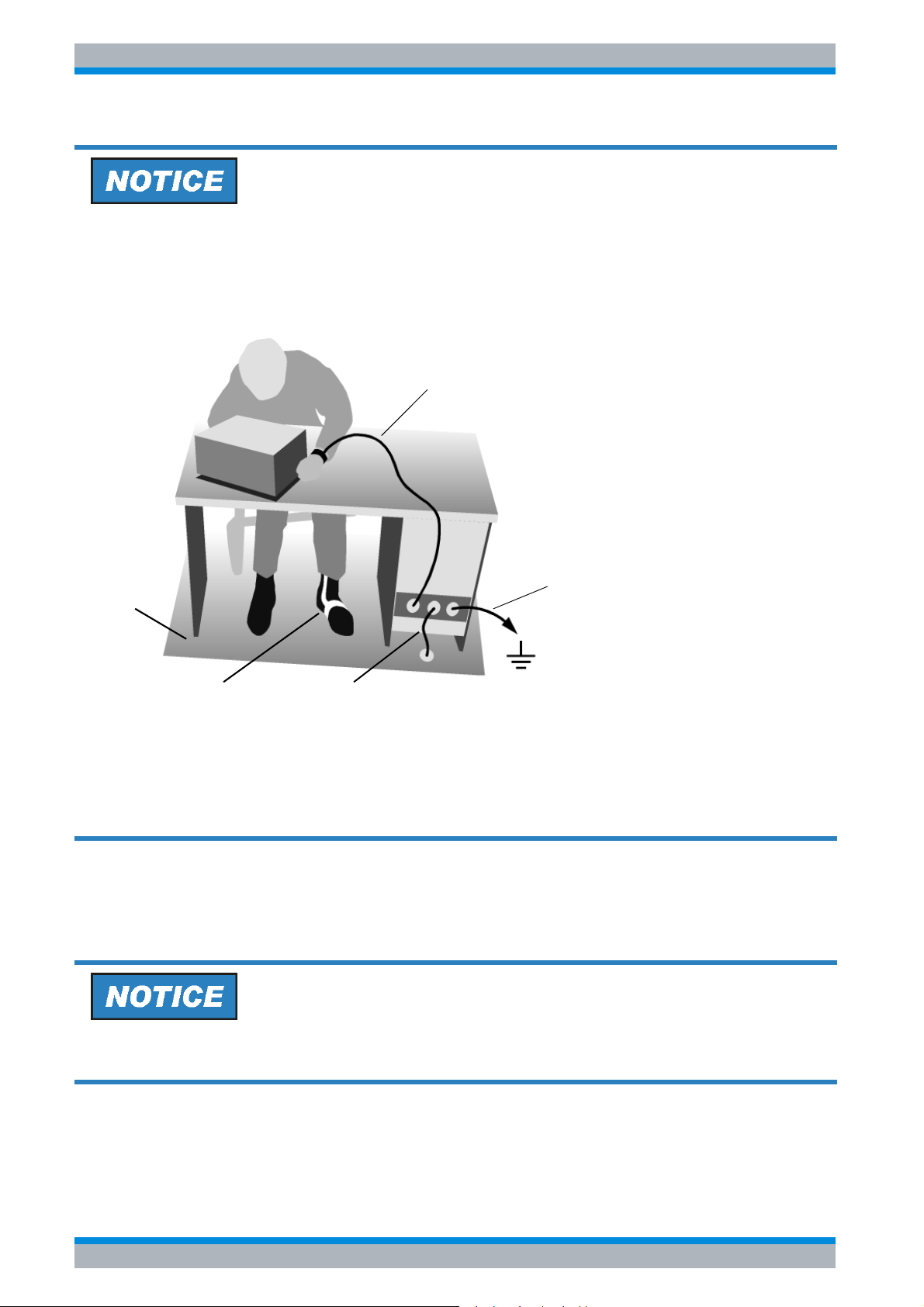
Risk of damaging electronic components
To avoid damage of electronic components, the operational site must be protected against
electrostatic discharge (ESD).
Wrist strap with cord
Building ground
Floor mat
Heel strap
Ground connection
of operational site
The following two methods of ESD protection may be used together or separately:
• Wrist strap with cord to ground connection
• Conductive floor mat and heel strap combination
2.1.3 Installation in a 19" Rack
The instrument can be installed in a 19" rack by using a rack adapter (see data sheet for order
number). The installation instructions are included with the adapter.
When the instrument is installed in a rack, make sure that the vents for air inflow on the side
panel and the air outlets on the rear panel are not obstructed.
2.4 Quick Start Guide 1164.6613.62 - 02
Page 35
R&S ESPI Preparing for Use
Preparing for Operation
2.1.4 Connecting the Instrument to the AC Power Supply
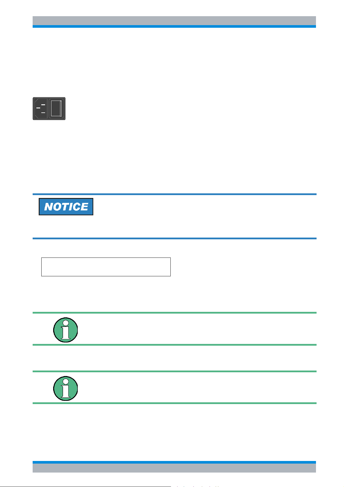
The R&S ESPI is equipped with a mechanism for detecting AC power voltage and
automatically sets itself to use the available AC power voltage (range: AC voltage 100 V to
240 V; 50 Hz to 400 Hz). The AC power connector is located on the rear panel of the
instrument.
➢ Connect the R&S ESPI to the AC power supply, using the power cable that
I
o
is supplied.
Since the instrument is assembled in line with the specifications for safety
AC power
connector
class EN61010, it may only be connected to an outlet that has a ground
contact.
2.1.5 Switching On the R&S ESPI
➢ Press the power switch on the real panel to change it to position I.
➢ Press the ON/STANDBY key on the front panel. The green LED will light up.
Do not switch off the instrument while it is booting.
Switching it off prematurely can lead to serious data changes on the instrument's hard disk.
After being switched on, the R&S ESPI displays the following information:
Rohde & Schwarz GmbH & Co. KG
Analyzer BIOS Vx.y
A self test of the computer hardware will be carried out. Windows XP then starts, and the
measurement screen will automatically appear with the settings that were present when the
instrument was last switched off.
If you want the instrument to automatically load different settings when
it is switched on, define the required configuration in the FILE -
STARTUP RECALL menu.
2.1.6 Functional Test
The functional test should only be performed when the operating
temperature is reached (approx. 15 minutes after the instrument is
switched on).
➢ Call self alignment with the CAL key, CAL TOTAL softkey. Once the system correction
values have been calculated successfully, the message Calibration Passed will appear.
Quick Start Guide 1164.6613.62 - 02 2.5
Page 36
R&S ESPI Preparing for Use
Preparing for Operation
➢ Start the self test with the SETUP key, SERVICE – SELFTEST softkeys. Once the
instrument modules have been checked successfully, the message Selftest Passed will
appear.
Once both steps have been completed successfully, the instrument will be ready for operation.
The self alignment does not need to be repeated every time the
instrument is switched on, because the instrument saves the values
and loads them during booting automatically. A self alignment is
recommended if the instrument is used at a temperature that differs
considerable (more than 10°C) from the temperature present at the last
self alignment.
The self test also does not need to be repeated every time the
instrument is switched on. It is necessary only when instrument
malfunction is suspected.
2.1.7 Switching Off the R&S ESPI
➢ Press the ON/STANDBY key on the front panel.
The R&S ESPI will store the current settings on the hard disk and then shut down the
software. Once the operation has been completed, the power supply unit will be switched
to STANDBY and the yellow LED will come on.
Shock hazard
In standby mode, the AC supply voltage is still present on the instrument.
➢ To completely disconnect the instrument from the AC power supply, change the power
switch on the rear panel to position O.
• The main power switch on the rear panel also interrupts the power
supply of the OCXO (optional) inside the instrument. When you
switch the instrument back on, be sure to adhere to the extended
warm-up phase.
• If you switch off the instrument by using the power switch or by
disconnecting the power supply connector, it is not possible to save
the current instrument settings on the hard disk. In this case, the last
settings that were stored on the hard disk will be loaded when you
switch the instrument back on.
2.6 Quick Start Guide 1164.6613.62 - 02
Page 37

R&S ESPI Preparing for Use
Instrument Drive Usage
2.1.8 Cleaning the Outside
The outside of the instrument is suitably cleaned using a soft, line-free dust cloth. Make sure
that the air vents are not obstructed.
Cleaning agents contain substances that may damage the instrument, e.g. solventcontaining cleaning agents may damage the front panel labeling or plastic parts.
Never use cleaning agents such as solvents (thinners, acetone, etc.), acids, bases, or other
substances.
2.2 Instrument Drive Usage
The harddisk space is divided in 3 logical drives.
C:
Contains the operating system Windows XP, printer driver, network driver,…
Other user programs, applications, driver should be stored/installed on drive C:.
D:
Contains instrument's firmware and related data sets (limit lines, transducers,...)
D:\user\config is the default location for customized instrument settings
D:\R_S\instr\temp is the default directory for hardcopy files.
Other user data should be stored on drive D:.
E:
Backup storage location for Windows XP. Here a copy of the operating system is saved.
This drive is used to restore Windows XP using "Analyzer Firmware Backup" function on
Power On. A copy of the currently installed update sets are located on this drive, too.
No additional data should be stored on this drive.
Quick Start Guide 1164.6613.62 - 02 2.7
Page 38

R&S ESPI Preparing for Use
Connecting External Devices
2.3 Connecting External Devices
2.3.1 Connecting an External Keyboard
Do not connect the keyboard unless the instrument is switched off (STANDBY). Otherwise,
proper functioning cannot be ensured due to interactions with the firmware.
An external PC keyboard can be connected to the USB interface on the front or the rear panel
of the R&S ESPI.
The keyboard simplifies instrument operation and the entry of comments, file names, etc.
Keyboards and mouse devices conform to USB Standards 1.1 or 2.0 are suitable for
connection to the USB interface.
After being connected, the keyboard is automatically detected. The default keyboard language
setting is US English. Special settings such as refresh rate, etc. can be made in the
Windows XP Start menu by selecting START - SETTINGS - CONTROL PANEL KEYBOARD.
International Keyboard Support
As of firmware version 4.3x, the following international keyboard drivers are supported.
• French Keyboards
• German Keyboards
• Italian Keyboards
• Portuguese Keyboards
• Spanish Keyboards
These drivers are already installed on the R&S ESPI, if it is shipped with firmware version 4.3x
or later. A separate installer file is available on the R&S ESPI internet site.
To change the keyboard driver language proceed as follows:
1. Start Windows Explorer
2. Start the installation procedure with double click onto the file FsxInternationalKey-
boards.msi.
3. Reboot the analyzer.
4. Now open the windows start menu by pressing the windows key or <CTRL> <ESC>.
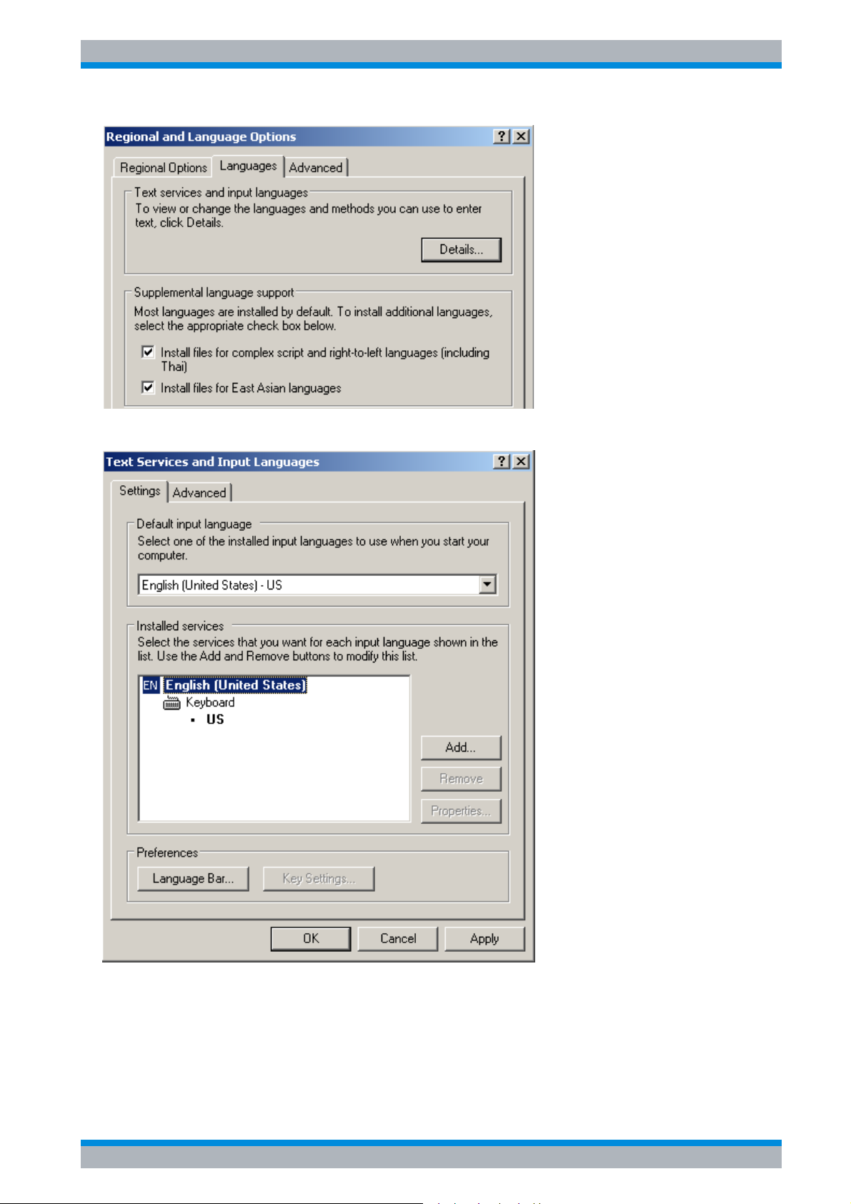
5. Select Settings - Control Panel - Regional and Language Options - Languages.
2.8 Quick Start Guide 1164.6613.62 - 02
Page 39
R&S ESPI Preparing for Use
Connecting External Devices
6. Select Details
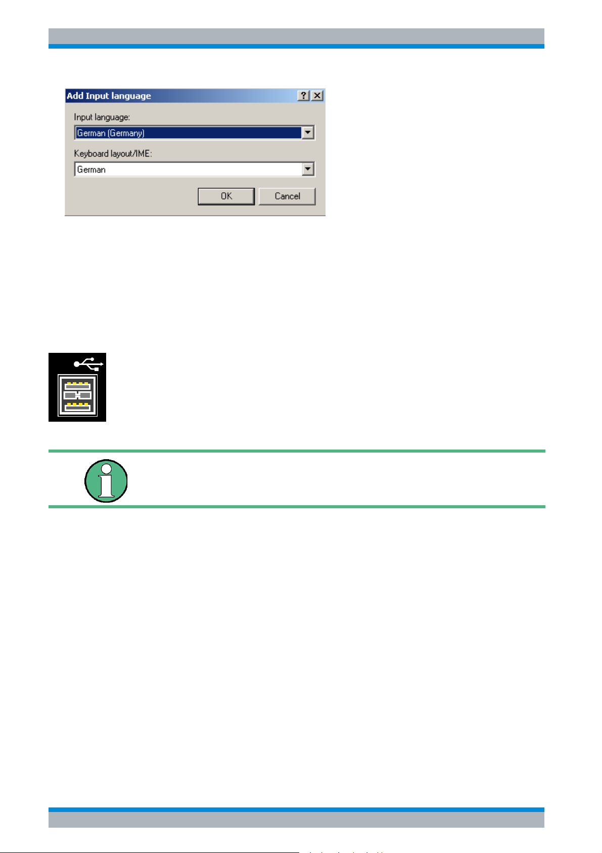
7. Select Add and choose one of the available languages.
Confirm your selection with OK.
Quick Start Guide 1164.6613.62 - 02 2.9
Page 40
R&S ESPI Preparing for Use
Connecting External Devices
8. Change the Default input language as you like in the Default Input Language pane and
close all open dialogs with OK.
9. Reboot the R&S ESPI
2.3.2 Connecting a Mouse
To simplify Windows XP operation, the R&S ESPI allows you to connect a mouse to one of
the USB interfaces on the front or rear panel.
USB
Mouse devices from Microsoft and Logitech are supported.
If you use a keyboard that contains a trackball for mouse operations,
connecting an external mouse in addition may lead to malfunctions.
After being connected, the mouse is automatically detected. Special settings such as mouse
cursor speed, etc. can be made in the Windows XP Start menu by selecting START -
SETTINGS - CONTROL PANEL - MOUSE.
2.10 Quick Start Guide 1164.6613.62 - 02
Page 41
R&S ESPI Preparing for Use
Connecting External Devices
2.3.3 Connecting an External Monitor
Do not connect a monitor unless the instrument is switched off (STANDBY). Otherwise, you
run the risk of damaging the monitor.
You can connect an external monitor at the MONITOR connector on the instrument's rear
panel.
MONITOR
After connecting the external monitor, restart the instrument to detect the monitor. The
measurement display will then appear on both the external screen and on the instrument. No
further settings are necessary.
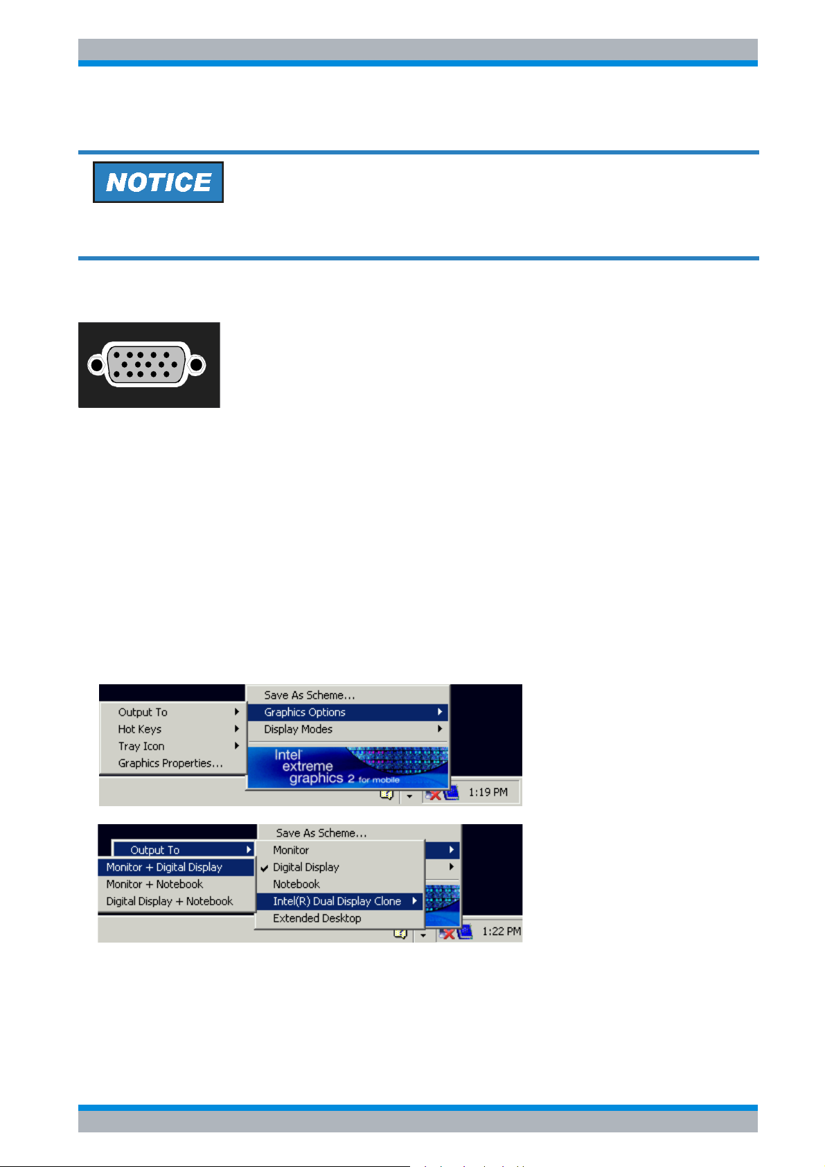
If the external monitor is not recognized by the instrument, you have to activate it. This
requires a mouse and an external keyboard (the connection is described in sections
“ Connecting a Mouse” on page 2.10 and “ Connecting an External Keyboard” on page 2.8).
➢ Make sure that the external monitor is connected.
➢ Press the CTRL+ESC key combination to display the taskbar.
➢ On the right side of the taskbar, click the monitor icon.
➢ Select Graphics Options - Output To - Intel(R) Dual Display Clone -
Monitor + Digital Display.
When the instrument is switched on later without a monitor, the activation of the external
monitor is reset.
Quick Start Guide 1164.6613.62 - 02 2.11
Page 42
R&S ESPI Preparing for Use
Connecting External Devices
2.3.4 Connecting a Printer
A printer can be connected during operation.
The R&S ESPI allows you to create two different printer configurations for printing out a
hardcopy of the screen and you can toggle between them by pressing a button. The DEVICES
table in the HCOPY menu lists the available installed printers.
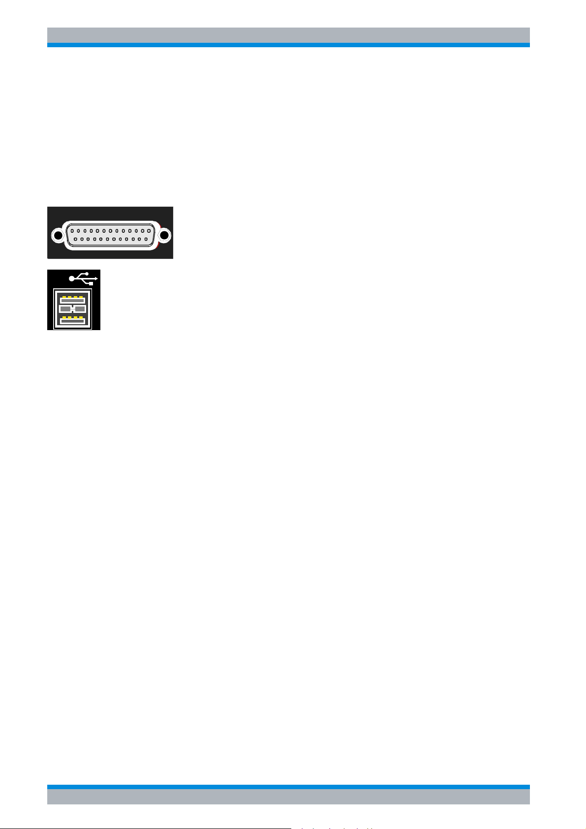
The LPT printer interface is located on the rear panel. Alternatively, one of the USB interfaces
on the front or rear panel can be used.
LPT
USB
2.3.5 Connecting USB Devices (e.g. a Power Meter)
The USB interface on the front and the rear panel of the R&S ESPI allows you to connect up
to 4 USB devices directly to the R&S ESPI. This number can be increased as necessary by
inserting USB hubs.
Due to the large number of available USB devices, there is almost no limit to the expansions
that are possible with the R&S ESPI. The following list shows various USB devices that can
be useful for the R&S ESPI:
• Power sensors of the R&S NRP-Zxx series
(require adapter cable R&S NRP-Z4)
• Memory stick for easy transfer of data to/from a PC
(e.g. firmware updates)
• CD-ROM drives for easy installation of firmware applications
• PC keyboard for entering comments, file names, etc.
• Mouse for easy operation of Windows XP dialog boxes
• Printer for printing out measurement results
• Modem for remote control of the R&S ESPI over large distances
Installing USB devices is easy under Windows XP, because all USB devices are plug&play.
All USB devices can be connected to or disconnected from the R&S ESPI during operation.
After a device is connected to the USB interface of the R&S ESPI, Windows XP automatically
searches for a suitable device driver.
If Windows XP does not find a suitable driver, it will prompt you to specify a directory that
contains the driver software. If the driver software is on a CD, connect a USB CD-ROM drive
to the R&S ESPI before proceeding.
2.12 Quick Start Guide 1164.6613.62 - 02
Page 43
R&S ESPI Preparing for Use
Connecting External Devices
When a USB device is subsequently disconnected from the R&S ESPI, Windows XP
immediately detects the change in hardware configuration and deactivates the corresponding
driver.
Example:
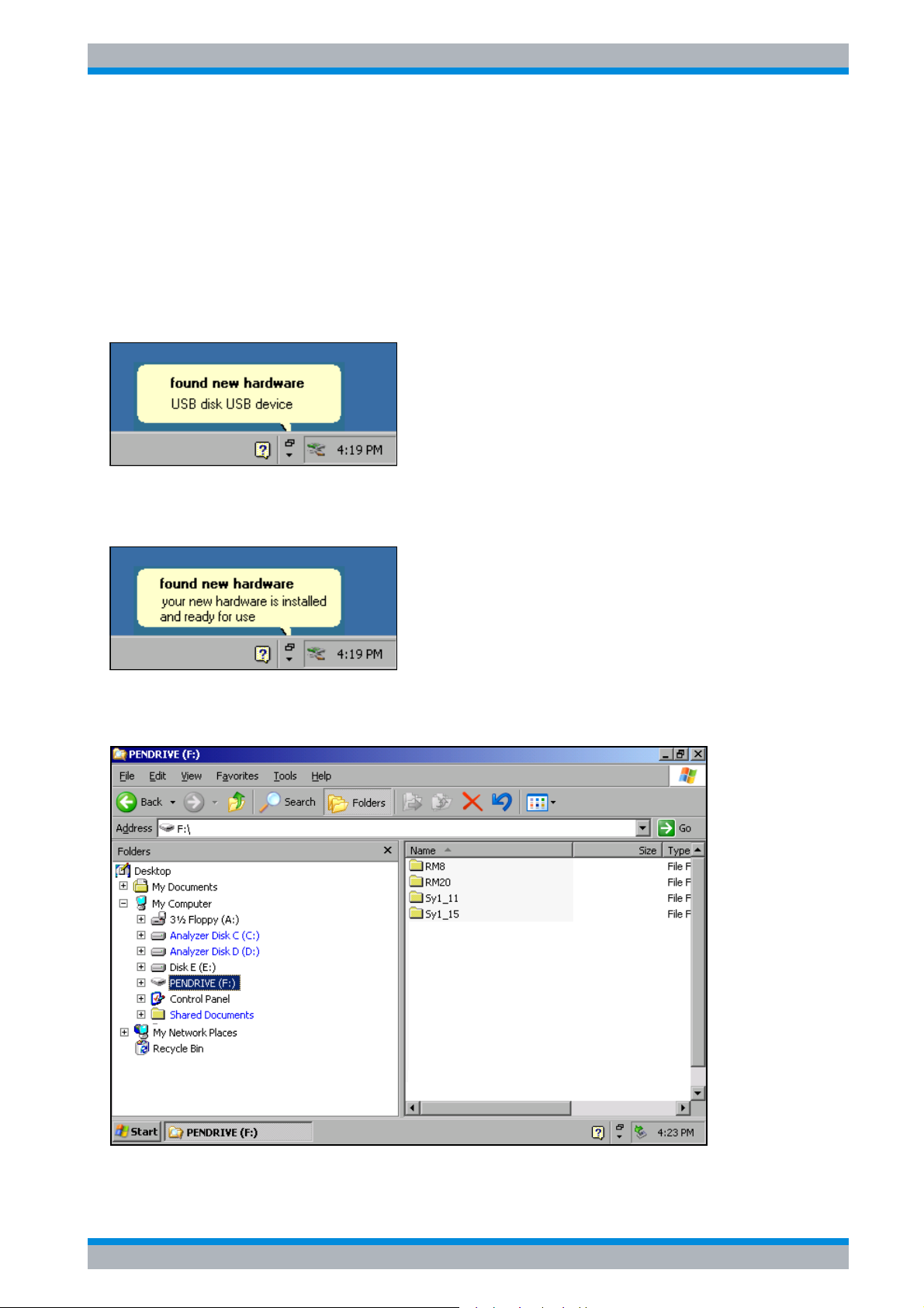
Connect a memory stick to the R&S ESPI:
1. When you connect the pendrive at the USB interface, Windows XP detects the new
hardware:
2. Windows XP installs the corresponding driver.
If installation is successful, Windows XP informs you that the device is ready to use:
The memory stick is made available as a new drive and is displayed in the Windows
Explorer:
The memory stick can be used like a normal drive to load or store data.
Quick Start Guide 1164.6613.62 - 02 2.13
Page 44
R&S ESPI Preparing for Use
Connecting External Devices
3. If you no longer need the memory stick or if you want to transfer files to another computer,
simply disconnect the memory stick. Windows XP will automatically deactivate the driver. If
the drive is still selected in Explorer, an error message will appear indicating that the drive
is no longer available.
2.3.6 Connecting External Generators
The External Generator Control option (R&S FSP-B10) allows you to operate a number of
commercially available generators as a tracking generator on the R&S ESPI. When suitable
generators are used, the R&S ESPI thus allows scalar network analysis to be performed also
outside the frequency range of the internal tracking generator. Appendix “External Generator
Control” provides a list of generators supported by the option R&S FSP-B10.
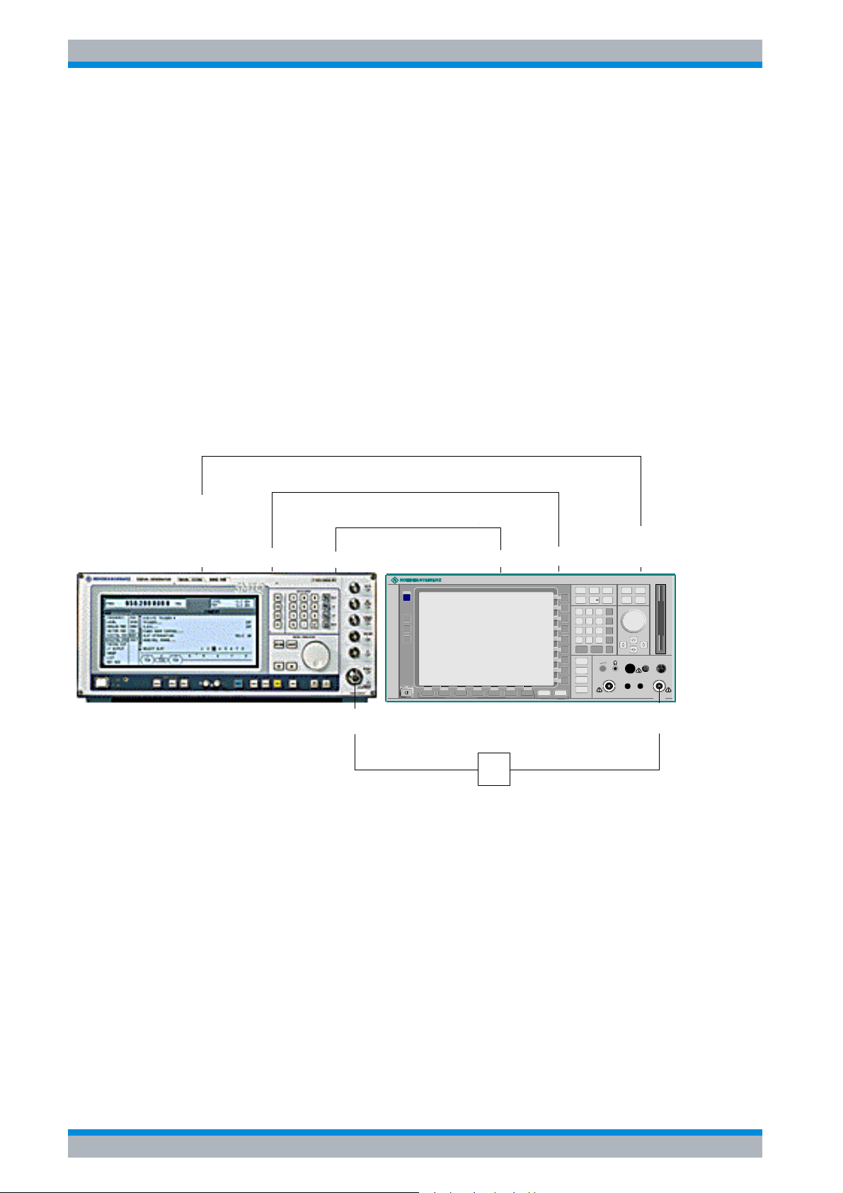
The following figure shows the test setup:
TTL (optional)
TTL (optional)
GPIB
AUX /
AUX /
TRIGGER
TRIGGER
BLANK
BLANK
MARKER
MARKER
IEC-BUS
GEN OUTPUT
Reference Frequency
Reference Frequency
REF
PRESET
CAL
SETUP
HCOPY
REF IN
SPECTRUM ANALYZER 9kHz . . . 3GHz..FSP
DUT
DUT
.
IEC2
PREV
NEXT
FREQ
SPAN
MKR
MKR
789
45
12
0
.
ESC
ENTER
CANCEL
TRACE
LINES
DISP
FILE
6
3
-
GEN OUTPUT 50
MAX 0V DC
AUX
CONTROL
1093.4495.03
AMPT
BW SWEEP
MKR
MEAS TRIG
FCTN
GHz
s
V
-dBm
MHz
ms
mV
dBm
µs
kHz
µV
dB
ns
Hz
nV
dB..
BACK
AF OUTPUT
KEYBOARDPROBE POWER
Ω
EXT MIXER
RF INPUT
MAX +30 dBm / 50V DC
MADE IN GERMANY
RF INPUT
50
Ω
The generator is controlled via the – optional – second GPIB interface of the R&S ESPI
(= IEC2, supplied together with the option). With some Rohde & Schwarz generators, it is also
controlled via the TTL synchronization interface that is contained in the AUX CONTROL
interface of the R&S ESPI.
2.14 Quick Start Guide 1164.6613.62 - 02
Page 45

R&S ESPI Preparing for Use
Connecting External Devices
• Using the TTL interface allows you to attain significantly higher
speeds than possible with a pure GPIB control, because the
frequency switching mechanism of the R&S ESPI is directly coupled
to the frequency switching mechanism of the generator.
• To increase measurement accuracy, use a shared reference
frequency to operate the R&S ESPI and the generator. If no
independent 10 MHz reference frequency is available, connect the
reference output of the generator to the reference input of the R&S
ESPI and use SETUP – REFERENCE EXT to configure the R&S
ESPI to implement the external reference.
2.3.6.1 Connecting the R&S ESPI to the Generator
To couple the frequency setting and level setting of the generator to the R&S ESPI, set up the
following connections:
1. Connect the GPIB interface of the generator to the IEC2 connector on the rear panel of the
R&S ESPI.
2. (Optional:) Connect the TTL interface of the generator and the R&S ESPI.
➢ Alternative 1 (R&S SMR, R&S SMU):
Connect the AUX CONTROL connector of the R&S ESPI to the corresponding AUX
connector on the rear panel of the generator (the connection cable is supplied together
with the option R&S FSP-B10).
➢ Alternative 2 (R&S SME, R&S SMP, R&S SMIQ):
Connect the AUX CONTROL connector of the R&S ESPI to the TRIGGER, MARKER
and BLANK connectors on the rear panel of the generator (the connection cable is also
supplied together with the option R&S FSP-B10). Note the labelling on the TRIGGER,
MARKER and BLANK lines.
➢ Alternative 3 (R&S SML, R&S SMG/SMGU, R&S SMH/SMHU, R&S SMX/SMY,
generators from other manufacturers):
No TTL connection possible.
The generator type determines which one of the possible connections is suitable for the
generator. For more information, refer to the Operating Manual for the generator.
3. Connect the reference frequency output of the generator to the reference frequency input
(REF IN) of the R&S ESPI.
or
Connect the reference frequency inputs of the two instruments to an external frequency
standard.
2.3.6.2 Configuring the Generator on the R&S ESPI
To configure the generator, change into the NETWORK mode:
➢ Press the SPECTRUM hotkey to change to the analyzer mode.
➢ Press the NETWORK hotkey located in the hotkey bar at the lower edge of the screen.
Quick Start Guide 1164.6613.62 - 02 2.15
Page 46
R&S ESPI Preparing for Use
Connecting External Devices
Perform the following steps:
1. Press the EXT SOURCE softkey. The submenu for configuring generators will open
2. Select and configure the generator:
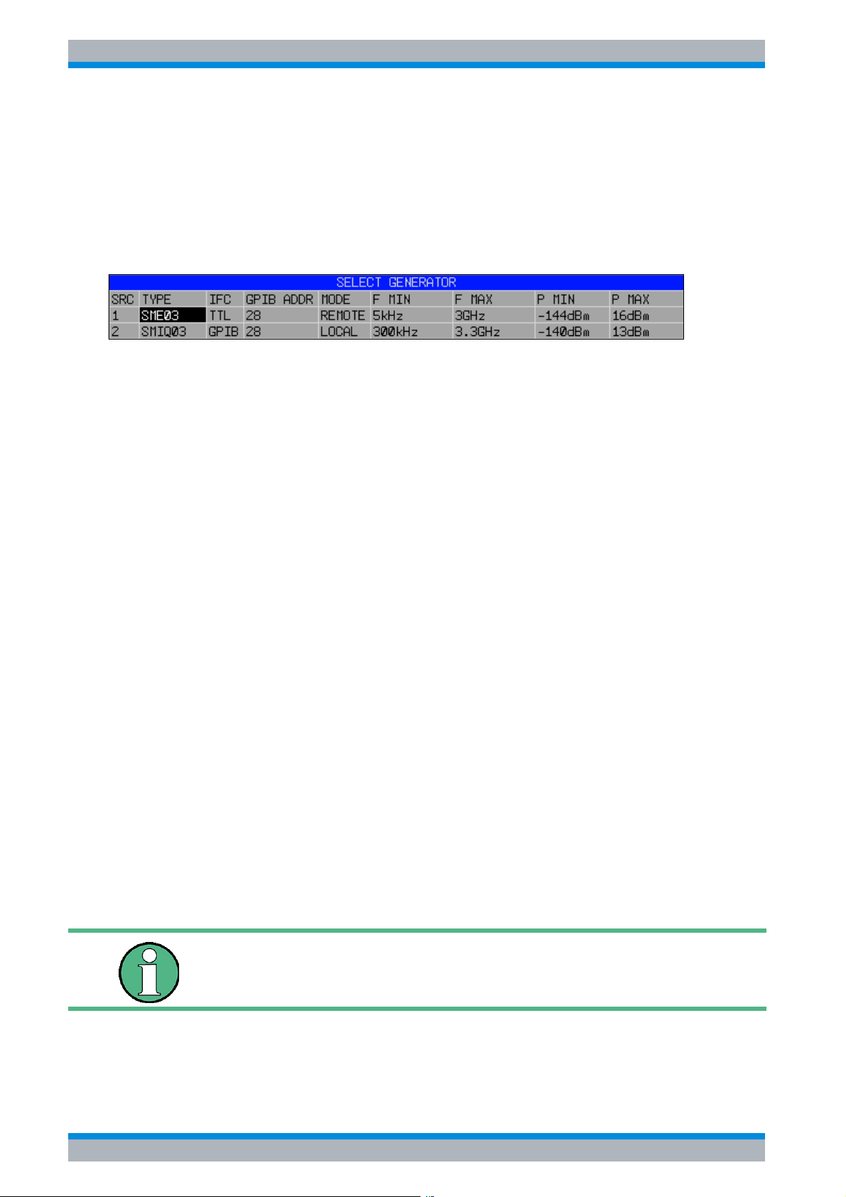
➢ Press the SELECT GENERATOR softkey.
The table containing the generator settings will open. The selection bar will be located in
the row SRC 1 under the column TYPE.
➢ Press the ENTER key.
The list of available generators will open.
➢ Using the rotary knob, select the desired generator and activate ENTER by pressing the
rotary knob.
The generator list will close, and the selected generator will then appear in the SELECT
GENERATOR table. Simultaneously, the limits for frequency and output power which
you can set on the generator will appear in the F MIN, F MAX, P MIN and P MAX fields.
➢ Using the Ur key, move the selection bar to the IFC column and press the ENTER key.
The list of available control interfaces will appear.
➢ If the TTL interfaces from the R&S ESPI and generator are connected, select TTL by
using the rotary knob and then activate it by pressing the rotary knob.
➢ If no TTL interface is provided or if the TTL interfaces are not connected, select GPIB by
using the rotary knob and then activate it by pressing the rotary knob.
➢ Using the Ur key, move the selection bar to the GPIB ADDR column and press the
ENTER key.
The entry field for the GPIB address of the generator will open.
➢ Enter the GPIB address of the generator and confirm with ENTER.
The specified address will be added to the table.
3. Select the reference frequency for the generator:
➢ If you want to operate the generator using its internal reference, change the GEN REF
softkey to the state INT.
➢ If you want to operate the generator using an external reference, change the GEN REF
softkey to the state EXT.
This concludes the procedure for defining the default setting for the generator.
A second generator configuration can be inserted in advance by
repeating the settings in the line SRC 2. This makes it easy to switch
from one generator type to another.
2.16 Quick Start Guide 1164.6613.62 - 02
Page 47
R&S ESPI Preparing for Use
Connecting External Devices
2.3.6.3 Activating the Generator Configuration and Setting the Output Level
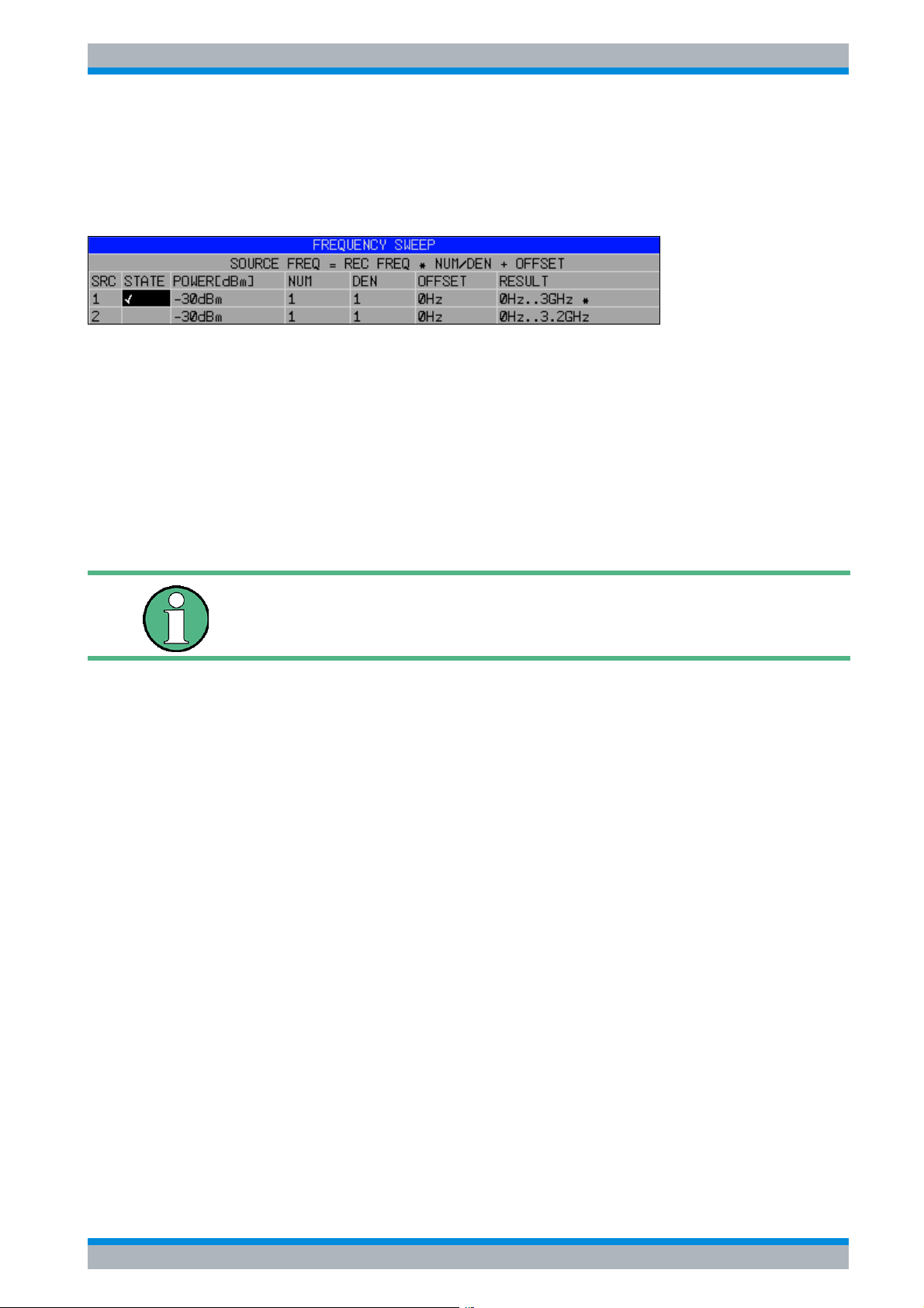
To select the active generator configuration, press the FREQUENCY SWEEP softkey. The
FREQUENCY SWEEP table will open, and the selection bar will be located under the STATE
column in the SRC 1 row.
➢ If you want to use the SRC 1 generator configuration, insert a checkmark in the field by
pressing the ENTER key.
➢ If you want to use the SRC 2 generator configuration, move the selection bar to the lower
line of the table by using the Ud key. Then activate the generator configuration by pressing
the ENTER key and set the checkmark in line 2 under the STATE column.
➢ Using the Ur key, move the selection bar to the POWER [dBm] column and press the
ENTER key.
➢ Enter the desired output power and confirm with the dBm key. The power you entered will
appear in the table.
You can also change the output power of the generator by using the
SOURCE POWER softkey located in the NETWORK menu.
The remaining columns of the table are used to configure frequency-converting
measurements. For more information, refer to the Operating Manual, section "External
Generator Control - Option R&S FSP-B10".
This concludes the procedure for configuring the generator.
2.3.6.4 Using an External Generator as a Tracking Generator
To activate the external generator as a tracking generator, do the following:
➢ Switch on the external generator.
➢ Press the NETWORK hotkey on the R&S ESPI.
➢ Press the EXT SOURCE softkey.
Tracking generator operation using an external generator will be activated. The external
generator will switch to remote control and can be used like an internal tracking generator. For
more information about measurements with an external tracking generator, refer to the
Operating Manual, section "External Generator Control - Option R&S FSP-B10".
Switching off the tracking generator:
➢ Press the NETWORK hotkey on the R&S ESPI.
➢ Press the EXT SOURCE softkey.
➢ Change the EXT SRC softkey to OFF by pressing it.
Quick Start Guide 1164.6613.62 - 02 2.17
Page 48
R&S ESPI Preparing for Use
Setup
When you switch off tracking generator operation using an external
generator, control on the IEC2 is automatically released and the
generator is returned to LOCAL mode.
2.4 Setup
2.4.1 Selecting the Frequency Reference
You can switch the reference signal for frequency processing of the R&S ESPI between the
internal reference and an external reference signal at 10 MHz as follows:
➢ Press the SETUP key.
The SETUP menu will open.
➢ Press the REFERENCE INT/EXT softkey until it is in the desired state.
If the reference signal is missing when switchover to the external
reference occurs, EXREF is displayed after a few moments, indicating
that synchronization has not taken place.
When switchover to an internal reference occurs, note that the external
reference signal is removed in order to avoid any interactions with the
internal reference signal.
IEC bus command: ROSC:SOUR INT
2.4.2 Setting the Date and Time
➢ Press the SETUP key.
The SETUP menu will open.
➢ Press the GENERAL SETUP softkey.
The submenu with general settings will open.
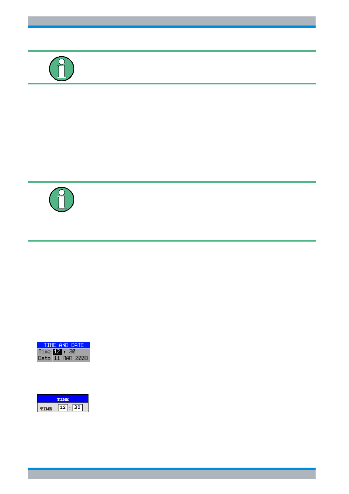
The TIME+DATE softkey activates the TIME AND DATE table for entering the time and
date for the internal real-time clock.
Entering the time
Hours and minutes can be entered independently of each other in the entry field:
IEC bus command: SYST:TIME 12,30
2.18 Quick Start Guide 1164.6613.62 - 02
Page 49
R&S ESPI Preparing for Use
Setup
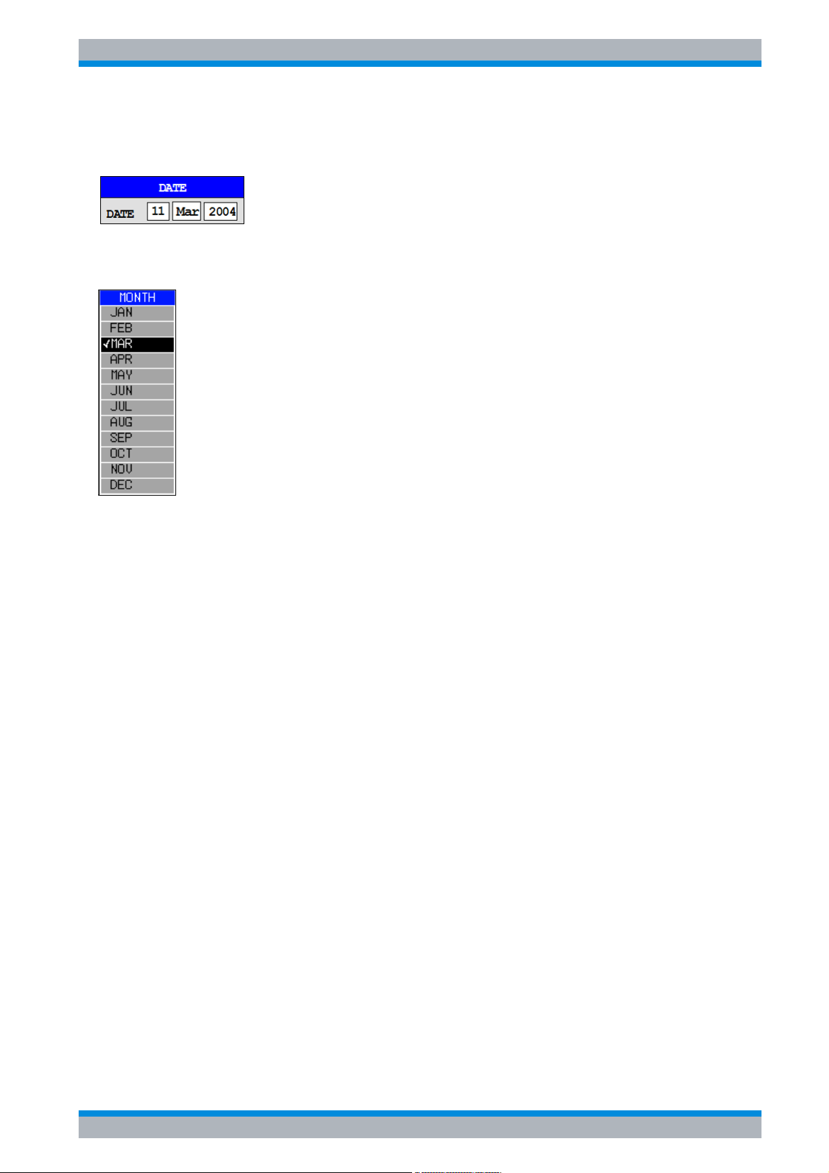
Entering the date
The day, month and year can be entered independently of each other in the entry field:
To select the month, use the units key to open a list containing the month names. You can
then select the month from the list.
IEC bus command: SYST:DATE 2002,03,11
2.4.3 Setting the GPIB Interface
➢ Press the SETUP key.
The SETUP menu will open.
➢ Press the GENERAL SETUP softkey.
The submenu with general settings will open.
➢ Press the GPIB softkey.
The submenu for setting the parameters of the remote control interface will open.
2.4.3.1 GPIB Address
➢ Press the GPIB ADDRESS softkey.
The entry field for the GPIB address will open.
The setting range is from 0 to 30. The default address is 20 if SCPI is selected as the GPIB
language or 18 if an 85xx emulation is selected.
IEC bus command: SYST:COMM:GPIB:ADDR 20
Quick Start Guide 1164.6613.62 - 02 2.19
Page 50
R&S ESPI Preparing for Use
Setup
2.4.3.2 GPIB Language
➢ Press the GPIB LANGUAGE softkey.
The list of available remote control languages will open.
The following languages are available:
•SCPI
• HP mode:
8560E, 8561E, 8562E, 8563E, 8564E, 8565E
8566A, 8566B, 8568A, 8568A_DC, 8568B, 8568B_DC, 71100C, 71200C, 71209A
8591E, 8594E
If entries of the HP mode are selected, the command recognition uses
syntax rules which are different from syntax rules of the SCPI mode.
Correspondingly, proper detection of SCPI commands is not ensured
in this mode.
For 8566A/B, 8568A/B and 8594E, command sets A and B are
available. Command sets A and B differ in the rules regarding the
command structure.
Selecting a language different from "SCPI" will set the GPIB address to
18 if it was 20 before.
Start / stop frequency, reference level and # of sweep points will be
adapted to the selected instrument model.
8568A_DC and 8568B_DC are using DC input coupling as default if it
is supported by the instrument.
The HP model 8591E is compatible to HP model 8594E, the HP models
71100C, 71200C, and 71209A are compatible to HP models 8566A/B.
71100C, 71200C, 71209A, 856xA/B, 856xE, 8591E, 8594E:
• The instrument will perform a preset.
The following instrument settings will then be changed:
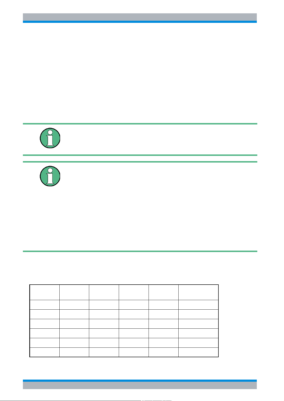
Model # of Trace
Points
8560E 601 0 Hz 2.9 GHz 0 dBm AC
Start Freq. Stop Freq. Ref Level Input Coupling
8561E 601 0 Hz 6.5 GHz 0 dBm AC
8562E 601 0 Hz 13.2 GHz 0 dBm AC
8563E 601 0 Hz 26.5 GHz 0 dBm AC
8564E 601 0 Hz 40 GHz 0 dBm AC
8565E 601 0 Hz 50 GHz 0 dBm AC
2.20 Quick Start Guide 1164.6613.62 - 02
Page 51
R&S ESPI Preparing for Use
Setup
Model # of Trace
Points
8566A/B 1001 2 GHz 22 GHz 0 dBm AC (R&S ESPI)
8568A/B 1001 0 Hz 1.5 GHz 0 dBm AC
8591E 401 0 Hz 3 GHz 0 dBm AC
8594E 401 0 Hz 3 GHz 0 dBm AC
71100C 1001 2 GHz 22 GHz 0 dBm AC (R&S ESPI)
71200C 1001 2 GHz 22 GHz 0 dBm AC (R&S ESPI)
71209A 1001 2 GHz 22 GHz 0 dBm AC (R&S ESPI)
Start Freq. Stop Freq. Ref Level Input Coupling
Note regarding the selection of 856x for the R&S ESPI:
• The # of trace points is not switched over until the state changes to
REMOTE. In the case of switchover to manual operation (LOCAL
key), the number of sweep points is always changed to 501.
• If necessary, the stop frequency specified in the table is restricted to
the corresponding frequency range of the R&S ESPI.
IEC bus command: SYST:LANG "SCPI" | "8560E" |
"8561E" | "8562E" | "8563E" |
"8564E" | "8565E" | "8566A" |
"8566B" | "8568A" | "8568A_DC" |
"8568B" | "8568B_DC" | "8591E" |
"8594E" | "71100C" | "71200C" |
"71209A"
2.4.3.3 ID Response String
➢ The ID STRING FACTORY softkey selects the default response to the command *IDN?.
IEC bus command: --
➢ The ID STRING USER softkey opens the editor for entering a user-defined response to the
command *IDN?. The max. length of the output string is 36 characters.
IEC bus command: --
2.4.4 Setting the Screen Colors
➢ Press the DISP key.
The DISPLAY menu will open.
➢ Press the CONFIG DISPLAY softkey.
The submenu for configuring the screen will open.
Quick Start Guide 1164.6613.62 - 02 2.21
Page 52

R&S ESPI Preparing for Use
Setup
➢ The DEFAULT COLORS 1 and 2 softkeys set the default setting for brightness, tint and
color saturation of all screen objects. The color schemes are selected in such a manner that
all screen elements will be optimally visible regardless whether viewed from above or
below. In the instrument's default setting, DEFAULT COLORS 1 is active.
IEC bus command: DISP:CMAP:DEF1
DISP:CMAP:DEF2
The procedure for setting screen colors and brightness is as follows:
➢ Press the NEXT key.
The side menu for changing the screen colors will open.
The SELECT OBJECT softkey activates the selection of screen elements for which the
color setting needs to be changed. Once this selection is made, the PREDEFINED
COLORS, BRIGHTNESS, TINT and SATURATION softkeys can be used to change the
overall color or the brightness, tint and color saturation of the selected element.
SELECT D ISP LAY OBJECT
Background
Grid
Function field + status field + data entry text
Function field LED on
Function field LED warn
Enhancement label text
Status field background
Trace 1
Trace 2
Trace 3
Marker
Lines
The BRIGHTNESS softkey activates entry of the brightness of the selected graphics
element.
The entry value is between 0% and 100%.
IEC bus command: DISP:CMAP5:HSL <hue>,<sat>,<lum>
The TINT softkey activates entry of the tint for the selected graphics element. The percent
value that is entered refers to a continuous color spectrum that ranges from red (0%) to blue
(100%).
IEC bus command: DISP:CMAP5:HSL <hue>,<sat>,<lum>
2.22 Quick Start Guide 1164.6613.62 - 02
Page 53
R&S ESPI Preparing for Use
Setup
The SATURATION softkey activates entry of the color saturation of the selected element.
The entry value is between 0% and 100%.
IEC bus command: DISP:CMAP5:HSL <hue>,<sat>,<lum>
The PREDEFINED COLORS softkey opens a list for selecting predefined colors for the
screen objects:
COLOR
BLACK
BLUE
BROWN
GREEN
CYAN
RED
MAGENTA
YELLOW
IEC bus command: DISP:CMAP1 ... 26:PDEF <color>
2.4.5 Automatically Switching Off the Internal Screen
The R&S ESPI provides a feature for automatically switching off the screen after a userdefined period of time. The background lighting will be disabled if no entries are made from
the front panel after the selected response time (key, softkey or hardkey and rotary knob).
To activate automatic switch-off:
➢ Press the DISP key.
➢ Press the CONFIG DISPLAY softkey.
➢ Press the DISPLAY PWR SAVE softkey.
The softkey will have a color background, indicating that the power save mode
is active. At the same time, the input window for the response time will open.
➢ Enter the desired response time in minutes and confirm the entry with the ENTER key.
The screen will be disabled (turn dark) after the selected period of time.
To deactivate automatic switch-off:
➢ Press the DISP key.
➢ Press the CONFIG DISPLAY softkey.
➢ Press the DISPLAY PWR SAVE softkey twice.
The color background of the softkey will disappear.
The power save mode is now switched off.
Quick Start Guide 1164.6613.62 - 02 2.23
Page 54
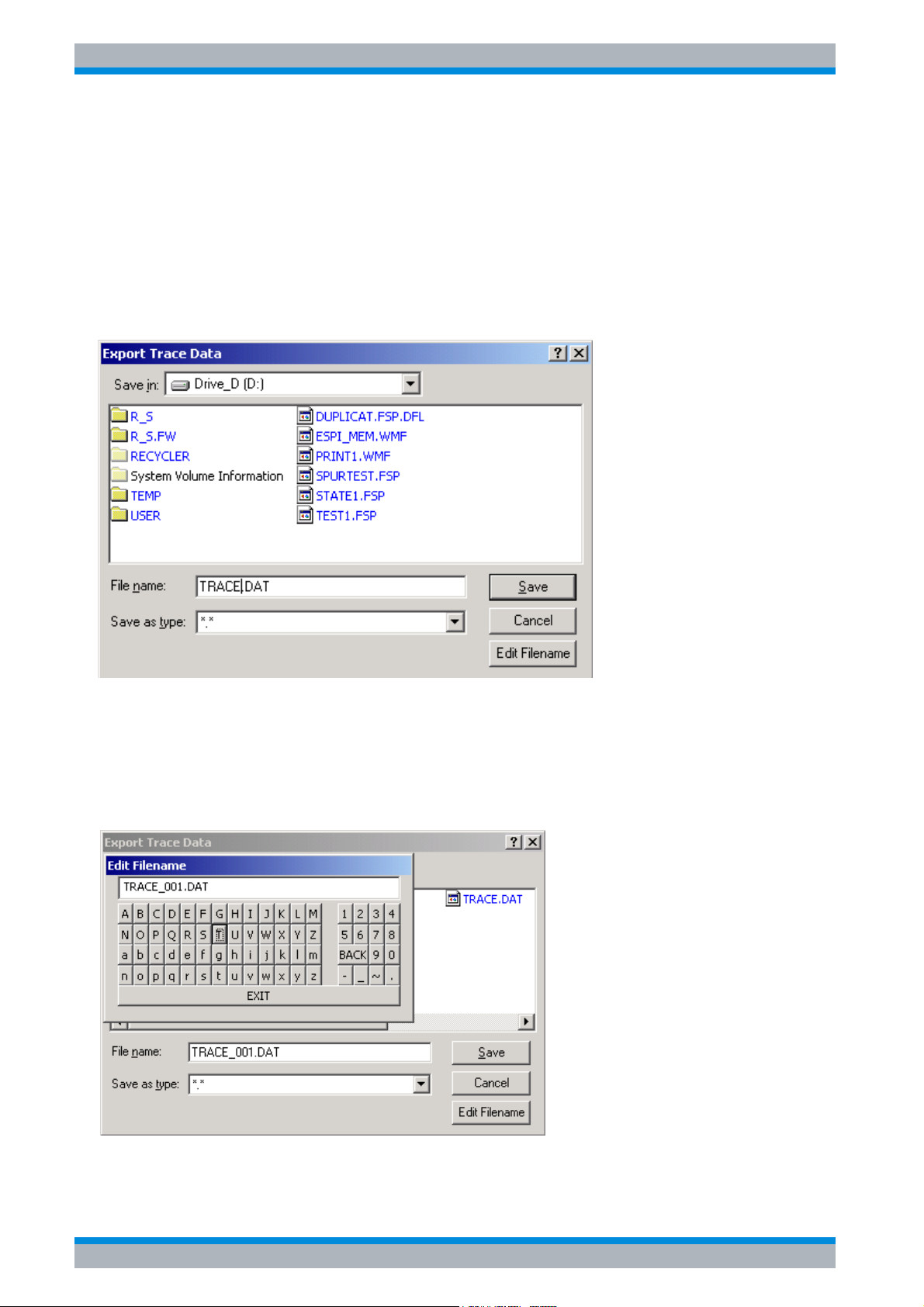
R&S ESPI Preparing for Use
Setup
2.4.6 File and Path Selection Using the Front Panel Keys
As of firmware version 4.3x the base system firmware supports new dialog boxes to select a
folder and/or a file, e.g. for trace export.
The following section describes the usage of the instrument's front panel keys using TRACE
EXPORT as an example.
➢ Press the TRACE key and then the NEXT softkey.
➢ Press the ASCII FILE EXPORT softkey to open the corresponding dialog box.
The focus is on the File Name field so you can directly edit the file name using the numeric
keys, the cursor keys or the BACK key.
You can also use alphanumeric characters in the file name.
➢ To enter alphanumeric characters, select the EDIT FILENAME button. Confirm the
selection with the ENTER key to open an online keyboard.
Select the characters with the rotary knob or the cursor keys and confirm with the ENTER
key.
2.24 Quick Start Guide 1164.6613.62 - 02
Page 55
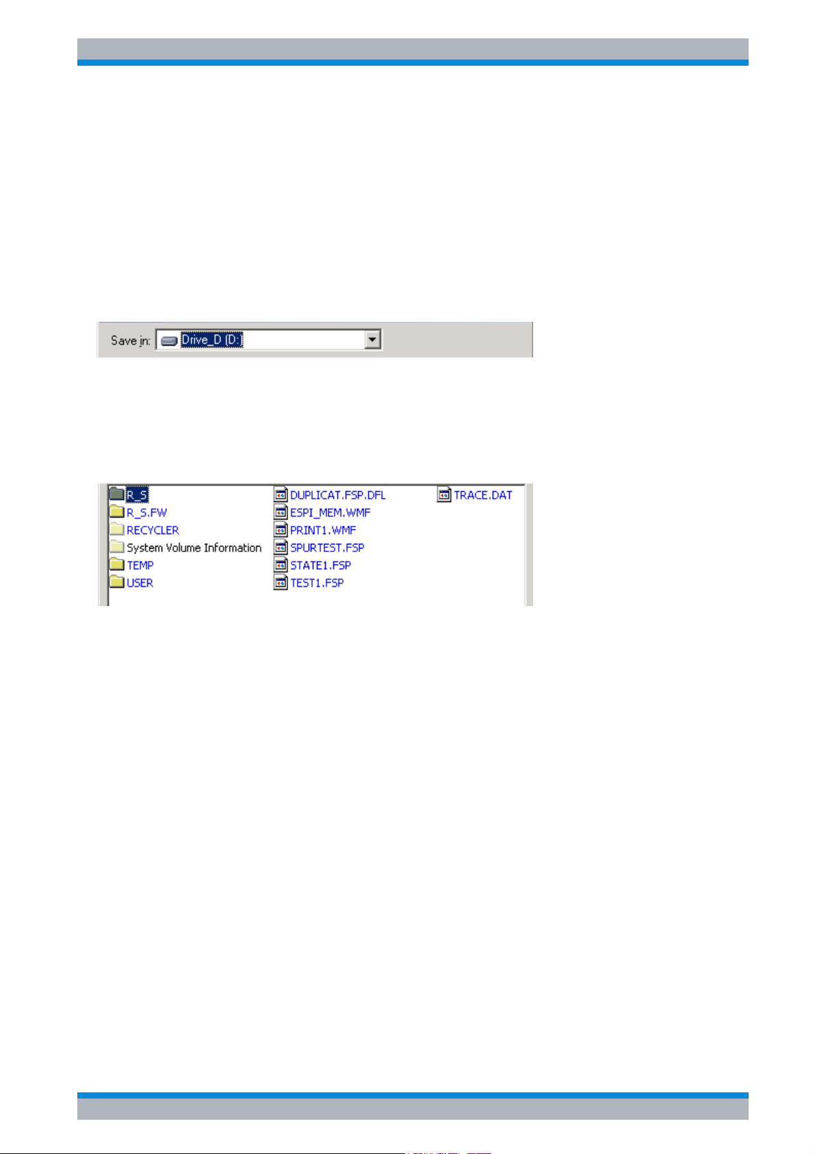
R&S ESPI Preparing for Use
Setup
➢ Drive usage is checked according to the following rules:
• first, the R&S ESPI checks for a connected memory stick
• if a memory stick is not recognized, then the R&S ESPI uses the floppy drive
• if the R&S ESPI doesn’t recognize a floppy drive or there is no floppy in the drive, the
R&S ESPI uses the internal hard disk.
Note that the path and file name are reset to their default values after an instrument
PRESET.
➢ Change the drive by moving the rotary knob until the focus is on the Save In field.
➢ Press the CURSOR RIGHT key to open the dropdown menu and select the drive you want
to save the file to with the CURSOR UP and CURSOR DOWN keys. Confirm your selection
by pressing the ENTER key.
➢ Select a subfolder by moving the rotary knob until the file / subfolder list is in focus. The
selected file or subfolder in focus is framed by dotted line.
➢ Use the CURSOR UP or CURSOR DOWN keys to select a specific folder or file. To change
the path or select a file, confirm your selection with the ENTER key.
Note that the R&S ESPI overwrites existing files with the new data.
Quick Start Guide 1164.6613.62 - 02 2.25
Page 56
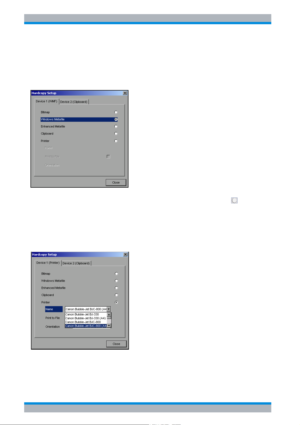
R&S ESPI Preparing for Use
Setup
2.4.7 Selecting and Configuring Printers
➢ Press the HCOPY key.
The HARDCOPY menu will open.
➢ Press the DEVICE SETUP softkey.
The dialog box for selecting the file format and printer will open:
➢ You can select a connected printer (including a pre-configured network printer) by
positioning the selection bar on the Printer entry by turning the rotary knob and then
confirming the selection by pressing the rotary knob or the ENTER key.
After you confirm the selection, the entries Name, Print to File and Orientation will be made
available and can also be accessed with the rotary knob.
➢ To select the printer type, open the selection list by pressing the rotary knob or the ENTER
key after you access the Name field.
From the selection list, you can now select the printer you want (in the example, this is
Cannon Bubble-Jet BJC800 (A4)) by using the rotary knob again and then confirming your
selection with ENTER or by pressing the rotary knob. The selection list will then disappear
and the entry cursor will return to the Name field.
2.26 Quick Start Guide 1164.6613.62 - 02
Page 57
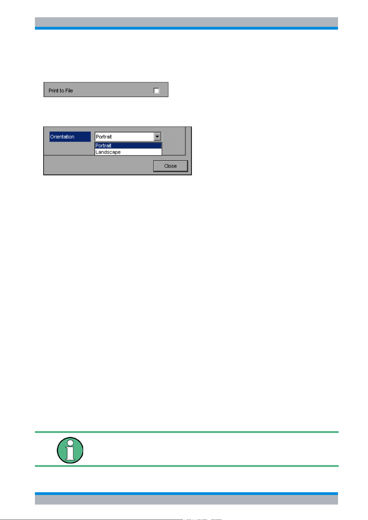
R&S ESPI Preparing for Use
Setup
➢ You can also redirect the output to a file rather than to a printer. To do this, select the field
Print to File by using the rotary knob and then mark the appropriate selection box or cancel
the marking by pressing either the rotary knob or the ENTER key:
➢ You can select orientation for paper printout by using the Orientation field. To open the
selection list, press the rotary knob or ENTER:
From the selection list, you can now select the orientation you want (Portrait in the
preceding figure) by using the rotary knob again and then confirm with ENTER or by
pressing the rotary knob. The selection list will then close and the entry cursor will return to
the Orientation field.
You can now close the dialog box by pressing the ESC key or by selecting and confirming
the Close button.
2.4.7.1 Selecting Alternative Printer Configurations
The R&S ESPI can support two independent hardcopy settings. This allows you to quickly
switch between output to a file and a printer.
➢ To make a selection, use the DEVICE 1 / 2 softkey, which simultaneously shows the
associated setting when the Hardcopy Setup dialog box is open.
IEC bus command: -
2.4.7.2 Selecting Printer Colors
➢ The COLORS softkey opens the submenu for selecting the colors for the printout. To make
it easier for you to select colors, the selected hardcopy color combination is displayed on
screen when you access the menu. When you exit the menu, the system switches back to
the previous color combination.
➢ The COLOR ON OFF softkey switches from color output to black-and-white printout. In this
case, all background colors will be printed out in white and all color lines in black. This
allows you to improve contrast on the printout. The basic setting is COLOR ON.
IEC bus command: HCOP:DEV:COL ON
➢ The SCREEN COLORS softkey selects the current screen colors for the printout.
The background will always be printed out in white and the grid in black.
Quick Start Guide 1164.6613.62 - 02 2.27
Page 58
R&S ESPI Preparing for Use
Setup
IEC bus command: HCOP:CMAP:DEF1
➢ The OPTIMIZED COLORS softkey selects an optimized color setting for the printout in
order to improve color clarity on the printout.
With this selection, trace 1 will be printed out in blue, trace 2 in black, trace 3 in green and
the markers in turquoise.
The other colors correspond to the screen colors of the DISP – CONFIG DISPLAY -
DEFAULT COLORS 1 softkey.
The background will always be printed out in white and the grid in black.
IEC bus command: HCOP:CMAP:DEF2
➢ The USER DEFINED softkey opens a submenu for user-defined color selection (see the
USER DEFINED COLORS submenu).
The procedure for making the settings is similar to that for setting the screen colors.
IEC bus command: HCOP:CMAP:DEF3
2.4.8 Installing Plug&Play Printers
Plug&play printers can be easily installed under Windows XP:
After you connect and switch on a printer, Windows XP automatically detects the printer and
installs the associated driver, provided that the driver is contained in the Windows XP
installation.
If Windows XP does not find the printer driver, it will prompt you to enter a path for the
associated installation files. In addition to the pre-installed drivers, a number of additional
printer drivers are found in the D:\I386 directory.
You can find a detailed step-by-step procedure in Appendix A, section “ Installing Non-
Plug&Play Printers” on page A.6.
When you install printer drivers that are not pre-installed on the
instrument, the installation process will prompt you to specify the path
containing the new driver. This can be a memory stick or USB CD-ROM
drive (see the section “ Connecting USB Devices (e.g. a Power Meter)”
on page 2.12).
2.28 Quick Start Guide 1164.6613.62 - 02
Page 59
R&S ESPI Preparing for Use
Configuring the LAN Interface (Option R&S FSP-B16 only)
2.4.9 Installing Non-Plug&Play Printers
The procedure for installing non-plug&play printers is described in appendix A, section
“ Installing Non-Plug&Play Printers” on page A.6.
2.5 Configuring the LAN Interface (Option R&S FSP-B16 only)
The instrument can be connected to an Ethernet LAN (local area network) using the LAN
interface connector on the rear panel. This makes it possible to transfer data over the network
and to use network printers. In addition, the instrument can be remote-controlled via the
network. The network card can be operated with a 10 MHz Ethernet IEEE 802.3 or a 100 MHz
Ethernet IEEE 802.3u interface.
2.5.1 Connecting the Instrument to the Network
Before connecting the instrument to the network, consult your network administrator,
particularly in the case of large LAN installations. Connection errors may affect the entire
network.
Connect a conventional RJ-45 cable (not supplied) to the rear panel of the instrument and a
network hub of the required LAN segment. Since the RJ-45 involves star configuration rather
than bus cabling, no special measures need to be taken.
Setting up the connection does not cause any problems on the network. Likewise,
disconnecting the instrument from the network does not cause any problems as long as no
data traffic to and from the instrument is in progress.
2.5.2 Configuring the Network Card
2.5.2.1 Driver Installation
Under Windows XP, network card drivers do not need to be installed separately if the option
R&S FSP-B16 has been factory-installed.
All you need to do is connect the network cable to the LAN-Interface connector on the
instrument rear panel. Windows XP automatically detects the network connection and
activates the required drivers.
Quick Start Guide 1164.6613.62 - 02 2.29
Page 60

R&S ESPI Preparing for Use
Configuring the LAN Interface (Option R&S FSP-B16 only)
2.5.2.2 Configuring the Interface
To configure the interface, do the following:
➢ Press the SETUP key.
The SETUP menu will open.
➢ Press the GENERAL SETUP softkey.
The submenu with all general settings will open.
➢ Press the CONFIGURE NETWORK softkey.
The dialog box with the network settings will open.
This softkey allows you to change the existing network configuration depending on the
selection of the affected registration cards (see section “ Configuring Existing Network
Protocols (TCP/IP Protocol)” on page 2.30).
IEC bus command: -
Before you can configure network support, a PC keyboard with a
trackball (or an additional mouse rather than a trackball) must be
connected.
2.5.2.3 Configuring Existing Network Protocols (TCP/IP Protocol)
Before starting, check whether your network a DHCP server. If necessary, ask your network
administrator.
• If your network has a DHCP server, the IP address is to be requested from a DHCP server
automatically. This is the default setting and no change of configuration is necessary.
• If your network has no DHCP server, change the settings according to the following stepby-step instructions. Use IP addresses and subnet masks suitable for your network. If
necessary, contact your network administrator.
2.30 Quick Start Guide 1164.6613.62 - 02
Page 61
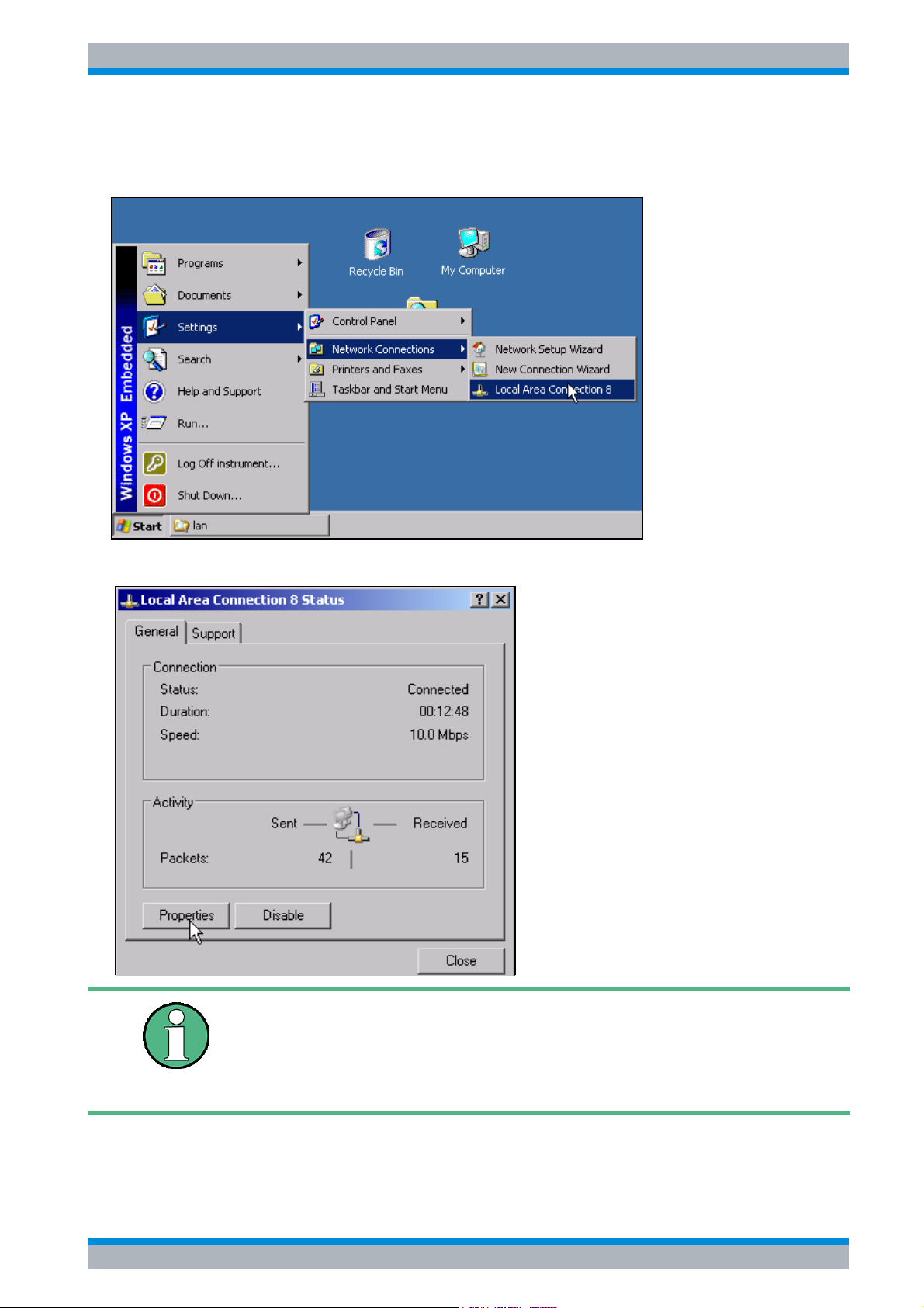
R&S ESPI Preparing for Use
Configuring the LAN Interface (Option R&S FSP-B16 only)
➢ Open the Windows XP Start menu by pressing the Windows key or CTRL+ESC.
➢ Click Settings - Network Connections - Local Area Connection.
The Local Area Connection Status dialog box will open.
Windows XP automatically appends numbers to the name Local Area
Connection Status (e.g. Local Area Connection Status 8) if the
configuration is set up using the New Connection wizard. These
numbers are not important in the following configuration steps and are
therefore omitted.
Quick Start Guide 1164.6613.62 - 02 2.31
Page 62
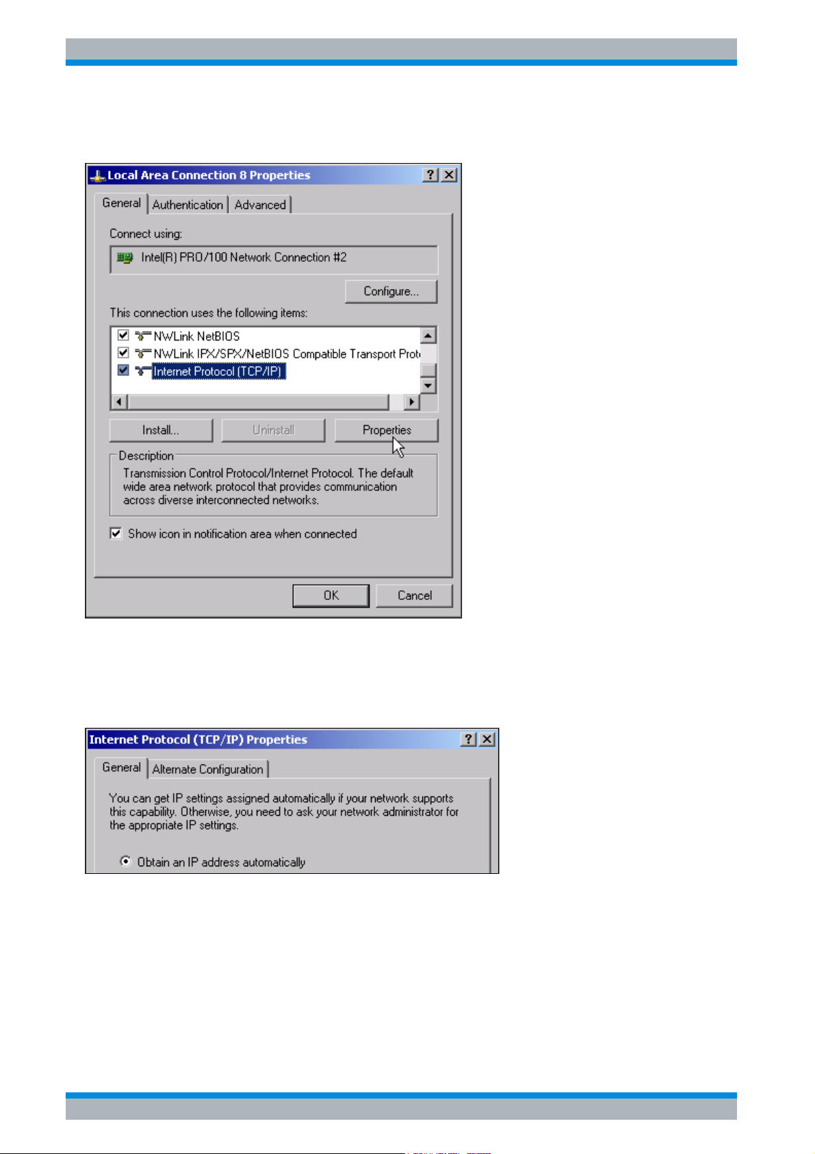
R&S ESPI Preparing for Use
Configuring the LAN Interface (Option R&S FSP-B16 only)
➢ Click the Properties button.
The window with the available network protocols opens.
➢ Click the network protocol you want (TCP/IP in the example).
➢ Click the Properties button.
The dialog box with the settings for the selected network protocol will open. By default,
Obtain an IP address automatically is selected.
➢ Select Use the following IP address to enter a predefined IP address.
2.32 Quick Start Guide 1164.6613.62 - 02
Page 63
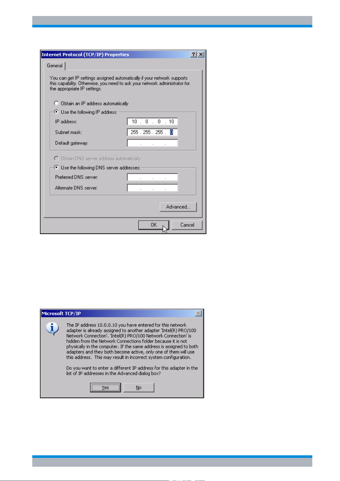
R&S ESPI Preparing for Use
Configuring the LAN Interface (Option R&S FSP-B16 only)
➢ Select IP address and enter the IP address.
➢ Select Subnet mask and enter the required mask.
➢ Click OK.
Windows XP will check the entered settings for correctness and then store the
configuration.
If you have entered an invalid IP address or subnet mask, an error message will appear that
also asks you whether you want to enter a different address or mask:
➢ Click Yes.
The dialog box for entering the TCP/IP parameters will open again.
If all settings are correct, you will be prompted to restart the instrument if required by the
changes.
Quick Start Guide 1164.6613.62 - 02 2.33
Page 64
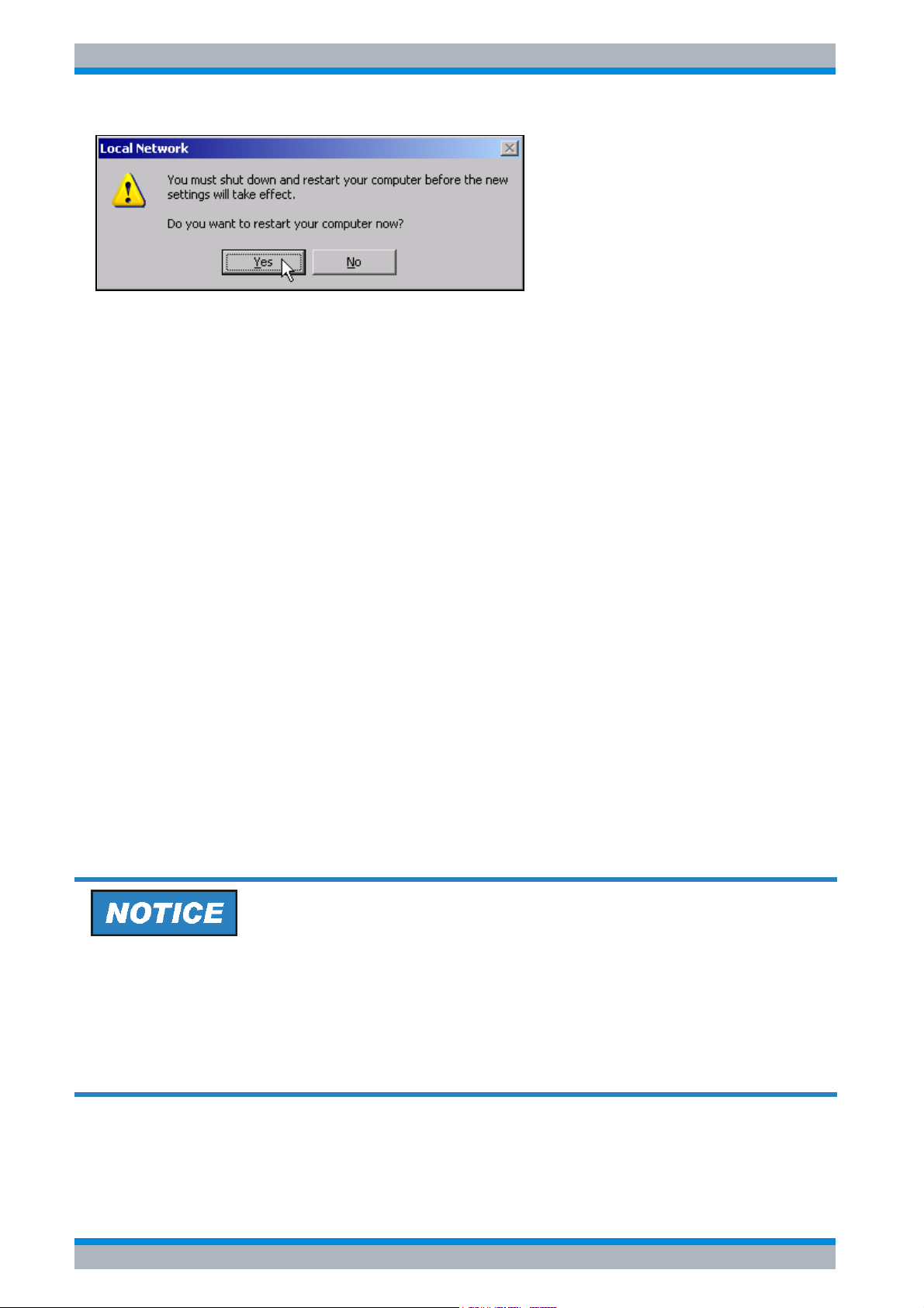
R&S ESPI Preparing for Use
Operating System Properties
➢ Click Yes.
Windows XP will restart the system.
2.5.2.4 Installing Additional Network Protocols and Services
The procedure for installing additional network protocols and services is provided in the
chapter “ Installing Additional Network Protocols & Services” on page 6.3.
2.5.3 Login
Windows XP requires that users identify themselves by entering a user name and password
in a login window. The instrument provides a factory-installed auto login function, i.e. login is
carried out automatically in the background. The ID used for auto login has administrator
rights. As user name and password instrument (lowercase) are set.
For information on how to deactivate the automatic login, refer to chapter “LAN Interface”,
section “ Deactivating the Automatic Login Mechanism” on page 6.14.
2.6 Operating System Properties
2.6.1 Properties Specific to Windows XP
The instrument contains the Windows XP operating system. To ensure that the instrument
software functions properly, certain rules must be adhered to when using the operating
system.
The drivers and programs used under Windows XP have been adapted to the instrument.
To avoid impairments to instrument function, use only the settings described in the
Operating Manual and this manual.
Only update software approved by Rohde & Schwarz may be used to modify existing
instrument software. Likewise, only programs approved by Rohde & Schwarz for use on the
instrument may be run on the instrument.
2.34 Quick Start Guide 1164.6613.62 - 02
Page 65
R&S ESPI Preparing for Use
Operating System Properties
Login
For details refer to section “ Login” on page 2.34.
Administrator ID
The ID used by the instrument to perform auto login has administrator rights.
2.6.1.1 Windows XP Service Packs
The Windows XP operating system on the instrument is supplied with pre-installed XP service
packs (SP2 and additional updates/fixes) that are necessary and suitable for operating the
instrument.
Possible impairment of the instrument functioning
The instrument is equipped with the Windows XP operating system. It is thus possible to
install commercial off-the-shelf software on the instrument. The use and installation of
commercial software may impair the instrument functions. We recommend that you only
execute programs tested by Rohde & Schwarz with regard to their compatibility to the
instrument software. The program packages that have been tested are listed in section
“ Windows XP Software Approved for the Instrument”.
Install only service packs approved by Rohde & Schwarz to avoid impairment of instrument
functions that could lead to the necessity to repair the instrument.
The drivers and programs used on the instrument under Windows XP have been adapted
to the instrument. Existing instrument software must only be modified with update software
released by Rohde & Schwarz.
2.6.1.2 Opening the Windows XP Start Menu
You can open the Windows XP Start menu by pressing the Windows key ( ) or the key
combination CTRL+ESC. From the start menu, you can navigate to the submenus by using
the mouse or the arrow keys. To return to the measurement screen, activate the R&S Analyzer
Interface button in the task bar.
You can also open the Windows Start menu with the OPEN START MENU softkey in the
SETUP menu.
2.6.1.3 Windows XP Software Approved for the Instrument
The driver software that is used and the system settings of Windows XP have been fine-tuned
to support the measurement functions of the R&S ESPI. Thus, flawless instrument function is
ensured only if software and hardware approved or offered by Rohde & Schwarz are used.
Using other software or hardware may cause the functions of the R&S ESPI to perform
improperly or fail.
Quick Start Guide 1164.6613.62 - 02 2.35
Page 66

R&S ESPI Preparing for Use
Operating System Properties
The following program packages have been successfully tested for compatibility with the
measurement instrument software:
• R&S FS-K3 – Software for measuring noise factor and gain
• R&S FS-K4 – Software for measuring phase noise
• R&S Power Viewer (virtual power meter for displaying results of the power sensors of the
R&S NRP-Zxx series)
• Windows XP Remote Desktop
• FileShredder – For reliable deletion of files on the hard disk
• Symantec Norton AntiVirus – Virus-protection software
• McAfee Virusscan
2.36 Quick Start Guide 1164.6613.62 - 02
Page 67

R&S ESPI Firmware Update and Installation of Firmware Options
3 Firmware Update and Installation of
Firmware Options
3.1 Firmware Update . . . . . . . . . . . . . . . . . . . . . . . . . . . . . . . . . . 3.2
3.2 Activating Firmware Options . . . . . . . . . . . . . . . . . . . . . . . . 3.3
Quick Start Guide 1164.6613.62 - 02 3.1
Page 68

R&S ESPI Firmware Update and Installation of Firmware Options
Firmware Update
3.1 Firmware Update
For the latest firmware version refer to the Rohde & Schwarz internet site and download the
most up-to-date firmware.
A detailed description about performing the firmware update in the intrument is given in the
release note, provided on this CD. The release note is also downloadable from the
Rohde & Schwarz internet site.
You can install a new firmware version by using the built-in disk drive, a memory stick, a USB
CD-ROM, or LAN. The firmware update kit contains several disks whose contents must be
stored in separate directories (Disk1 to Disk<n>) when a memory stick or LAN is used. Start
the installation program from the SETUP menu.
➢ Press the SETUP key.
The SETUP menu will open.
➢ Press the NEXT key.
The side menu will open.
➢ Press the FIRMWARE UPDATE softkey.
The subdirectory for installing or uninstalling new firmware versions will open.
➢ Press the UPDATE PATH softkey (only in the case of firmware updates via a memory stick,
CD-ROM or LAN). The entry field for the path with the set of update disks will open.
➢ Enter the drive name and directory and confirm with ENTER.
Example:
The firmware update files are stored on a memory stick in the Update directory. They are
allocated in the Disk1 to Disk<n> subdirectories. After you insert the memory stick, it will be
detected as drive E:.
In this case, the required path specification is E:\UPDATE.
➢ To start the installation program, press the FIRMWARE UPDATE softkey in the submenu.
➢ Confirm the query DO YOU REALLY WANT TO UPDATE THE FIRMWARE? with OK.
The installation program will then guide you through the remainder of the update procedure.
The instrument will perform several automatic shutdowns, until the new base system
firmware is installed properly.
Do not switch the instrument off until the update process has been finished completely.
IEC bus command: "SYST:FIRM:UPD 'E:\UPDATE'"
➢ To restore the previous firmware version, press the RESTORE FIRMWARE softkey.
IEC bus command: --
3.2 Quick Start Guide 1164.6613.62 - 02
Page 69

R&S ESPI Firmware Update and Installation of Firmware Options
Activating Firmware Options
3.2 Activating Firmware Options
Firmware options are enabled by entering license keys via the following operating sequence:
➢ Press the SETUP key.
The SETUP menu will open.
➢ Press the GENERAL SETUP softkey.
➢ Press the OPTIONS softkey.
The OPTIONS menu will open. Options already available are listed in a table that is
displayed when the submenu is opened.
➢ Press the INSTALL OPTION softkey.
The field for entering the license key for the firmware option now appears.
After you enter a valid license key, OPTION KEY OK will appear in the message line and
the option will be entered in the FIRMWARE OPTIONS table.
If you enter an invalid license key, the message OPTION KEY INVALID will appear in the
message line.
➢ The REMOVE OPTION softkey deletes all existing firmware options. To prevent
unintentional deletion, the system asks you to confirm that you really want to perform this
operation.
Quick Start Guide 1164.6613.62 - 02 3.3
Page 70

R&S ESPI Firmware Update and Installation of Firmware Options
Activating Firmware Options
3.4 Quick Start Guide 1164.6613.62 - 02
Page 71

R&S ESPI Basic Operation
4 Basic Operation
4.1 Diagram Layout . . . . . . . . . . . . . . . . . . . . . . . . . . . . . . . . . . . 4.2
4.1.1 Displays in the Diagram Area . . . . . . . . . . . . . . . . . . . . . 4.3
4.2 Setting Parameters . . . . . . . . . . . . . . . . . . . . . . . . . . . . . . . . 4.7
4.2.1 The Keypad . . . . . . . . . . . . . . . . . . . . . . . . . . . . . . . . . . . 4.7
4.2.2 The Rotary Knob and Arrow Keys . . . . . . . . . . . . . . . . . . 4.8
4.2.3 Editing Numeric Parameters . . . . . . . . . . . . . . . . . . . . . . 4.8
4.2.4 Editing Alphanumeric Parameters . . . . . . . . . . . . . . . . . . 4.9
4.2.4.1 Alphanumeric Editor Type 1: . . . . . . . . . . . . . . . . . . . 4.9
4.2.4.2 Alphanumeric Editor Type 2: . . . . . . . . . . . . . . . . . . 4.10
Quick Start Guide 1164.6613.62 - 02 4.1
Page 72
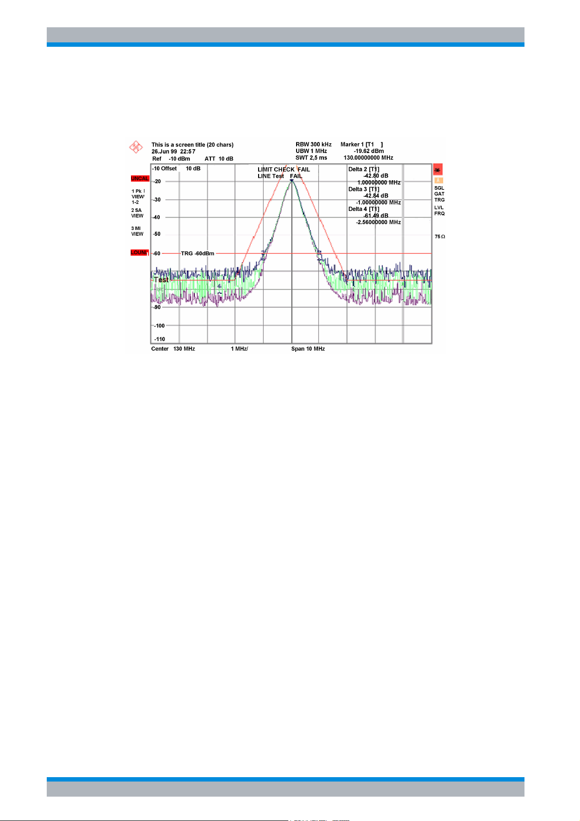
R&S ESPI Basic Operation
Diagram Layout
4.1 Diagram Layout
Status
information
Trace information
Level axis labelling
Logo
title/date
Hardware
settings
Marker/Delta
Marker/Delta
marker
marker
Frequency axis labelling
Fig. 4-1 Screen layout of the R&S ESPI during analyzer operation
Dirty flag
Enhancement
labels
4.2 Quick Start Guide 1164.6613.62 - 02
Page 73

R&S ESPI Basic Operation
Diagram Layout
4.1.1 Displays in the Diagram Area
Hardware settings
Ref Display of the reference level.
Offset Display of the reference level offset.
Att Display of the RF attenuation that has been set.
RBW Display of the resolution bandwidth that has been set.
If the bandwidth does not correspond to the value for automatic coupling, a green
asterisk "*" will appear in front of the field.
MT Indication of the measurement time
PREAMP Indication of the preamplifier status
VBW Display of the video bandwidth that has been set.
If the bandwidth does not correspond to the value for automatic coupling, a green
asterisk "*" will appear in front of the field.
SWT Display of the sweep time that has been set (SWEEP TIME).
If the sweep time does not correspond to the value for automatic coupling, an
asterisk "*" will appear in front of the field. The color of the asterisk will turn to red if
the sweep time is set below the value for automatic coupling. In this case, the sweep
time must be increased.
Marker /
Delta
LIMIT
CHECK
Contains the x and y axis positions of the last marker or delta marker that was set
as well as its index. The value in the square brackets after the index indicates the
trace to which the marker is assigned as well as the active measurement function.
The measurement functions of the markers are indicated with the following
abbreviations:
• FXD Reference fixed marker active
• PHN Phase noise measurement active
• CNT Frequency counter active
• TRK Signal track active
• NOI Noise measurement active
• MOD Measurement of the AM modulation depth active
• TOI measurement active
Display of the results of the limit check.
Quick Start Guide 1164.6613.62 - 02 4.3
Page 74

R&S ESPI Basic Operation
Diagram Layout
Status displays
The status displays on the left side of the diagram indicate any irregularities (e.g. UNCAL).
UNCAL Indicates that one of the following conditions is present:
• Correction data has been switched off (CAL menu, CAL CORR OFF).
– Switch on the correction CAL CORR ON or PRESET.
• No valid correction values are available. This occurs, for example, if a firmware
update is performed followed by a cold start of the instrument.
– Record the correction data (CAL menu, CAL TOTAL).
OVLD Indicates an overload of the input mixer.
– Increase the RF attenuation.
IFOVL Indicates an overload of the IF signal path after the input mixer.
– Increase the reference level.
LOUNL Indicates that an error was detected in the instrument's frequency processing
hardware.
EXREF Is displayed if the instrument was set to an external reference but no signal was
detected on the reference input.
OVEN Indicates that the OCXO reference frequency (option R&S FSP-B4) has not yet
reached its operating temperature. The message usually disappears a few minutes
after power-on.
OVTRC Indicates a temporary overload condition of the input mixer or IF signal path while
the trace is measured with Max Hold, Min Hold or Average (Overload Trace). OVLD
and IFOVL override this indication.
4.4 Quick Start Guide 1164.6613.62 - 02
Page 75

R&S ESPI Basic Operation
Diagram Layout
Trace information
Trace #
Trace number
Trace
number
Detector
auto /
manual
1 PK *
CLRWR
1-3
Detector
Selected detector:
• AP: AUTOPEAK detector
• PK: MAX PEAK detector
• MI: MIN PEAK detector
Trace
mathematics
Trace mode
• SA: SAMPLE detector
• AV: AVERAGE detector
• RM: RMS detector
• QP: QUASIPEAK detector
auto / manual
The selected detector does not match the one for automatic
coupling.
Trace Mode
Display of the sweep mode:
• CLRWR: CLEAR/WRITE
• MAXH: MAX HOLD
• MINH: MIN HOLD
• AVG: AVERAGE
• VIEW: VIEW
Trace Mathematics
Indicates that the trace difference function is activated, e.g. 1-3
in the example means that trace 3 is subtracted from trace 1.
Quick Start Guide 1164.6613.62 - 02 4.5
Page 76

R&S ESPI Basic Operation
Diagram Layout
Enhancement labels:
The enhancement labels on the right-hand side of the measurement diagram indicate that the
user chose instrument settings that affect the measurement results even though this is not
immediately apparent from the display of the measured values.
* (star) The current instrument setting does not match the one during which the displayed
traces were recorded. This occurs in the following cases:
– The instrument setting is changed while a measurement is in progress.
– The instrument setting is changed in the SINGLE SWEEP mode after the end
of the sweep, and a new sweep is not started.
– The instrument setting is changed after a trace has been set to VIEW.
The display remains on screen until the user eliminates the cause. In some
cases, this involves starting a new sweep (SINGLE SWEEP mode) or switching
the affected trace to BLANK.
A/B Designation for screen A/B. If screen A/B is activated for entering measurement
parameters, the label background will be in color.
SGL The sweep is set to SINGLE SWEEP.
GAT The frequency sweep is controlled via the EXT TRIG/GATE connector.
TRG Instrument triggering is not free running (≠ FREE RUN).
LVL A level offset ≠ 0 dB is set.
FRQ A frequency offset ≠ 0 Hz is set.
TDF A TRANSDUCER FACTOR is activated.
TDS A TRANSDUCER SET is activated.
PRN Printer output is active.
75 Ω The input impedance of the instrument is set to 75 Ω.
EXT The instrument is configured for operation with an external reference.
PA The RF PREAMPLIFIER is switched on (option R&S ESPI-B2).
PS The PRESELECTOR is switched on.
3DB Gauss Filter (3 dB)
6DB EMI Filter (6 dB)
FFT FFT Filter
CHN Channel Filter
RRC RRC Filter
4.6 Quick Start Guide 1164.6613.62 - 02
Page 77
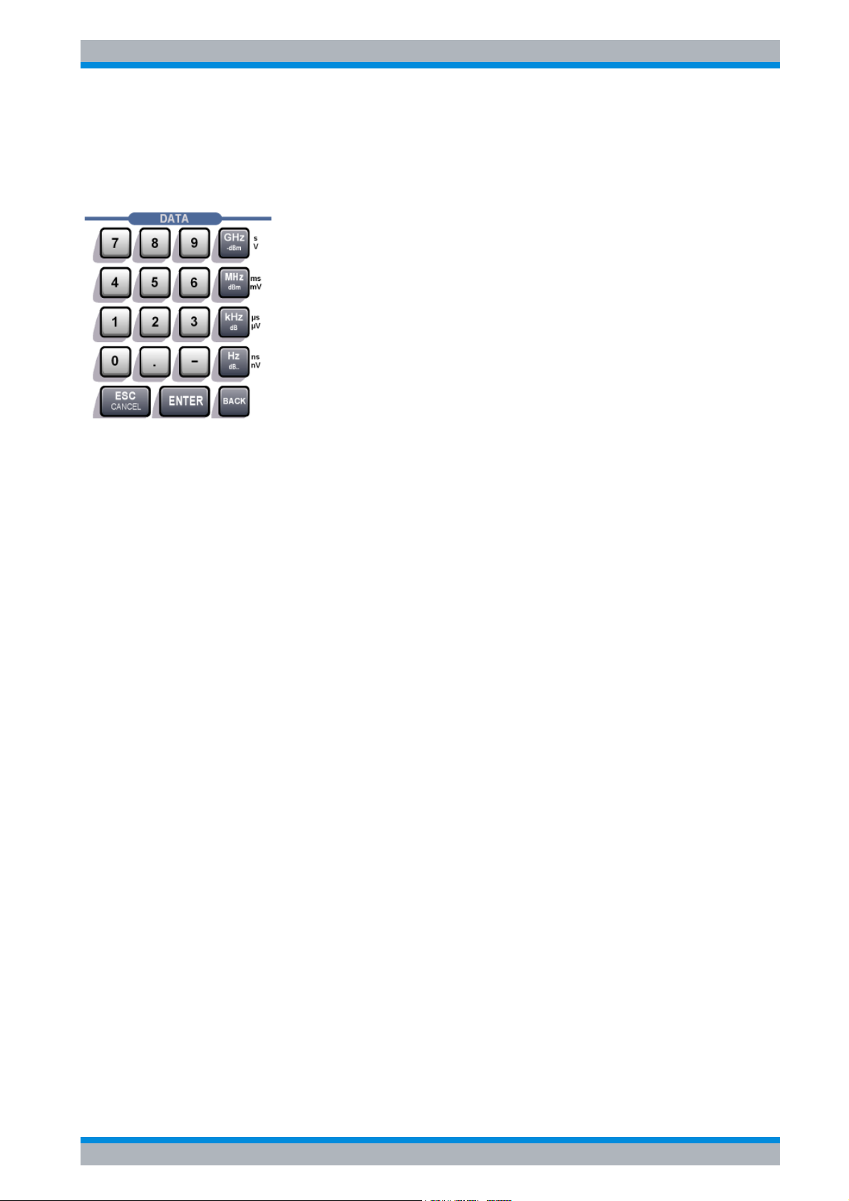
R&S ESPI Basic Operation
Setting Parameters
4.2 Setting Parameters
4.2.1 The Keypad
The keypad is used to enter numeric parameters. It contains the following keys:
• Numeric keys 0...9
• Decimal point
Inserts a decimal point "." at the cursor position.
• Sign key
Changes the sign of a numeric parameter.
In the case of an alphanumeric parameter, inserts a "-" at the cursor position.
• Unit keys (GHz/-dBm MHz/dBm, kHz/dB and Hz/dB)
These keys add the selected unit to the entered numeric value and complete the entry.
In the case of level entries (e.g. in dB) or dimensionless values, all units have the value "1"
as multiplying factor. Thus, they have the same function as an ENTER key. The same is
true for an alphanumeric entry.
In addition, the unit keys open and close selection fields in tables (subtables).
• BACK key
– If a numeric entry has already been started, this key deletes the character to the left of
the cursor.
– If an entry has been completed or not yet started, this key toggles between the currently
and previously valid value (UNDO function).
• ESC/CANCEL key
– Closes the entry field if an entry has been started or has not yet been made. The original
value is retained.
– Closes the entry field if an entry has been completed.
– Closes the System Messages dialog box.
• ENTER key
– Concludes dimensionless entries. The new value is accepted.
Quick Start Guide 1164.6613.62 - 02 4.7
Page 78
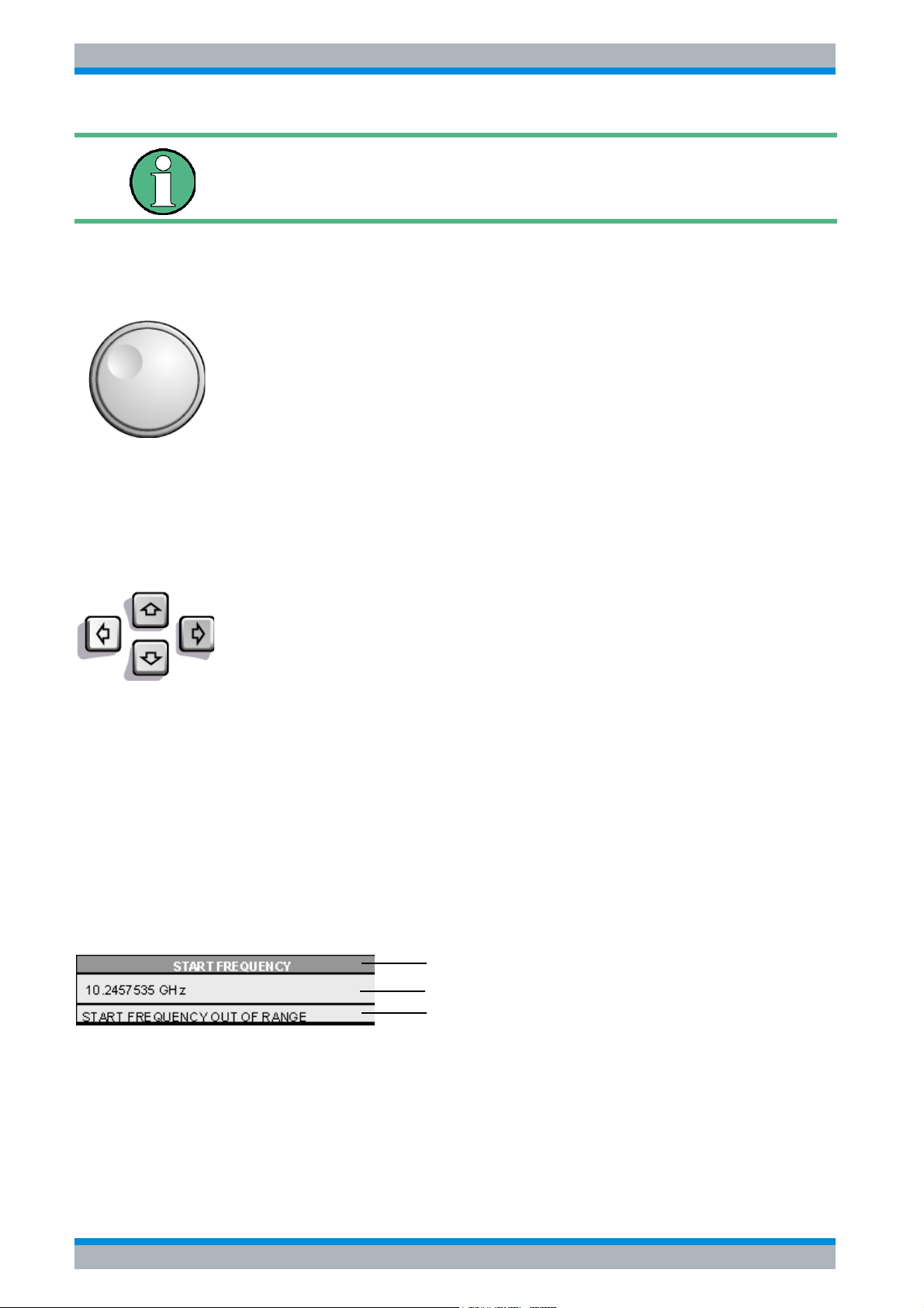
R&S ESPI Basic Operation
Setting Parameters
With frequency entries, the ENTER key corresponds to the Hz key.
With time data, it corresponds to the µs (kHz) key.
4.2.2 The Rotary Knob and Arrow Keys
The rotary knob and arrow keys are located next to the keypad.
The rotary knob has several functions:
• Increments (clockwise direction) or decrements (counterclockwise
direction) the instrument parameter at a defined step width in the case
of a numeric entry.
• Shifts the selection bar horizontally or vertically within tables as long as
an entry field is not open. The arrow keys are used to change the
direction of motion (horizontal/vertical).
• Selects the individual letters when the alphanumeric editor is used.
• Shifts markers, limit lines, etc. on the screen.
• When it is pressed, it concludes an entry.
Within a table, the arrow keys move the selection bar to the desired
position.
Within the alphanumeric editor, the Ul or Ur arrow keys move the cursor
to the desired position.
The Uu or Ud arrow keys do the following:
• Increase or decrease the instrument parameter in the case of numeric
entries.
• Switch between the editing line and the character selection in the case
of alphanumeric entries.
4.2.3 Editing Numeric Parameters
Numeric values are always entered in a data entry field that automatically appears after the
parameter is selected.
Title line with parameter designation
Editing line with parameter value and unit
Status and error messages
The title line shows the name of the instrument parameter that was selected. The entry is
performed in the editing line. After the entry field is opened, it will contain the currently valid
parameter value and its unit. The optional third and fourth lines show status and error
messages which always refer to the current entry.
4.8 Quick Start Guide 1164.6613.62 - 02
Page 79
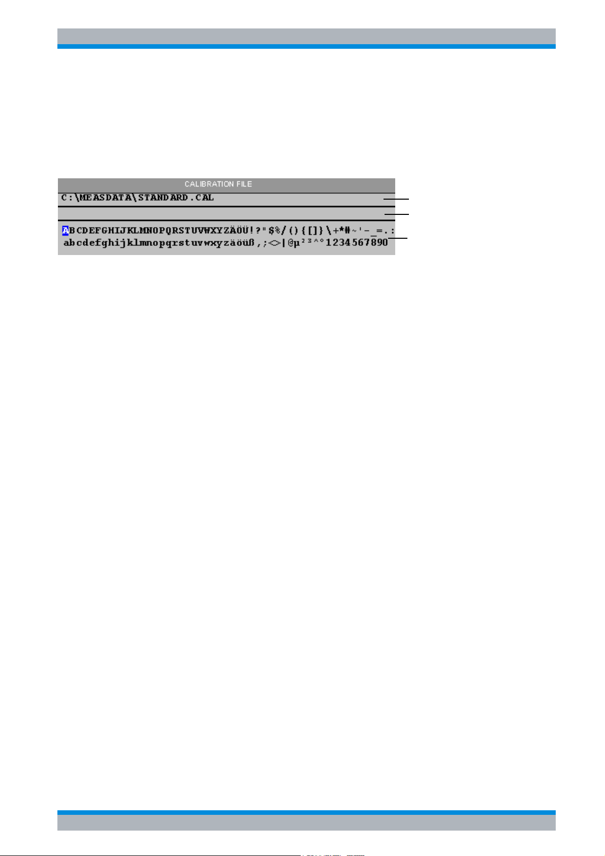
R&S ESPI Basic Operation
Setting Parameters
4.2.4 Editing Alphanumeric Parameters
If an external keyboard is not available, the character selection field is automatically opened
for entering alphanumeric parameters. Two models of the alphanumeric editor are available.
4.2.4.1 Alphanumeric Editor Type 1:
Entry (editing) line
Message line
Character selection line
The Uu or Ud arrow keys switch between the editing line and the character selection field.
Entering the text
➢ Select the parameter.
Data entry is automatically activated after the data entry field is opened. The cursor is now
located at the start of the previous entry in the editing line.
➢ Using the Ud arrow key, place the cursor in the character selection field.
The cursor now marks the first letter of the editor.
➢ Using the Ul and Ur arrow keys or the rotary knob, place the cursor on the character that
you want to enter in the editing line.
➢ Press either the ENTER key or the rotary knob.
The character will be added to the editing line.
Correcting the entry
➢ Using the Uu arrow key, place the cursor in the editing line.
➢ Using the Ul and Ur arrow keys or the rotary knob, place the cursor after the character you
want to delete.
➢ Press the BACK key.
The entry to the left of the cursor will be deleted.
Correcting the entry
➢ Using the Uu key, place the cursor in the editing line.
➢ Press one of the unit keys or the rotary knob.
The data entry field will close, and the new entry will be accepted by the instrument.
Cancelling the entry
➢ Press the ESC key.
The data entry field will close, and the previous entry will be retained.
Quick Start Guide 1164.6613.62 - 02 4.9
Page 80
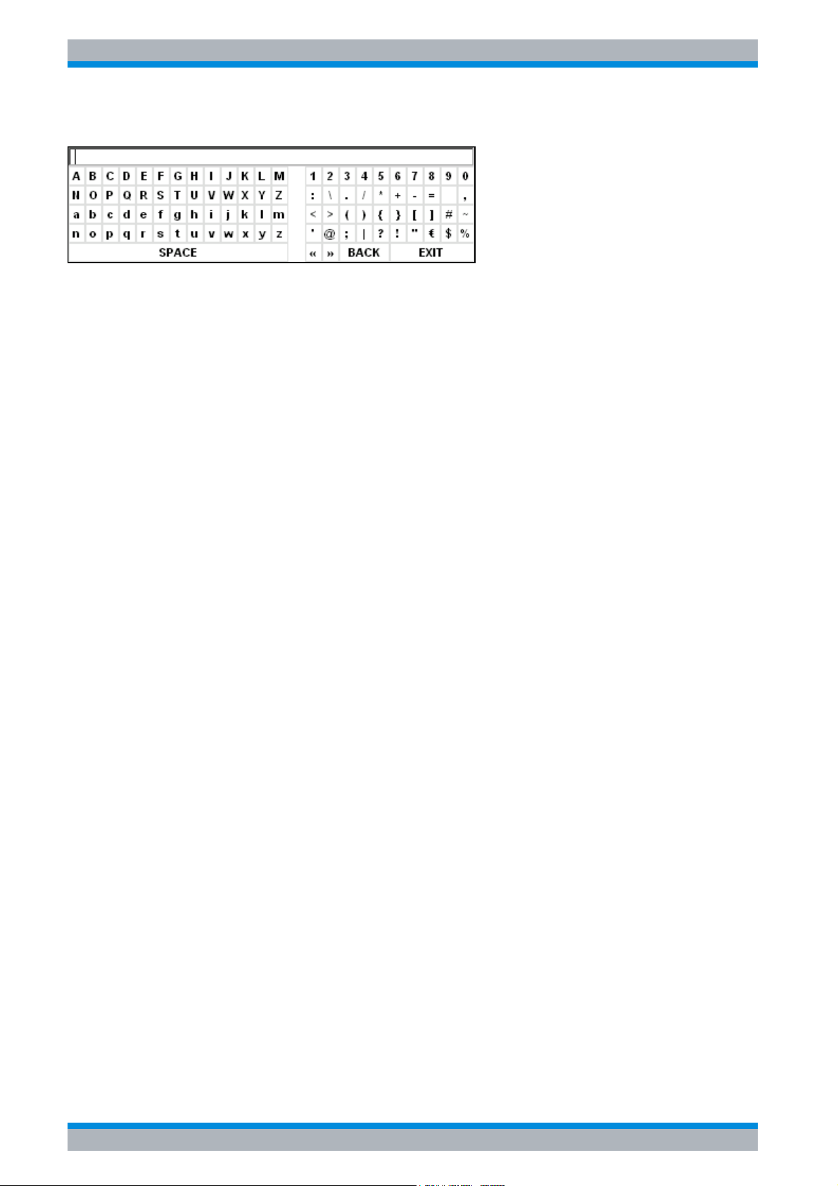
R&S ESPI Basic Operation
Setting Parameters
4.2.4.2 Alphanumeric Editor Type 2:
The entry area consists of two parts:
• The editing line
• The character selection field
The Uu or arrow keys switch between the editing line and the character selection field.
Entering the text
➢ Select a parameter.
Data entry is automatically activated after the data entry field is opened. In tables, the
character selection field is accessed by using the Ud arrow key.
The cursor is now located at the start of the existing entry in the editing line.
➢ Using the Ud arrow key, place the cursor in the character selection field.
The cursor now marks the first character of the editor.
➢ Using the Ul and Ur arrow keys or the rotary knob, place the cursor on the character that
you want to enter in the editing line.
➢ Press the ENTER key or the rotary knob.
The character will be added to the editing line.
Correcting the entry (alternative 1)
➢ Using the rotary knob, go to the << character in the character selection field.
➢ By pressing the rotary knob on << and >>, place the cursor after the character you want to
delete.
➢ Using the rotary knob, select the BACK field and press the rotary knob.
The entry to the left of the cursor in the editing line will be deleted.
Correcting the entry (alternative 2)
➢ Using the Uu arrow key, place the cursor in the editing line.
➢ Using the Ul and Ur arrow keys or the rotary knob, place the cursor after the character you
want to delete.
➢ Press the BACK key.
The entry to the left of the cursor will be deleted.
4.10 Quick Start Guide 1164.6613.62 - 02
Page 81

R&S ESPI Basic Operation
Setting Parameters
Completing the entry (alternative 1)
➢ Using the rotary knob, select the EXIT field and then press the rotary knob.
The data entry field will close, and the new entry will be accepted by the instrument.
Completing the entry (alternative 2)
➢ Using the Uu arrow key, place the cursor by the editing line.
➢ Press one of the unit keys or the rotary knob.
The data entry field will close, and the new entry will be accepted by the instrument.
Cancelling the entry
➢ Press the ESC key.
The data entry field will close, and the previous entry will be retained.
Quick Start Guide 1164.6613.62 - 02 4.11
Page 82

R&S ESPI Basic Operation
Setting Parameters
4.12 Quick Start Guide 1164.6613.62 - 02
Page 83

R&S ESPI Basic Measurement Examples
5 Basic Measurement Examples
5.1 Introduction . . . . . . . . . . . . . . . . . . . . . . . . . . . . . . . . . . . . . 5.2
5.2 Performing a Level and Frequency Measurement . . . . . . . 5.3
Quick Start Guide 1164.6613.62 - 02 5.1
Page 84
R&S ESPI Basic Measurement Examples
Introduction
5.1 Introduction
This section describes a typical and simple measurement task for an EMI test receiver. Each
operating step is explained with the aid of R&S ESPI for rapid familiarization of the user
without the need to know all the details of the operating functions.
In the introductory example a standard measurement of level and frequency is performed with
the aid of the SCAN TABLE. This measurement is an overview and pre-certification
measurement to be performed before the final standard-conformal measurement is carried
out. Each operating step is explained with the aid of R&S ESPI for rapid familiarization of the
user without the need to know all the details of the operating functions.
If unknown (RFI) signals are to be measured, it is strongly
recommended to provide for at least 10 dB RF attenuation at the RF
input in order to protect the input circuit.
In the following example, the R&S ESPI is set to default values in the receiver mode. The
default setup is activated by pressing first the RECEIVER hotkey and then the PRESET key.
The main default parameters in receiver mode are listed in the following table:
Parameter Setting
Receiver frequency 100 MHz
RF attenuation Auto
Preamplifier Off
Detector AV
Measurement time 100 ms
RES bandwidth 120 kHz
Demodulator Off
Trigger Free run
5.2 Quick Start Guide 1164.6613.62 - 02
Page 85

R&S ESPI Basic Measurement Examples
Performing a Level and Frequency Measurement
5.2 Performing a Level and Frequency Measurement
Measurement
Measurement and display of RFI signal levels versus frequency is one of the most frequent
tasks performed by an EMI Test Receiver. In the case of unknown signals, PRESET values
will mostly be used for the measurement. If levels higher than +137 dBµV (10 dB
RF attenuation) are expected or possible, a power attenuator has to be connected in front of
the EMI Test Receiver input. Very high levels may otherwise damage or destroy the attenuator
or input mixer.
Main Test Receiver Functions
The main functions required for the level and frequency measurement are setting the SCAN
TABLE (START FREQUENCY, STOP FREQUENCY, STEPSIZE), selecting the resolution
(IF) bandwidth (RES BW), setting the measurement time (MEAS TIME) and selecting the
detectors (e.g. peak or average) and MARKER functions required for the analysis.
Measurement Sequence - Level and Frequency Measurement
In this example, the spectrum of the signal present at RF INPUT is recorded in the frequency
range 150 kHz to 30 MHz. The SCAN TABLE and associated parameters are manually set.
The example is generally suitable for all fast pre-compliance measurements required for
measuring unknown noise spectra of DUTs in the development stage and for modifying
prototypes and can be used as a basis for final tests later on.
The high speed of fully synthesized scans, the frequency and amplitude accuracy and the
wide dynamic range of the R&S ESPI EMI Test Receiver are of utmost importance and very
useful for these measurements.
Short form
1. Reset the instrument.
2. Select the receiver mode.
3. Program a SCAN TABLE.
4. Select the detectors.
5. Apply the signal.
6. Start the scan.
7. Analyze the level in frequency domain.
– Analyze the level in frequency domain using the marker functions.
– Analyze the level in frequency domain using the peak search functions.
8. Set the SPLIT SCREEN function.
9. Tune the receiver frequency and obtain final test results using the QUASIPEAK detector.
10.From overview to standard-conformal measurement
Quick Start Guide 1164.6613.62 - 02 5.3
Page 86
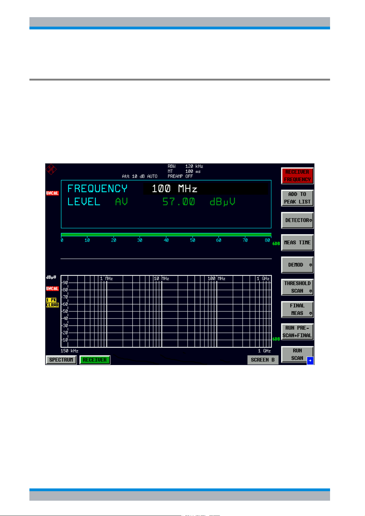
R&S ESPI Basic Measurement Examples
Performing a Level and Frequency Measurement
11.Store the test results, tables or diagrams.
Detailed procedure
1. Reset the instrument.
➢ Press the PRESET key.
2. Select the receiver mode.
➢ Press the RECEIVER hotkey.
The receiver mode is set. The main receiver menu is displayed:
Fig. 5-1 Display after selecting the default setup in receiver mode
5.4 Quick Start Guide 1164.6613.62 - 02
Page 87
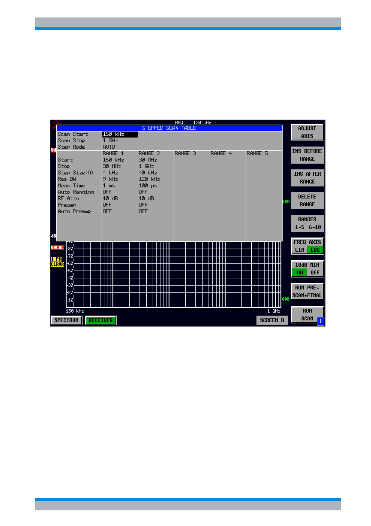
R&S ESPI Basic Measurement Examples
Performing a Level and Frequency Measurement
3. Program a SCAN TABLE.
➢ Press the SWEEP key.
➢ Press the USE SCAN TABLE softkey.
A dialog box is displayed where the whole display range can be defined and divided into
scan subranges.
Fig. 5-2 Scan range after selecting default setup with PRESET
After PRESET a scan range of 150 kHz to 1 GHz is set on the frequency axis. The stop
frequency is set to 30 MHz.
➢ Press the Ud arrow key repeatedly until a line is marked in the SCAN TABLE.
➢ Press the Ur arrow key field.
An entry in the RANGE 2 column is marked.
➢ Press the DELETE RANGE softkey.
All entries in the RANGE 2 column are cleared. The following SCAN TABLE is displayed:
Quick Start Guide 1164.6613.62 - 02 5.5
Page 88
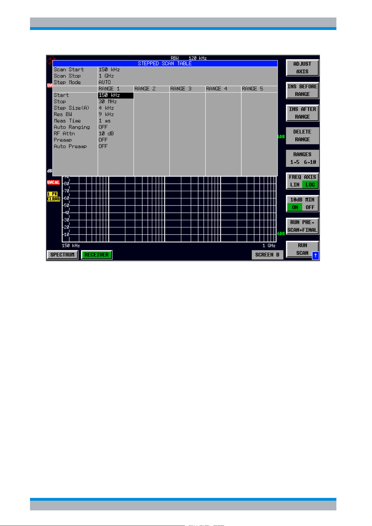
R&S ESPI Basic Measurement Examples
Performing a Level and Frequency Measurement
Fig. 5-3 Modified SCAN TABLE for preparing a scan
After editing the scan subrange, the frequency display has to be adapted to the new
settings. The lowest start frequency of the range 1 scan and the highest stop frequency
of the subsequently defined subranges are used for defining the start and stop
frequencies of the graphics display. In the example, the limit frequencies of SCAN
RANGE 1 are therefore also the limits of the graphics display.
➢ Press the ADJUST AXIS softkey.
The respective frequency values in the table are transferred to adapt the display.
➢ Press the menu change key PREV.
The USE SCAN TABLE submenu is closed.
5.6 Quick Start Guide 1164.6613.62 - 02
Page 89

R&S ESPI Basic Measurement Examples
Performing a Level and Frequency Measurement
4. Select the detectors.
Up to three detectors can be connected in parallel to simultaneously display the amplitude
at every frequency as a function of detector weighting. When a parallel detector is selected,
the slowest detector (in the sense of a calibrated measurement) determines the speed or
the total measurement time required for the scan. The fastest scan is performed when the
peak detector is used as the sole detector.
In the example, the peak detector (trace 1) and the average detector (trace 2; default) are
used in an overview measurement.
➢ Press the TRACE key.
The TRACE menu is displayed.
➢ Press the SELECT TRACE softkey.
A data input field is displayed.
➢ Enter 1 as trace number and confirm with the ENTER key.
➢ Press the DETECTOR softkey.
The DETECTOR menu is displayed.
➢ Press the MAX PEAK softkey to select the detector.
The peak detector is selected for trace 1.
➢ Press the TRACE key again.
➢ Press the SELECT TRACE softkey again.
➢ Enter 2 as trace number and confirm with the ENTER key.
➢ Press the CLEAR / WRITE softkey.
In the DETECTOR menu, select the AVERAGE detector.
5. Apply the signal.
➢ Connect the RF cable to the RF input.
6. Start the scan.
➢ Press the SWEEP key.
The SWEEP/SCAN menu is displayed.
➢ Press the RUN SCAN softkey.
The HOLD SCAN and STOP SCAN softkeys are displayed.
The measurement with the selected PEAK and AVERAGE detectors is continuously
repeated because the default setting CONTINUOUS SCAN remains unchanged.
Quick Start Guide 1164.6613.62 - 02 5.7
Page 90
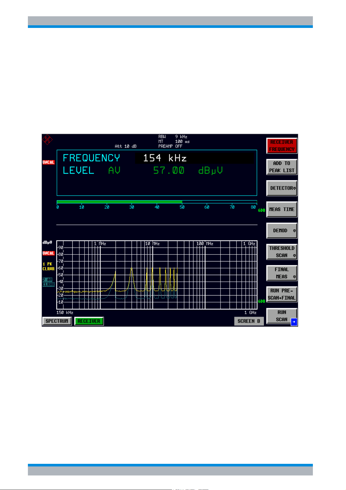
R&S ESPI Basic Measurement Examples
Performing a Level and Frequency Measurement
➢ Press the STOP SCAN softkey.
The measurement is aborted.
Peak and average results (see Fig. 5-4) should be further analyzed with the aid of the
built-in marker functions.
Depending on the DUT, diverse trace forms are obtained. For this reason the diagram
below should be regarded as an example.
The scaling of the y-axis can be adjusted in the AMPT menu by means of softkey GRID
RANGE LOG MANUAL if necessary.
Fig. 5-4 Result display of standard pre-compliance measurement using peak/average
detector
7. Analyze the level in frequency domain using the marker functions.
Alternatively, you can use the peak search functions (see step 8).
➢ Press the MRK key.
The marker jumps to the largest signal peak shown on the display screen.
5.8 Quick Start Guide 1164.6613.62 - 02
Page 91

R&S ESPI Basic Measurement Examples
Performing a Level and Frequency Measurement
When the marker is switched on for the first time, it automatically
performs the PEAK SEARCH function as demonstrated in this
example.
If a marker was already active, the PEAK softkey in the MRK-> menu
must be pressed in order to set the currently active marker to the
displayed signal maximum.
The level and frequency measured by the marker can be read in the marker field at the
upper edge of the display screen.
➢ Move the marker on the trace with the aid of the rotary knob.
The respective level and frequency values are displayed in the marker field.
8. Analyze the level in frequency domain using the peak search functions.
Alternatively, you can use the marker functions (see step 7).
➢ Press the Press the MKR−> key.
The MKR−> menu is displayed.
➢ Press the PEAK softkey.
The marker is positioned at the maximum level in the display.
➢ Press the menu change key NEXT.
➢ Press the NEXT MIN softkey.
The marker moves to the next lower level in the spectrum irrespective of whether the
frequency is higher or lower than that of the previously measured PEAK value.
➢ Press the menu change key PREV.
➢ Press the NEXT PEAK RIGHT softkey.
The marker is displayed on the next peak level at a higher frequency (see Fig. 5-5).
The displayed spectrum can be further analyzed with the aid of up to 4 markers. The
markers can be assigned to different traces.
➢ Press the DISP key.
The DISPLAY menu is displayed.
Quick Start Guide 1164.6613.62 - 02 5.9
Page 92
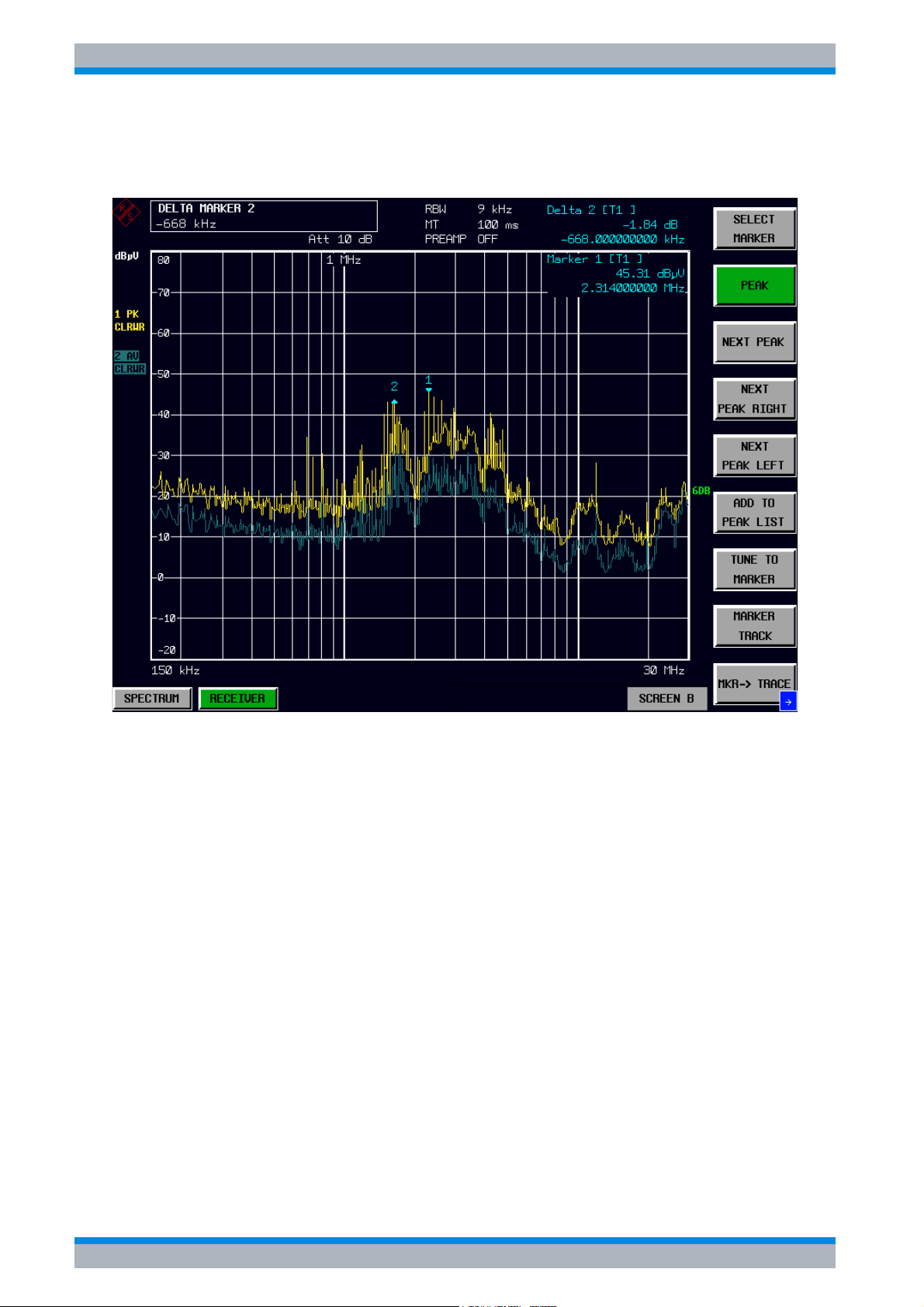
R&S ESPI Basic Measurement Examples
Performing a Level and Frequency Measurement
➢ Press the FULL SCREEN softkey.
One window is displayed on the screen
Fig. 5-5 Screen display with marker
9. Set the SPLIT SCREEN function.
The SPLIT SCREEN function simplifies the analysis of measured data, particularly at
critical frequencies. In the split-screen mode, the frequency, e.g. that of the active marker,
and the level of the active detectors are displayed in the upper half of the screen numerically
and on a bar graph.
➢ Press the DISP key.
The DISPLAY menu is displayed.
➢ Press the SPLIT SCREEN softkey.
Two windows are displayed on the screen.
5.10 Quick Start Guide 1164.6613.62 - 02
Page 93

R&S ESPI Basic Measurement Examples
Performing a Level and Frequency Measurement
10.Tune the receiver frequency and obtain final test results using the QUASIPEAK
detector.
The currently measured frequency can be rapidly changed e.g. with the TUNE TO
MARKER softkey in the MKR−> menu. Other or additional detectors can be switched on at
this receive frequency and an overview of levels of all active detectors is given. For
measurements to standard, the measurement time must first be set to 1 s.
➢ Press the MKR key.
Marker 1 is displayed.
Frequency and level values can be read in the marker field at the top left of the screen.
➢ Press the MKR−> key.
The MKR−> menu is displayed.
➢ Press the TUNE TO MARKER softkey.
The current receive frequency is tuned to the marker frequency.
A measurement time of 1 s must be set for measurements to standard.
➢ Press the RECEIVER hotkey.
The RECEIVER menu is displayed.
➢ Press the MEAS TIME softkey.
The window with the currently set measurement time is displayed (1 ms in the example).
➢ Enter 1 on the numeric keypad and terminate by pressing s.
The new measurement time is displayed.
The quasi peak detector should now be switched on in addition.
➢ Press the DETECTOR softkey.
The DETECTOR menu is displayed. The peak and average detectors of the pre-
compliance measurement are active.
➢ Press the QUASIPEAK and the MAX PEAK softkey.
The level at the current receive frequency is displayed for three detectors numerically
and on three bar graphs (see Fig. 5-6).
Quick Start Guide 1164.6613.62 - 02 5.11
Page 94
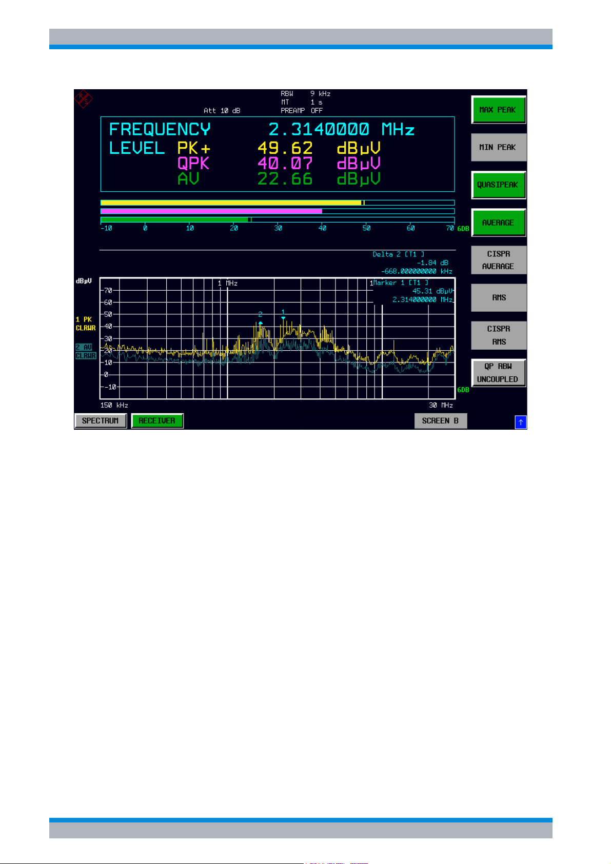
R&S ESPI Basic Measurement Examples
Performing a Level and Frequency Measurement
Fig. 5-6 Analysis of single frequencies with standard measurement time and several
detectors
11.From overview to standard-conformal measurement
➢ Data reduction and automatic routines for final measurement
The R&S ESPI offers several data reduction methods for interactive or automatic final
measurements. For details refer to the Operating Manual, chapter 4.
➢ Limit lines
A final measurement to standard can be performed when active limit lines are displayed
in the diagram during the described analysis and measurements are repeated at all
critical frequencies using the standard measurement time and a corresponding detector.
For details refer to the Operating Manual, chapter 4.
➢ Transducer
Care should be taken that the correction values or transducer factors available in tabular
form are considered in the measurement result when accessories with frequencydependent characteristics are used. Several correction tables can be combined to form
a transducer set. For details refer to the Operating Manual, chapter 4.
5.12 Quick Start Guide 1164.6613.62 - 02
Page 95

R&S ESPI Basic Measurement Examples
Performing a Level and Frequency Measurement
12.Store the test results, tables or diagrams.
In the example, test results are stored on a memory stick. Measured data are output in
WMF format for use in other applications.
DEVICE1 and output in WMF format is automatically selected with PRESET.
➢ Press the HCOPY key.
The HCOPY SETTINGS menu is displayed where the output of measurement and
device data can be configured and started.
➢ Connect a memory stick to the USB port.
➢ Press the PRINT SCREEN softkey.
The output is started. A window to enter file name and path.
➢ Enter file name and path using the built-in auxiliary line editor or the external keyboard,
e.g. F:\ display.wmf and confirm the entry with the ENTER key.
➢ Press the ENTER key.
The screen content is stored on the disk under the specified file name.
During storing the softkeys are blanked. Operation in the menus can be continued when
the softkeys are displayed again.
The file can be used in other Windows applications, i.e. it can be linked.
Fig. 5-7 gives an example of a stored display. In the example, two limit lines are active
and 4 markers positioned in the spectrum.
Quick Start Guide 1164.6613.62 - 02 5.13
Page 96
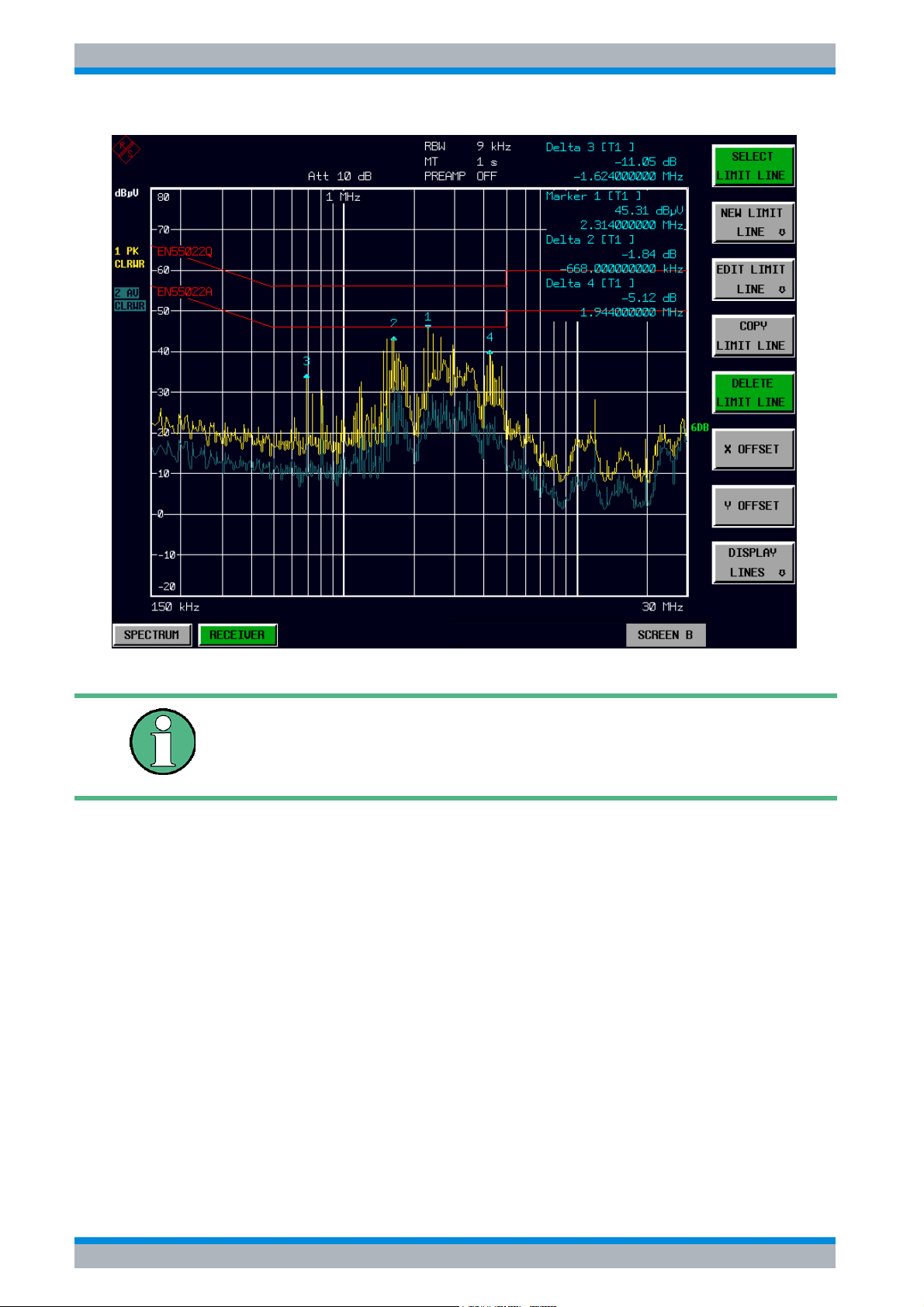
R&S ESPI Basic Measurement Examples
Performing a Level and Frequency Measurement
Fig. 5-7 Result display stored in a file in WMF format
A detailed description of the file management for complete EMI Test
Receiver setups, data records for traces (traces 1-3), limit lines and
transducer is given in the Operating Manual, chapter 4, section
"Operating Concept of File Managers".
5.14 Quick Start Guide 1164.6613.62 - 02
Page 97

R&S ESPI LAN Interface
6 LAN Interface
6.1 Installing Additional Network Protocols & Services . . . . . 6.3
6.2 Configuration Examples . . . . . . . . . . . . . . . . . . . . . . . . . . . . 6.6
6.3 Subsequent Changes to the Network Configuration . . . . . 6.6
6.4 Configuring the Windows XP Firewall . . . . . . . . . . . . . . . . 6.8
6.5 Operating the Instrument without a Network . . . . . . . . . . . 6.9
6.6 Operating the Instrument in a Network . . . . . . . . . . . . . . . . 6.9
6.6.1 Creating Users . . . . . . . . . . . . . . . . . . . . . . . . . . . . . . . . . 6.9
6.6.2 Changing the User Password . . . . . . . . . . . . . . . . . . . . 6.11
6.6.3 NOVELL Network only: Configure NOVELL Client . . . . 6.13
6.6.4 Logging On to the Network . . . . . . . . . . . . . . . . . . . . . . 6.14
6.6.5 Deactivating the Automatic Login Mechanism . . . . . . . . 6.14
6.6.6 Reactivating the Automatic Login Mechanism . . . . . . . . 6.14
6.6.7 Using Network Drives . . . . . . . . . . . . . . . . . . . . . . . . . . 6.15
6.6.8 Installing a Network Printer . . . . . . . . . . . . . . . . . . . . . . 6.17
6.6.9 Sharing Directories (only with Microsoft Networks) . . . . 6.21
6.7 Manual Operation of the R&S ESPI with XP Remote
Desktop . . . . . . . . . . . . . . . . . . . . . . . . . . . . . . . . . . . . . . . . . . . . 6.24
6.7.1 Introduction . . . . . . . . . . . . . . . . . . . . . . . . . . . . . . . . . . 6.24
6.7.2 Configuring the R&S ESPI for Use of XP Remote
Desktop . . . . . . . . . . . . . . . . . . . . . . . . . . . . . . . . . . . . . . . . . . 6.24
6.7.3 Configuring the Controller . . . . . . . . . . . . . . . . . . . . . . . 6.27
Quick Start Guide 1164.6613.62 - 02 6.1
Page 98

R&S ESPI LAN Interface
6.7.4 Connection Setup with the R&S ESPI . . . . . . . . . . . . . . 6.30
6.7.5 Interrupting and Restoring the Remote Desktop
Connection with the R&S ESPI . . . . . . . . . . . . . . . . . . . . . . . . 6.33
6.7.6 Deactivating the R&S ESPI from the Controller . . . . . . . 6.34
In some of the following step-by-step instructions, user names and
passwords must be entered. This requires a mouse and an external
keyboard is (the connection is described in sections “ Connecting a
Mouse” and “ Connecting an External Keyboard” on page 2.8).
6.2 Quick Start Guide 1164.6613.62 - 02
Page 99
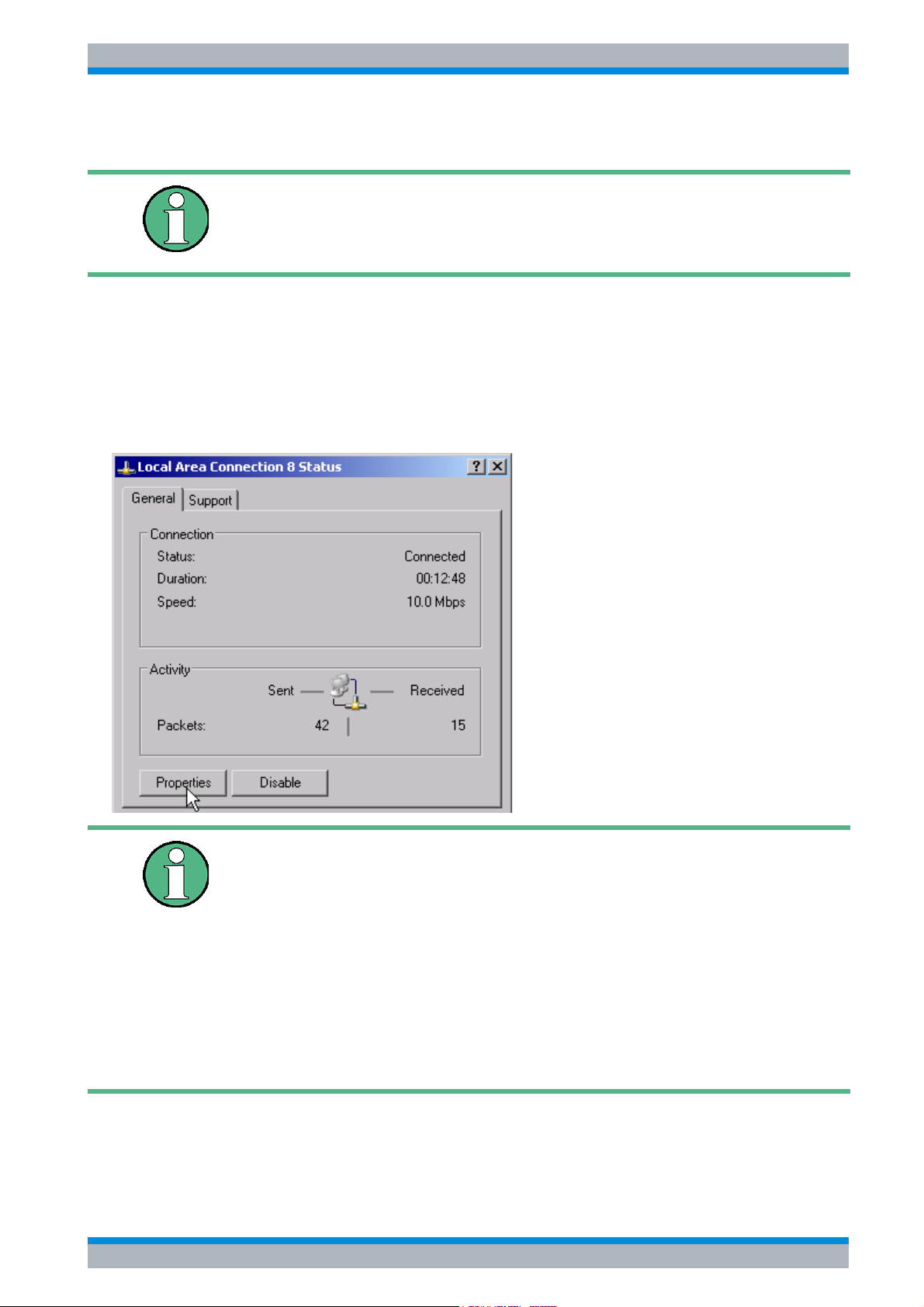
R&S ESPI LAN Interface
Installing Additional Network Protocols & Services
6.1 Installing Additional Network Protocols & Services
Your network administrator knows which protocols are necessary. In
the case of the RSIB protocol and VXI11 support, TCP/IP must always
be installed. In the following example, the support for Novell Network
will also be installed..
➢ Press the SETUP key.
The SETUP menu will open.
➢ Press the GENERAL SETUP softkey.
The GENERAL SETUP menu will open.
➢ Press the CONFIGURE NETWORK softkey.
The Local Area Connection Status dialog box will open.
• Windows XP automatically appends numbers to the name Local
Area Connection Status (e.g. Local Area Connection Status 8) if the
configuration is created using the New Connection wizard. Since
these numbers are unimportant in the following configuration steps,
they are omitted in the description.
• Alternatively it is possible to access the dialog using a connected
external keyboard. Proceed as follows:
Open the Windows XP Start menu with the Windows key or
CTRL+ESC. Select Settings - Network Connections - Local Area
Connection.
The Local Area Connection Status dialog box will open.
➢ Click the Properties button.
The dialog box containing the available network protocols will open.
Quick Start Guide 1164.6613.62 - 02 6.3
Page 100
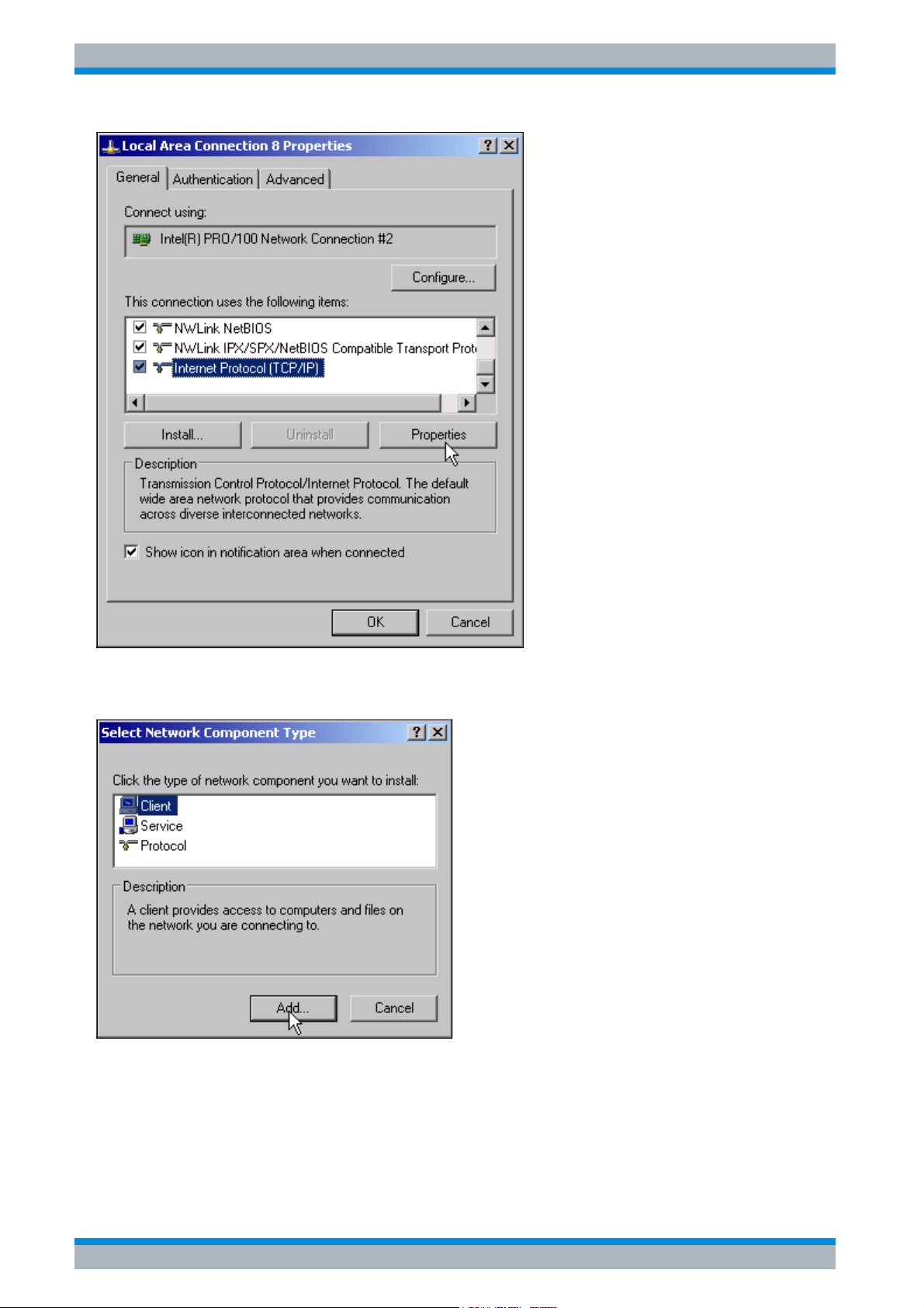
R&S ESPI LAN Interface
Installing Additional Network Protocols & Services
➢ Click the Install button.
The list of available network components will open.
➢ Select Client.
➢ Click the Add... button.
The list of available network protocols will open.
6.4 Quick Start Guide 1164.6613.62 - 02
 Loading...