


Operating Manual
EMI Test Receiver
ESPI3
1142.8007.03
Test and Measurement
Division
ESPI7
1142.8007.07
Printed in the Federal
Republic of Germany
1142.8142.12-02- 1 01/02

Microsoft, Windows NT, DOS and Internet Explorer are trademarks or registered trademarks of Microsoft Corporation.
GPIB is a trademark or a registered trademark of National Instruments.
Norton AntiVirus and PCAnywhere are trademarks or registered trademarks of Symantec Corporation
1142.8142.12-02 2

ESPI Tabbed Divider Overview
Tabbed Divider Overview
Contents
Data Sheet
Safety Instructi ons
Certificate of Quality
EU Certificate of Conformity
List of R&S Representatives
Manuals for Test Receiver ESPI
Tabbed Divider
1 Chapter 1: Putting into Operation
2 Chapter 2: Getting Started
3 Chapter 3: Operation
4 Chapter 4: Functional Description
5 Chapter 5: Remote Control – Basics
6 Chapter 6: Remote Control – Commands
7 Chapter 7: Remote Control – Program Examples
8 Chapter 8: Maintenance and Hardware Interfaces
9 Chapter 9: Error Messages
10 Index
1142.8142.12 RE E-1

Safety Instructions
This unit has been designed and tested in accordance with the EC Certificate of Conformity and has left the
manufacturer’s plant in a condition fully complying with safety standards.
To maintain this condition and to ensure safe operation, the user must observe all instructions and warnings
given in this operating manual.
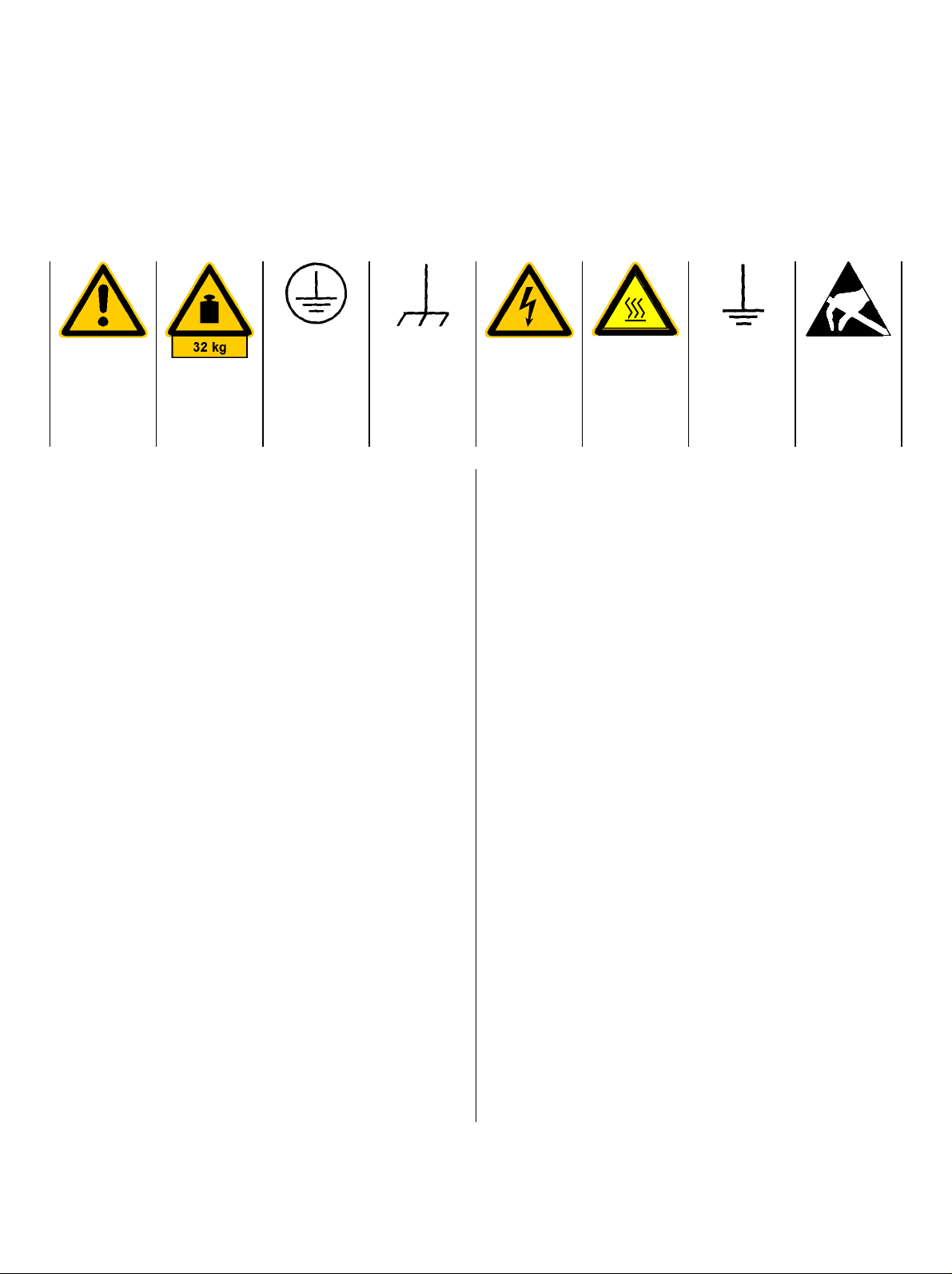
Safety-related symbols used on equipment and documentation from R&S:
Observe
operating
instructions
Weight
indication for
units >18 kg
PE terminal Ground
1. The unit may be used only in the operating conditions and positions specified by the manufacturer. Unless otherwise agreed, the following
applies to R&S products:
IP degree of protection 2X, pollution severity 2
overvoltage category 2, only for indoor use, altitude max. 2000 m.
The unit may be operated only from supply networks fused with max. 16 A.
Unless specified otherwise in the data sheet, a
tolerance of ±10% shall apply to the nominal
voltage and of ±5% to the nominal frequency.
2. For measurements in circuits with voltages V
> 30 V, suitable measures should be taken to
avoid any hazards.
(using, for example, appropriate measuring
equipment, fusing, current limiting, electrical
separation, insulation).
3. If the unit is to be permanently wired, the PE
terminal of the unit must first be connected to
the PE conductor on site before any other c onnections are made. Installation and cabling of
the unit to be performed only by qualified technical personnel.
4. For permanently installed units without built-in
fuses, circuit breakers or similar protective devices, the supply circuit must be fused such as
to provide suitable protection for the users and
equipment.
5. Prior to switching on the unit, it must be ensured
that the nominal voltage set on the unit matches
the nominal voltage of the AC supply network.
If a different voltage is to be set, the power fuse
of the unit may have to be changed accordingly.
terminal
Danger!
Shock hazard
Warning!
Hot surfaces
Ground
6. Units of protection class I with disconnectible
AC supply cable and appliance connector may
be operated only from a power socket with
earthing contact and with the PE conductor connected.
7. It is not permissible to interrupt the PE conductor intentionally, neither in the incoming cable
nor on the unit itself as this may cause the unit
to become electrically hazardous.
Any extension lines or multiple socket outlets
used must be checked for compliance with relevant safety standards at regular intervals.
8. If the unit has no power switch for disconnection
rms
from the AC supply, the plug of the connecting
cable is regarded as the disconnecting device.
In such cases it must be ensured that the power
plug is easily reachable and accessible at all
times (length of connecting cable approx. 2 m).
Functional or electronic switches are not suitable for providing disconnection from the AC
supply.
If units without power switches are integrated in
racks or systems, a disconnecting device must
be provided at system level.
9. Applicable local or national safety regulations
and rules for the prevention of accidents must
be observed in all work performed.
Prior to performing any work on the unit or
opening the unit, the latter must be disconnected from the supply network.
Any adjustments, replacements of parts, maintenance or repair may be carried out only by
authorized R&S technical personnel.
continued overleaf
Attention!
Electrostatic
sensitive devices require
special care
095.1000 Sheet 17

Safety Instructions
Only original parts may be used for replacing
parts relevant to safety (eg power switches,
power transformers, fuses). A safety test must
be performed after each replacement of parts
relevant to safety.
(visual inspection, PE conductor test, insulationresistance, leakage-current measurement, functional test).
10. Ensure that the connections with information
technology equipment comply with IEC950 /
EN60950.
11. Lithium batteries must not be exposed to high
temperatures or fire.
Keep batteries away from children.
If the battery is replaced improperly, there is
danger of explosion. Only replace the battery by
R&S type (see spare part list).
Lithium batteries are suitable for environmentally-friendly disposal or specialized recycling.
Dispose them into appropriate containers, only.
Do not short-circuit the battery.
12. Equipment returned or sent in for repair must be
packed in the original packing or in packing with
electrostatic and mechanical protection.
Electrostatics via the connectors may dam-
13.
age the equipment. For the safe handling and
operation of the equipment, appropriate
measures against electrostatics should be implemented.
14. The outside of the instrument is suitably
cleaned using a soft, lint-free dustcloth. Never
use solvents such as thinners, acetone and
similar things, as they may damage the f ront
panel labeling or plastic parts.
15. Any additional safety instructions given in this
manual are also to be observed.
095.1000 Sheet 18

Supplement A
to Operating Manual
EMI Test Receiver ESPI3 and ESPI7
(Firmware Version 1.72)
Dear Customer,
As far as the functionality of ESPI is conc erned, the following new and modified functions ar e not yet
described in the operating manual.
• Automatic final measurement with THRESHOLD SCAN (page A)
• New status messages (page E)
• Number of sweep points selectable (page F)
• Linear dB scaling (page G)
• Support for Multi Carrier Channel Power measurements (page I)
• Trigger line remains on screen after leaving the TRIG menu (page Z)
• Extended IEC/IEEE bus command (page AA)
• Extended # of frequency points (200 now!) with function SENSe:LIST (page EE)
Automatic Final Measurement with THRESHOLD SCAN
The interference spectrum is first pre-analyzed in a fast prescan to optimize the duration of the
measurement. If the measured level exceeds a lim it line, or violates a margin defined for this line, the
time-consum ing final measurement is performed. T he final measurem ent is, therefore, carried out only
for a reduced number of frequencies of interest. For this measurement, each s c an trac e to be taken into
account has to be assigned a limit line, and the limit line and the limit check function have to be
activated in the LIMIT LINE menu.
The prescan is interrupted immediately for each final measurement to be performed, i.e. the final
measurement immediately follows the prescan measurement. In the case of drifting or fluctuating
interferers, this incr eases the probability that the signal of interest will be reliably detected in the final
measurement.
If the narrowband/broadband discrimination func tion is activated (NB/BB DISCR softkey), the receiver
automatically selects the detector to use in the f inal measurement. T o this end, the receiver compares
the positive and the negative peak value obtained in the prescan. If the difference between the two
values exceeds a user-selected threshold, a broadband interferer is assumed, and the quasi-peak
detector is used in the final measurement. If the difference falls below this threshold, a narrowband
interferer is assumed, and the average detector is used in the final measurement. (The receiver
automatically determines the positive and the negative peak value during the prescan.)
The value obtained in the final measur ement is added to the peak lis t, where it replac es the r esult of the
prescan. W ith NO OF PEAKS, the maximum num ber of peak values to be included in the list can be
defined. If this number is attained, the prescan will be continued, but no fur ther final meas urements will
be performed.
1142.8142.12 A E-4
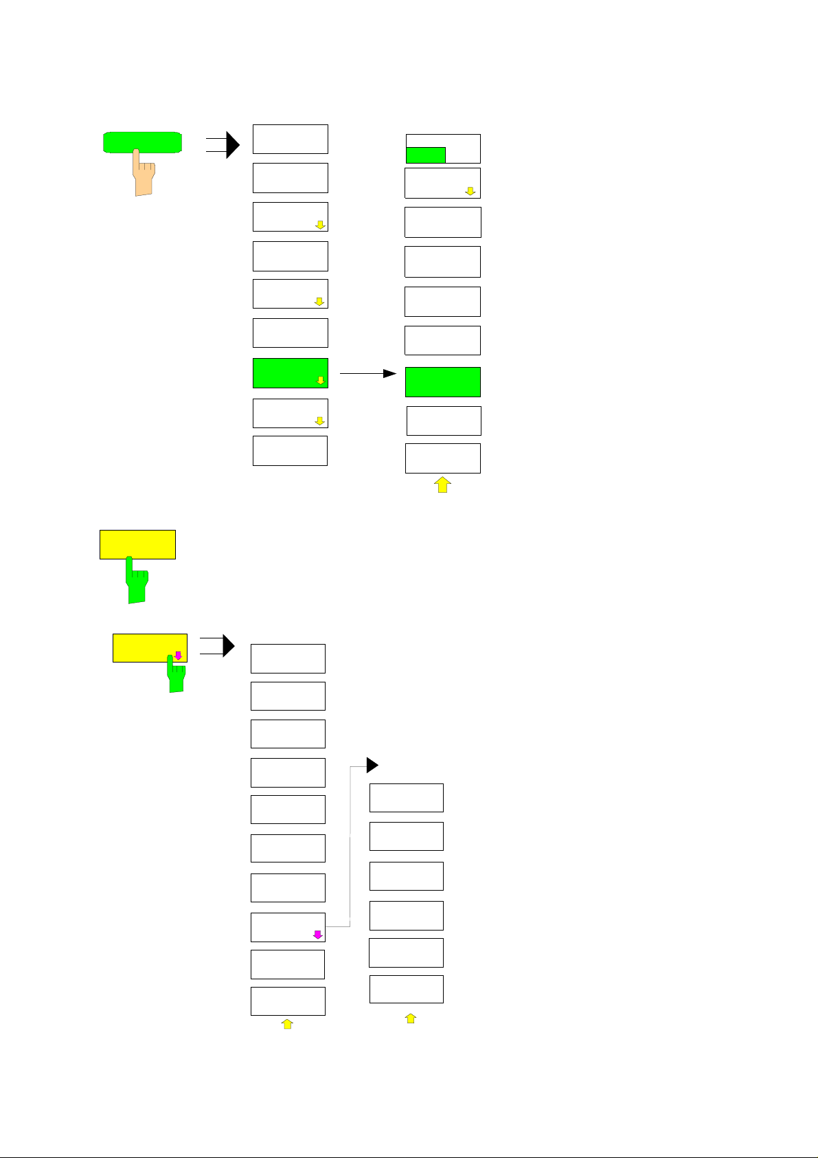
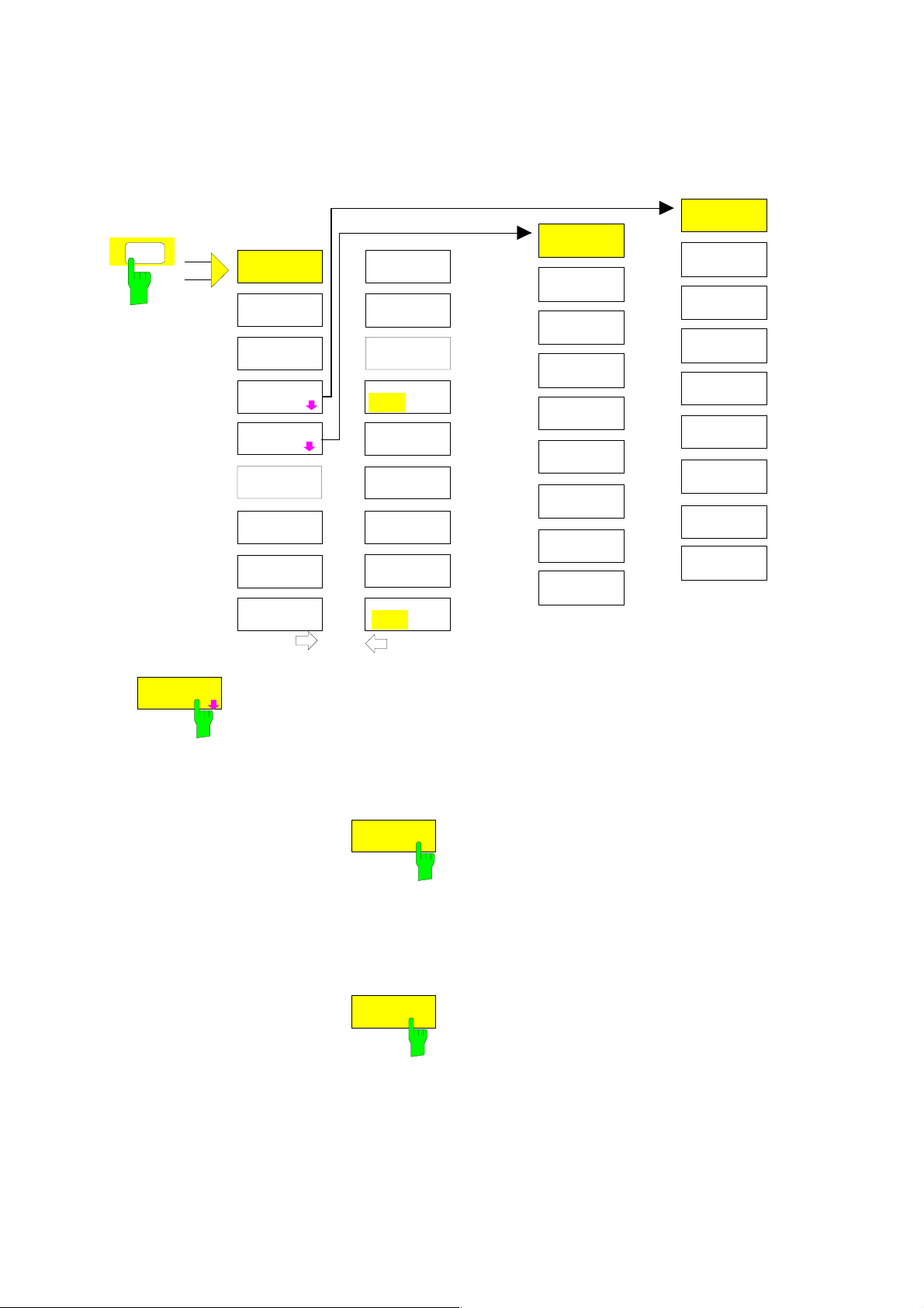
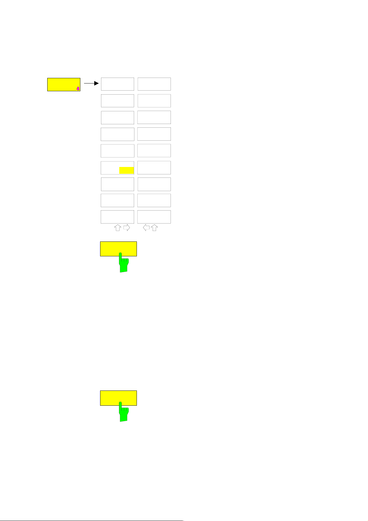
The THRESHOLD SCAN submenu is called from the RECEIVER main menu:
RECEIVER
RECEIVER
FREQUENCY
THRESHOLD
ON OFF
EDIT PEAK
LIST
THRESHOLD
ON OFF
DETECTOR
NO OF
PEAKS
MEAS TIME
NB/BB
DISCR
DEMOD
MARGIN
FINAL
MEAS TIME
THRESHOLD
SCAN
AUTOMATIC
FINAL
FINAL
MEAS
RUN
SCAN
INTER
ACTIVE
RUN
SCAN
The THRESHOLD ON OFF softkey activates or deactivates the
THRESHOLD SCAN measurement function. This function will also be
activated on opening the submenu with the THRESHOLD SCAN softkey
from the RECEIVER main menu.
EDIT PEAK
LIST
EDIT PEAK
LIST
EDIT
FREQUENCY
INSERT
DELETE
SORT BY
FREQUENCY
SORT BY
DELTA LIM
ASCII
EXPORT
ASCII
CONFIG
PAGE UP
PAGE DOWN
The EDIT PEAK LIST softkey calls the
EDIT PEAK LIST submenu used for
editing the peak list.
Further functions relating to the peak
list are described in the operating
manual, section "Data Reduction by
Generating Subrange Maxima".
ASCII
CONFIG
EDIT PATH
DECIM SEP
.,
NEW
APPEND
HEADER
ON OFF
ASCII
COMMENT
1142.8142.12 B E-4

NO OF
PEAKS
With the NO OF PEAKS softkey, you can enter the number of final
measurement peaks to be stored. Numbers between 1 and 500 can be
entered. If the selected number is attained, no further f inal measurements
will be performed.
IEC/IEEE-bus command :CALC:PEAK:SUBR 1...500
NB/BB
DISCR
MARGIN
FINAL
MEAS TIME
AUTOMATIC
FINAL
With the NB/BB DISCR sof tkey, you can enter the decision threshold to
be used by the analyzer to discriminate between broadband and
narrowband interference. Values between 0 dB and 200 dB can be
entered.
IEC/IEEE-bus command --
The MARGIN softkey activates the entry field of the margin, i.e. of an
additional acceptance threshold for the determ ination of the peak lis t. The
limit line currently used is shifted by this am ount for defining the maxim a.
The range of values is -200 dB to 200 dB.
IEC/IEEE-bus command :CALC:PEAK:MARG –200dB...200dB
The FINAL MEAS TIME softkey activates the entry field of the time of final
measurement.
IEC/IEEE-bus command :SWE:TIME:FME <num_value>
The AUTOMATIC FINAL softk ey activates the automatic m ode for the final
measurement, i.e. a final measurem ent will be perf ormed automatically and
immediately each time a value out of limit is detected.
INTER
ACTIVE
IEC/IEEE-bus command --
The INTERACTIVE softkey selects the following sequence for the final
measurement:
• The prescan is interrupted – HOLD SCAN state.
• The bar graph measurement is started in the free running mode.
• The signal can be exactly analyzed by modifying the receiver settings.
• The actual final measurement is started, the receiver settings being
restored except the frequency.
• The current frequency replaces the original one in the frequency list
(drifting interference sources).
• The prescan is continued at the frequency at which it was interrupted....
Note: With the AUTOMATIC FINAL softkey in the CONTINUE
FINAL MEAS submenu a switchover can be made to the
automatic mode before the measurement is started anew.
IEC/IEEE-bus command --
1142.8142.12 C E-4
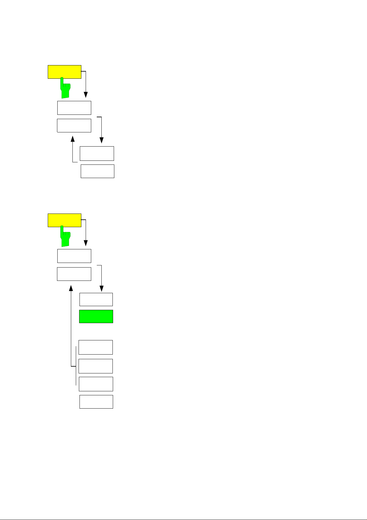
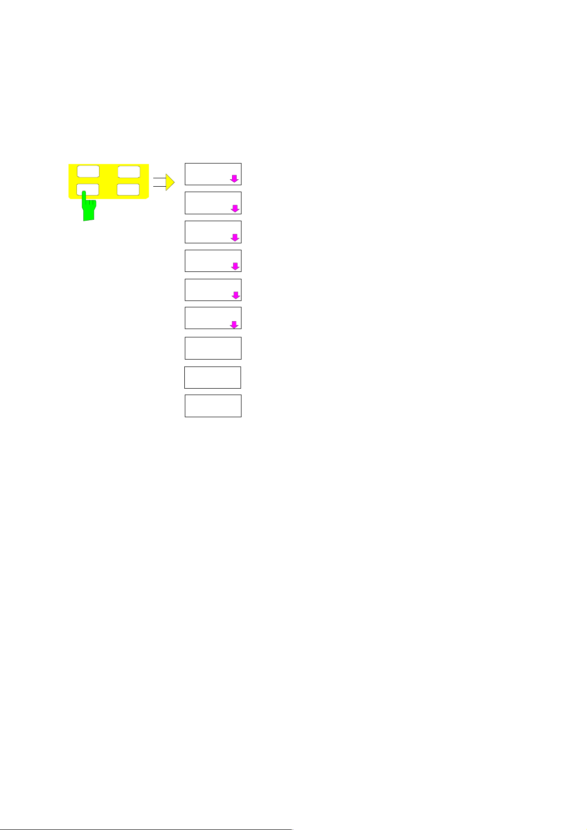
Sequence for AUTOMATIC FINAL:
RUN
SCAN
HOLD
SCAN
STOP
SCAN
HOLD
FINAL MEAS
STOP
FINAL MEAS
Sequence for INTERACTIVE:
RUN
SCAN
HOLD
SCAN
STOP
SCAN
The RUN SCAN softkey starts the pres can. The HOLD SCAN submenu
is called.
If an out-of-limit value is detected, the receiver autom atically goes to the
HOLD SCAN state and starts the final m easurement. The HOLD FINAL
MEAS submenu comes up. On completion of the f inal measurement, the
receiver continues the prescan, and the HOLD SCAN submenu is
displayed again.
The RUN SCAN softkey starts the pres can. The HOLD SCAN submenu
is called.
If an out-of-limit value is detected, the receiver autom atically goes to the
HOLD SCAN state. A submenu with several options for the final
measurement comes up:
• AUTOMATIC FINAL activates the automatic final measurement
mode for the rest of the test run.
• SKIP FREQUENCY skips the final m easurem ent and continues with
the prescan.
AUTOMATIC
FINAL
INTER
ACTIVE
SKIP
FREQUENCY
GET
MAXHOLD
MEASURE
STOP
FINAL MEAS
• GET MAXHOLD accepts the highest level measured during the
HOLD SCAN state as the result of the final measurement and
continues the prescan. (The level value in question is displayed as a
small bar in the bar graph.)
• MEASURE starts the final measurement, the rec eiver settings being
restored except the frequency.
• STOP FINAL MEAS aborts the final measurement and the prescan.
1142.8142.12 D E-4

The table shows a peak list:
EDIT PEAK LIST (Final Measurement Results)
Trace1: 014QP
Trace2: 014AV
TRACE3: ---
TRACE
1 Average
2 Average
1 Quasi Peak
2 Average
1 Quasi Peak
2 Average
1 Quasi Peak
2 Average
1 Quasi Peak
2 Average
1 Quasi Peak
2 Average
2 Average
2 Average
2 Average
1 Quasi Peak
2 Average
1 Quasi Peak
2 Average
2 Average
FREQUENCY
80.0000 MHz
89.4800 MHz
98.5200 MHz
98.5200 MHz
100.7200 MHz
102.3200 MHz
113.2400 MHz
116.9200 MHz
125.8800 MHz
125.8800 MHz
138.4800 MHz
138.4800 MHz
144.0400 MHz
167.0400 MHz
176.2400 MHz
200.4800 MHz
200.4800 MHz
210.2800 MHz
226.5600 MHz
230.0000 MHz
LEVEL dBpT
29.99
35.64
49.94
48.32
55.33
50.86
42.50
44.44
54.91
53.86
41.83
39.38
40.77
44.82
46.56
50.93
48.27
58.71
59.07
46.90
DELTA LIMIT dB
-9.25
-4.09
-0.22
8.15
5.07
10.53
-8.26
3.53
3.68
12.64
-9.81
-2.25
-1.04
2.37
3.87
-2.31
5.02
5.25
15.29
3.05
In the THRESHOLD SCAN mode, with the NB/BB DISCR function active, the receiver automatically
selects the detector to be used in the final measurement on the basis of the results obtained in the
prescan.
New Status Messages/Trace Info
Note: Status message MSG is omitted
#SMPL
Trace-Info:
"#SMPL" indicates that the relation Span / RBW is higher than 125 while
the RMS detector is activated. In this case a stable signal evaluation is
no longer possible due to an insufficient number of A/D converter
samples.
Þ reduce span or increase RBW
Every active measurement curve (trace ≠ BLANK) is allocated trace
information of two or three lines at the left of the diagram. The trace
information has the same color as the measurement curve.
The information on the currently selected trace is displayed in
inverse video (see TRACE - SELECT TRACE softkey).
1142.8142.12 E E-4
Number of Sweep Points Selectable
The SWEEP menu was extended by the SWEEP POINTS softkey.
BW
MEAS
SWEEP
TRIG
CONTINUOUS
SWEEP
SINGLE
SWEEP
CONTINUE
SGL SWEEP
SWEEPTIME
MANUAL
SWEEPTIME
AUTO
SWEEP
COUNT
SWEEP
POINTS
SGL SWEEP
DISP OFF
The SWEEP key calls a m enu in which the sweep
mode is defined. In split-s creen mode, the entries
made are valid for the active window only.
The CONTINUOUS SWEEP, SINGLE SWEEP
and SGL SWEEP DISP OFF sof tkeys are mutually
exclusive selection keys.
SWEEP
POINTS
The SWEEP PO INTS softkey selects the number of measurement sam ples
acquired during a sweep.
The following numbers of points per sweep are available: 125, 251, 501
(default), 1001, 2001, 4001, 8001
Note:
The autopeak detector will be disabled while the number of points per sweep
≠
501.
is
IEC/IEEE-bus command: SWE:POIN 501
1142.8142.12 F E-4
Linear dB scaling
The AMPT menu was extended by the RANGE LINEAR submenu.
AMPT
REF LEVEL
RANGE
LOG 100 dB
RANGE
LOG MANUAL
RANGE
LINEAR
UNIT
RF ATTEN
MANUAL
RF ATTEN
AUTO
REF LEVEL
POSITION
REF LEVEL
OFFSET
GRID
ABS REL
RF INPUT
50Ω 75Ω
dBm
dBmV
dBµV
dBµA
dBpW
VOLT
AMPERE
WATT
RANGE
LINEAR %
RANGE
LINEAR dB
RANGE
LINEAR
The RANGE LINEAR softk ey selects linear s caling for the level display range
of the analyzer. In addition, it opens a submenu for selecting % or dB for the
scaling.
When linear scaling is selected, the % scaling is first activated (see also
RANGE LINEAR dB softkey).
IEC/IEEE-bus command: DISP:WIND:TRAC:Y:SPAC LIN
RANGE
LINEAR %
The RANGE LINEAR % softkey selects linear
scaling in % for the level display range, i.e. the
horizontal lines are labelled in %. The grid is divided
into decades. Markers are displayed in the selected
unit; delta markers ar e dis played in % r ef er enced to
the voltage value at the position of marker 1.
IEC/IEEE-bus command:
DISP:WIND:TRAC:Y:SPAC LIN
RANGE
LINEAR dB
The RANGE LINEAR dB softkey selects linear
scaling in dB for the level display range, i.e. the
horizontal lines are labelled in dB.
Markers are displayed in the selected unit; delta
markers are displayed in dB referenced to the
power value at the position of marker 1.
IEC/IEEE-bus command:
DISP:WIND:TRAC:Y:SPAC LDB
1142.8142.12 G E-4
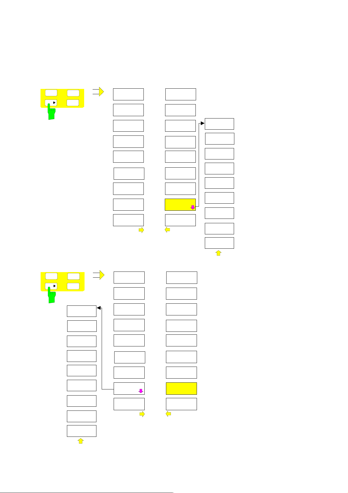
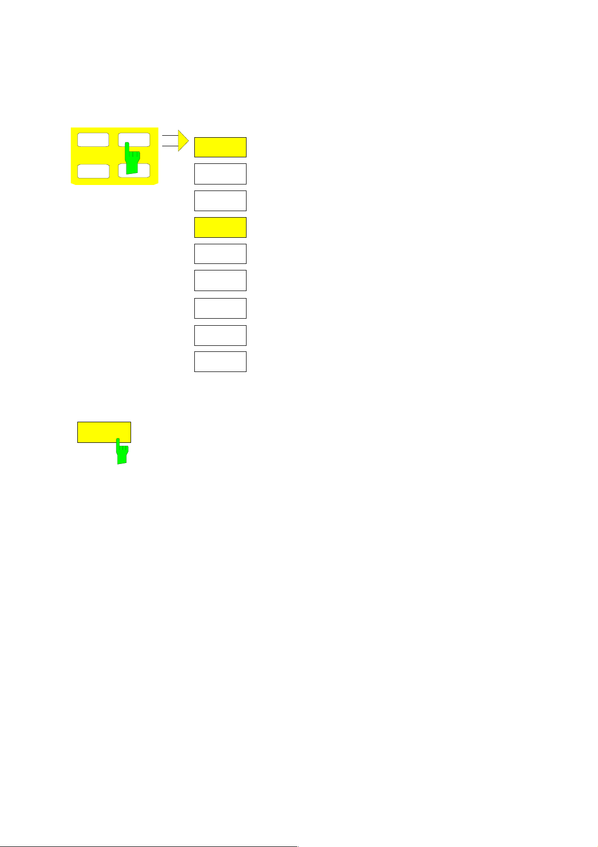
Modified softkey menu MKR->
In the MRK-> menus of Receiver and Analyzer mode, the softkeys NEXT PEAK, NEXT PEAK LEFT ,
NEXT PEAK RIGHT, NEXT MIN, NEXT MIN LEFT, NEXT MIN RIGHT were re-ordered for easier
operation.
Receiver Mode:
SPAN
MKR
AMPL
MKR
FCTN
SELECT
MARKER
PEAK
NEXT PEAK
NEXT PEAK
RIGHT
NEXT PEAK
LEFT
ADD TO
PEAK LIST
TUNE TO
MARKER
MKR -> CF
STEPSIZE
MIN
NEXT
MIN
NEXT MIN
RIGHT
NEXT MIN
LEFT
SETTINGS
COUPLED
LEFT
LIMIT
RIGHT
LIMIT
THRESHOLD
Analyzer Mode:
SPAN
MKR
AMPL
MKR
FCTN
LEFT
LIMIT
RIGHT
LIMIT
THRESHOLD
MARKER
TRACK
MRK->TRACE
SELECT
MARKER
PEAK
CENTER
=MKR FREQ
REF LEVEL
=MKR LVL
NEXT PEAK
NEXT PEAK
RIGHT
NEXT PEAK
LEFT
SEARCH
LIMITS
PEAK
EXCURSION
SEARCH LIM
OFF
MKR->CF
STEPSIZE
MIN
NEXT MIN
NEXT MIN
RIGHT
NEXT MIN
LEFT
PEAK
EXCURSION
SEARCH
LIMITS
EXCLUDE
LO
MRK->TRACE
SEARCH LIM
OFF
1142.8142.12 H E-4
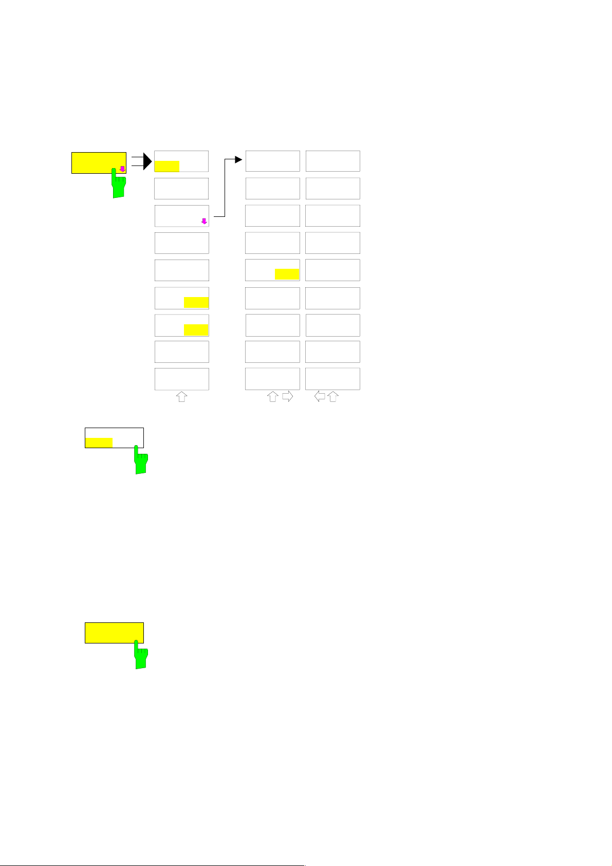
Support for Multi Carrier Channel Power measurements
The MEAS menu was extended by the MULT CARR ACP submenu. In the following, the complete
submenus CHAN PWR ACP and MULT CARR ACP are described. The m odifications are displayed in
bold types.
The MEAS key opens the menu to select and set the power
BW
MEAS
SWEEP
TRIG
TIME DOM
POWER
CHAN PWR
ACP
MULT CARR
ACP
OCCUPIED
BANDWIDTH
SIGNAL
STATISTIC
C/N
C/No
MODULATION
DEPTH
measurement.
The following measurements can be selected:
• Power in time domain (TIME DOM POWER)
Channel power and adjacent-channel power in the
frequency domain with a single carrier
(CHAN PWR ACP)
•••• Channel power and adjacent-channel power in the
frequency domain with several carriers
(MULT CARR ACP)
• Occupied bandwidth (OCCUPIED BANDWIDTH)
• Amplitude probability distribution (SIGNAL STATISTICS)
• Carrier/noise ratio (C/N, C/No)
• Modulation depth (MODULATION DEPTH)
rd
• 3
order intercept (TOI)
TOI
SELECT
MARKER
The above measurements are carried out alternatively.
Channel and Adjacent-Channel Power Measurements
For all channel and adjacent-channel power measurements a specified channel configuration is
assumed which is for instance based on a specific radio communication system.
This configuration is def ined by the nominal channel frequency (= center f requency of the ESPI if only
one carrier is active), the channel bandwidth, the channel spacin g, the adjacent-channel bandwidth
and the adjacent-channel spacing. The ESPI is able to s imultaneously measure the power in up to four
transmission channels and up to three adjacent channels (10 channels: 4 transmission channels,
3 lower and 3 upper adjacent channels).
It offers two methods for channel and adjacent-channel power measurement:
• The integrated bandwidth method (IBW method), i.e. the integration of trace pixels within the
bandwidth of the channel to be measured to the total power of the channel,
• The measurement in time dom ain (Fast ACP) by means of steep resolution filters simulating the
channel.
The two measurements yield the same results. The measurement in time dom ain can be performed
much faster since the complete s ignal is measured within a channel at the same time. W ith the IBW
method, the channel is divided into subspectra. This is done by means of a bandwidth which is small
compared to the channel bandwidth. These subspec tra are then combined by integration of the trace
pixels.
With the IBW me thod, the transm ission channels or adjacent channels ar e mar ked by vertical lines at a
distance of half the channel bandwidth to the left and to the right of the corresponding channel c enter
frequency. The boundaries of the channels are marked by vertical lines. (see Fig. 1).
With the time-domain method, the power versus time is shown for each channel. (see Fig. 2).
For both methods, the results are listed in tables in the lower half of the screen.
1142.8142.12 I E-4

The ESPI offers predefined standard settings which can be selected from a table for the common
mobile radio standards. Thus, channel configuration is performed automatically without the need to
enter the corresponding parameters manually.
For some standards , the channel power and the adjacent-channel power are to be weighted by means
of a root-raised cosine filter corresponding to a receive filter. This type of filtering is switched on
automatically for both methods on selecting the standard (e.g. NADC, TETRA or 3GPP W-CDMA).
Fig. 1 Screen display of adjacent-channel power measurement using the IBW method
Fig. 2 Screen display of adjacent-channel power measurement using the time-domain method
Limit values for the adjac ent-channel power can be defined for the measurement. If limit checking is
switched on, a pass/fail information indicating that the power has been exceeded is dis played during the
measurement in the table in the lower half of the screen.
1142.8142.12 J E-4
Note: With the CP/ACP measurement switched on the functions SPLIT SCREEN and FULL
SCREEN are inhibited.
The channel configuration is def ined in the MEAS - CHAN PWR ACP or the MEAS - MULT CARR ACP
menu.
CHAN POWER
/ACP
CP/ACP
ON OFF
CP/ACP
ON OFF
CP/ACP
STANDARD
CP/ACP
CONFIG
NO. OF
ADJ CHAN
CHANNEL
BANDWIDTH
ADJ CHAN
BANDWIDTH
ACP LIMIT
CHECK
EDIT
ACP LIMIT
The CHAN PWR ACP and MULT
CARR ACP softkeys activate
channel or adjacent-channel
power measurement either fo r a
single carrier signal (CHAN PWR
ACP) or for several carrier
signals (MULT CARR ACP),
SET CP
REFERENCE
SWEEP
TIME
NOISE CORR
NOISE CORR
ON OFF
ON OFF
FULL SIZE
OFF
ON
FAST ACP
DIAGRAM
ADJUST
REF LVL
ADJ CHAN
SPACING
CP/ACP
ABS REL
CHAN PWR
/HZ
SELECT
TRACE
ADJUST
SETTINGS
depending on the current
measurement configuration. In
addition, they open a submenu
for defining the parameters for
channel power measurement.
The softkey selected is shown in
color to indicate that a channel
or adjacent-channel power
measurement is active.
Note: The softkeys are available
only for measurements in
the frequency domain
(span > 0).
The CP/ACP ON/OFF softkey switches calculation of the channel power or
adjacent-channel power on and off.
CP/ACP
STANDARD
With default settings the m easurem ent is perf orm ed by integrating the powers at
the display points within the specified channels (IBW method).
The powers of the adjacent channels are meas ured either as absolute values or
as relative values referenced to the power of a transmission channel. The default
setting is relative-value measurement (see CP/ACP ABS/REL softkey).
When multicarrier ACP measurement is activated, the number of test
points is increased to ensure th at adjacent-channel powers are measured
with adequate accuracy.
IEC/IEEE-bus commands: CALC:MARK:FUNC:POW:SEL CPOW|ACP|MCAC
CALC:MARK:FUNC:POW:RES? CPOW|ACP|MCAC
CALC:MARK:FUNC:POW OFF
The CP/ACP STANDARD softkey opens a table for the selec tion of the settings
according to predefined standards. The test parameters for the channel and
adjacent-channel measurements are set according to the mobile radio standard.
1142.8142.12 K E-4

ACP STANDARD
NONE
NADC IS136
TETRA
PDC
PHS
CDPD
CDMA IS95A FWD
CDMA IS95A REV
CDMA IS95C Class 0 FWD
CDMA IS95C Class 0 REV
CDMA J-STD008 FWD
CDMA J-STD008 REV
CDMA IS95C Class 1 FWD
CDMA IS95C Class 1 REV
W-CDMA 4.096 FWD
W-CDMA 4.096 REV
W-CDMA 3GPP FWD
W-CDMA 3GPP REV
CDMA 2000 DS
CDMA 2000 MC1
CDMA 2000 MC3
TD-SCDMA
The standards available are listed in the
table on the left.
Note: For the ESPI, the channel spacing is defined as the distance between
the center frequency of the adjacent channel and the center frequenc y
of the transmission channel. The definition of the adjacent-channel
spacing in standards IS95 B and C, IS97 B and C and IS98 B and C is
different. These standards define the adjacent-channel spacing from
the center of the transmission channel to the closest border of the
adjacent channel. This definition is also used for the ESPI when the
following standard settings are selected:
CDMA IS95 Class 0 FWD
CDMA IS95 Class 0 REV
CDMA IS95 Class 1 FWD
CDMA IS95 Class 1 REV
The selection of the standard influences the following parameters:
• channel spacing and adjacent-channel spacing
• channel bandwidth, adjacent-channel bandwidth, and type of filtering
• resolution bandwidth
• video bandwidth
• detector
• # of adjacent channels
Trace mathematics and trace averaging are switched off.
The reference level is not influenc ed by the selection of a standard. To achieve
an optimum dynamic range, the reference level has to be set in a way that
places the signal maximum close to the reference level without forcing an
overload message.
The default setting is CP/ACP STANDARD NONE.
IEC/IEEE-bus command: CALC:MARK:FUNC:POW:PRES <standard>
1142.8142.12 L E-4

CP/ACP
CONFIG
See following section "Setting the Channel Configuration"
SET CP
REFERENCE
SWEEP
TIME
NOISE CORR
ON OFF
With channel power measurement activated, the SET CP REFERENCE softkey
defines the currently measured channel power as the reference value. The reference
value is displayed in the CH PWR REF field; the default value is 0 dBm.
In adjacent-channel power measurement with one or several carrier
signals, the power is always referenced to a transmission ch annel, i.e. no
value is displayed for CH PWR REF.
IEC/IEEE-bus command: POW:ACH:REF:AUTO ONCE
The SWEEP TIME softk ey activates the entry of the sweep time. W ith the RMS
detector, a longer sweep time increases the stability of the measurement results.
The function of the sof tkey is identical to the sof tkey SWEEP TIME MANUAL in
the menu BW.
IEC/IEEE-bus command: SWE:TIM <value>
If the NOISE CORR ON/OFF softkey is activated, the res ults will be c orr ec ted by
the instrument's inherent noise, which increases the dynamic range.
When the function is switched on, a refer ence measurem ent of the instrum ent's
inherent noise is carried out. The nois e power meas ured is then subtr acted from
the power in the channel that is being examined.
The inherent noise of the instrument depends on the selected center f requency,
resolution bandwidth and level setting. Therefore, the correction function is
disabled whenever one of these parameters is changed. A disable message is
displayed on the screen.
To enable the correction function in conj unction with the changed setting, press
the softkey once more. A new reference measurement is carried out.
IEC/IEEE-bus command: SENS:POW:NCOR ON
1142.8142.12 M E-4

FAST ACP
ON OFF
The FAST ACP softkey switches between the IBW m ethod (FAST ACP OFF) and
the time domain method (FAST ACP ON).
With FAST ACP ON the power measurement is perform ed in the differ ent channels
in the time domain. The ESPI sets the center frequency consecutively to the different
channel center frequencies and measures the power with the selected measurement
time (= sweep time/number of channels) . The RBW filter s suitable for the selected
standard and frequency offset are autom atically used (e.g. root raised cos with IS
136). The list of available channel filters is inc luded in section "Setting of Bandwidths
and Sweep Time – BW key".
The RMS detector is used for obtaining correct power measurement results.
Therefore this requires no software correction factors.
Measured values are output as a list. The powers of the transmission
channels are output in dBm, th e powers of the ad jacent channels in dBm
(CP/ACP ABS) or dB (CP/ACP REL).
The sweep time is selected depending on the des ired reproducibility of results.
Reproducibility increases with sweep time since power measurement is then
performed over a longer time period.
As a general approach, it can be assumed that approx. 500 non-correlated
measured values are required for a reproducibility of 0.5 dB (99% of the
measurements are within 0.5 dB of the true m eas ured value). T his holds true f or
white noise. The measured values ar e considered as non-c orrelated when their
time interval corresponds to the reciprocal of the measured bandwidth.
With IS 136 the measurement bandwidth is approx. 25 kHz, i.e. measured
values at an interval of 40 µs are considered as noncorrelated. A measurem ent
time of 20 ms is thus required per c hannel f or 1000 measured values. This is the
default sweep time which the ESPI sets in coupled mode. Approx. 5000
measured values are required for a reproducibility of 0.1 dB (99%), i.e. the
measurement time is to be increased to 200 ms.
IEC/IEEE-bus command SENS:POW:HSP ON
FULL SIZE
DIAGRAM
ADJUST
REF LVL
The FULL SIZE DIAGRAM softkey switches the diagram to full screen size.
IEC/IEEE-bus command: DISP:WIND1:SIZE LARG|SMAL
The ADJUST REF LVL softkey adjusts the reference level of the ESPI to the
measured channel power. This ensures that the settings of the RF attenuation
and the reference level are optimally adjusted to the signal level without
overloading the ESPI or limiting the dynamic range by a too small S/N ratio.
Since the measurement bandwidth for channel power measurements is
significantly lower than the signal bandwidth, the signal path may be overloaded
although the trace is still significantly below the reference level.
IEC/IEEE-bus command: SENS:POW:ACH:PRES:RLEV
For manual setting of the test par ameters different f r om the settings made with ADJ UST SETTI NGS the
following should be observed:
1142.8142.12 N E-4

Frequency span The frequency span must at leas t cover the channels to be meas ured plus
a measurement margin of 10%.
For channel power measurement, the span is 1.1 x channel bandwidth.
Note: If the frequency span is large in comparison with the channel
bandwidth (or the adjacent-channel bandwidths) being examined, only a
few points on the trace are available per channel. This reduces the
accuracy of the waveform calc ulation for the channel filter used, which has
a negative effect on the measurement accuracy.
We therefore strongly recommend that the formulas mentioned be taken
into consideration when selecting the frequency span.
Resolution bandwidth (RBW)
To ensure both an acceptable measurement speed and the required
selection (to suppress spectral components outside the channel to be
measured, especially of the adjacent channels), the resolution bandwidth
must not be selected too sm all or too large. As a general approach, the
resolution bandwidth is to be set to values between 1% and 4% of the
channel bandwidth.
A larger resolution bandwidth can be selected if the spectrum within the
channel to be measured and around it has a flat characteristic. In the
standard setting, e.g. for standard IS95A REV at an adjacent channel
bandwidth of 30 kHz, a resolution bandwidth of 30 k Hz is us ed. T his yields
correct results since the spectrum in the neighborhood of the adjacent
channels normally has a constant level. For standard NADC/IS136 this is
not possible for example, since the spectrum of the transmit signal
penetrates into the adjacent channels and a too large res olution bandwidth
causes a too low selection of the channel filter. The adjacent-channel
power would thus be measured too high.
With the exc eption of the IS95 CDMA standards, the ADJUST SETTINGS
softkey sets the resolution bandwidth (RBW ) as a function of the channel
bandwidth:
RBW ≤ 1/40 of channel bandwidth.
The maximum possible resolution bandwidth (with respect to the
requirement RBW ≤ 1/40) resulting from the available RBW steps (1, 3) is
selected .
Video bandwidth (VBW ) For a correct power m easurement, the video signal mus t not be limited in
bandwidth. A restricted bandwidth of the logarithmic video signal would
cause signal averaging and thus result in a too low indication of the power
(-2.51 dB at very low video bandwidths). The video bandwidth should
therefore be selected at least three times the resolution bandwidth.
The ADJUST SETTINGS softkey sets the video bandwidth (VBW) as a
function of the channel bandwidth as follows:
VBW ≥ 3 × RBW.
The smallest possible VBW with regard to the available step size will be
selected.
Detector The ADJUST SETTINGS softkey selects the RMS detector.
The RMS detector is selected since it correctly indicates the power
irrespective of the character ist ics of the s ignal to be measured. In principle,
the sample detector would be possible as well. Due to the limited num ber
of trace pixels used to calculate the power in the channel, the sample
detector would yield less stable results. Averaging, which is often
performed to stabilize the measurement results, leads to a too low level
indication and should therefore be avoided. T he reduction in the displayed
power depends on the number of averages and the signal characteristics in
the channel to be measured.
1142.8142.12 O E-4
Setting the Channel Configuration
MEAS - CP/ACP CONFIG submenu:
CP/ACP
CONFIG
NO. OF
ADJ CHAN
NO. OF
TX CHAN
CHANNEL
BANDWIDTH
CHANNEL
SPACING
ACP REF
SETTINGS
CP/ACP
ABS REL
CHAN PWR
/HZ
ADJUST
SETTINGS
NO. OF
ADJ CHAN
ACP LIMIT
CHECK
EDIT
ACP LIMIT
The CP/ACP CONFIG softkey opens a submenu
for configuration of the c hannel power and adjacent
channel power measurement independently of the
offered standards.
The channel configuration includes the number
of channels to be measured, the channel
bandwidths (CHANNEL BANDWIDTH), and the
channel spacings (CHANNEL SPACING).
Limit values can additionally be specified for the
adjacent-channel power (ACP LIMIT CHECK and
EDIT ACP LIMITS) which are checked for
compliance during the measurement.
SELECT
TRACE
The NO. OF ADJ CHAN softkey activates the entry of the
number ±n of adjacent channels to be considered in the
adjacent-channel power measurement.
Numbers from 0 to 3 can be entered.
NO. OF
TX CHAN
The following measurements are performed depending on the
number of the channels.
0 Only the channel powers are measured.
1 T he channel powers and the power of the upper and lower
adjacent channel are measured.
2 The channel powers, the power of the upper and lower
adjacent channel and of the next higher and lower channel
(alternate channel 1) are measured.
3 The channel power, the power of the upper and lower
adjacent channel, the power of the next higher and lower
channel (alternate channel 1) and of the next but one
higher and lower adjacent channel (alternate channel 2)
are measured.
IEC/IEEE-bus command: POW:ACH:ACP 1
The NO. OF TX CHAN softkey enables the entry of the
number of carrier signals to be considered in channel and
adjacent-channel power measurements.
Numbers from 1 to 4 can be entered.
The softkey is available only for multicarrier ACP
measurements.
IEC/IEEE-bus command: SENS:POW:ACH:TXCH:COUN 4
1142.8142.12 P E-4

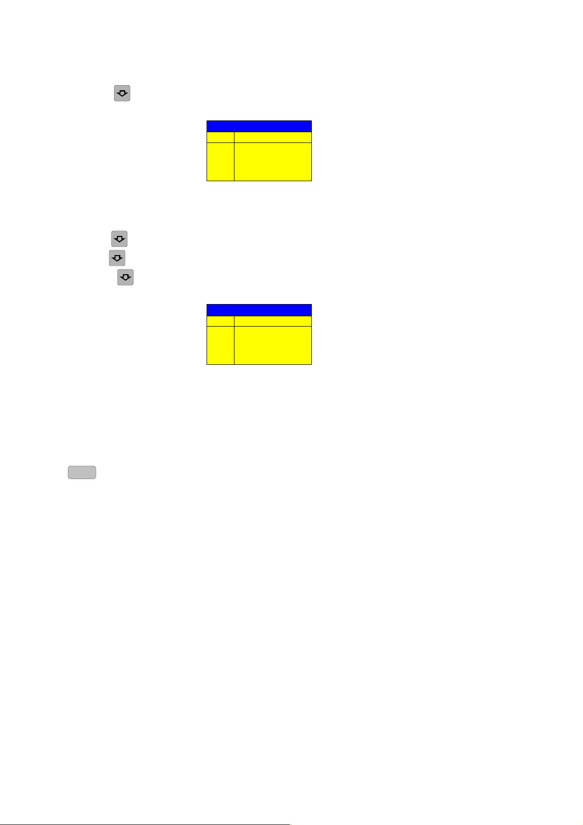
CHANNEL
BANDWIDTH
The CHANNEL BANDWIDTH softk ey opens a table for defining
the channel bandwidths for the transmission channels and the
adjacent channels.
ACP CHANNEL BW
CHAN BANDWIDTH
ADJ 14 kHz
ALT1 14 kHz
ALT2 14 kHz
The transmission-c hannel bandwidth is normally defined by the
transmission standard. The correct bandwidth is set
automatically for the selected standard (see CP/ACP
STANDARD softkey).
With the IBW m ethod (FAST ACP O FF), the channel bandwidth
limits are marked by two vertical lines right and left of the
channel center frequency. It can in this way be visually checked
whether the entire power of the signal under test is within the
selected channel bandwidth.
Measurements in the time domain (FAST ACP ON) are
performed in the zero span mode. The channel limits are
indicated by vertical lines. For measurements requiring
channel bandwidths deviating from those defined in the
selected standard the IBW method is to be use d.
Refer to section "Setting of Bandwidths and Sweep Time –
BW key" for a list of available channel filters.
When measuring according to the IBW method (FAST ACP
OFF) the bandwidths of the different adjacent channels ar e to be
entered numerically. Since all adjacent channels of ten have the
same bandwidth, the other channels Alt1 and Alt2 are set to the
bandwidth of the adjacent channel on entering the adjacentchannel bandwidth (ADJ). Thus only one value needs to be
entered in case of equal adjacent channel bandwidths. The
same holds true for the ALT2 channels (alternate channels 2)
when the bandwidth of the ALT1 channel (alternate channel 1) is
entered.
Note: The bandwidths can be set separately by overwr iting
the table from top to bottom.
IEC/IEEE-bus command: SENS:POW:ACH:BWID:CHAN 14kHz
SENS:POW:ACH:BWID:ACH 1kHz
SENS:POW:ACH:BWID:ALT1 14kHz
SENS:POW:ACH:BWID:ALT2 14kHz
1142.8142.12 Q E-4
CHANNEL
SPACING
The CHANNEL SPACING softkey opens a table for defining the
channel spacings.
ACP CHANNEL SPACING
CHAN SPACING
ADJ 20 kHz
ALT1 40 kHz
ALT2 60 kHz
Since all the adjacent channels often have the same distance to
each other, the entry of the adjacent-channel spacing (ADJ)
causes channel spacing ALT1 to be set to twice and channel
spacing ALT2 to three times the adj ac ent-c hannel s pacing. Thus
only one value needs to be entered in case of equal channel
spacing. The same holds true for the ALT2 channels when the
bandwidth of the ALT1 channel is entered.
Note: The channel spacings can be set separately by
overwriting the table from top to bottom.
IEC/IEEE-bus command: SENS:POW:ACH:SPAC:CHAN 20kHz
SENS:POW:ACH:SPAC:ACH 20kHz
SENS:POW:ACH:SPAC:ALT1 40kHz
SENS:POW:ACH:SPAC:ALT2 60kHz
ACP REF
SETTINGS
The ACP REF SETTINGS softkey opens a table for selecting
the transmission channel to which the adjacent-channel
relative power values should be referenced.
ACP REFERENCE CHANNEL
TX CHANNEL 1
TX CHANNEL 2
TX CHANNEL 3
TX CHANNEL 4
MIN POWER TX CHANNEL
MAX POWER TX CHANNEL
LOWEST & HIGHEST CHANNEL
TX CHANNEL 1 - 4 Selection of one of channels 1 to 4.
MIN POWER
TX CHANNEL
The transmission channel with the
lowest power is u sed as a reference
channel.
MAX POWER
TX CHANNEL
The transmission channel with the
highest power is used as a
reference channel.
LOWEST & HIGHEST
CHANNEL
The outer lefthand transmission
channel is the reference channel for
the lower adjacent channels, the
outer righthand transmission
channel that for the upper adjacent
channels.
IEC/IEEE-bus command:
SENS:POW:ACH:REF:TXCH:MAN 1
SENS:POW:ACH:REF:TXCH:AUTO MIN
1142.8142.12 R E-4

CP/ACP
f
ABS REL
The CP/ACP ABS/REL softkey (channel power absolute/relative)
switches between absolute and relative power measurem ent in
the channel.
CP/ACP ABS The absolute power in the transmiss ion channel
and in the adjacent channels is dis played in the
unit of the Y axis, e.g. in dBm, dBµV.
CP/ACP REL For adjacent-c hannel power measur ements (NO.
OF ADJ CHAN > 0), the level of the adjacent
channels is displayed relative to the level of the
transmission channel in dBc.
For channel power measurem ents (NO. OF ADJ
CHAN = 0) with a single carrier, the power of
the transmission channel is displayed relative to
the power of a reference channel defined by SET
CP REFERENCE. This means:
1. Declare the power of the currently measur ed
channel as the reference value, using the
SET CP REFERENCE softkey.
2. Select the channel of interest by varying the
channel frequency (ESPI center frequency).
With linear s caling of the Y axis, the power of the
new channel relative to the reference channel
(CP/CP
logarithmic ratio 10lg (CP/CP
) is displayed. With dB scaling, the
re
) is displayed.
ref
The relative channel power measurement can
thus also be used for universal adjacent-channel
power measurements. Each channel can be
measured individually.
CHAN PWR
/HZ
IEC/IEEE-bus command: SENS:POW:ACH:MODE ABS
The CHAN PWR / HZ softkey toggles between the
measurement of the total c hannel power and the measurement
of the channel power referenced to a 1-Hz bandwidth.
The conversion factor is
10 lg
⋅
Channel Bandwidth
1
⋅
.
By means of this function it is possible e.g. to measure the
signal/noise power density or use the additional functions
CP/ACP REL and SET CP REFERENCE to obtain the signal to
noise ratio.
IEC/IEEE-bus command:
CALC:MARK:FUNC:POW:RES:PHZ ON|OFF
1142.8142.12 S E-4

ADJUST
SETTINGS
The ADJUST SETTINGS softkey automatically optimizes the
instrument settings for the selected power measurement (see
below).
All instrument settings relevant f or a power m easurem ent within
a specific frequency range (channel bandwidth) are optimized for
the selected channel configuration (c hannel bandwidth, channel
spacing):
• Frequency span:
The frequency span should cover at leas t all channels to be
considered in a measurement.
For channel power measurem ents, the f requency span is set
as follows:
(No. of transmission channels - 1) ×
× transmission
× ×
channel spacing + 2 x transmission channel band width +
measurement margin
For adjacent-channel power measurements,
the frequency span is set as a function of the number of
transmission channels, the transmission channel
spacing, the adjacent-channel spacing, and the
bandwidth of one of adjacent-channels ADJ, ALT1 or
ALT2, whichever is furthest away from the transmission
channels:
×
(No. of transmission channels - 1)
channel spacing + 2
× (
× (adjacent-channel spacing +
× (× (
× transmission
× ×
adjacent-channel bandwidth) + measurement margin
The measurement margin is approx. 10% of the value
obtained by adding the channel spacing and the channel
bandwidth.
• Resolution bandwidth RBW ≤ 1/40 of channel bandwidth
• Video bandwidth VBW ≥ 3 × RBW
• Detector RMS detector
Trace math and trace averaging functions are switched off.
The reference level is not influenced by
can be separately adjusted with
ADJUST REF LVL.
ADJUST SETTINGS. It
The adjustment is carried out only once; if necessary, the
instrument settings can be changed later.
IEC/IEEE-bus command:
SENS:POW:ACH:PRES ACP|CPOW|MCAC|OBW
1142.8142.12 T E-4
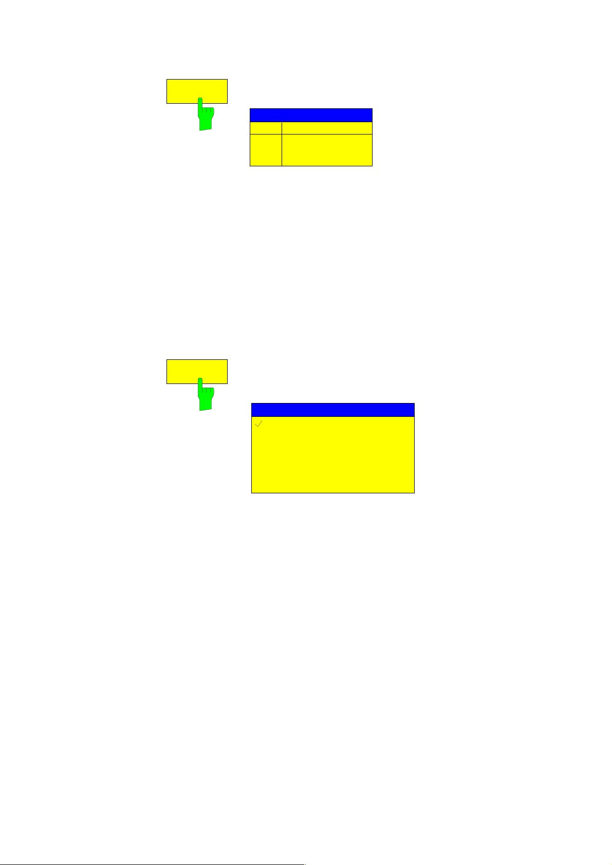
ACP LIMIT
CHECK
The ACP LIMIT CHECK softk ey switches the limit check f or the
ACP measurement on and off.
EDIT
ACP LIMITS
IEC/IEEE-bus command:
CALC:LIM:ACP ON
CALC:LIM:ACP:ACH:RES?
CALC:LIM:ACP:ALT:RES?
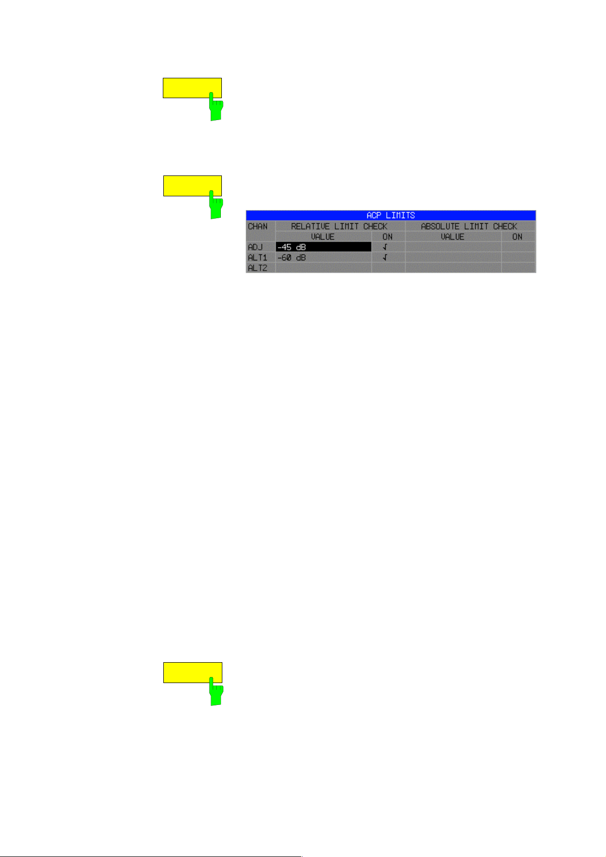
The EDIT ACP LIMITS softkey opens a table for defining the
limits for the ACP measurement.
The following rules apply for the limits:
• A separate limit can be defined for each adjacent channel.
The limit applies to both the upper and the lower adjacent
channel.
• A relative and/or absolute limit can be defined. The check of
both limit values can be activated independently.
• The ESPI checks adherence to the limits irrespective of
whether the limits are absolute or relative or whether the
measurement is carr ied out with absolute or relative levels. If
both limits are active and if the higher of both lim it values is
exceeded, the measured value is marked accordingly.
SELECT
TRACE
Note: Measured values exceeding the limit are marked by a
preceding asterisk.
IEC/IEEE-bus command:
CALC:LIM:ACP ON
CALC:LIM:ACP:ACH 0dB,0dB
CALC:LIM:ACP:ACH:STAT ON
CALC:LIM:ACP:ACH:ABS –10dBm,-10dBm
CALC:LIM:ACP:ACH:ABS:STAT ON
CALC:LIM:ACP:ALT1 0dB,0dB
CALC:LIM:ACP:ALT1:STAT ON
CALC:LIM:ACP:ALT1:ABS –10dBm,-10dBm
CALC:LIM:ACP:ALT1:ABS:STAT ON
CALC:LIM:ACP:ALT2 0dB,0dB
CALC:LIM:ACP:ALT2:STAT ON
CALC:LIM:ACP:ALT2:ABS –10dBm,-10dBm
CALC:LIM:ACP:ALT2:ABS:STAT ON
The SELECT TRACE softkey selects the trace on which the
CP/ACP measurement is to be perform ed. Only activated traces
can be selected, i.e. traces not set to BLANK.
IEC/IEEE-bus command:
SENS:POW:TRAC 1
1142.8142.12 U E-4

Examples:
1. Measurement of adjacent-channel power for a specific standard:
The adjacent-channel power is to be m easured for a signal at 800 MHz with 0 dBm level in line with
IS136.
PRESET] Set the ESPI to the default setting.
[
FREQ: CENTER: 800 MHz] Set the center frequency to 800 MHz.
[
AMPT: 0 dBm] Set the reference level to 0 dBm.
[
MEAS] Call the menu for the measurement functions.
[
[
CHAN PWR / ACP] Select the channel and adjacent-channel power m easurem ent function.
The measurem ent is perf orm ed with the default settings or a previously
defined setting. The subm enu for setting the desir ed new configuration
is opened.
CP/ACP STANDARD:
[
select IS136:
[
CP/ACP CONFIG] Call the submenu for configuration of the adjacent-channel power
ENTER] Select the NADC (IS136) standard.
measurement.
[
NO. OF ADJ CHAN:
ENTER] Select two adjacent channels for the measurement, i.e. the adjacent
2
channel and the alternate channel are measured.
[
ADJUST SETTINGS] Set the optimum span, resolution bandwidth (RBW), video bandwidth
(VBW) and detector automatically for the measurement. The absolute
channel power and the relative power of the adjacent channels are
displayed on the screen.
PREV
[
ADJUST REF LVL] Set the reference level equal to the channel power measured.
Change to the main menu for channel power measurement.
2. Measurement with user-specific channel configuration:
Measurement of the adjac ent-channel power ratio (ACPR) of an IS95 CDMA signal at 800 MHz, level
0 dBm. Similar to example 1, the setting can be simplified by using
PRESET] Set the ESPI to the default setting.
[
FREQ: CENTER: 800 MHz] Set the center frequency to 800 MHz.
[
AMPT: 0 dBm] Set the reference level to 0 dBm.
[
MEAS] Call the menu for the measurement functions.
[
[
CHAN PWR / ACP] Select the channel and adjacent-channel power m easurem ent function.
CP/ACP STANDARD.
The measurem ent is c arried out with the default s ettings or a previous ly
defined setting. The subm enu for setting the desir ed new configuration
is opened.
CP/ACP CONFIG] Call the submenu for defining the channel configuration.
[
[
NO. OF ADJ CHAN:
ENTER] Select two adjacent channels for the measurement, i.e. the adjacent
2
channel and the alternate channel are measured.
1142.8142.12 V E-4
CHANNEL BANDWIDTH:
[
1.23
MHz: : 30 kHz] Set the channel bandwidt h to 1.23 MHz in accordance with IS 95.
Set the adjacent-channel bandwidth to 30 kHz.
TX/ACP CHANNEL BW
CHAN BANDWIDTH
TX 1.23 MHz
ADJ 30 kHz
ALT1 30 kHz
ALT2 30 kHz
Upon entry of 30 kHz for the adjacent channel the alternate c hannels
are also set to 30 kHz.
[CHAN SPACING:
1.25
MHz:
885 kHz: :
-1.98
MHz] :
MHz] Open the list for entering the channel spacings.
2.97
TX/ACP CHAN SPACING
CHAN SPACING
TX 1.25 MHz
ADJ 885 kHz
ALT1 1.98 MHz
ALT2 2.97 MHz
Upon entry of 885 kHz for the adjacent channel the channels ALT1 and
ALT2 are set to 1770 kHz and 2655 kHz. Upon entry of 1.98 MHz for
the alternate channel 1 the alternate channel 2 is set to 2.97 MHz.
ADJUST SETTINGS] Automatically set the optimum span (= 5 MHz), resolution bandwidth
[
(RBW = 30 kHz), video bandwidth (VBW = 300 kHz) and detector
(RMS) for the measurement. The absolute channel power and the
relative power of the adjacent channels and alternate channels are
displayed on the screen.
PREV
[
ADJUST REF LVL] Set the reference level equal to the channel power measured.
Go to the main menu for channel power measurement.
3. Measurement of signal/noise power density (C/No) of an IS95 CDMA signal
(frequency 800 MHz, level 0 dBm)
[PRESET] Set the ESPI to the default setting.
FREQ: CENTER: 800 MHz] Set the center frequency to 800 MHz.
[
AMPT: 0 dBm] Set the reference level to 0 dBm.
[
MEAS] Call the menu for the measurement functions.
[
CHAN PWR / ACP] Select the channel and adjacent-channel power measurement. The
measurement is performed with the default setting or a previously
defined setting. The subm enu for setting the desir ed new configuration
is opened.
CP/ACP CONFIG] Call the submenu for defining the channel configuration.
[
[
NO. OF ADJ CHAN:
ENTER] Do not select an adjacent channel for the measurement, i.e. the
0
measurement is carried out in one channel only.
1142.8142.12 W E-4

CHANNEL BANDWIDTH:
[
MHz] Set the channel bandwidth to 1.23 MHz in line with IS95.
1.23
[
ADJUST SETTINGS] Set the optimum span (= 5 MHz), resolution bandwidth (RBW = 30
kHz), video bandwidth (VBW = 300 kHz) and detector (RMS) for the
measurement automatically. The absolute channel power and the
relative power of the adjacent channels and alternate channels are
displayed on the screen.
PREV
[
ADJUST REF LVL] Set the reference level equal to the channel power measured.
[
SET CP REFERENCE] Set the measured channel power as a reference for the subsequent
Go to the main menu for channel power measurement
measurements.
[
CP/ACP ABS / REL] Select relative measurement related to the reference power set with
SET REFERENCE (result 0 dB).
[
CHAN PWR / HZ] Select power measurement related to 1 Hz bandwidth (result -60.9 dB).
FREQ: CENTER: 805 MHz] Set the center frequenc y to 805 MHz. The ESPI measures the channel
[
power at 1.23 MHz bandwidth and outputs the result in dB relative to the
reference power and 1 Hz bandwidth.
1142.8142.12 X E-4
 Loading...