

Page 1

ICS Regent
®
PD-6003
Real-Time Clock Communications Modules
RS232 Communications and Battery-Backed
Real-Time Clock
(T3151)
Issue 1,
Real-time clock communications modules provide a serial
communications interface between the controller and e
equipment. The module also provides battery-backed real
time information to the controller and applications programs.
Real-time clock communications modules are recommended
for applications that perform sequence of events recording or
process historian data collection.
March, 06
xternal
-
Features
•
Battery-backed real-time clock.
·
Date format: Month-day-year.
·
Time format: Hours:minutes:seconds:milliseconds.
·
One millisecond resolution.
·
Two serial ports per module.
·
Supports RS-232 standards.
·
Hot Replaceable.
·
Front panel indicators on each module show communi
status and transmit/receive activity.
·
TÜV certified for safety, Risk Class 5.
Module Operation
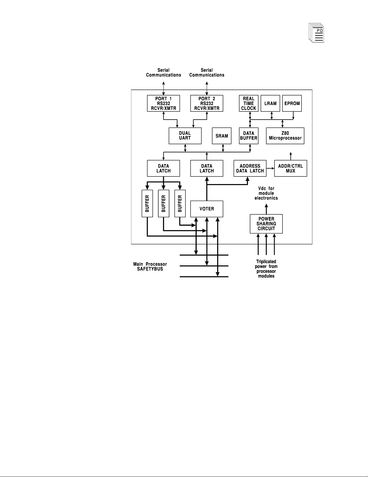
Figure 1 shows a block diagram
communications module.
cations
of the real-time clock
Industrial Control Services
1
Page 2

Real-Time Clock Communications Modules
(T3151)
Each real-time clock communications module has a Z80 micro
processor, a PROM containing all of the module’s executable
software, static RAM containing program variables, the real
time clock, shared RAM for transferring information between
the processor modules and the communications module’s
microprocessor, and a dual-channel UART with RS-232 serial
port interfaces. Both the clock and the static RAM are
battery-backed. If the system is powered down the batter
y
continues to keep the clock running. The microprocessor
reads the time, checks it for consistency, and then transfers it
to the shared RAM where it can be read by the processor
modules.
Each communications module receives power from all three of
the processor modules. A power-sharing circuit in each of the
communications modules receives the power from the three
processor modules and combines it through a diode OR power
sharing circuit. This ensures that if one processor module's
power supply fails, th
e communications module will continue
to operate by drawing power from the two remaining power
supplies, and the system's communications functions are
maintained.
-
-
The Dual UART (universal asynchronous receiver/trans
mitter) buffers incoming and outgoing communications
characters. The triplicated processor modules interrupt once
every millisecond to read characters from or write characters
to the communications module.
2
Industrial Control Services
Page 3
Real-Time Clock Communications Modules
(T3151)
PD-6003
Mar-06
Figure 1. Block Diagram of Real-Time Clock
Communications Module.
When the processor modules read characters from the
communications module, the communications module sends
characters through triplicated bus drivers to the processor
Safetybus. The processor modules vote this triplicated data
and perform communications processing. When the processor
modules write data to the communications module, the
triplicated data is voted by the communications modules and
sent to the dual UART where it is then transmitted out the
associated port.
The communications modules’ two serial ports operate
independently and can both be configured differently to
support a wide variety of functions including Regent R2
3
Page 4

Real-Time Clock Communications Modules
(T3151)
protocol, Modbus protocol, ASCII output, and Guarded Peer
Link communications. The
W
INTERPRET
application is used
-
to configure the appropriate port functions and specify baud
rate, data format, parity, and node number.
Once each application program scan the processors modules
read the real-time clock data from the module. The real-time
clock informati
on is placed on the Safetybus from three
independently controlled buffers, preventing failures in the
real-time clock communications module from propagating into
the system.
When the processor modules set the real-time clock, all real
time clock communications modules that are installed in the
system are simultaneously set. After setting the real-time
clocks, the processor modules read real-time clock values from
the left-most installed communications module. If the left
most real-time clock communication
s module is faulted, the
-
processor modules will then read real-time clock values from
the next real-time clock communications module to the right.
Testing and Diagnostics
The modules triplicated Safetybus interface ensures that no
failure in the module will effect the operation of the Regent
system or other module. Extensive fault detection and
annunciation of critical redundant circuits helps ensure that
processors will not accept erroneous data from a faulty
module.
Each type of communications module has a unique
identification code that is read by the controller. This code
lets the controller know what type of module is installed in
each communications slot. If a module is removed and
replaced with a module of a different type the processors will
indicate a COMM error.
The processor modules perform background diagnostic checks
on the module to test bus driver circuits and check the
communications module ID codes. Clock values are checked
for bad data. Communications message format, framing,
checksum,
the processor modules’ normal communications processing.
and other communications errors are checked by
4
Industrial Control Services
Page 5

Real-Time Clock Communications Modules
(T3151)
Failures result in a COMM module error indication at the
processor modules and an RTC/COMM error at the
communications module.
Front Panel
Figure 2 shows the physical features of the real-time clock
communications modules. The front panel of each module
contains indicators showing overall module health, transmit
and receive status, and backup battery power. In addition to
the fro
communications module has two DB-25 serial ports.
RTC/COMM Indicator
nt panel indicators, each real-time clock
This red and green LED pair indicates the overall health of
the module. During normal operation the green LED is on. If
a module fault occurs the red LED turns on and the green
LED turns off.
Transmit/Receive Indicators
These green LEDs are connected directly to the RS-232 signal
lines and flash while data are being transmitted or received.
The TX LED flashes as data are sent from the module, an
the RX LED flashes as data are received by the module.
d
PD-6003
Mar-06
Battery Status Indicator
This green LED is on when the battery is good and the
module is installed in the controller chassis and is receiving
power. This LED turns off if power is removed from the
module, or if the battery runs low.
5
Page 6

Real-Time Clock Communications Modules
(T3151)
6
Figure 2. Real-Time Clock Communications Module.
Industrial Control Services
Page 7

Real-Time Clock Communications Modules
(T3151)
Application
Setting the Real-Time Clock
The real-time clock is set by loading the associated system
variable registers wi
subsequently turning on the RTCSET system variable control
relay. The
this function using the Set Real-Time Clock command from
the Project Editor’s Controller menu. This command opens
the dialog shown in Figure 3. In the Set Real-Time Clock
dialog enter the desired values for Month, Day, Year, Hour,
Minute and Second (milliseconds are automatically set to zero
when the clock is set). Choose OK to send the values to the
Regent.
W
INTERPRET application can be used to perform
th the desired time and date values and
PD-6003
Mar-06
Figure 3.
By reading and writing to the real-time clock system registers,
other communications equipment can read and set the real
time clock. The associated system variables are listed in
Table 1. The “Set” values are sent to the real-time-clock
communications modules when the system variable control
relay RTCSET is turned on.
7
W
INTERPRET
’s Set Real-Time Clock Dialog.
-
Page 8

Unit
Read Clock
Tag Name
Set Clock
Tag Name
Year
RTCYEAR
SETYEAR
Month
RTCMNTH
SETMNTH
Day of Month
RTCDOM
SETDOM
Day of Week
RTCDOW
SETDOW
Hour
RTCHOUR
SETHOUR
Minute
RTCMIN
SETMIN
Second
RTCSEC
SETSEC
Millisecond
RTCMS
(always set to 0)
Signal
Pin
TXD 2
RXD 3
GND 7
Real-Time Clock Communications Modules
(T3151)
Table 1. Real-Time Clock System Registers.
Communication Port Connections
Each communications port has a DB-25, female connector on
the front of the module. The RS232 signals are internally
connected to the DB-25 connector pins listed in Table 2.
Table 2. Communications Port Pin-
out.
Typically these ports are used to connect to a communications
device located within 150 feet of the system. For longer
distances, external modems or signal converters may be used.
Since the module only provides RS232 interface connections,
external signal converters (RS232 to RS422/485) are required
if the module is to be connected in multidrop configurations.
These configurations may include Guarded Peer-Link to other
Regents or multidrop networks to a central PC, Man-Machine
Interface or other communications devices (that support the
Regent R2 or Modbus RTU protocols).
8
Industrial Control Services
Page 9

Real-Time Clock Communications Modules
Note:
(T3151)
Protocols and Communications Functions
The protocol and function supported for each port is
configured using the Serial Ports command from the Project
Editor’s Definitions menu in
Serial Ports dialog is shown in Figure 4.
Figure 4. W
INTERPRET
W
INTERPRET
.
An example of the
’s Serial Ports Configuration Dialog.
The function and protocol for each type of port that you can
select is briefly described below. For more information on
using the Serial Ports command see Section 4, Working with
Projects, in the Regent User’s Guide.
Only COMM, ASCII and MODBUS (point-to-point
connection) can be directly interfaced to the real-time clock
communications module. The other communications
functions, which require multidrop connections, can be
configured for the module but require an external signal
converter to support the necessary RS422/485 multidrop
network.
Comm
S
upports the Regent R2 protocol for point-to-point
communications between the Regent and the computer
running the
W
INTERPRET
application. Some third-party Man
Machine-Interface (MMI) products and DCS gateways may
also support point-to-point communications using the Regent
R2 protocol.
-
PD-6003
Mar-06
9
Page 10

Real-Time Clock Communications Modules
(T3151)
Multidrop
Supports Regent R2 protocol for multidropped Regents
connected to a PC running the
other third-party supporting products and gateways). Ports
configured for multidrop communications requir
number.
ASCII
Used by the Regent to transmit ASCII output messages to
external serial equipment such as printers and VDUs. ASCII
output messages are programmed using the ASCII output
element in ladder logic function blocks.
Net Master/Net Slave
Used by the Regent for Guarded Peer-Link communications to
other multidrop Regents. These ports require a node number.
Modbus
Supports connection to external Modbus communications
equipment that acts as a Modbus Master (the Regent is a
Modbus Slave). A Modbus port supports the Modbus RTU
protocol. Modbus ports can be used in point-to-point or
multidrop configurations. These ports require a node number.
W
INTERPRET
application (or
e a node
Maintenance
10
Each real-time clock communications module has a
replaceable lithium battery. The purpose of this battery is to
provide sufficient backup power to keep the real-time clock
running.
The battery used in the module has a shelf life of
approximately 10 years. When providing power to the
module's memory during a power failure, the battery can
provi
module's memory for approximately six months.
Battery Replacement
To replace the battery in a real-time clock communications
module remove the module from the controller chassis and lay
de backup power to a real-time clock communications
Industrial Control Services
Page 11

Real-Time Clock Communications Modules
(T3151)
the module on its side so that the battery is accessible. See
Figure 5.
PD-6003
Mar-06
Figure 5. Replacing a Real-Time Clock Communications
Module Battery.
11
Page 12

Real-Time Clock Communications Modules
(T3151)
Disconnect the lead button connectors from the batt
positive and negative terminals. Carefully pull the battery
from it retaining clip and remove the battery from the module.
Attach the battery lead button connector to the battery's
positive and negative terminals. Do not use metal tools to
install the battery lead button connector as they may short
circuit the battery. You should be able to install the connector
without tools.
Carefully press the battery into the module’s battery
retaining clip.
Reinstall the real-time clock communications module i
controller chassis and perform a voted reset to clear the fault
indications.
Safety Considerations
Real-time clock communications modules are TÜV certified
for Risk Class 5 safety applications as non-interfering and can
be used in a safety system for normal data acquisition
functions.
ery's
-
n the
Real-time clock communications modules are approved for
peer-to-peer communications of safety critical data between
two or more Regent systems in Risk Class 5 safety
applications. This requires the use of redundant Guar
Peer-Link communications networks where the network
connections are made on redundant communications modules
at each Regent.
For additional safety considerations involving
communications with the Regent, refer to the Safety
Considerations Section of the Regent User’s Manual.
ded
12
Industrial Control Services
Page 13

Real-Time Clock Communications Modules
Power Requirements
No external power required
(powered by triplicated
processor modules)
Number of Serial Ports
Two
Serial Port Type
RS-232
Baud Rates
300 to 19,200
Communications Protocols
Regent R2
Modbus RTU
AS
CII Output
Guarded Peer-Link
Serial Port Connector
Module:
Cable:
DB-25, female
DB-25, male
Real-Time Clock
Resolution:
Accuracy:
Date:
Time:
Clock Set:
1 millisecond, read once per
application program scan
20 to 40 ppm (10 to 20
minutes per year)
Year, month, day of month,
day of week
Hour, minute, second,
millisecond
Communications device or
application program
Battery Type
Li/SO2
Battery Life
Under Load:
Shelf Life:
6 months
10 years
Isolation
Serial signal ground is
common with logic
signal
ground
Heat Dissipation
7 Watts, 24 BTUs/hour
(T3151)
Specifications
PD-6003
Mar-06
13
Page 14

Operating Temperature
0°
to 60° C
(32° to 140° F)
Storage Temperature
-40°
to 85° C
(-40°
to 185° F)
Operating Humidity
0 to 95% relative humidity,
non-condensing
Vibration
10 to 55 Hz:
±0.15mm
Shock
Operating:
15 g, ½ sine wave, 11 msec
Electromagnetic
In
terference
•
IEC 801 Part 2 - Electrostatic
Discharges
•
IEC 801 Part 3 - Radiated
Electromagnetic Fields
•
IEC 801 Part 4 - Transients
and Bursts
Level 3: Contact discharge of
6 kV
Level 3: 10 V/M, 27 MHz 500 MHz
Level 4: 2 kV, 2.5 kHz for t =
60 sec
Safety
Certified to DIN V VDE
0801 for Risk Class 5. Also
designed to meet UL 508 and
CSA 22.2, No. 142-M1981
Dimensions
Height:
Width:
Depth:
13.0" (330 mm)
1.5" (38 mm)
9.0" (229 mm)
Weight
3.0 lbs (1.4 kg)
Real-Time Clock Communications Modules
(T3151)
14
Industrial Control Services
 Loading...