

Page 1

Installation Instructions
MP-Series Integrated Gear Motors
(Catalog Numbers:
MPG-A004-031, MPG-A004-091,
MPG-A010-031, MPG-A010-091, MPG-B010-031, MPG-B010-091,
MPG-A025-031, MPG-A025-091, MPG-B025-031, MPG-B025-091,
MPG-A050-031, MPG-A050-091, MPG-B050-031, MPG-B050-091,
MPG-A110-031, MPG-A110-091, MPG-B110-031, and MPG-B110-091)
These Installation Instructions describe how to install MP-Series
Integrated Gear Motors. Use this document if you are responsible for
designing, installing, or troubleshooting these Allen-Bradley
®
motors.
Please read all instructions before installing your motor.
For: See Page
Receiving and Storage 2
Environmental Ratings 2
Motor Catalog Number Identification 3
Before You Install the Motor 4
Installing Your Motor 5
Guidelines for Installation
Connector Data 9
Mounting Dimensions by Frame Size (MPG-x004-xxx through MPG-x110-xxx) 10 – 21
Housing and Output Flange Connections 22
Motor Load Force Ratings 23
Radial Load Force Ratings
Axial Load Force Ratings (Maximum Radial Load)
Axial Load Force Ratings (Zero Radial Load)
Holding Brake 27
Cables and Connector Kits 28
Building and Installing Cables
Gear Lubricant 29
Related Documentation 30
6
24
25
26
28
Publication MP-IN003C-EN-P — April 2003
Page 2

2 MP-Series Integrated Gear Motor InstallationInstructions
Receiving and Storage
The customer is responsible for inspecting the equipment before
accepting the shipment from the freight company. Check the item(s) you
receive against your purchase order. Notify the carrier of any shipping
damage or missing items immediately.
You may store your motor in a clean and dry location within the following
environmental conditions:
• storage temperature: -30° to 70° C (-22° to 158° F)
• relative humidity: 5% to 95% non-condensing
• atmosphere: non-corrosive
Environmental Ratings
The International Protection Code or IP Rating for environmental
protection of MP gear motors is:
• IP64 dust tight, splashing water
Operational temperature range for MP gear motors is:
• operating temperature: 0° to 40° C (32° to 104° F)
Vibration ratings for the MP gear motors are:
• storage (shock): 20 g peak max, 6 msec duration
• operating (vibration): 2.5 g peak max, 30 to 2000 Hz
Publication MP-IN003C-EN-P — April 2003
Page 3
MP-Series Integrated Gear Motor InstallationInstructions 3
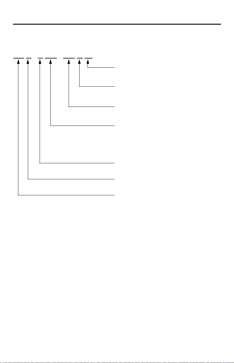
Motor Catalog Number Identification
MP G -A010 -031M 22
BRAKE
22 = No Brake
24 = 24V dcHolding Brake
FEEDBACK
M = Multi-turn High Resolution Encoder
S = Single-turn High Resolution Encoder
GEAR REDUCTION
031 = 31 to 1
091 = 91 to 1
MOTORFRAME SIZE
004 = 004 Frame
010 = 010 Frame
025 = 025 Frame
050 = 050 Frame
110 = 110 Frame
VOLTAGE RATINGOF MOTOR
A=230Vac
B=460Vac
SERIES TYPE
G = IntegratedGear
BULLETIN
Publication MP-IN003C-EN-P — April 2003
Page 4
4 MP-Series Integrated Gear Motor Installation Instructions
Before You Install the Motor
1. Remove the motor carefully from its shipping container.
2. Visually inspect the motor for any damage.
3. Examine the motor frame and mounts, drive flange, mounting holes,
and dowel pin hole for any defects.
ATTENTION
!
Do not open or attempt to open the motor.
Only a qualified Rockwell Automation employee can
service this type of motor.
Failure to observe these safety procedures could result
in personal injury or damage to equipment.
Publication MP-IN003C-EN-P — April 2003
Page 5
MP-Series Integrated Gear Motor Installation Instructions 5
Installing Your Motor
The installation must comply with all local regulations and use of
equipment and installation practices that promote electromagnetic
compatibility and safety.
All motors have a dowel pin hole for precisely aligning the motor output
on a machine. Bolt hole sizes are listed in Mounting Dimensions
beginning on page 10, and bolt torque requirements are listed in Housing
and Output Flange Connections beginning on page 22.
ATTENTION
!
ATTENTION
!
Unmounted motors, disconnected mechanical
connections, and disconnected cables are dangerous if
power is applied.
Disassembled equipment should be appropriately
identified (tagged-out) and access to electrical power
restricted (locked-out).
Before applying power to the motor, remove any
mounting bolts and screws, or other mechanical objects
which could be thrown from the motor.
Failure to observe these safety procedures could result in
personal injury.
Ensure that cables are installed and restrained to prevent
uneven tension or flexing at the cable connectors.
Excessive and uneven lateral force at the cable
connectors may result in the connector’s environmental
seal opening and closing as the cable flexes.
Failure to observe these safety procedures could result in
damage to the motor and its components.
Publication MP-IN003C-EN-P — April 2003
Page 6
6 MP-Series Integrated Gear Motor Installation Instructions
Guidelines for Installation
Observe the following guidelines when installing the motor.
ATTENTION
!
1. Allow sufficient clearances in the area of the motor for it to stay within
its specified operating temperature range 0° to 40° C (32° to 104° F).
Do not enclose the motor unless forced air is blown across the motor
for cooling. A fan blowing air across the motor will improve its
performance. Keep other heat producing devices away from the motor.
ATTENTION
!
Damage may occur to the motor bearings, gearing, and
the feedback device if sharp impact to the shaft is
applied during installation or removal of the motor.
Do not strike the MP gear motor with tools during
installation or removal.
Failure to observe these safety procedures could result in
damage to the motor and its components.
Outer surfaces of motor can reach high temperatures,
125° C (275° F), during motor operation.
Take precautions to prevent accidental contact with hot
surfaces. Consider motor surface temperature when
selecting motor mating connections and cables.
Failure to observe these safety procedures could result in
personal injury or damage to equipment.
2. Always position the motor with the connector housing pointing
downward.
Note: Gearbox input and output rotations are in identical directions.
Publication MP-IN003C-EN-P — April 2003
Page 7

MP-Series Integrated Gear Motor Installation Instructions 7
3. Properly mount and align the motor.
A. Secure the motor to the machine mounting frame. Refer to:
• Mounting Dimensions beginning on page 10 for the bolt hole
pattern of your motor.
• Housing and Output Flange Connections beginning on page 22
for the torque values for connections.
B. Move the output flange so the motor feedback device aligns at its
electronic zero position. Encoder absolute position = 0 occurs when
the dowel pin hole is aligned on the connector side of the motor
and centered on the connectors. Refer to Figure 1 on page 11 for a
visual reference of this alignment.
IMPORTANT
Proper alignment and loading of the motor are critical to
achieving reliable operation throughout the lifetime of
the motor.
When mounting the MP-Series Integrated Gear Motor,
ensure that the connections are properly aligned and
that axial and radial loads are within the specifications of
the motor.
C. Connect the output flange to the machine’s drive assembly.
Mechanical connections to the motor flange must be rigid, secure,
and properly aligned. Refer to:
• Mounting Dimensions beginning on page 10 for the bolt hole
pattern of your motor.
• Housing and Output Flange Connections beginning on page 22
for the torque values for connections.
• Motor Load Force Ratings beginning on page 23 for guidelines to
achieve 20,000 hours of motor bearing life.
4. Apply a high-temperature, medium-strength threadlock adhesive to the
mounting bolts.
Publication MP-IN003C-EN-P — April 2003
Page 8

8 MP-Series Integrated Gear Motor Installation Instructions
5. Attach all power, feedback, and brake cables after the motor is
mounted.
A. Use a drip loop in each cable to keep liquids flowing away from the
connectors.
IMPORTANT
Ensure that proper polarity is maintained when wiring a
brake connector.
The holding brake is designed to hold the motor shaft at
0 rpm and to release when power is applied - it is not
intended to stop motor rotation. Reversing the brake
polarity could cause the brake to be applied while the
motor is running. The section Holding Brake beginning
on page 27 provides information on the electrical
requirements for a brake motor.
Failure to observe proper polarity could result in damage
to the motor and its components.
B. Use Electromagnetic Compatibility (EMC) techniques to reduce
Electromagnetic Interference (EMI), commonly called noise. Noise
adversely impacts motor performance by inducing stray signals.
Effective techniques to counter EMI include filtering the AC power,
shielding and separating signal carrying lines, and practicing good
grounding techniques.
– Filter AC power by using isolated AC power transformers or properly
installed AC line filters.
– Physically separate signal lines from motor cabling and power wiring.
Do not route signal wires with motor and power wires, or over the
vent openings of servo drives.
– Ground all equipment using a single-point parallel ground system that
employs ground bus bars or large straps.
Refer to System Design for Control of Electrical Noise
(GMC-SG001x-EN-P) for information on additional electrical noise
reduction techniques.
6. If necessary, home the drive and motor system prior to use. Refer to
your drive instructions for procedures on when and how to do this.
Publication MP-IN003C-EN-P — April 2003
Page 9
MP-Series Integrated Gear Motor Installation Instructions 9
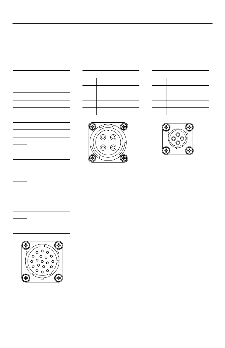
Connector Data
The tables below list the signal descriptions for the feedback, power, and
brake connector pins.
Feedback Connector Power Connector Brake Connector
High Resolution Pin Signal Pin Signal
Pin Encoder
A Sin+ B Phase V B Reserved
B Sin- C Phase W C BRC Cos+ D Ground D Reserved
DCosE Data+
F DataG Reserved
H
J
K +5V dc
LCommon
M Reserved Note: Ensure that proper
N
P
RTS+
STST Reserved
U
V
A Phase U A BR+
A
D
B
C
D
ITT Cannon
ITT Cannon
TNM 10-4
TNM 16-4
polarity is maintained
when wiring a brake
connector.
A
B
C
M
L
U
K
V
T
J
H
G
ITT Cannon
TNM 16-19
A
B
N
P
C
R
D
S
E
F
Publication MP-IN003C-EN-P — April 2003
Page 10

10 MP-Series Integrated Gear Motor Installation Instructions
Mounting Dimensions
Dimensions for MP-Series Integrated Gear Motors are provided on the
listed pages. Refer to Figure 1 on page 11 for the dimensional symbol
designations for the motors.
If your motor is one of the following, then go to: Page
MPG-A004-031x22, MPG-A004-031x24 12
MPG-A004-091x22, MPG-A004-091x24 13
MPG-x010-031x22, MPG-x010-031x24 14
MPG-x010-091x22, MPG-x010-091x24 15
MPG-x025-031x22, MPG-x025-031x24 16
MPG-x025-091x22, MPG-x025-091x24 17
MPG-x050-031x22, MPG-x050-031x24 18
MPG-x050-091x22, MPG-x050-091x24 19
MPG-x110-031x22, MPG-x110-031x24 20
MPG-x110-091x22, MPG-x110-091x24 21
Publication MP-IN003C-EN-P — April 2003
Page 11

MP-Series Integrated Gear Motor Installation Instructions 11
Figure 1
References for Motor Mounting Dimensions
L
LB
LE
AE
AF
AG
L-LB
E
T
NB
LA
D
AC
N
LD
MPG-x025-091x22 shown
P
HD
BHP (Bolt Hole Pattern)
AD
BHPA (Auxiliary
Bolt Hole Pattern)
DB
BE
Publication MP-IN003C-EN-P — April 2003
S (diameter of hole)
M (dia. of bolt circle
on motor housing)
MA (thread and depth)
MC (dia. of bolt circle
o n output flange)
MB (diameter of dowel)
Dowel pin hole aligned
at electronic zero
Page 12

12 MP-Series Integrated Gear Motor Installation Instructions
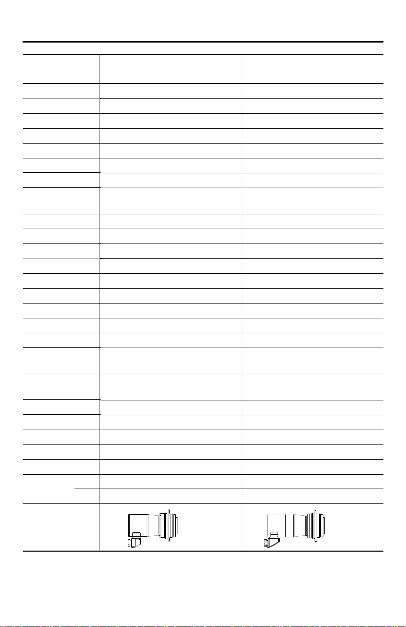
Motor Dimension
Symbol
1, 2
AC
AD
AE
AF
AG
BE
D
DB
E
HD
L
L-LB
LA
LB
LD
LE
M
MA on MC
MB
N
NB
P
S on M
T
Bolt Hole
Patterns:
BHP 45
BHPA N/A N/A
Motor Outline
MPG-A004-031x22 MPG-A004-031x24
mm (in.) mm (in.)
70 (2.76) 70 (2.76)
80 (3.15) 79.1 (3.11)
75 (2.95) 75 (2.95)
N/A N/A
N/A N/A
67.7 (2.67) 88.9 (3.50)
39.975 - 40 (1.5738) - (1.5748) 39.975 - 40 (1.5738) - (1.5748)
20 - 20.021 x 4 DP (0.7874) - (0.7882)
x (0.16) DP
20 - 20.021 x 4 DP(0.7874) - (0.7882)
x (0.16) DP
3 (0.12) 3 (0.12)
123 (4.84) 122.1 (4.81)
156.7 (5.58) 200.2 (7.88)
19.5 (0.77) 19.5 (0.77)
4 (0.16) 4 (0.16)
137.2 (5.40) 180.7 (7.11)
140.9 (5.55) 189.5 (7.46)
N/A N/A
79 (3.11) 79 (3.11)
M5 x 7
on 31.5 BC
5 - 5.012
x 6 DP
M5 x (0.28)
on (1.24) BC
(0.1967) - (0.1973)
x (0.24) DP
M5 x 7
on 31.5 BC
5 - 5.012
x 6 DP
M5 x (0.28)
on (1.24) BC
(0.1967) - (0.1973)
x (0.24) DP
63.97 - 64 (2.5185) - (2.5197) 63.97 - 64 (2.5185) - (2.5197)
63 (2.48) 63 (2.48)
86 (3.39) 86 (3.39)
4.5 on 79 BC (0.18) on (3.11) BC 4.5 on 79 BC (0.18) on (3.11) BC
7 (0.28) 7 (0.28)
o
45o
1
Motors are designed to metric dimensions (inch references are mathematical conversions).
2
Abbreviations: BC = Bolt Circle, BHP/BHPA = Bolt Hole Patterns, DP = Depth.
Publication MP-IN003C-EN-P — April 2003
Page 13

MP-Series Integrated Gear Motor Installation Instructions 13
Motor Dimension
Symbol
1, 2
AC
AD
AE
AF
AG
BE
D
DB
E
HD
L
L-LB
LA
LB
LD
LE
M
MA on MC
MB
N
NB
P
S on M
T
Bolt Hole
Patterns:
BHP 45
BHPA N/A N/A
Motor Outline
MPG-A004-091x22 MPG-A004-091x24
mm (in.) mm (in.)
70 (2.76) 70 (2.76)
80 (3.15) 79.1 (3.11)
75 (2.95) 75 (2.95)
N/A N/A
N/A N/A
67.7 (2.67) 88.9 (3.50)
39.975 - 40 (1.5738) - (1.5748) 39.975 - 40 (1.5738) - (1.5748)
20 - 20.021
x 4 DP
(0.7874) - (0.7882)
x (0.16) DP
20 - 20.021 x 4 DP (0.7874) - (0.7882)
x (0.16) DP
3 (0.12) 3 (0.12)
123 (4.84) 122.1 (4.81)
141.7 (5.58) 185.2 (7.29)
19.5 (0.77) 19.5 (0.77)
4 (0.16) 4 (0.16)
122.2 (4.81) 165.7 (6.52)
125.9 (4.96) 174.5 (6.87)
N/A N/A
79 (3.11) 79 (3.11)
M5 x 7
on 31.5 BC
5 - 5.012
x 6 DP
M5 x (0.28)
on (1.24) BC
(0.1967) - (0.1973)
x (0.24) DP
M5 x 7
on 31.5 BC
5 - 5.012
x 6 DP
M5 x (0.28)
on (1.24) BC
(0.1967) - (0.1973)
x (0.24) DP
63.97 - 64 (2.5185) - (2.5197) 63.97 - 64 (2.5185) - (2.5197)
63 (2.48) 63 (2.48)
86 (3.39) 86 (3.39)
4.5 on 79 BC (0.18) on (3.11) BC 4.5 on 79 BC (0.18) on (3.11) BC
7 (0.28) 7 (0.28)
o
45o
1
Motors are designed to metric dimensions (inch references are mathematical conversions).
2
Abbreviations: BC = Bolt Circle, BHP/BHPA = Bolt Hole Patterns, DP = Depth.
Publication MP-IN003C-EN-P — April 2003
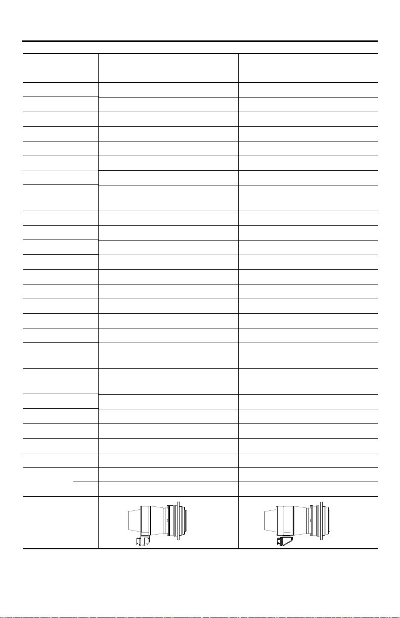
Page 14
14 MP-Series Integrated Gear Motor Installation Instructions
Motor Dimension
Symbol
1, 2
AC
AD
AE
AF
AG
BE
D
DB
E
HD
L
L-LB
LA
LB
LD
LE
M
MA on MC
MB
N
NB
P
S on M
T
Bolt Hole/
Patterns:
BHP 45
BHPA N/A N/A
Motor Outline
MPG-x010-031x22 MPG-x010-031x24
mm (in.) mm (in.)
95.00 (3.74) 95 (3.74)
82.60 (3.25) 81.7 (3.22)
83.20 (3.28) 83.20 (3.28)
N/A N/A
N/A N/A
67.70 (2.67) 88.90 (3.50)
62.97 - 63 (2.4791) - (2.4803) 62.97 - 63 (2.4791) - (2.4803)
31.5 - 31.525
x 6 DP
(1.2402) - (1.2411)
x (0.24) DP
31.5 - 31.525
x 6 DP
(1.2402) - (1.2411)
x (0.24) DP
6.00 (0.24) 6 (0.24)
141.60 (5.57) 140.70 (5.54)
184.5 (7.26) 219.50 (8.64)
30.00 (1.18) 30.00 (1.18)
7.00 (0.28) 7.00 (0.28)
154.50 (6.08) 189.50 (7.46)
156.50 (6.16) 197.10 (7.76)
N/A N/A
109.00 (4.29) 109.00 (4.29)
M6 x 10
on 50 BC
6 - 6.012
x 7 DP
M6 x (0.39)
on (1.97) BC
(0.2362) - (0.2367)
x (0.28) DP
M6 x 10
on 50 BC
6 - 6.012
x 7 DP
M6 x (0.39)
on (1.97) BC
(0.2362) - (0.2367)
x (0.28) DP
89.965 - 90 (3.5419) - (3.5433) 89.965 - 90 (3.5419) - (3.5433)
85.00 (3.35) 85.00 (3.35)
118.00 (4.65) 118.00 (4.65)
5.5 on 109 BC (0.22) on (4.29) BC 5.5 on 109 BC (0.22) on (4.29) BC
10.00 (0.39) 10.00 (0.39)
o
45o
1
Motors are designed to metric dimensions (inch references are mathematical conversions).
2
Abbreviations: BC = Bolt Circle, BHP/BHPA = Bolt Hole Patterns, DP = Depth.
Publication MP-IN003C-EN-P — April 2003
Page 15

MP-Series Integrated Gear Motor Installation Instructions 15
Motor Dimension
Symbol
1, 2
AC
AD
AE
AF
AG
BE
D
DB
E
HD
L
L-LB
LA
LB
LD
LE
M
MA on MC
MB
N
NB
P
S on M
T
Bolt Hole/
Patterns:
BHP 45
BHPA N/A N/A
Motor Outline
MPG-x010-091x22 MPG-x010-091x24
mm (in.) mm (in.)
95.00 (3.74) 95 (3.74)
82.60 (3.25) 81.7 (3.22)
83.20 (3.28) 83.20 (3.28)
N/A N/A
N/A N/A
67.70 (2.67) 88.90 (3.50)
62.97 - 63 (2.4791) - (2.4803) 62.97 - 63 (2.4791) - (2.4803)
31.5 - 31.525
x 6 DP
(1.2402) - (1.2411)
x (0.24) DP
31.5 - 31.525
x 6 DP
(1.2402) - (1.2411)
x (0.24) DP
6.00 (0.24) 6 (0.24)
141.60 (5.57) 140.70 (5.54)
169.5 (6.67) 204.5 (8.05)
30.00 (1.18) 30.00 (1.18)
7.00 (0.28) 7.00 (0.28)
139.5 (5.49) 174.5 (6.87)
141.5 (5.57) 182.1 (7.18)
N/A N/A
109.00 (4.29) 109.00 (4.29)
M6 x 10
on 50 BC
6 - 6.012
x 7 DP
M6 x (0.39)
on (1.97) BC
(0.2362) - (0.2367)
x (0.28) DP
M6 x 10
on 50 BC
6 - 6.012
x 7 DP
M6 x (0.39)
on (1.97) BC
(0.2362) - (0.2367)
x (0.28) DP
89.965 - 90 (3.5419) - (3.5433) 89.965 - 90 (3.5419) - (3.5433)
85.00 (3.35) 85.00 (3.35)
118.00 (4.65) 118.00 (4.65)
5.5 on 109 BC (0.22) on (4.29) BC 5.5 on 109 BC (0.22) on (4.29) BC
10.00 (0.39) 10.00 (0.39)
o
45o
1
Motors are designed to metric dimensions (inch references are mathematical conversions).
2
Abbreviations: BC = Bolt Circle, BHP/BHPA = Bolt Hole Patterns, DP = Depth.
Publication MP-IN003C-EN-P — April 2003
Page 16
16 MP-Series Integrated Gear Motor Installation Instructions
Motor Dimension
Symbol
1, 2
AC
AD
AE
AF
AG
BE
D
DB
E
HD
L
L-LB
LA
LB
LD
LE
M
MA on MC
MB
N
NB
P
S on M
T
Bolt Hole
Patterns:
BHP 45
BHPA 22.5
Motor Outline
MPG-x025-031x22 MPG-x025-031x24
mm (in.) mm (in.)
120 (4.72) 120 (4.72)
96.5 (3.80) 95.6 (3.76)
111.2 (4.38) 111.2 (4.38)
85 (3.35) 85 (3.35)
68.6 (2.70) 68.6 (2.70)
67.7 (2.67) 88.9 (3.50)
79.97 - 80 (3.1484) - (3.1496) 79.97 - 80 (3.1484) - (3.1496)
40 - 40.025 x
6 DP
(1.5748) - (1.5758)
x (0.24) DP
40 - 40.025 x
6 DP
(1.5748) - (1.5758)
x (0.24) DP
6.00 (0.24) 6 (0.24)
169.00 (6.65) 168.1 (6.62)
222.50 (8.76) 251.10 (9.88)
29.00 (1.14) 29.00 (1.14)
8.00 (0.31) 8.00 (0.31)
193.50 (7.62) 222.10 (8.74)
161.00 (6.34) 170.90 (6.73)
46.50 (1.83) 46.50 (1.83)
135.00 (5.31) 135.00 (5.31)
M6 x 12
on 63 BC
6 - 6.012
x 7 DP
M6 x (0.47)
on (2.48) BC
(0.2362) - (0.2367)
x (0.28) DP
M6 x 12
on 63 BC
6 - 6.012
x 7 DP
M6 x (0.47)
on (2.48) BC
(0.2362) - (0.2367)
x (0.28) DP
109.965 - 110 (4.3293) - (4.3307) 109.965 - 110 (4.3293) - (4.3307)
105.00 (4.13) 105.00 (4.13)
145.00 (5.71) 145.00 (5.71)
5.5 on 135 BC (0.22) on (5.31) BC 5.5 on 135 BC (0.22) on (5.31) BC
10.00 (0.39) 10.00 (0.39)
o
45o
o
22.5o
1
Motors are designed to metric dimensions (inch references are mathematical conversions).
2
Abbreviations: BC = Bolt Circle, BHP/BHPA = Bolt Hole Patterns, DP = Depth.
Publication MP-IN003C-EN-P — April 2003
Page 17

MP-Series Integrated Gear Motor Installation Instructions 17
Motor Dimension
Symbol
1, 2
AC
AD
AE
AF
AG
BE
D
DB
E
HD
L
L-LB
LA
LB
LD
LE
M
MA on MC
MB
N
NB
P
S on M
T
Bolt Hole
Patterns:
BHP 45
BHPA 22.5
Motor Outline
MPG-x025-091x22 MPG-x025-091x24
mm (in.) mm (in.)
120 (4.72) 120 (4.72)
96.5 (3.80) 95.6 (3.76)
111.2 (4.38) 111.3 (4.38)
85 (3.35) 85 (3.35)
68.6 (2.70) 68.6 (2.70)
67.7 (2.67) 88.9 (3.50)
79.97 - 80 (3.1484) - (3.1496) 79.97 - 80 (3.1484) - (3.1496)
40 - 40.025 x
6 DP
(1.5748) - (1.5758)
x (0.24) DP
40 - 40.025 x
6 DP
(1.5748) - (1.5758)
x (0.24) DP
6 (0.24) 6 (0.24)
169 (6.65) 168.1 (6.62)
192.5 (7.58) 221.1 (8.70)
29 (1.14) 29 (1.14)
8 (0.31) 8 (0.31)
163.50 (6.44) 192.1 (7.56)
131.00 (5.16) 140.9 (5.55)
46.50 (1.83) 46.50 (1.83)
135.00 (5.31) 135.00 (5.31)
M6 x 12
on 63 BC
6 - 6.012
x 7 DP
M6 x (0.47)
on (2.48) BC
(0.2362) - (0.2367)
x (0.28) DP
M6 x 12
on 63 BC
6 - 6.012
x 7 DP
M6 x (0.47)
on (2.48) BC
(0.2362) - (0.2367)
x (0.28) DP
109.965 - 110 (4.3293) - (4.3307) 109.965 - 110 (4.3293) - (4.3307)
105.00 (4.13) 105.00 (4.13)
145.00 (5.71) 145 (5.71)
5.5 on 135 BC (0.22) on (5.31) BC 5.5 on 135 BC (0.22) on (5.31) BC
10.00 (0.39) 10.00 (0.39)
o
45o
o
22.5o
1
Motors are designed to metric dimensions (inch references are mathematical conversions).
2
Abbreviations: BC = Bolt Circle, BHP/BHPA = Bolt Hole Pattern/Auxiliary BHP, DP = Depth.
Publication MP-IN003C-EN-P — April 2003
Page 18

18 MP-Series Integrated Gear Motor Installation Instructions
Motor Dimension
Symbol
1, 2
AC
AD
AE
AF
AG
BE
D
DB
E
HD
L
L-LB
LA
LB
LD
LE
M
MA on MC
MB
N
NB
P
S on M
T
Bolt Hole
Patterns:
BHP 30
BHPA N/A N/A
Motor Outline
MPG-x050-031x22 MPG-x050-031x24
mm (in.) mm (in.)
152 (5.98) 152 (5.98)
127 (5.00) 126.1 (4.96)
171 (6.73) 171 (6.73)
N/A 120 (4.72)
N/A 104 (4.09)
67.7 (2.67) 88.9 (3.50)
99.965 - 100 (3.9356) - (3.9370) 99.965 - 100 (3.9356) - (3.9370)
50 - 50.025
x 6 DP
(1.9685) - (1.9695)
x (0.24) DP
50 - 50.025
x 6 DP
(1.9685) - (1.9695)
x (0.24) DP
6 (0.24) 6 (0.24)
216.2 (8.51) 215.6 (8.49)
274.0 (10.79) 346 (13.63)
38 (1.50) 38 (1.50)
10 (0.39) 10 (0.39)
236 (9.29) 308 (12.13)
230.7 (9.08) 236.6 (9.31)
N/A 41 (1.61)
168.0 (6.61) 168.0 (6.61)
M8 x 15 DP on
80 BC
8.0 - 8.015
x 7 DP
(M8 x (0.59) DP on
(3.15) BC
(0.3150) - (0.3156)
x (0.28) DP
M8 x 15 DP on
80 BC
8.0 - 8.015
x 7 DP
(M8 x (0.59) DP on
(3.15) BC
(0.3150) - (0.3156)
x (0.28) DP
139.96 - 140 (5.5102) - (5.5118) 139.96 - 140 (5.5102) - (5.5118)
136 (5.35) 136 (5.35)
179 (7.05) 179 (7.05)
6.6 on 168 BC (0.26) on (6.61) BC 6.6 on 168 BC (0.26) on (6.61) BC
14.6 (0.57) 14.6 (0.57)
o
30o
1
Motors are designed to metric dimensions (inch references are mathematical conversions).
2
Abbreviations: BC = Bolt Circle, BHP/BHPA = Bolt Hole Patterns, DP = Depth.
Publication MP-IN003C-EN-P — April 2003
Page 19

MP-Series Integrated Gear Motor Installation Instructions 19
Motor Dimension
Symbol
1, 2
AC
AD
AE
AF
AG
BE
D
DB
E
HD
L
L-LB
LA
LB
LD
LE
M
MA on MC
MB
N
NB
P
S on M
T
Bolt Hole
Patterns:
BHP 30
BHPA N/A N/A
Motor Outline
MPG-x050-091x22 MPG-x050-091x24
mm (in.) mm (in.)
152 (5.98) 152 (5.98)
116.5 (4.59) 115.6 (4.55)
150.5 (5.93) 151 (5.94)
86 (3.39) 86 (3.39)
72 (2.83) 72 (2.83)
67.7 (2.67) 88.9 (3.50)
99.965 - 100 (3.9356) - (3.9370) 99.965 - 100 (3.9356) - (3.9370)
50 - 50.025
x 6 DP
(1.9685) - (1.9695)
x (0.24) DP
50 - 50.025
x 6 DP
(1.9685) - (1.9695)
x (0.24) DP
6 (0.24) 6 (0.24)
206 (8.11) 205.1 (8.07)
227 (8.94) 256.5 (10.10)
38 (1.50) 38 (1.50)
10 (0.39) 10 (0.39)
189 (7.44) 218.5 (8.60)
156 (6.14) 161.9 (6.37)
42 (1.65) 42 (1.65)
168.0 (6.61) 168.0 (6.61)
M8 x 15 DP on
80 BC
8.0 - 8.015
x 7 DP
M8 x (0.59) DP on
(3.15) BC
(0.3150) - (0.3156)
x (0.28) DP
M8 x 15 DP on
80 BC
8.0 - 8.015
x 7 DP
M8 x (0.59) DP on
(3.15) BC
(0.3150) - (0.3156)
x (0.28) DP
139.96 - 140 (5.5102) - (5.5118) 139.96 - 140 (5.5102) - (5.5118)
136 (5.35) 136 (5.35)
179 (7.05) 179 (7.05)
6.6 on 168 BC (0.26) on (6.61) BC 6.6 on 168 BC (0.26) on (6.61) BC
14.6 (0.57) 14.6 (0.57)
o
30o
1
Motors are designed to metric dimensions (inch references are mathematical conversions).
2
Abbreviations: BC = Bolt Circle, BHP/BHPA = Bolt Hole Patterns, DP = Depth.
Publication MP-IN003C-EN-P — April 2003
Page 20

20 MP-Series Integrated Gear Motor Installation Instructions
Motor Dimension
Symbol
1, 2
AC
AD
AE
AF
AG
BE
D
DB
E
HD
L
L-LB
LA
LB
LD
LE
M
MA on MC
MB
N
NB
P
S on M
T
Bolt Hole
Patterns:
BHP 30
BHPA N/A N/A
Motor Outline
MPG-x110-031x22 MPG-x110-031x24
mm (in.) mm (in.)
212 (8.35) 212 (8.35)
127 (5.0) 126.1 (4.96)
171 (6.73) 171 (6.73)
N/A 120 (4.72)
N/A 106 (4.17)
67.7 (2.67) 88.9 (3.50)
159.96 - 160 (6.2976) - (6.2992) 159.96 - 160 (6.2976) - (6.2992)
80 - 80.03
x 8 DP
(3.1496) - (3.1508)
x (0.31) DP
80 - 80.03
x 8 DP
(3.1496) - (3.1508)
x (0.31) DP
8 (0.31) 8 (0.31)
250.5 (9.86) 249.6 (9.83)
300.0 (11.81) 372 (14.65)
50 (1.97) 50 (1.97)
12 (0.47) 12 (0.47)
250 (9.84) 322 (12.68)
244.7 (9.63) 250.6 (9.87)
N/A 41 (1.61)
233 (9.17) 233 (9.17)
M10 x 20 on
125 BC
10 - 10.015
x 10 DP
(M10 x (0.79) on
(4.92) BC
(0.3937) - (0.3943)
x (0.39) DP
M10 x 20 on
125 BC
10 - 10.015
x 10 DP
(M10 x (0.79) on
(4.92) BC
(0.3937) - (0.3943)
x (0.39) DP
199.954 - 200 (7.8722) - (7.8740) 199.954 - 200 (7.8722) - (7.8740)
196 (7.72) 196 (7.72)
247 (9.72) 247 (9.72)
9 on 233 BC (0.35) on (9.17) BC 9 on 233 BC (0.35) on (9.17) BC
15 (0.59) 15 (0.59)
o
30o
1
Motors are designed to metric dimensions (inch references are mathematical conversions).
2
Abbreviations: BC = Bolt Circle, BHP/BHPA = Bolt Hole Patterns, DP = Depth.
Publication MP-IN003C-EN-P — April 2003
Page 21

MP-Series Integrated Gear Motor Installation Instructions 21
Motor Dimension
Symbol
1, 2
AC
AD
AE
AF
AG
BE
D
DB
E
HD
L
L-LB
LA
LB
LD
LE
M
MA on MC
MB
N
NB
P
S on M
T
Bolt Hole
Patterns:
BHP 30
BHPA N/A N/A
Motor Outline
MPG-x110-091x22 MPG-x110-091x24
mm (in.) mm (in.)
212 (8.35) 212 (8.35)
127 (5.0) 126.1 (4.96)
171 (6.73) 171 (6.73)
N/A 120 (4.72)
N/A 106 (4.17)
67.7 (2.67) 88.9 (3.50)
159.96 - 160 (6.2976) - (6.2992) 159.96 - 160 (6.2976) - (6.2992)
80 - 80.03 x
8 DP
(3.1496) - (3.1508)
x (0.31) DP
80 - 80.03 x
8 DP
(3.1496) - (3.1508)
x (0.31) DP
8 (0.31) 8 (0.31)
250.5 (9.86) 249.6 (9.83)
285 (11.22) 357 (14.06)
50 (1.97) 50 (1.97)
12 (0.47) 12 (0.47)
235 (9.35) 307 (12.09)
229.7 (9.04) 235.6 (9.28)
N/A 41 (1.61)
233 (9.17) 233 (9.17)
M10 x 20 on
125 BC
10 - 10.015
x 10 DP
(M10 x (0.79) on
(4.92) BC
(0.3937) - (0.3943)
x (0.39) DP
M10 x 20 on
125 BC
10 - 10.015
x 10 DP
(M10 x (0.79) on
(4.92) BC
(0.3937) - (0.3943)
x (0.39) DP
199.954 - 200 (7.8722) - (7.8740) 199.954 - 200 (7.8722) - (7.8740)
196 (7.72) 196 (7.72)
247 (9.72) 247 (9.72)
9 on 233 BC (0.35) on (9.17) BC 9 on 233 BC (0.35) on (9.17) BC
15 (0.59) 15 (0.59)
o
30o
1
Motors are designed to metric dimensions (inch references are mathematical conversions).
2
Abbreviations: BC = Bolt Circle, BHP/BHPA = Bolt Hole Patterns, DP = Depth.
Publication MP-IN003C-EN-P — April 2003
Page 22

22 MP-Series Integrated Gear Motor Installation Instructions
Housing and Output Flange Connections
The following table provides ISO 898-1 mounting bolt strength class
requirements for the motor housing, and tightening torques for
connecting the motor housing and the ISO 9409 compliant output flange
to your assembly. Apply a high-temperature, medium-strength threadlock
adhesive to the mounting bolts.
IMPORTANT
A loose or slipping connection will cause system
instability and may damage the MP gear motor.
All connections between the assembly and the MP gear
motor must be rigid to achieve acceptable response from
both the motor and the system.
Periodically inspect connections to verify their rigidity.
Motor Bolt Strength
Grade
ISO 898-1
MPG-A004 10.9 4.1 (36.3) 8.1 (72)
MPG-A010, MPG-B010 10.9 8.1 (72) 14.0 (124)
MPG-A025, MPG-B025 10.9 8.1 (72) 14.0 (124)
MPG-A050, MPG-B050 10.9 14.0 (124) 34.0 (301)
MPG-A110, MPG-B110 10.9 34.0 (301) 67.0 (593)
1
Refer to Mounting Dimensions beginning on page 10 for hole dimensions.
Tor qu e
Motor Housing
Nm (lb-in.) Nm (lb-in.)
1
Output Flange
1
Publication MP-IN003C-EN-P — April 2003
Page 23

MP-Series Integrated Gear Motor Installation Instructions 23
Motor Load Force Ratings
Motors are capable of operating with a sustained shaft load. The radial
and axial load force location is shown in the figure, and maximum values
for motors are in the following tables.
Figure 2
Load Forces on Shaft
Radial load force applied at mounting end of output flange
Axial load force applied at shaft centerline
The following tables represent 20,000 hour L10 bearing fatigue life at
various loads and speeds. This 20,000 hour life does not account for
possible application-specific life reduction that may occur due to bearing
grease contamination from external sources, improper alignment, or
excessive loading.
Publication MP-IN003C-EN-P — April 2003
Page 24

24 MP-Series Integrated Gear Motor Installation Instructions
Radial Load Force Ratings
Motor 40 rpm 60 rpm 100 rpm 156 rpm 194 rpm
kg (lb) kg (lb) kg (lb) kg (lb) kg (lb)
MPG-A004-031 179 (393) —— 162 (356) 139 (307) 130 (286)
1
MPG-A004-091
MPG-A010-031
MPG-A010-091
MPG-A025-031
MPG-A025-091
MPG-A050-031
MPG-A050-091
MPG-A110-031
MPG-A110-091
MPG-B010-031
MPG-B010-091
MPG-B025-031
MPG-B025-091
MPG-B050-031
MPG-B050-091
MPG-B110-031
MPG-B110-091
1
Measurement speeds: 40, 66 rpm.
2
Measurement speeds: 40, 100, 157 rpm.
3
Measurement speeds: 40, 65 rpm.
4
Measurement speeds: 40, 100, 158 rpm.
5
Measurement speeds: 40, 62 rpm.
6
Measurement speeds: 20, 50, 81 rpm.
7
Measurement speeds: 20, 41 rpm.
8
Measurement speeds: 20, 50, 93 rpm.
9
Measurement speeds: 20, 38 rpm.
179 (393) 179 (393) —— —— ——
2
337 (743) —— 286 (631) 246 (543) ——
3
337 (743) 330 (728) —— —— ——
4
478 (1053) —— 406 (895) 342 (753) ——
5
478 (1053) 476 (1050) —— —— ——
6
1724 (3801) 1509 (3325) 1305 (2877) —— ——
7
1724 (3801) 1602 (3530) —— —— ——
8
3144 (6930) 2751 (6062) 2283 (5032) —— ——
9
3144 (6930) 2987 (6583) —— —— ——
10
337 (743) —— 286 (631) 246 (543) 224 (494)
11
337 (743) 321 (707) —— —— ——
12
478 (1053) —— 406 (895) 350 (772) ——
13
478 (1053) 469 (1033) —— —— ——
14
1724 (3801) 1509 (3325) 1305 (2877) —— ——
15
1724 (3801) 1509 (3325) —— —— ——
16
3144 (6930) 2751 (6062) 2407 (5305) —— ——
17
3144 (6930) 2987 (6583) —— —— ——
10
Measurement speeds: 40, 100, 157, 208 rpm.
11
Measurement speeds: 40, 71 rpm.
12
Measurement speeds: 40, 100, 156 rpm.
13
Measurement speeds: 40, 65 rpm.
14
Measurement speeds: 20, 50, 81 rpm.
15
Measurement speeds: 20, 50 rpm.
16
Measurement speeds: 20, 50, 78 rpm.
17
Measurement speeds: 20, 38 rpm.
Publication MP-IN003C-EN-P — April 2003
Page 25

MP-Series Integrated Gear Motor Installation Instructions 25
Axial Load Force Ratings (Maximum Radial Load)
Motor 40 rpm 60 rpm 100 rpm 156 rpm 194 rpm
kg (lb) kg (lb) kg (lb) kg (lb) kg (lb)
MPG-A004-031 166 (366) 102 (225) —— 88 (194) 82 (180)
1
MPG-A004-091
MPG-A010-031
MPG-A010-091
MPG-A025-031
MPG-A025-091
MPG-A050-031
MPG-A050-091
MPG-A110-031
MPG-A110-091
MPG-B010-031
MPG-B010-091
MPG-B025-031
MPG-B025-091
MPG-B050-031
MPG-B050-091
MPG-B110-031
MPG-B110-091
1
Measurement speeds: 40, 66 rpm.
2
Measurement speeds: 40, 100, 157 rpm.
3
Measurement speeds: 40, 65 rpm.
4
Measurement speeds: 40, 100, 158 rpm.
5
Measurement speeds: 40, 62 rpm.
6
Measurement speeds: 20, 50, 81 rpm.
7
Measurement speeds: 20, 41 rpm.
8
Measurement speeds: 20, 50, 93 rpm.
9
Measurement speeds: 20, 38 rpm.
166 (366) 123 (272) —— —— ——
2
219 (483) —— 201 (443) 173 (381) ——
3
219 (483) 219 (483) —— —— ——
4
407 (897) —— 254 (559) 213 (471) ——
5
407 (897) 298 (656) —— —— ——
6
625 (1378) 456 (1004) 394 (868) —— ——
7
625 (1378) 483 (1066) —— —— ——
8
1025 (2259) 862 (1899) 715 (1577) —— ——
9
1025 (2259) 936 (2063) —— —— ——
10
219 (483) —— 201 (443) 173 (381) 157 (347)
11
219 (483) 219 (483) —— —— ——
12
407 (897) —— 254 (559) 219 (482) ——
13
407 (897) 293 (645) —— —— ——
14
625 (1378) 456 (1004) 394 (868) —— ——
15
625 (1378) 456 (1004) —— —— ——
16
1025 (2259) 862 (1899) 754 (1662) —— ——
17
1025 (2259) 936 (2063) —— —— ——
10
Measurement speeds: 40, 100, 157, 208 rpm.
11
Measurement speeds: 40, 71 rpm.
12
Measurement speeds: 40, 100, 156 rpm.
13
Measurement speeds: 40, 65 rpm.
14
Measurement speeds: 20, 50, 81 rpm.
15
Measurement speeds: 20, 50 rpm.
16
Measurement speeds: 20, 50, 78 rpm.
17
Measurement speeds: 20, 38 rpm.
Publication MP-IN003C-EN-P — April 2003
Page 26

26 MP-Series Integrated Gear Motor Installation Instructions
Axial Load Force Ratings (Zero Radial Load)
Motor Full rpm range
kg (lb)
MPG-A004-031 1 166 (366)
2
MPG-A004-091
MPG-A010-031
MPG-A010-091
MPG-A025-031
MPG-A025-091
MPG-A050-031
MPG-A050-091
MPG-A110-031
MPG-A110-091
MPG-B010-031
MPG-B010-091
MPG-B025-031
MPG-B025-091
MPG-B050-031
MPG-B050-091
MPG-B110-031
MPG-B110-091
1
Measurement speeds: 40, 100, 156, 194 rpm.
2
Measurement speeds: 40, 66 rpm.
3
Measurement speeds: 40, 100, 157 rpm.
4
Measurement speeds: 40, 65 rpm.
5
Measurement speeds: 40, 100, 158 rpm.
6
Measurement speeds: 40, 62 rpm.
7
Measurement speeds: 20, 50, 81 rpm.
8
Measurement speeds: 20, 41 rpm.
9
Measurement speeds: 20, 50, 93 rpm.
10
Measurement speeds: 20, 38 rpm.
11
Measurement speeds: 40, 100, 157, 208 rpm.
12
Measurement speeds: 40, 71 rpm.
13
Measurement speeds: 40, 100, 156 rpm.
14
Measurement speeds: 40, 65 rpm.
15
Measurement speeds: 20, 50, 81 rpm.
16
Measurement speeds: 20, 50 rpm.
17
Measurement speeds: 20, 50, 78 rpm.
18
Measurement speeds: 20, 38 rpm.
166 (366)
3
219 (483)
4
219 (483)
5
423 (933)
6
423 (933)
7
625 (1378)
8
625 (1378)
9
1025 (2259)
10
1025 (2259)
11
219 (483)
12
219 (483)
13
423 (933)
14
423 (933)
15
625 (1378)
16
625 (1378)
17
1025 (2259)
18
1025 (2259)
Publication MP-IN003C-EN-P — April 2003
Page 27

MP-Series Integrated Gear Motor Installation Instructions 27
Holding Brake
A 24V dc holding brake is an option on the MP-Series Integrated Gear
Motor. The following tables provide specifications on the brake.
IMPORTANT
Ensure that proper polarity is maintained when wiring a
brake connector.
Description Gear
Ratio
Type Permanent Magnet
Holding Torque -031 25 Nm (221 lb-in.) 68 Nm (602 lb-in.) 68 Nm (602 lb-in.)
-091 32 Nm (283 lb-in.) 80 Nm (708 lb-in.) 205 Nm (
Backlash None with brake engaged
Voltage Input 21.6 to 25.4V dc
Current Input 24V dc,
o
to 30o C (68o to 86o F)
20
Coil Resistance at 20
Coil Resistance at 40
at maximum continuous stall torque
Release Time Delay
(when voltage is applied)
Engage Time
(when voltage is removed)
o
C (68o F) 67 to 77 Ohms 48.7 to 56 Ohms 48.7 to 56 Ohms
o
C (104o F), operating
Description Gear
Ratio
Type Permanent Magnet
Holding Torque -031 193 Nm (1711 lb-in.) 693 Nm (6137 lb-in.)
-091 500 Nm (4425 lb-in.) 1300 Nm (11506 lb-in.)
Backlash None with brake engaged
Voltage Input 21.6 to 25.4V dc
Current Input 24V dc,
o
to 30o C (68o to 86o F)
20
Coil Resistance at 20
Coil Resistance at 40
at maximum continuous stall torque
Release Time Delay
(when voltage is applied)
Engage Time
(when voltage is removed)
o
C (68o F) 44.7 to 51.3 Ohms 22.4 to 25.6 Ohms
o
C (104o F), operating
MPG-A004-xxx MPG-A010-xxx,
MPG-B010-xxx
~0.33 A ~0.45 A ~0.45 A
72 to 83 Ohms 52 to 61 Ohms 48 to 55 Ohms
22 ms 25 ms 25 ms
7 ms 6 ms 6 ms
MPG-A050-xxx,
MPG-B050-xxx
~0.5 A ~1.0 A
48 to 55 Ohms 24 to 28 Ohms
35 ms 35 ms
7 ms 7 ms
MPG-A110-xxx,
MPG-B110-xxx
MPG-A025-xxx,
MPG-B025-xxx
1819
lb-in.)
Publication MP-IN003C-EN-P — April 2003
Page 28

28 MP-Series Integrated Gear Motor Installation Instructions
Cables and Connector Kits
Factory manufactured feedback and power cables are available in
standard cable lengths. They provide environmental sealing and proper
shield termination to an IP66 rating, which exceeds the MP gear motor’s
IP64 rating. For a complete listing of available cables refer to your drive’s
installation manual, contact your nearest Rockwell Automation sales
office, or access the information from the web sites referenced in Related
Documentation on page 30.
Building and Installing Cables
Knowledgeable cable routing and careful cable construction improves
system electromagnetic compatibility (EMC).
To build and install cables, perform the following steps:
1. Keep wire lengths as short as physically possible.
2. Route signal cables (encoder, serial, analog, and brake) away from
motor and power wiring.
3. Separate cables by 0.3 m (1 ft) minimum for every 9 m (30 ft) of
parallel run.
4. Ground both ends of the encoder cable shield and twist the signal wire
pairs to prevent electromagnetic interference (EMI) from other
equipment.
ATTENTION
!
Publication MP-IN003C-EN-P — April 2003
High voltage can be present on the shield of a power
cable, if the shield is not grounded.
Ensure there is a connection to ground for any power
cable shield.
Failure to observe these safety procedures could result in
personal injury or damage to equipment.
Page 29

MP-Series Integrated Gear Motor Installation Instructions 29
If you choose to build your own cables, the following connector kits are
available for MP-Series Integrated Gear Motors. These solder-type
connectors mate with the motor-mounted connectors and provide
environmental sealing with shield termination.
Each connector kit includes the requisite number and size of solder-type
contact pins, a connector housing, and a connector backshell. As an
example, finished and exploded views of the connector kit are shown
below.
Catalog Number Connector
Ty pe
Accepts
Wire Gauge
2
mm
1
(AWG)
Accepts
Cable Diameter Gauge
mm2 (in.)
2090-MPPC-S Power - Straight 2.5-4.0 (14-12) 7.9-12.4 (0.31-0.49)
2090-MPFC-S Feedback - Straight 0.08-2.5 (28-14)
2090-MPBC-S Brake - Straight 4.3-7.4 (0.17-0.29)
1
Refer to your drive’s installation manual for recommended wire gauges.
EndbellConnector Coupling Ring
Connector Housing
O-Ring
InstallO-Ring
on groove in
Connector Housing
Bushing
Ring Cone
Snap Ring Cone
onto Bushing
Sealing Grommet
Cable Clamp Ring
Clamp Nut
Gear Lubricant
Gear units are permanently lubricated at the factory.
Publication MP-IN003C-EN-P — April 2003
Page 30

MP-Series Integrated Gear Motor Installation Instructions 30
Related Documentation
The following documents contain additional information concerning
related Allen-Bradley products. To obtain a copy, contact your local
Rockwell Automation office or distributor, or access on-line at:
www.theautomationbookstore.com
For information about: Read this document: Publication Number
Small Frame (<
Large Frame (>
Connecting to an Ultra5000™ drive Ultra5000 Intelligent
Connecting to an Ultra3000™ drive Ultra3000 Digital Servo
Connecting to an Kinetix™ 6000 drive Kinetix 6000 Multi-Axis
A glossary of industrial automation
terms and abbreviations
How to minimize and control
system-level noise
An overview of Allen-Bradley motion
controls and systems, including
information about MP-Series motors.
165 mm) MP Motors
215 mm) MP Motors
or
www.ab.com/manuals/gmc
MP-Series Brushless Servo
Motor Manuals
Positioning Drives
Installation Manual
Drives Installation Manual
Servo Drive Installation
Manual
Allen-Bradley Industrial
Automation Glossary
System Design for Control of
Electrical Noise
Motion Control Selection
Guide
.
MP-IN001x-EN-P
MP-IN002x-EN-P
2098-IN001x-EN-P
2098-IN003x-EN-P
2094-IN001x-EN-P
AG-7.1
GMC-RM001x-EN-P
GMC-SG001x-EN-P
Publication MP-IN003C-EN-P — April 2003
Page 31

Notes
MP-Series Integrated Gear Motor Installation Instructions 31
Publication MP-IN003C-EN-P — April 2003
Page 32

For more information refer to our web site:
For Allen-Bradley Technical Support information refer to:
Allen-Bradley is a registered trademark of Rockwell Automation, Inc.
Kinetix, Ultra3000 and Ultra5000 are trademarks of Rockwell Automation, Inc.
www.ab.com/ motion
www.ab.com/support
or Tel: (1) 440.646.5800
Publication MP-IN003C-EN-P — April 2003 PN 0013-2052-003-01
Supersedes Publication MPG-IN003B-EN-P April 2 002 Copyright © 2003 Rockwell Automation, Inc. All rights reserved. Print ed in the USA.
 Loading...