

Page 1

Installation Instructions
MATGUARD PRESSURE SENSITIVE SAFETY MAT SYSTEM
CONTROL UNIT
Supply Voltage 230/110VAC (see selector) 50-60Hz or 24VAC/DC
IP65 Hoseproof, Dust tight
Safety Contacts 250V 2A N/O Aux Contacts 250V 2A N/C
MatGuard Mat Voltage 24VDC
EN ISO 13849-1 Category 3, System Response Time 35ms
See user manual for further information
MANUAL
RESET MODE
MACHINE
ENABLED
POWER
AUTO
RESET MODE
PRESS
TO RESET
ISOLATE ALL POWER
SUPPLIES BEFORE OPENING
MADE IN THE UK
83HA TYPE 1 A300
IND CONT EQ
MatGuard
Type No:
440F-C4000P
R
A1• 1 2 MC Y1 Y3 Y5 +
RESET IND
•
13 23 31
•
A2
RESET IND
3 4 MC Y2 Y4 Y6 • 14 24 32
•
110/230VAC selectable
EN 13856-1, EN ISO 13849-1 Cat 3
24V AC/DC
440F-C4000D
Response time: 35mS
MADE IN ENGLAND
POWER
AUTO RESET MODE
MANUAL RESET MODE
MACHINE ENABLED
R
83HA A300
IND CONT EQ
MatGuard
Isolate
before
opening
MATGUARD PRESSURE SENSITIVE SAFETY MAT SYSTEM
CONTROL UNIT
Supply Voltage 230/110VAC (see selector) 50-60Hz or 24VAC/DC
IP65 Hoseproof, Dust tight
Safety Contacts 250V 2A N/O Aux Contacts 250V 2A N/C
MatGuard Mat Voltage 24VDC
EN ISO 13849-1 Category 3, System Response Time 35ms
See user manual for further information
AUTO
RESET MODE
MACHINE
ENABLED
POWER
MANUAL
RESET MODE
PRESS TO RESET
1234567 8
MAT STATUS
ISOLATE ALL POWER
SUPPLIES BEFORE OPENING
MADE IN THE UK.
MatGuard
Type No:
440F-C28013
R
Original Instructions
MatGuard Pressure Sensitive Safety Mat System
Catalog Numbers 440F-C4000D, 440F-C4000P, 440F-C4000S, 440F-C28013
Top ic Pa g e
Summary of Changes 1
Introduction 1
Specifications 2
System Description 3
Applications 5
System Configuration 6
Safety Mat Positioning 7
Electric Interfacing 9
Final Safety Mat Layout 12
Wiring 12
Final Details 12
Installation 13
Commissioning 18
Maintenance 18
Repair 19
Replacement Parts 20
Service 21
Approximate Dimensions 21
Declaration of Conformity 22
Figure 1 - Control Unit Marking 440F-C4000P and 440F-C4000S
Figure 2 - Control Unit Marking 440F-C4000D
Figure 3 - Safety Mat Marking
(a)
Summary of Changes
This publication contains the following new or updated information. This list
includes substantive updates only and is not intended to reflect all changes.
Top ic Pa ge
Updated Figure 1
Updated Conformity 2
Updated Safety mat conformity 2
Added Declaration of Conformity 22
Introduction
The MatGuard™ Pressure Sensitive Safety Mat System is designed for use as a
safety product in an industrial environment by professional personnel. The system
protects against risks that the isolation of electrical power when an operator is in
the vicinity of the hazard can minimize. This instruction covers the installation and
use of all parts of the system, including special shapes and sizes of safety mats.
Only suitably trained and qualified personnel must perform all installation
procedures in accordance with statutory requirements for safety. Read this
instruction in full before installation. After installation, retain this instruction in a
safe and accessible place. For further assistance, contact your local Allen-Bradley
product distributor or Rockwell Automation sales office.
…Figure 4 1
R
MatGuard
SENSOR MAT
MADE IN U.S.A.
REFER TO USER MANUAL
4 M 20 IND CONT EQ
Model No.
EN 13856-1
Figure 4 - Mat Manager Markings 440F-C28013
(a) The position of the Reset button differs on 440F-C4000 control units.
Page 2

MatGuard Pressure Sensitive Safety Mat System Installation Instructions
Specifications
Table 1 - Control Units and Mat Manager
Attribute 440F-C4000D 440F-C4000P 440F-C4000S 440F-C28013
Conformity EN 13856-1, EN 62061, Category 3, UL 508
Response time
Environmental protection
Impulse withstand voltage 2500V
Contamination level III
Switched current/voltage, min 10 mA/10V
Power supply (user select)
Power consumption < 9VA 6 W
Relay outputs
Utilization category
Outputs Remote reset/status indicator: 24V DC/0.24 W
Inputs Remote reset switch (2 x N.O.)
Safety inputs 4-wire mat 8 x 4-wire mats with molded Allen-Bradley® connectors
Status Indicator
Internal controls AC Voltage selector, auto/manual reset selector
Internal supply fuses
Operating temperature range -10…+45 °C (14…113 °F)
Relative humidity Up to 90% at 50 °C (122 °F)
Vibration
MC-MC contactor monitor loop N.C. contactor loop
Conductor size, max
Ter min als
Installation group C in accordance with VDE 0110
Material Polycarbonate Steel c/w polycarbonate screen
Mounting details 35 mm (1.38 in.) DIN rail 4 x M4 holes 4 x M6 holes
Miscellaneous
Housing (D x H x W)
Weight 0.92 kg (2.03 lb) 0.88 kg (1.94 lb) 0.3.2 kg (7.05 lb)
(1) Safety mat pressed, safety contacts open.
(2) 110V setting allows for use at 100V ±10%.
(1)
35 ms
• Enclosure-IP40: DIN0470
• Terminals-IP20: DIN0470
(2)
110/230V AC
• 2 x independent volt free N.O. safety contacts
• 1 x volt free N.C. auxiliary contact
• NB - Aux must not be used for safety circuit
• Fuse externally, 5 A max (quick acting) for AC/2.5 A max (quick acting) for DC
•AC - 15; 4 A/250V AC
•DC - 13; 2 A/30V DC
• 1 - Power (green)
• 2 - Auto Reset mode (green)
•3 - Manual Reset mode (green)
• 4 - Machine-enabled (green)
• 500 mA replaceable (1 off)
• 500 mA resettable (1 off)
Tested in accordance with IEC 68-2-6, frequency range
10...55 Hz, displacement 0.15 mm (0.01 in.)
10 cycles per axis, sweep rate, 1 octave per minute
2 x 1.5 mm
stripped 8 mm (0.31 in.), 2 x 2.5 mm
(14 AWG) solid conductor
Plus/minus captive terminal screws M3.5
with self-lifting connection, washer
terminal boards separately removable
Manual Reset mode (M) requires a
connected Reset button
120 mm x 73 mm x 152 mm
(4.72 in. x 2.87 in. x 5.98 in.), 32 way DIN rail
(50-60Hz) and 24V AC/DC +10% -15%
2
(16 AWG) stranded with sleeves
IP65 NEMA12
500 mA replaceable (2 off)
2
2
(16 AWG) stranded with sleeves stripped 5 mm (0.2 in.), 1 x 2.5 mm2 (14 AWG) solid conductor
1 x 1.5 mm
Minus terminal screws M2.5 that are mounted at 45° to PCB
—
75 mm x 180 mm x 130 mm
(2.95 in. x 7.09 in. x 5.12 in.)
143 mm x 230 mm x 210 mm
(5.63 in. x 9.06 in. x 8.27 in.)
24V AC/DC or 110/230V selectable
• 2 x independent volt free N.O. safety contacts
• 1 x independent volt free N.C. monitored contact
• 1 x volt free N.C. auxiliary contact
• 1 x volt free N.O. auxiliary contact
•1 - Power (green)
• 2 - Manual Reset mode (green)
• 3 - Auto Reset mode (green)
• 4 - Machine-enabled (green)
• 5…12 - Channel fault status (green/red)
Table 2 - Safety Mat
Attribute Value
Safety mat conformity EN 13856-1, EN ISO 13849-1, Category 1, UL 508
Weight of person with detection, min 35 kg (77 lb)
Detection zone, max
Number of individual safety mats, max
Total length of connection wires, max 200 m (656 ft)
2
(sensor mats)
Mass / m
Environmental protection mats IP67
Mechanical life
Relative humidity 0…100%
Safety mat outer cover material Vinyl
Standard color Yellow
Operating temperature range -10…+55 °C (14…131 °F)
Storage temperature range -40…+70 °C (-40…+158 °F)
2
100 m
(1076 ft2)
No limit (up to max 100 m
24 kg (53 lb)
6
1 x 10
operations
2
)
The system that is composed of interconnected safety mats and
control unit meets the requirements of EN ISO 13849-1 Category 3.
2 Rockwell Automation Publication MATGRD-IN001C-EN-P - January 2024
Page 3

MatGuard Pressure Sensitive Safety Mat System Installation Instructions
Molded
Vinyl
Steel
Plates
System Description
The safety mat system comprises one or more interconnected pressure sensitive
safety mats and a control unit. There are no dead zones within the detection zone.
Individual safety mat sections are available in rectangular standard sizes and also
in specially cut shapes, up to the size of the largest standard safety mat. All safety
mats have the same construction and operation principle.
Each safety mat has two conductive plates that are held apart by non-conductive
compressible separators. The safety mats operate at 24V DC and connect in series
to form a floor level sensing system for hazardous areas around the machinery.
The control unit monitors the circuit through the safety mats. When the area is
clear, the control unit provides a signal to the machine control circuit. When you
step on any safety mat, the conductive plates touch and the resistance in the
circuit drops, which causes the control unit to shut down the machine. Any single
electrical fault in the safety mat, wiring, or control unit is detected and the control
unit outputs go to a safe (off) state. The molded vinyl safety mats are sealed to
IP67.
440F-C28013 Mat Manager
The unit comprises an eight-channel safety mat system. When you step on any
safety mat, the control unit shuts down the machine and the channel fault status
display indicates which safety mat is operated.
Two operating modes are available: Manual Reset and Auto Reset.
In Manual Reset mode, the output-on signal can only be restored after the removal
of the actuating force and after a reset. To reset the unit manually, push and
release the lid-mounted control unit Reset button or a remote-mounted button. At
power-on or following the loss and subsequent restoration of power, the outputs
are off until a reset signal is received, even if the safety mat is not actuated.
In Auto Reset mode, the output-on signal is achieved solely by the removal of the
actuating force. For both modes, the safety contacts are always off (open) after
the safety mat actuates. See Installation on page 13 for mode selection. Individual
safety mats connect to each other and to the control unit via four wires. The
control unit has cross-monitored safety relays and it is possible to configure the
unit so that an external contactor fault is detectable.
The control unit complies with the requirements of EN ISO 13849-1 Category 3
regarding electrical faults and can be met for the associated part of the machine
control system. Compliance with the requirements of EN ISO 13849-1 Category 1 is
achieved for the safety mat sensors. Installation on page 13 details the interfacing.
The operating principle of the safety mat is shown in Figure 5 and Figure 6.
Figure 5 - Safety Mat at Reset
Figure 6 - Safety Mat Activated
When the safety mat activates, the non-conductive compressible separators
(shown as black) compress into their recess, which allows the two plates to make
contact, and offers all-over sensitivity. The system is intended for the detection of
adult persons with a weight of 35 kg (77.16 lb) or more. The system is suitable for
the detection of adults who use walking aids (walking sticks or frames).
IMPORTANT The system is not suitable for the detection of children. The
The vinyl outer surface of the safety mat is sealed to resist the ingress of liquids.
The seal resists bleaches, acids, salt, and most industrial chemicals. See Table 3
on page 6 for detailed guidance on chemical resistance.
The system operates at 24V DC with restricted fault current. Therefore, damage to
the safety mats or interconnecting wiring does not generate any electric shock
hazard in normal circumstances.
system must not be used with any additional covering on
the safety mat.
Rockwell Automation Publication MATGRD-IN001C-EN-P - January 2024 3
Page 4
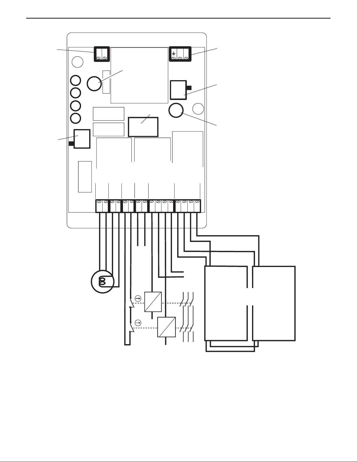
MatGuard Pressure Sensitive Safety Mat System Installation Instructions
341223 2413 1431 32MC
MCN/O PB
R IND
– ve
NL
+ve
AM
230 110
L1 L2 L3
K1
K2
110/230V AC
Supply Terminal
110/230V AC
Selector Switch
Primary Fuse
500 mA
Control Unit
Sensor
Mats
Primary Fuse
500 mA
Lid-mounted Reset Button
Status Indicators
24V AC/DC
Machine-enabled
Green
Manual Reset Mode
Green
Power
Green
Auto Reset Mode
Green
Manual Reset/
Auto Reset
Remote Reset Push Button
(if necessary)
Contactor
Control Power
Volt Free
Auxiliary
Contacts for
Indication
(if
necessary)
Remote
Reset
Ter min al s
Remote Reset
Indication
Ter min al s
Contactor
Monitoring
Ter min al s
Auxiliary
Ter min al s
Safety
Output
Ter min al s
Safety Mat
Connection
Ter min al s
Figure 7 - Basic System and Connections 440F-C4000P and 440F-C4000S Control Units (Two Contactors)
4 Rockwell Automation Publication MATGRD-IN001C-EN-P - January 2024
Page 5

MatGuard Pressure Sensitive Safety Mat System Installation Instructions
A1
IND 1 2 MC Y1 Y3 Y5
A2
13 23 31
14 24 32 IND 3 4 MC Y2 Y4 Y6
+
-
Y1 Y2 Y3 Y4 Y5 Y6
+-
K1 AUX K1
K1 AUX K2
L1 L2 L3
LN
Illumination
(if necessary)
Contactor
Monitoring
Auxiliary
Contactor Control
Power
Safety Mats
24V AC/DC
Supply
Optional Remote
Indication Unit
110/230V AC
Supply
Remote Reset
Push Button
(if necessary)
110/230V AC
Selectable
24V AC/DC
RESET
RESET
Checker Rib Pattern
Provides grip in all directions
Straight Pattern
Easier to clean (hose/washdown) Suitable
for dirty or hygiene-sensitive applications
Hazard
Safety
Mats
Hazard
Pressure Sensitive
Safety Mats
Fixed Guards
Interlocked
Door
(with locking)
Figure 8 - Basic System and Connections 440F-C4000D Control Unit (Two
Contactors)
• The system is not intended for use as a machine initiation or reinitiation
device. Configure the machine control circuit so that when the output
contacts of the system close, the starting circuit of the machine enables,
but does not directly cause the machine to start up. It must only be
possible to start or restart the machine by a separate and deliberate
action at the designated machine controls.
• The system is not suitable for use in explosive atmospheres.
• If you require further guidance concerning the suitability of the system for
a specific application, contact your local Allen-Bradley product distributor
or Rockwell Automation sales office.
Figure 10
shows safety mats in use as a combined trip and presence sensing
system.
Figure 10 - Trip and Presence Sensing System
The system allows a clear view of the process and unhindered access for
operators and some types of vehicles.
• There must be sufficient space to allow the minimum distance from the
hazard to the accessible safety mat perimeter to be in accordance with
the safety distance calculations given in System Configuration
on page 6.
• Safety mat sensors must cover the entire floor area between the defined
perimeter and the hazard so that it is not possible to approach or be in the
vicinity of the hazard without actuating the safety mat system.
Figure 9 - Rib Pattern
Applications
Use the proper type of safeguarding system that is suitable for the intended
application. A documented process of risk assessment of the machinery or
process reveals the identity and nature of the hazards together with other relevant
information. The compare the characteristics of the safeguarding system with the
results of the risk assessment to determine whether the risk can reduce to an
acceptable level.
On some applications, the combined use of multiple types of safeguarding systems
can be necessary to achieve an acceptable level of risk.
• The system is designed for the protection of personnel by sensing their
• Use the system only within the given specification limits and install strictly
• The system alone does not provide protection against hazards that arise
• The system is not intended for use as a perimeter-only guard.
presence on floor areas around machinery and other similar hazards.
in accordance with the information that is provided in this manual.
from the ejection of materials, gases, and radiation. These applications
can require additional protective measures, such as physical guards.
Rockwell Automation Publication MATGRD-IN001C-EN-P - January 2024 5
Figure 11
shows safety mats in use as a presence sensing system within a guarded
perimeter.
Figure 11 - Presence Sensing System within Guarded Perimeter
The system provides presence sensing to help prevent any possibility of the start
of the machine while personnel are inside the enclosed area.
• The safety distance calculations that are given in Combined Trip and
Presence Sensing Device on page 7 are not applicable when the system is
used in this way as a secondary protective system. The perimeter
guarding method must conform with all relevant requirements.
• Safety mat sensors must cover the entire floor area between the enclosed
perimeter and the hazard so that it is not possible for personnel to be in
the enclosed area without actuating the safety mat system.
Page 6
MatGuard Pressure Sensitive Safety Mat System Installation Instructions
System Configuration
Only design these installations if you have experience in safety-related control
system design, and are suitably competent in electrical and mechanical
engineering.
Many factors contribute to a safe and proper installation. Work through the
following steps to confirm that nothing is overlooked and that the installation is
planned and implemented with minimum fuss and maximum confidence. The
detail of the procedures that follow is based on European best practice, and in
compliance with the EU Machinery Directive. Even if these requirements do not
apply in your installation, we recommend that you follow the same steps, but
modify the details to suit relevant statutory requirements or codes of practice (for
example, ANSI, OSHA).
Nature of Hazard
The system provides protection against risks that the isolation of electrical power
when an operator is near the hazard can minimize. Additional measures are
required to address other hazards identified in a risk assessment (for example,
part ejection, or hot surfaces). These measures can include fixed guards,
interlocked guards, warning notices, and so on. Contact your local Allen-Bradley
distributor or Rockwell Automation sales office for further information, if
necessary.
IMPORTANT A risk assessment is included in EN ISO 12100.
Nature of Safeguarding
Table 3 - Chemical Resistance of Safety Mat Vinyl Covering
Substance Resistance of Mat Covering
Water Excellent
Ethyl Alcohol Excellent
Sodium chloride Excellent
Bleach Excellent
Hydrochloric acid Fair to excellent
Sulphuric acid Fair to excellent
Nitric acid Fair to excellent
Acetic acid Fair
Petrol (gasoline) Fair
Trichloroethylene Fair to poor
Benzene Poor
Acetone Poor
In general, the covering has excellent resistance to acids, alkalies, and salt. Hot
acids and alkalies, and concentrated and organic acids, have a deleterious effect
with prolonged exposure. The covering has fair resistance to aliphatic solvents,
fair to poor resistance to aromatic and chlorinated solvents, and poor resistance
to ketones and most esters.
IMPORTANT Combinations of chemicals can have unpredictable effects.
We recommend you conduct tests in such cases. Small
pieces of the vinyl material are available from your local
Allen-Bradley distributor or Rockwell Automation sales
office, if tests are required.
The system design must satisfy three main requirements.
• The machine must stop if a person is in a position able to reach into the
hazardous zone.
• The machine must come to a stop before an approaching person can be in
the position able to reach into the hazardous zone.
• The system must not be easily bypassed.
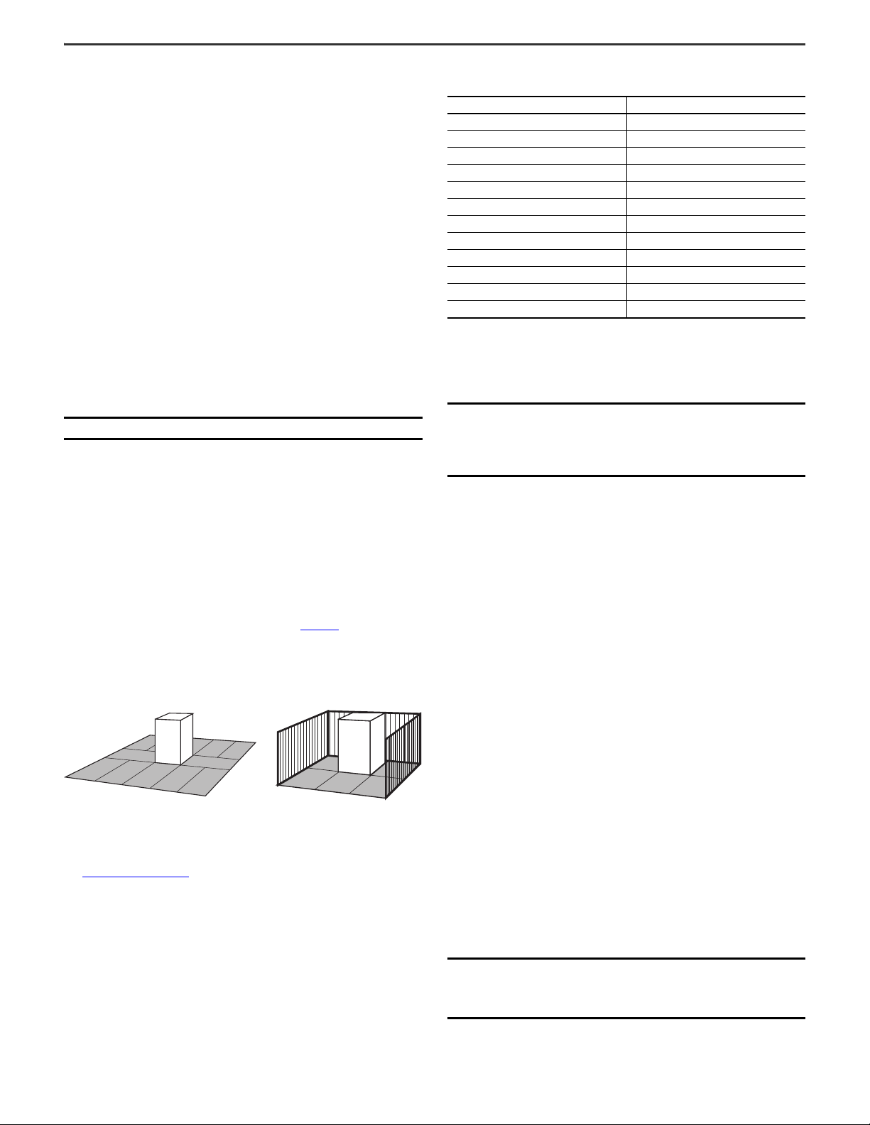
The recommended use of the safety mat system gives presence sensing over the
whole area where access is possible to the hazard (see Figure 12
safety mat system, for example, solely as a perimeter access guard, or as a
machine enabling device, are not recommended. If you are considering the safety
mat system for any application that is not covered by this manual, contact your
local Allen-Bradley distributor or Rockwell Automation sales office.
Figure 12 - Example Safety Mat Systems
). Other uses of the
Environment and Operating Conditions
See Specifications on page 2 and the information in this section to confirm that
there are no adverse factors that can compromise the integrity of the system.
Slip and Trip Hazards
Both safety mat patterns provide a non-slip surface under most conditions, but
must be kept free from large deposits of grease, soaps, or gels. If the straight rib
side is uppermost, we recommend that the ribs run across the hazard to give
improved grip.
Wear and Damage
Impacts from sharp or heavy objects can damage the outer surface of the safety
mat. After every such event, inspect the safety mat for deformation or punctures
and replace if necessary.
Safety mats are designed and tested to withstand one million operations in any
one spot. In use, do not exceed this number of operations in any single location.
Occasional heavy loads (for example, up to three ton trucks) are unlikely to damage
the safety mats, but do not use safety mats on traffic through routes.
Explosive Atmosphere
The system is not suitable for use in explosive atmospheres.
European EMC Directive
The safety mat system complies with the requirements of the European EMC
Directive. Normal operation under interference conditions, likely in industrial
environments, is verified and has been tested and certified.
IMPORTANT Special measures can be required in the presence of
6 Rockwell Automation Publication MATGRD-IN001C-EN-P - January 2024
abnormally high levels of E.M.I., for example, near to
welding or induction heating equipment, or near radio
transmitters or transceivers.
Page 7
MatGuard Pressure Sensitive Safety Mat System Installation Instructions
Safety
Mats
Confirm that covers and gratings are
flush with the surface of the floor.
Safety
Mats
No loose debris or protrusions.
No sharp edges.
Sensor mat must not
sag or undulate.
Hazard
Safety Mats
Arrows Show Access
Hazard
Fixed Guard
Safety Mats
Hazard
Extended Fixed Guard
Safety Mats
Floor
The floor or mounting surface for the safety mats must be flat, smooth, rigid, and
shows no perceptible distortion under the heaviest anticipated load. Undulations,
protrusions, large gaps, or other irregularities increase the sensitivity of the
sensor mats and can result in intermittent unintended switching off (nuisance
tripping).
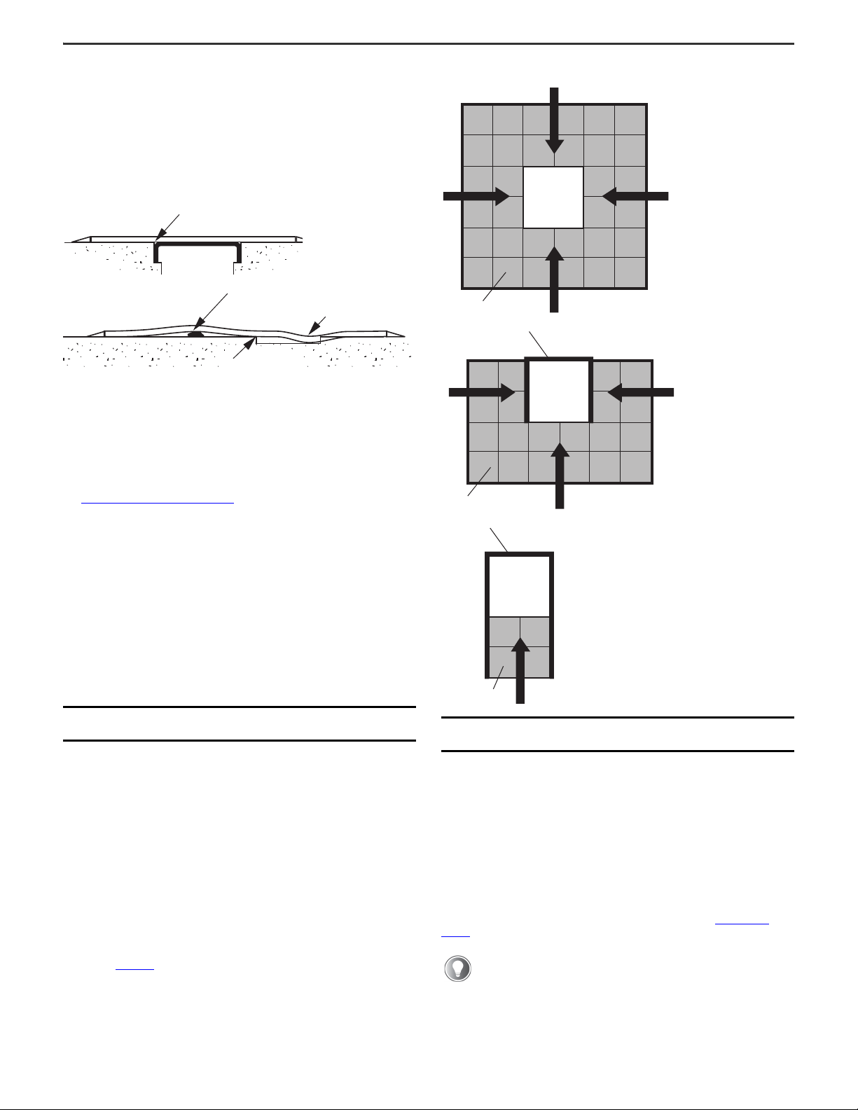
Figure 13 - Floor Conditions
Small and regular protrusions, such as a checker plate pattern, are acceptable.
Skimmed concrete floors are ideal. If any doubt exists, contact your local
Allen-Bradley distributor or Rockwell Automation sales office.
Control Unit Mounting
Figure 14 - Safety Mat Positioning
See Approximate Dimensions on page 21. Do not mount the control unit within the
detection zone.
If you require access to the control unit for manual reset or routine indicator
observation, mount the control unit at an accessible position outside the
protection zone that still provides a good view of the hazard and protection zone.
Situate the reset actuator outside the protection zone and in a position that gives
good visibility of the hazard and protection zone.
In other cases, you can mount the control unit can anywhere that is convenient
outside the protection zone that accommodates for the access requirements for
tests and maintenance.
Mount the 440F-C4000D control unit within an enclosure to a minimum of IP54 (in
accordance with EN 60529).
Safety Mat Positioning
Combined Trip and Presence Sensing Device
The position of the safety mat edges is calculated as a horizontal distance from
the hazardous zone. Define the hazardous zone as a volume and account for all
possible modes of the machine and all variations in the size of the workpiece. You
must record the dimensions, position of the hazardous zone, and the assumptions
that you use so you can check the adequacy of the safeguarding.
If you use other safeguarding measures with the safety mat system, those
measures can affect the requirements for the size and position of the safety mats,
as shown in Figure 14.
IMPORTANT The control unit is not suitable for direct exposure to
high-pressure cleaning.
Rockwell Automation Publication MATGRD-IN001C-EN-P - January 2024 7
IMPORTANT Fixed guards must meet the requirements of EN 14120 and
EN 13857.
First, ascertain one or more routes where you require unobstructed access to the
hazardous zone across the safety mat system. Consider all routine needs for
access, such as product inspection, machine inspection and adjustment, tool
changes, and the removal of blockages. Also consider visual observation of the
process. Consider the space requirements of persons and ancillary equipment
close to the machine during interventions.
Safety Distance Calculations
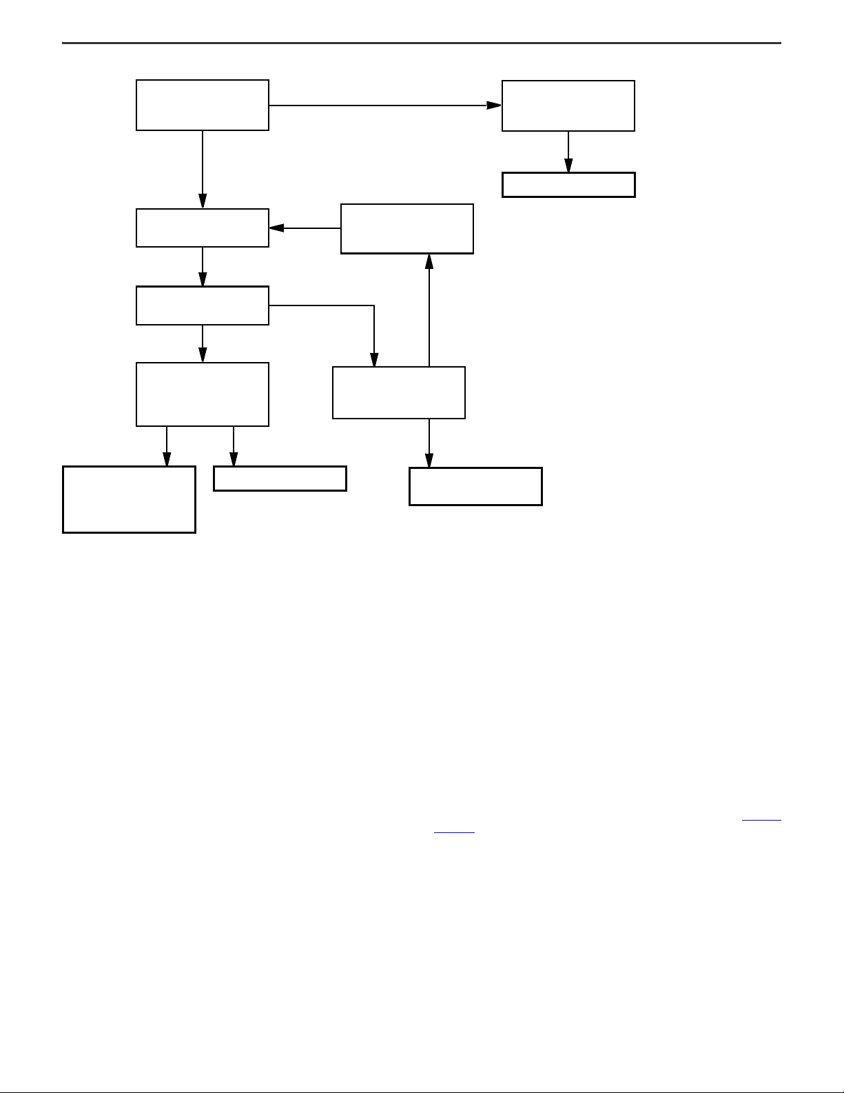
Applications that use the safety mat system as a combined trip and presence
sensing system must be done in accordance with EN 13855. See Figure 15 on
page 8.
If the machine is designed in conformity with an existing
harmonized European C type standard for that machine (which gives
specific formulas or minimum distances), use these standards in
preference to the standards given in EN 13855.
Page 8
MatGuard Pressure Sensitive Safety Mat System Installation Instructions
Are the specific formulas or
minimum distances given in the
type C standard?
Determine the minimum
distance according to the C type
standard.
Use this minimum distance.
YES
NO
Calculate the minimum distance
by the formulas in prEN 999.
Can this minimum distance be
achieved?
YES
Does the minimum distance
allow persons to be within the
danger zone without being
detected?
NO
Use this minimum distance.
YES
Use this minimum distance
together with supplemented
measures, depending on the
risk.
NO
Can the overall response time be
reduced, or can parameter C be
reduced?
NO
Use additional or alternative
protective equipment.
Reduce the overall response
time and/or reduce parameter
C.
YES
Figure 15 - Methodology Flowchart
The calculated minimum distance is the minimum horizontal distance from the
outer edge of the MatGuard safety mat system detection zone to the nearest part
of the hazard.
The EN 13855 formula for floor-mounted safety mats is:
S = (1600 x T) + 1200 mm
S is the minimum safety distance in millimeters.
The factor of 1600 is based on the standard assumption of 1600 mm/s
(63 in./s) as the approach speed.
T is the overall stopping time in seconds.
The added 1200 mm (47.24 in.) is parameter C given in EN 999 and
accounts for stride length and arm reach.
The overall stopping time T is the sum of two parts:
T = t1 + t2
t1 is the maximum time between actuation of the sensing function and the
output signal switching devices being in the off state.
For the MatGuard safety mat system, t1 = 35 ms.
t2 is the response time of the machine, that is, the time that is required to
stop the machine or remove the risks after receiving the output from the
MatGuard safety mat system.
The response time of the machine that is used in the calculation must be the worst
case time. Some machines have inconsistent response times, which are
dependent upon the mode of operation, the nature of the workpiece, and the point
in the operating cycle at which stopping is initiated. Allow for conditions that can
affect the response time, such as wear on brakes. Some circumstances can
require an allowance for further delays in the machine control system.
Calculation Example
In the following example, the MatGuard safety mat system is used with a machine
with a worst case response time measured as 0.485 seconds.
Using the formula,
T = t1 + t2
= 35 ms + 485 ms
= 520 ms = 0.520 s
S = (1600 x 0.520) + 1200 mm
= 832 + 1200 mm = 2032 mm
Safety mats are required from 2032 mm (80 in.) up to the edge of the machine
baseplate.
Presence Sensing System Within Perimeter Guarding Area
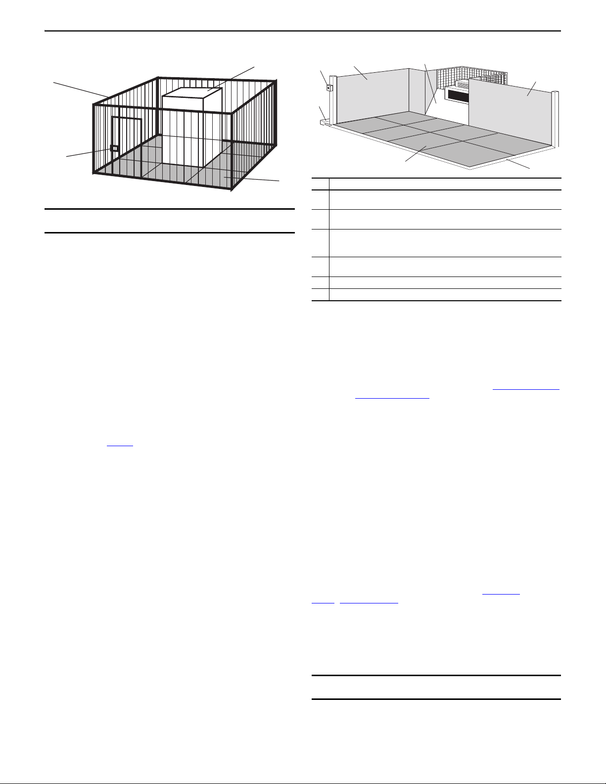
If the area around the hazard is enclosed within a guarded perimeter (see Figure 16
on page 9), the requirements of prEN 999 do not necessarily apply. In these
applications, the MatGuard safety mat system detects the presence of an operator
to help prevent reset of the perimeter-guarding system and the restart of the
machine while the operator is inside the enclosure.
8 Rockwell Automation Publication MATGRD-IN001C-EN-P - January 2024
Page 9
MatGuard Pressure Sensitive Safety Mat System Installation Instructions
Hazard
Safety Mats
Fixed Guards
Interlocked Door
(with locking)
1
2
6
4
5
1
3
Figure 16 - Guarded Perimeter
IMPORTANT Fixed guards must meet the requirements of EN 14120 and
EN 13857.
A suitable perimeter guarding system would be a fixed guard with an access door
that is fitted with an interlock switch with conditional guard unlocking (see
EN 14119). A trip device, such as a safety light curtain, can also be suitable for some
applications. Calculate the position of the safety light curtain according to
EN 13855.
Fixed Guards
Design the fixed guards must so that access is not possible to the hazardous zone
other than via the MatGuard safety mat. Guard construction and position must be
in accordance with EN 14120 and EN 13857.
Figure 17 - Bypass Prevention Best Practice
Item Description
Fixed guards help prevent access to the hazardous zone in such a way that there is
1
no access between the guard and sensors.
A sloping cover plate helps prevent the operator from avoiding the sensing area by
2
standing on the machine base plate.
A ramp at the point of access reduces the tripping hazard at the sensor edge. The
3
ramp can also protect connected cables. The optional perimeter trim is a ramp
section.
Cable trunking is installed outside of the fixed guard. This configuration helps
4
prevent against the misuse as access to the hazardous zone.
5 A Reset button is in a well-protected location that gives full visibility of the machine.
6 Safety mats are properly installed.
Electric Interfacing
The protection that the system provides depends on the correct interfacing
between the system and the machine.
Bypass Prevention
It must not be possible to reach the hazard without standing on the MatGuard
safety mats. Prevent access to the hazardous zone from positions that do not
involve standing on the MatGuard safety mats. This restricted access requires
additional angle plates and the careful position of pipework and trunking. Best
practice is shown in Figure 17.
The safety output contacts from the system are arranged as two independent
voltage free N.O. contact pairs. See the terminal positions in Installation on page 13
and ratings in Specifications on page 2.
The control unit conforms to Category 3 according to EN ISO 13849-1. In common
with other safety mats and floors, Category 3 performance for the safety mat
cannot be achieved for faults that result from severe mechanical damage or
long-term degradation. The safety mats conform to Category 1 according to
EN ISO 13849-1.
The system, which is composed of interconnected safety mats and a control unit,
meets the requirements of EN ISO 13849-1 Category 3.
Use the safety mat system as the sole protective measure or in combination with
other measures or devices (for example, safety light curtain, system of work).
Where a harmonized European C standard is available for the machine type, it
contains requirements and guidance for the safety-related control system of the
machine. EN ISO 13849-1 also provides guidance. You must provide an adequate
level of protection against foreseeable faults to the appropriate category of
EN ISO 13849-1. For this reason, we recommend you use a dual-channel
configuration with duplication and monitoring of the final switching elements
(contactors) on all higher risk applications.
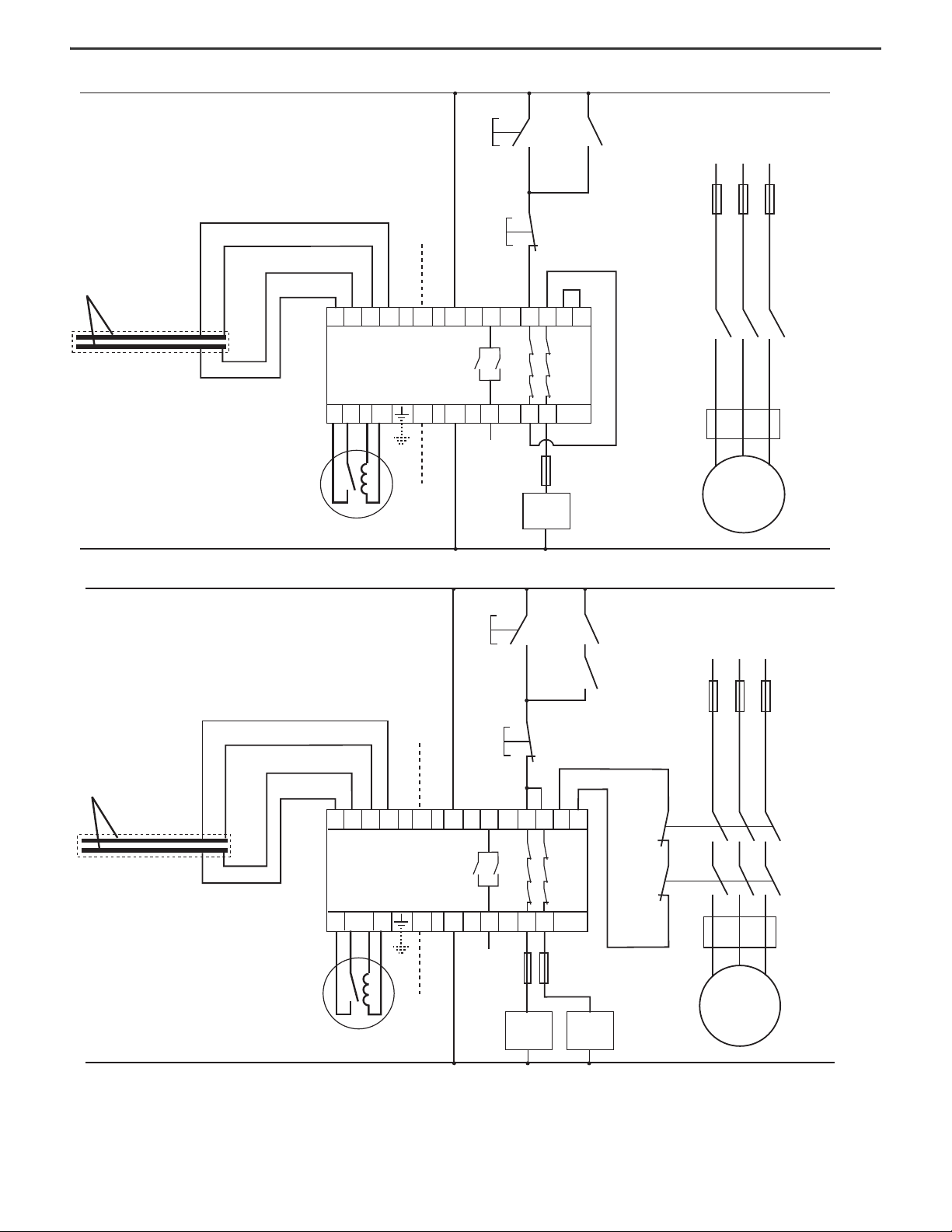
Examples of interconnections of the safety mat system (Figure 18 on
page 10…Figure 21 on page 11) show control unit applications with:
• Circuit status
• Supply power is on
• No presence on safety mat
• Reset button operated (if in Manual Reset mode)
• Machine start circuit enabled
IMPORTANT If one or both of the contactors stick on, the motor stops
when the safety mat is stood on and the fault is detected.
Rockwell Automation Publication MATGRD-IN001C-EN-P - January 2024 9
Page 10
MatGuard Pressure Sensitive Safety Mat System Installation Instructions
M
24VDC, SUPPLY
K1
L1 L2 L3
AUXILIARY OUTPUT
AUXILIARY INPUT
K1
START
(AUX)
MOMENTARY
PUSH
STOP
BUTTON
MOMENTARY
PUSH
BUTTON
FUSE
MOTOR
E.G. THERMAL
PROTECTION
CUT OUT
+
VE
12 3
CMCM4
CONTROL UNIT
K1
–VE
WHITE
WHITE
BLACK
BLACK
INTERNAL SENSOR
MAT PLATES
SENSOR MATS
L
N
LINK
LINK
31
13 23
32
14 24
N/O
110VAC, 230VAC SUPPLY
(ALTERNATIVE SUPPLY CONNECTION)
PB R IND
24V DC Supply
K1 (Aux)
Start
Momentary
Push-start
Stop
Momentary
Push-start
Link
Link
Fuse
Auxiliary Output Auxiliary Input
Motor
Protection
(Thermal
Cutout)
110VAC, 230V AC Supply
(Alternative Supply Connection)
Control Unit
Black
Black
White
White
Internal Safety Mat Plates
Safety Mats
M
K1
K2
24VDC, SUPPLY
L1 L2 L3
AUXILIARY OUTPUT
AUXILIARY INPUT
K1 (AUX)
K2 (AUX)
START
MOMENTARY
PUSH
BUTTON
STOP
MOMENTARY
PUSH
BUTTON
FUSES
MOTOR
PROTECTION
E.G. THERMAL
CUT OUT
+
VE
12 3
4
31
MC MC13 23
32
14 24
CONTROL UNIT
K1 K2
–VE
POSITIVELY
GUIDED
CONTACTOR
AUXILIARY
CONTACTS
L
N
110VAC, 230VAC SUPPLY
(ALTERNATIVE SUPPLY CONNECTION)
WHITE
WHITE
BLACK
BLACK
SENSOR MATS
INTERNAL SENSOR
MAT PLATES
N/O PB R IND
24V DC Supply
K1 (Aux)
Start
Momentary
Push-start
Stop
Momentary
Push-start
Fuse
Auxiliary Output Auxiliary Input
Motor
Protection
(Thermal
Cutout)
110VAC, 230V AC Supply
(Alternative Supply Connection)
Control Unit
Black
Black
White
White
Internal Safety Mat Plates
Safety Mats
K2 (Aux)
Positively
Guided
Contactor
Auxiliary
Contacts
Figure 18 - Single-channel Diagram - 440F-4000P and 440F-4000S Control Units
Figure 19 - Dual-channel Diagram - 440F-4000P and 440F-4000S Control Units
10 Rockwell Automation Publication MATGRD-IN001C-EN-P - January 2024
Page 11
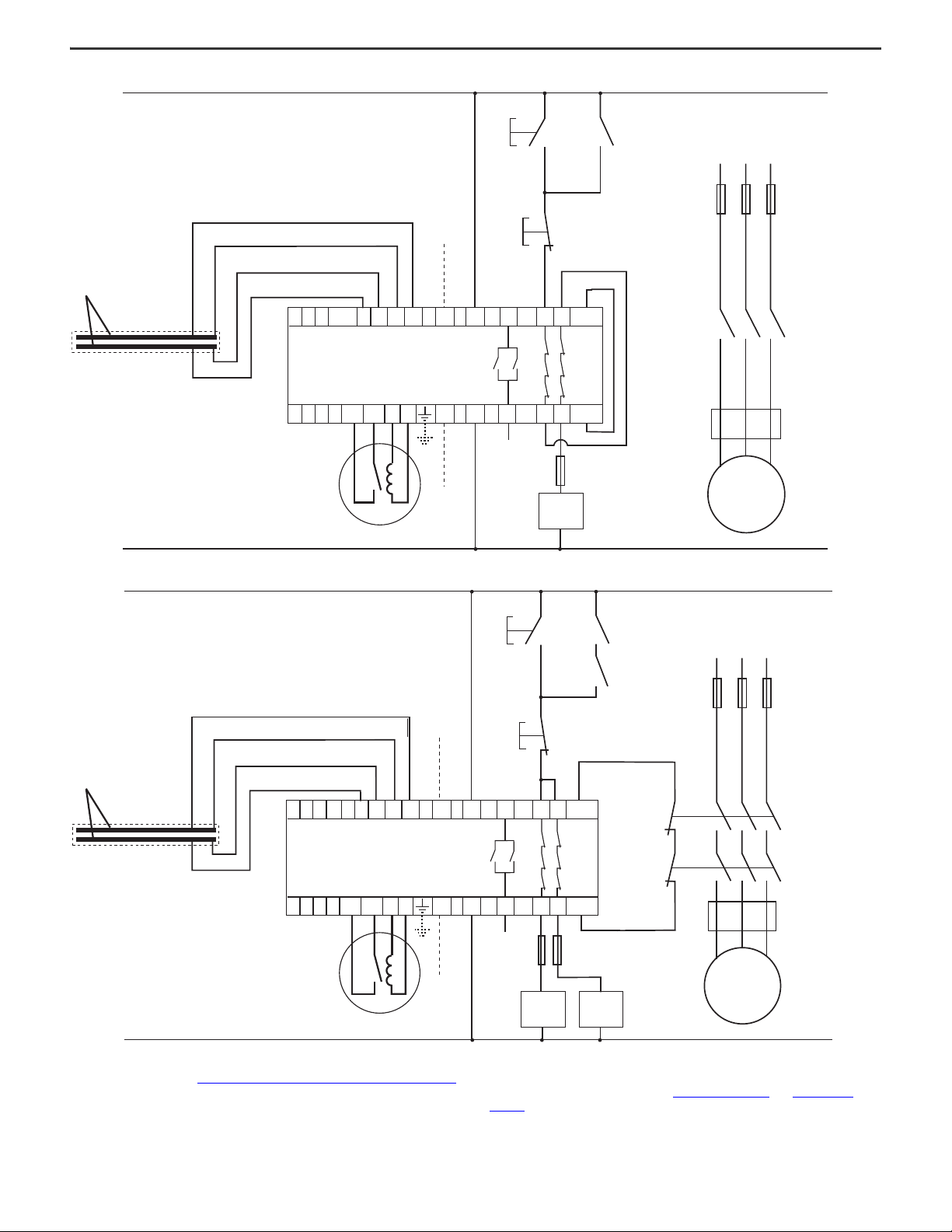
Figure 20 - Single-channel Diagram - 440F-4000D Control Unit
M
24VDC, SUPPLY
K1
L1 L2 L3
AUXILIARY OUTPUT
AUXILIARY INPUT
K1 (AUX)
START
MOMENTARY
PUSH
BUTTON
STOP
MOMENTARY
PUSH
BUTTON
FUSE
MOTOR
PROTECTION
E.G. THERMAL
CUT OUT
+
12 3
CM4
CONTROL UNIT
K1
–
WHITE
WHITE
BLACK
BLACK
SENSOR MATS
INTERNAL SENSOR
MAT PLATES
A1
A2
LINK
LINK
31
13 23
32
14 24
RESET
IND
RESET
INDY6Y4Y2
Y1 Y3 Y5
MC
110VAC, 230VAC SUPPLY
(ALTERNATIVE SUPPLY CONNECTION)
24V DC Supply
K1 (Aux)
Start
Momentary
Push-start
Stop
Momentary
Push-start
Link
Link
Fuse
Auxiliary Output Auxiliary Input
Motor
Protection
(Thermal
Cutout)
110VAC, 230V AC Supply
(Alternative Supply Connection)
Control Unit
Black
Black
White
White
Internal Safety Mat Plates
Safety Mats
Reset Reset
24V DC Supply
K1 (Aux)
Start
Momentary
Push-start
Stop
Momentary
Push-start
Fuse
Auxiliary Output Auxiliary Input
Motor
Protection
(Thermal
Cutout)
110VAC, 230V AC Supply
(Alternative Supply Connection)
Control Unit
Black
Black
White
White
Internal Safety Mat Plates
Safety Mats
K2 (Aux)
Positively
Guided
Contactor
Auxiliary
Contacts
Reset R eset
MatGuard Pressure Sensitive Safety Mat System Installation Instructions
Figure 21 - Dual-channel Diagram - 440F-4000D Control Unit
INTERNAL SENSOR
MAT PLATES
SENSOR MATS
After completion of the safety-related control system design, confirm that the
response time assumed in Combined Trip and Presence Sensing Device on page 7
remains valid. If the value changes, repeat the safety distance calculations.
24VDC, SUPPLY
BLACK
BLACK
WHITE
WHITE
Y5Y3Y1
Y6Y4Y2
12 3
CONTROL UNIT
RESETRESET
START
MOMENTARY
PUSH
BUTTON
110VAC, 230VAC SUPPLY
(ALTERNATIVE SUPPLY CONNECTION)
AUXILIARY INPUT
+
4
IND
IND
A1
A2
–
31
32
AUXILIARY OUTPUT
Next, consider the options for reset. Account for the consequences of the selected
reset scheme for hazards such as unexpected startup, both under normal
conditions and under fault conditions. Figure 22 on page 12 and Figure 23 on
page 12 show both reset modes of the MatGuard safety mat system.
STOP
MOMENTARY
PUSH
BUTTON
13 23
14 24
K1 K2
MC
MC
FUSES
K1 (AUX)
K2 (AUX)
POSITIVELY
GUIDED
CONTACTOR
AUXILIARY
CONTACTS
K1
K2
L1 L2 L3
M
MOTOR
PROTECTION
E.G. THERMAL
CUT OUT
Rockwell Automation Publication MATGRD-IN001C-EN-P - January 2024 11
Page 12
MatGuard Pressure Sensitive Safety Mat System Installation Instructions
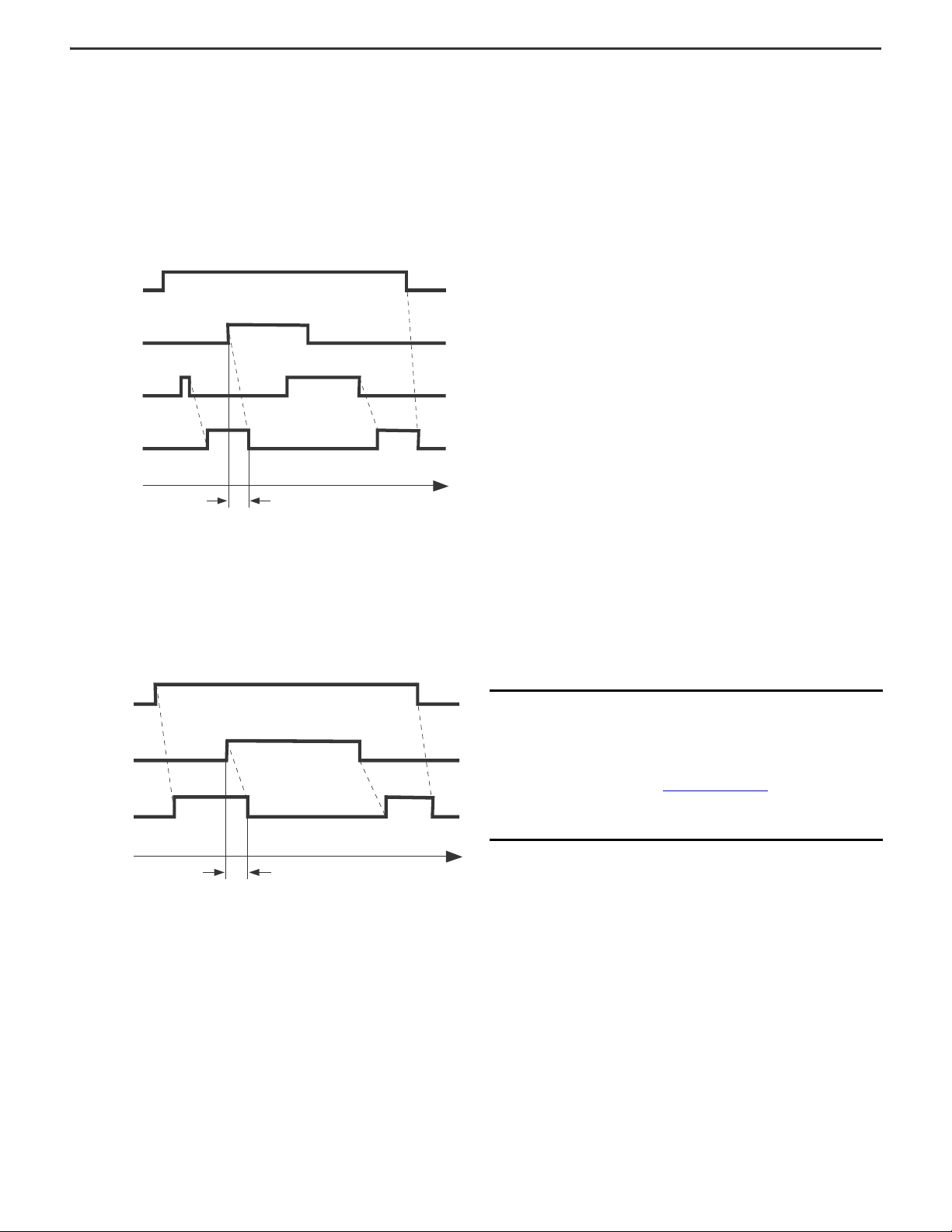
Relationship between actuation, reset, and output.
20 ms
Response time
Time
Power to
Mat Manager
Actuating
Force
Reset
Mat Manager
Safety Outputs
Relationship between actuation, reset, and output.
Time
20 ms
Response time
Power to
Mat Manager
Actuating
Force
Mat Manager
Safety Outputs
Reset Modes
Manual Reset Mode
To initiate manual reset, push and release a remotely mounted momentary Reset
button, or use voltage-free contacts within the machine safety-related control
system. The safety outputs of the safety mat manager remain off until reset after
power-up and can require primary/secondary reset circuits in complex systems
where other power-up interlocks (start interlocks) are present.
Figure 22 - Manual Reset Mode
Arc Suppression
We recommend arc suppression networks or devices for all inductive loads. For
safety circuits, suppressors must fit across the load and never across the
contacts. The supply and load characteristics determine the type and ratings of
the suppressors. Suppressors can increase response time, particularly suppressor
diodes across DC coils, and must be in place when you measure response times.
Contactor Monitoring
Contactor monitoring is provided via the two terminals marked MC. Use contactor
monitoring in all dual-channel, two contactor systems. If one of the contactors
fails to isolate the power, the safety mat control unit locks out and helps prevent
the re-energization of the other contactor until the fault is rectified.
Final Safety Mat Layout
After you consider the previous factors, check and finalize the safety mat layout.
Consider whether the machine response time changed from the initial
calculations.
Whenever possible, arrange safety mats with the wires at the outside edge of the
detection zone. This arrangement simplifies installation and replacement, if
necessary, and all wiring is protected by the perimeter trim.
Wiring
Auto Reset Mode
When used in Auto Reset mode, the control system of the machine requires a
separate reset function to help prevent machine startup when stepping off the
safety mat, or after a temporary power supply failure or dip.
Figure 23 - Auto Reset Mode
Auxiliary Output
An auxiliary output is a non-safety, status output. Use an auxiliary output, for
example, as a status import to the PLC in systems that use PLC functional machine
control in combination with hard wired safety circuits. Other uses include
diagnostics in protection schemes, and/or driving status lamps or alarms. The
safety function must not depend on this output.
Protect all system wiring from mechanical damage and suitably seal all wiring for
the operating environment. Waterproof butt connectors are supplied for safety
mat to safety mat connections and are protected by the edge trim. Where wire
runs are required across the floor, the 440F-T3230 wire guide provides suitable
protection. Use conduit or trunking for other wire runs. Use correctly sized and
tightened conduit fittings or cable glands to IP65 to maintain the sealing integrity
of the control unit.
Wiring practices must be in accordance with EN 60204-1 Clause 14.
IMPORTANT To isolate the 110/230V supply, separately rout the input
power supply to enter the control unit via separate fittings
or glands than those fittings that are used for the output
wiring. You can use conduit to bury wiring from the control
unit to the safety mat in the floor, or pass the wiring via the
edge trim. We recommend flexible conduit for this type of
installation. See Installation on page 13 for further details.
Determine the wiring method and determine the input and
output connection points for the safety mat to control unit
wiring.
Final Details
Prepare a work schedule and drawings of the system layout and the electrical
circuit. We recommend that you record and retain all measurements and
calculations in the technical file for the machine.
12 Rockwell Automation Publication MATGRD-IN001C-EN-P - January 2024
Page 13
MatGuard Pressure Sensitive Safety Mat System Installation Instructions
1
2
3
4
Safety Mats
White White White White
Black Black Black Black
White
Black
White
Black
Terminals at
Control Unit
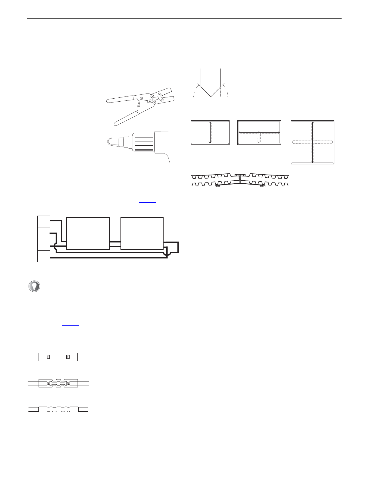
Strip wires 8 mm (0.31 in.) and insert
into the crimping barrel.
Crimp using the correct cavity size on
the crimp tool.
Heat crimped splice using heat gun
with deflector until tubing shrinks and
adhesive shrinks and flows.
45
45 °
°
Miter All Trims to 45°
As Shown in Mat Layouts
Mat 1 Mat 2
Mat 2 Mat 3
Mat 1
Mat 1 Mat 2
Mat 3 Mat 4
Installation
The system designer must supervise the installation and commissioning. A
mechanical technician and an electrician familiar with industrial wiring practices
are required for the installation.
Only a trained electrical technician with experience in safety installations can
perform the commissioning.
The following special tools are required:
• Crimp tool for pre-insulated
butt splice connectors
• Hot air gun with reflector
attachment for heat shrinking
Safety Mat Installation
Isolate and lock off the machine power supply at the source. Verify that the floor is
flat, smooth, clean, free of debris, and that any buried conduit or other wiring
provision is correctly in place. Unpack the safety mats; take care to keep the
safety mats flat and not to pull on the wires. Place the safety mats on the floor in
the planned positions with the connecting wires at the periphery of the detection
zone. Connect the safety mat sections together according to Figure 24.
Figure 24 - Safety Mat Connections
Unite Trim Mounting
Miter all active uniting trim sections that are used in the installation to 45°. Mitered
trim aids in installation and helps retain the overall sensitivity of the sensing area.
Figure 26 - Unite Safety Mats
Perimeter Trim Mounting
The safety mat wires have a black outer covering; two have a black
inner sheath and two have a white inner sheath (see Figure 24 for
positions).
Leave a sufficient wire tail length to enable the connection to be remade if a safety
mat must be replaced, but confirm that the interconnecting wires fit easily under
the edge trim without being crushed. Use the supplied butt connectors to join the
wires, as shown in Figure 25. Where the safety mat wires require extending (for
example, front safety mat to rear safety mat connections, and control unit
connections), use an extra pair of the butt connectors and a length of twin wire.
Figure 25 - Wire Connections
Where the wiring to the control unit is not buried, notch the perimeter trim at the
wire entry and exit positions, and cut the trim slope to suit the conduit system
selected. Notch the perimeter trim so that any flexing of the perimeter trim does
not trap the wiring. Confirm that there are no sharp edges or burrs that can
damage the wires.
Rockwell Automation Publication MATGRD-IN001C-EN-P - January 2024 13
Page 14
MatGuard Pressure Sensitive Safety Mat System Installation Instructions
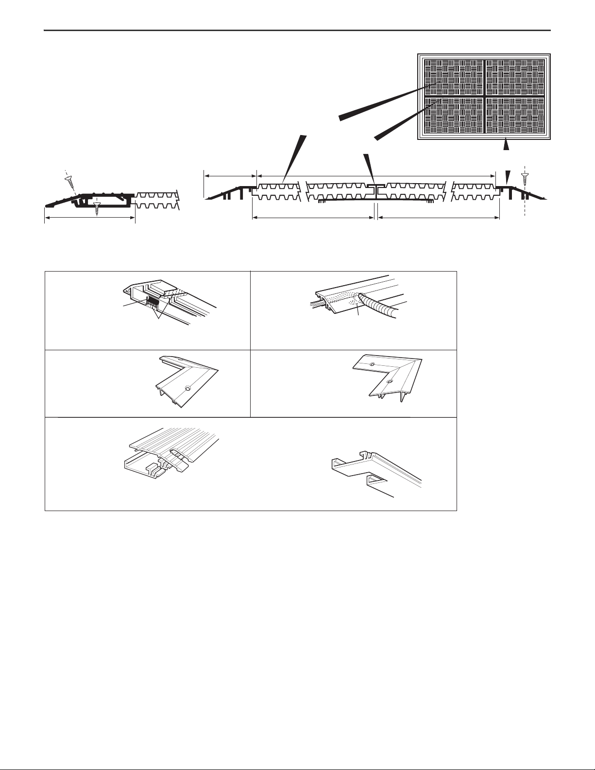
Safety Mat
Active
Uniting Trim
Detection Zone
Perimeter
Trim
Add 52 mm (2.05 in.) for each
standard perimeter trim
Add 10 mm (0.39 in.) for
each uniting trim joint
No. 6 x 9.5 mm (3/8 in.) self-tapping
screw (not supplied)
Normal Safety Mat SizeNormal Safety Mat Size
Add 95 mm (3.74 in.) for each
channel perimeter trim (Cat. No. NZG 3011)
Cat. No. 440F-T3210, 440F-T3310,
and 440F-T3510
Use edge grommets
over sharp edges
Cut slots here
Cat. No. 440F-T3210, 440F-T3310,
and 440F-T3510
Flexible conduit
Strain relief
clamp
Use a strain relief clamp with flexible conduit
Cat No. 440F-T3012
Aluminum external corner perimeter trim
(Use with Cat No. 440F-T3510,
440F-T3310, and 440F-T3210)
Cat No. 440F-T3013
Aluminum internal corner perimeter trim
(Use with Cat No. 440F-T3510,
440F-T3310, and 440F-T3210)
Cat No. 440F-T3211 and 440F-T3411
Suggested cut-out for
flexible conduit entry
Suggested cut-out for
safety mat wires entering
cable trunk (base of
perimeter trim)
For external corner trim, use Cat No. 440F-T3014. For internal corner trim, use Cat No. 440F-T3015.
Figure 27 - Perimeter Trim and Uniting Trim Showing Detection Zone
Figure 28 - Details of Trim Mounting
the safety mat. Use the holes in the trim as a guide to mark out and drill the floor
(fit plugs if necessary). Clean off the floor and use countersunk screws that are
suited to the application to mount the safety mats and edge trim in place.
As you fit the perimeter trim, confirm that none of the wiring is trapped or crushed
between the trim and the floor or the top and bottom sections (depending on trim
type).
Use a strain relief clamp where the wiring exits the perimeter trim wherever wires
can be caught or pulled. Protect all wiring in suitable conduit. If possible, the wiring
Mark out the edge trim mounting positions on the floor, allowing the trim to overlap
and conduit must not cross a floor area where it is a tripping hazard. If crossing
the floor is unavoidable, enclose the wiring and conduit within the 440F-T3230
protective wire guide.
14 Rockwell Automation Publication MATGRD-IN001C-EN-P - January 2024
Page 15
MatGuard Pressure Sensitive Safety Mat System Installation Instructions
341223 2413 1431 32MCMCN/O PB R IND
–ve
NL
+ve
AM
230 110
1
2
3
75 69
4
10
11
Mode set
MANUAL
AUTO
Voltage set
110V
230V
24V
Date
tick boxes
8
Secondary Fuse
500 mA
Primary
Fuse
500 mA
Machine-enabled
Green
Manual Reset
Mode Green
Power
Green
Auto Reset Mode
Green
Status Indicators
Remote Reset
Term in als
Remote Reset
Indication
Term in als
Contactor
Monitoring
Term in als
Auxiliary
Term in als
Safety Output
Term in als
White
White
Black
Black
Mat Connection
Term in als
32
31
42
41
34
33
14
13
24
23
MC
MC
IND
R
PB
NO
–
ve
NL
+ve
230V110V
AUTO RESET
MANUAL RESET
24V
N/C AUXILIARY
TERMINALS
N/O AUXILIARY
N/C MONITORED
OUTPUT
TERMINALS
TERMINALS
SAFETY
OUTPUT
CONTACTOR
MONITORING
TERMINALS
TERMINALS
REMOTE
RESET
TERMINALS
MAT 1
MAT 2
MAT 3
MAT 4
MAT 5
MAT 6
MAT 7
MAT 8
REMOTE
RESET INDICATION
TERMINALS
3
4
6
5
7
9
8
10
4
1
2
12
11
Mode set
MANUAL
AUTO
Voltage set
110V
230V
24V
Date
tick boxes
N.C. Auxiliary
Ter min als
N.O. Auxiliary
Ter min als
Safety
Output
Ter min als
N.C. Monitored
Output
Ter min als
Contactor
Monitoring
Ter min als
Remote Reset Indication
Ter min als
Remote
Reset
Ter min als
Manual Reset
Auto Reset
A1• +
RESET IND
1 2 MC Y1 Y3 Y5
•
•
13 23 31
LN
110/230V AC
SUPPLY
A2
RESET IND
3 4 MC Y2 Y4 Y6
•
•
110/230VAC selectable
14 24 32
24V AC/DC
24V AC/DC
SUPPLY
CONTACTOR
CONTROL
POWER
AUXILIARY
OPTIONAL
REMOTE
INDICATION UNIT
POWER
GREE
AUTO RESET MOD
GREEN
MANUAL RESET M
GREEN
MACHINE ENABLE
GREEN
BLACK
BLACK
WHITE
WHITE
Y1 Y2 Y3 Y4 Y5 Y6
Fuse replacement
UP 110V SUPPLY
DOWN 230V SUPPLY
500 mAT
AUTOMATIC
MANUAL
1
2
3
4
11
5
67
10
89
Mode set Voltage set
MANUAL
AUTO
Date
110v
230v
24v
tick boxes
Machineenabled
Green
Manual Reset
Mode Green
Power
Green
Auto Reset
Mode Green
Auxiliary
Contactor
Control
Power
Optional
Remote
Indication Unit
White
Black
Black
White
24V AC/DC
Supply
110/230V AC
Supply
110/230VAC
selectable
Fuse Replacement
Up 110V Supply
Down 230V Supply
Automatic
Manual
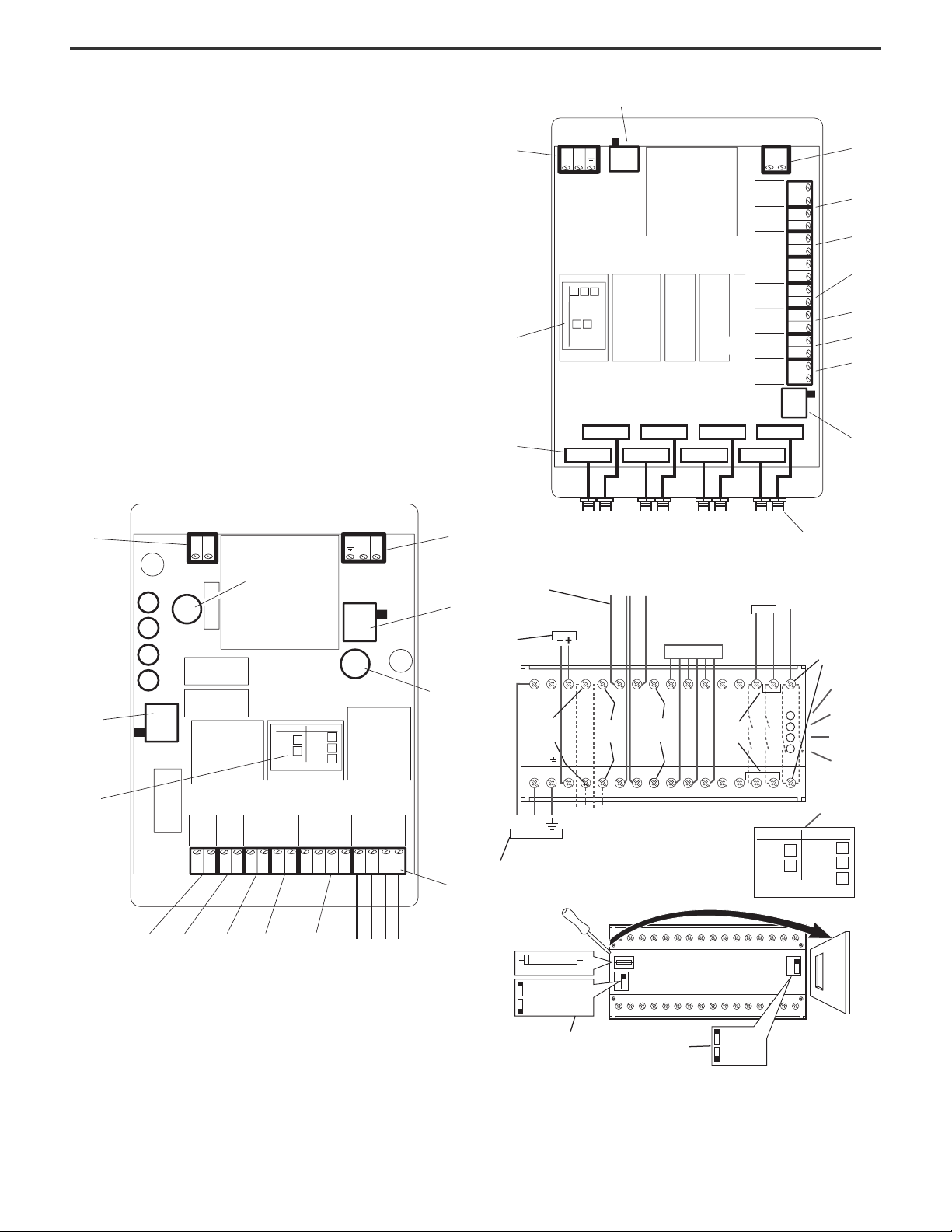
Control Unit Installation and Wiring
Only install the control unit as supplied. Do not modify or subject the control unit to
any procedures or connections other than what is described in this manual.
To prepare the 440F-C4000P control unit, carefully knock out the cable entry
positions to be used. Rout the input power separately and enter the control unit via
a separate entry than the output wiring. Mount the control unit in the planned
position. All wiring to the control unit terminals must use either the supplied wire
type, or multi-strand conduit cable, switchgear cable, or equipment wire with
0.5…1.5 mm
ingress protection rating of IP65 to achieve cable entry into the 440F-C4000P
control unit. Confirm that the glands or adapters are of a suitable size and are fully
tightened.
Only use the supplied insulated pin crimps. This wire and terminal combination
avoids the possibility of shorts from loose strands or open circuits that
overtightening or vibration can cause.
Only use a suitable ratchet type crimp tool. Crimp onto both the conductor and the
insulation. Do not connect multiple wires onto one crimp.
Verify that the power supply remains isolated and locked off until
Check the Electrical Functions on page 16.
Externally fuse the main AC supply at the point of supply by a 500 mA maximum
high rupture capacity (HRC) fuse. Fuse the neutral side of the supply to the same
specification, unless it is referenced to earth.
Figure 29 - 440F-C4000P and 440F-C4000S Control Unit Wiring
2
(30…16 AWG) conductors. Use glands or adapters that provide an
Figure 30 - 440F-C28013 Mat Manager Wiring
Rockwell Automation Publication MATGRD-IN001C-EN-P - January 2024 15
Figure 31 - 440F-C4000D Control Unit Wiring
Page 16
MatGuard Pressure Sensitive Safety Mat System Installation Instructions
Shorting Plug
Installation Procedure
1. Switch the voltage selector switch to 110V or 230V as appropriate to match
the supply voltage.
The system is factory set at 230V AC.
2. If you use a 110V or 230V AC supply, wire to the terminals shown, including
a protective earth. Check the setting on the voltage selector switch, set in
step 1
. Do not make any connections to the terminal shown in step 3. The
size of the protective earth wire must be at least equal to that of the
supply wire.
3. If you use a 24V AC/DC supply, connect to the terminals shown to deliver
the correct polarity. Do not make any connections to the terminals shown
in step 2. With 24V AC, the earthed pole of the power supply must connect
to the terminal (–ve).
4. Safety mat connections: Connect the leads from the safety mat to the
terminals shown. 1=White, 2=White, 3=Black, 4=Black.
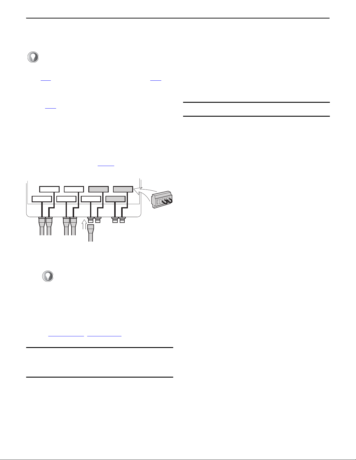
440F-C28013 mat manager: Eight quick-connect adaptors that are labeled
1…8 are on the base of the unit and provide connection to the safety mats.
If less than eight mats connect to the control unit, the other connections
must end with the supplied shorting plugs. The required safety mats must
connect in sequence (1...8) to the quick connect adaptors on the outside of
the unit. To end unused connectors, unplug fitted connectors and replace
with shorting plugs as shown in Figure 32
Figure 32 - Connect/Terminat Safety Mat Connections
MAT 2
MAT 1
MAT 3
MAT 4
MAT 5
5. The auxiliary outputs terminal provides auxiliary N.C. contacts (for
example, closed when the machine-enabled status indicator is off)
suitable for indication or alarm devices. The auxiliary N.C. contacts must
not be connected to the safety circuit.
MAT 6
.
MAT 8
MAT 7
Shorting Plug
7. Remote reset N.O. terminals are provided for the connection of a remote
Reset button.
Catalog numbers 440F-C4000P, 440F-C4000S, and 440F-C28013: If there
is not a full view of the hazardous zone from the control unit, disconnect
the wires from the reset switch on the control unit lid at the terminal block
to disable the reset function at the control unit.
8. The reset indication (if used) with an illuminated push-button remote reset
switch, shows when the safety mat system must reset. Remote reset
indication terminals are for connection to the bulb (28V).
9. Set the manual reset/auto reset (M/A switch) to the required setting.
M = Manual Reset mode
A = Auto Reset mode
IMPORTANT Disconnect the machine prime mover from the final
contactors so that no machine movement can take place.
10. Mark and sign the label according to the established voltage and mode
settings.
11. Recheck the wiring connections including connections or modifications
that were made to the machine control system wiring. Replace the lid.
Secure the lid on the relevant units.
Check the Mechanical Installation
1. Check that safety mats, perimeter trim, and uniting trims are undamaged
and correctly positioned and secured. Check that the designed safety
distance is achieved.
2. Check that access to the hazardous zone is not possible other than via the
safety mat and that any fixed guards are positioned according to the
design and are secure.
3. Check that the presence of a person between the hazardous zone and the
safety mat system is restricted.
4. Check that the environmental conditions, present or foreseeable,
correspond to conditions considered during the design stage.
5. Check that the installation is free of hazards that were not foreseen at the
design stage.
6. Check that any warning notices are in place.
7. Check that any other required protective measures are installed.
MGCSM1 and MGCSM4 offer N.C. and N.O. contacts.
Safety outputs are volt free terminals for connection to the machine
safety circuit; safety outputs connect in series with the machine contactor
control circuit (max rating 250V, 4 A). Protect safety outputs externally
with suitably rated fuses.
For one contactor, use terminals 13 and 24 with terminals 14 and 23 linked.
For two contactors with two independent control circuits (dual-channel
system), use terminals 13 and 14 for connection to one contactor control
circuit and terminals 23 and 24 for connection to the other.
See Figure 18 on page 10
…Figure 21 on page 11 for examples of typical
interfacing with the machine control circuit.
IMPORTANT The safety outputs must connect directly via hard wiring to
the machine primary control elements (contactors). Safety
outputs must not connect via any elements such as
ordinary relays or PLCs not suitably specified for
safety-related functions.
6. The control unit is provided with contactor monitoring terminals linked.
When the link is removed, terminals can connect to positively guided N.C.
auxiliary contacts on the machine contactors to provide monitoring of the
contactors in dual-channel control systems. If one contactor fails to
isolate the power at de-energisation of its control coil, the safety mat
control unit does not allow the other contactor to energize until the fault is
rectified.
Check the Electrical Functions
Manual Mode Only (Not for 440F-C28013 Mat Manager)
1. Check the status indicators on the control unit:
• Power indicator (green) illuminates
• Manual Reset indicator (green) illuminates
• Reset lamp in the Reset button illuminates
• Machine-enabled indicator (green) is off
2. Press and release the Reset button.
a. Verify that the machine-enabled status indicator illuminates and the
reset lamp turns off.
b. Stand on the safety mat and check that the machine-enabled status
indicator turns off.
3. Step off the safety mat, check that the machine-enabled status indicator
remains off and the Reset button illuminates.
• Press and release the Reset button, check that the machineenabled status indicator illuminates and the Reset button turns off.
4. To check the remote Reset buttons and lamps (if fitted), repeat the
previous tests.
5. To check the correct operation of any status monitoring that is connected
to the safety mat system, repeat the previous steps.
16 Rockwell Automation Publication MATGRD-IN001C-EN-P - January 2024
Page 17

MatGuard Pressure Sensitive Safety Mat System Installation Instructions
Auto Reset Mode Only (Not for 440F-C28013 Mat Manager)
1. Check the status indicators on the control unit:
• Power indicator (green) illuminates
• Machine-enabled indicator (green) illuminates
2. Stand on the safety mat and check that the machine-enabled status
indicator turns off.
3. Step off the safety mat, check that the machine-enabled status indicator
illuminates.
4. To check the correct operation of any status monitoring that is connected
to the safety mat system, repeat the previous steps.
440F-C28013 Control Unit Functions
Auto Reset Mode Only
1. Check the status indicators on the control unit:
• Power indicator (green) illuminates
• Machine-enabled indicator (green) illuminates
• The channel fault status indicators 1...8 (green) illuminate,
matching the number of safety mats installed.
2. Stand on safety mat number 1 and check that the machine-enabled status
indicator turns off and the channel fault status indicator changes to red.
3. Step off the safety mat and check that the control system returns to the
same state as step 1
4. Repeat the process for each safety mat that is connected to the control
unit. Check that the corresponding channel fault status indicator changes
to red.
.
Manual Reset Mode Only
1. Check the status indicators on the control unit:
• Power indicator (green) illuminates
• Machine-enabled indicator (green) illuminates
• The channel fault status indicators 1...8 (green) illuminate,
matching the number of safety mats installed.
2. Stand on safety mat number 1 and check that the machine-enabled status
indicator turns off and the channel fault status indicator changes to red.
3. Step off the safety mat, operate the Reset button to reset the system
manually, and then check that the control system returns to the same
state as step 1
4. Repeat the process for each safety mat that is connected to the control
unit. Check that the corresponding channel fault status indicator changes
to red.
Channel fault status indicators indicate individual safety mat
operation or fault.
.
Mode of Operation (440F-C28013 Mat Manager)
Auto Reset
• On power-up: Power, auto reset, and machine-enabled status indicators
illuminate.
• When the safety mat operates: Machine-enabled status indicator turns off.
• Stand off the safety mat: Machine-enabled status indicator illuminates.
Under Fault Condition
Machine-enabled status indicator turns off and does not allow reset until the fault
is rectified. In the fault condition, if there is a safety mat fault, one or more of the
safety mat status indicators illuminate. Under an open circuit or short circuit, the
indicators illuminate red. If there is a fault condition and none of the safety mat
status indicators illuminate, then the fault is a control unit fault.
Check Safety Functions
Single-channel Systems
See Figure 18 on page 10 and Figure 20 on page 11.
Simulate normal operation. Stand on the safety mat to actuate and check that the
main contactor drops out immediately. Check that any other safety-related stop
functions like the brake or clutch contactors are operating as intended.
Dual-channel Systems
See Figure 19 on page 10 and Figure 21 on page 11.
1. Simulate normal operation. Stand on the safety mat to actuate and check
that both final contactors drop out immediately. Check that any other
safety-related stop functions like the brake or clutch contactors are
operating as intended.
2. Isolate the power source and then short circuit terminals 13 and 14 at
terminal block 6 to install a temporary fault (see Figure 29 on page 15
Figure 30 on page 15).
3. Reinstate the power source and actuate the safety mat and check that one
of the final contactors drops out immediately and any other stop functions
that are associated with that channel operate as intended.
4. Check that the control unit does not reset.
5. Isolate the power source and remove the temporary fault. Reinstate the
power source and check that the safety mat system operates normally.
Take the same electrical safety precautions and repeat the test with a
temporary short circuit across terminals 23 and 24 at terminal block 6 (see
Figure 29 on page 15
6. Again, check that the control unit does not reset.
7. Remove the temporary fault, check that the safety mat system operates
correctly.
or Figure 30 on page 15).
All System Types
1. Conduct any other tests required to confirm that the safety-related control
system meets the requirements of its category according to
EN ISO 13849-1, and works as intended.
2. Check any other safety functions associated with the machine circuits
that the installation of the safety mat system can affect. You must have an
existing procedure for these tests.
3. Isolate the machine power supply at the source.
4. Reconnect any automatic reset function provided by the machine control
system.
5. Reconnect the machine prime mover to the final contactors.
6. Secure all covers and doors.
or
Manual Reset
• On power-up: Power, manual reset, and machine-enabled status indicators
illuminate.
• Press the Reset button: Machine-enabled status indicator illuminates.
• When the safety mat operates: Machine-enabled status indicator turns off.
• Stand off the safety mat: Machine-enabled status indicator is still off.
• Press the Reset button: Machine-enabled status indicator illuminates.
Rockwell Automation Publication MATGRD-IN001C-EN-P - January 2024 17
Page 18

MatGuard Pressure Sensitive Safety Mat System Installation Instructions
Functional Checkout
Reinstate the machine electrical supply. Check the following:
1. Machine operation cannot commence until the safety mat control unit is
reset. Perform the walking test described in Routine Inspection and Test
on page 18.
2. Check that actuation of the safety mat stops hazardous movement.
3. Check that the machine does not start, but does enable restart, when you
step off the safety mat.
4. Check that when approaching the machine at a walking pace, hazardous
movement stops before the hazardous zone can be reached. In critical
applications, conduct stop-time tests.
5. If any type of muting system is installed, check that the safety mat system
is muted only during non-hazardous parts of the operating cycle and that
any mute indicators operate correctly.
6. Test the emergency stop function of the machine.
Commissioning
Before putting the machine into its normal service, confirm that operators and
supervisors are aware of the nature and purpose of the safety mat system and that
they understand the functions of the controls and indicators.
Confirm that the technical specifications together with inspection, test, and
service instructions are available to the appropriate personnel and that a system is
in place to record inspections.
Confirm that personnel understand that no additional coverings, boards, plates, or
planks are allowed on the safety mat during operation of the machine.
Routine Inspection and Test
We recommend weekly routine inspections.
1. Stop the machine. Clean the safety mats and allow them to dry. Inspect the
top surface of the safety mat for damage. Minor nicks and abrasions of the
vinyl cover are acceptable, but immediately address any damage that
exposes the metal plate.
2. Check that the perimeter trim and uniting trim are not cracked, broken, or
distorted and are mounted securely. Replace damaged parts immediately.
3. Test the safety mat operation. Two persons are required, one to walk on
the safety mat, the other to observe the control unit. On systems that use
Manual Reset mode, continually press and release the Reset button.
a. Check that the machine-enabled status indicator is on before
actuation of the safety mat, and turns off as soon as the safety mat is
stepped on.
b. Walk over each section of the safety mat and each joining section in
turn. Stand with both feet on the same uniting trim between two
sections. The machine-enabled status indicator must remain off
during the entire time.
c. Step off the safety mat, operate the Reset button. Check that the
machine-enabled status indicator illuminates.
d. Start the machine, step onto the safety mat and check that the
machine stops immediately.
4. Check that all barriers such as fixed guards and angle plates are in place,
undamaged, and securely mounted. If these checks reveal any problems,
do not allow the use of the machine until they are rectified. Record the
inspection and test in a written log.
Thorough Examination and Test
Maintenance
During maintenance operations, disconnect the prime mover of the machine
before you work on the safety mat system. Observe electrical safety precautions.
Safety Mat Cleaning
Regularly sweep the safety mats clear of deposits such as swarf and other
materials. Use warm water and detergent to wash or hose down the safety mats to
clean or remove buildup, such as grease, if necessary. Do not use solvents.
We recommend thorough inspections every 6 months or after damage.
Contact your local Allen-Bradley distributor or Rockwell Automation sales office for
information on an authorized testing service. A person who is competent in
electrical and mechanical engineering must perform the tests. Two persons are
required, one to walk on the safety mat, the other to observe the control unit.
1. Conduct the Routine Inspection and Test
2. Isolate the power source to the machine and safety mat system. Observe
electrical safety precautions.
3. Inspect the safety mat components thoroughly for mechanical damage.
4. Disconnect the wires to the safety mat at terminals 1…4 at the MatGuard
control unit.
5. Connect the two white wires to one test input of an ohmmeter and connect
the two black wires to the other input. Walk over each section of the safety
mat and each joining section in turn. Stand with both feet on the same
uniting trim between two sections until all areas of the safety mat are
covered. The maximum resistance with presence on the safety mat must
not exceed 100 Ω.
If these checks reveal any problems, do not allow the use of the machine until you
rectify the problems.
Check that the stopping performance of the machine has not deteriorated from
the stopping performance that was used in the original safety distance
calculations. Record the inspection and test in a written log.
.
18 Rockwell Automation Publication MATGRD-IN001C-EN-P - January 2024
Page 19

MatGuard Pressure Sensitive Safety Mat System Installation Instructions
Dismantle and Disposal
To dismantle the safety mat system, the procedure is the reverse of the
installation, with no extra hazards.
Confirm that the machine and safety mat system power is isolated and locked off
at the source before starting work.
If the system is to be reconfigured or relocated, observe the handling precautions
that are given in System Configuration on page 6. The safety mat system does not
contain any hazardous materials that require special precautions for disposal.
Fault Finding
Disconnect the prime mover before working on the safety mat control system with
power applied.
Observe electrical safety precautions.
No Start
With no presence on the safety mat and after following the correct reset
procedure, the machine does not start.
1. If the machine-enabled indicator on the safety mat control unit is on, there
is a probable fault on the machine or the control system external to the
safety mat system.
a. Check the external fuses in the control unit safety output wiring and
replace if necessary. Confirm that the correct value of the fuse is used
(2 A max).
b. Record the replacement in the inspection log. If either fuse blows
immediately or requires early replacement, there is a probable fault in
the machine control circuit between the safety output of the safety
mat control unit and the final control elements (contactors) of the
machine.
2. If the machine-enabled status indicator on the safety mat control unit is
off:
a. Check that the power status indicator is illuminated. If it is not, check
the power supply to the safety mat control unit.
b. Check that the power supply connects to the appropriate terminals.
c. Check the primary and secondary fuses in the control unit and replace
if necessary. Confirm that the correct value of fuse is used
(500 mA anti-surge) for both primary and secondary fuses.
d. Record the replacement in the inspection log. If either fuse blows
immediately or requires early replacement, contact your local
Allen-Bradley distributor or Rockwell Automation sales office.
3. If the machine-enabled status indicator on the safety mat control unit is
off and the power status indicator is on, there is a fault in the system. On
dual-channel systems with contactor monitoring, if the external safety
output fuses did not blow, it is still probable that there is a fault external to
the control unit. One fault in either wiring channel can cause the safety
mat control unit to lock off the safety outputs until the fault is rectified
and the control unit is reset.
a. Check that all connecting wiring in the system is configured correctly
and is not damaged and that both contactors are functioning correctly.
b. Rectify any faults and, if in Manual Reset mode, press and release the
control unit Reset button.
4. If the problem is not resolved, contact your local Allen-Bradley distributor
or Rockwell Automation sales office.
No Stop
The machine does not stop or can start with presence on the safety mat.
Do not allow use of the machine with presence on the safety mat.
1. Check that the machine-enabled status indicator is illuminated on the
safety mat control unit.
2. If the machine-enabled status indicator is not illuminated, there is a
probable fault on the machine or the control system external to the safety
mat system. Do not allow use of the machine until the fault is rectified and
tested.
3. If the machine-enabled status indicator is illuminated, do not allow use of
the machine and contact your local Allen-Bradley distributor or
Rockwell Automation sales office immediately.
Repair
ATTENTION: Before working on the safety mat system or
machine control system, isolate the power source to the
machine and safety mat system. Observe electrical safety
precautions.
User repairs are limited to replacement by new safety mat system parts. If
problems occur, return the units to your Allen-Bradley distributor.
Use the recommended butt splice connectors to make any repairs to the
connecting wires.
Tampering with components parts invalidate the warranty.
The warranty is invalid if the quality seal is broken on the DIN rail control unit.
Rockwell Automation Publication MATGRD-IN001C-EN-P - January 2024 19
Page 20

MatGuard Pressure Sensitive Safety Mat System Installation Instructions
Replacement Parts
Safety Mat Size Safety Mat
Millimeters Inches
500 x 500 19.7 x 19.7
500 x 600 19.7 x 23.6
500 x 900 19.7 x 35.4
500 x 1000 19.7 x 39.4
500 x 1200 19.7 x 47.2
500 x 1500 19.7 x 59.1
600 x 600 23.6 x 23.6
600 x 750 23.6 x 29.5
600 x 900 23.6 x 35.4
600 x 1000 23.6 x 39.4
600 x 1200 23.6 x 47.2
600 x 1500 23.6 x 59.1
750 x 500 29.5 x 19.7
750 x 750 29.5 x 29.5
750 x 1500 29.5 x 59.1
800 x 600 31.5 x 23.6
800 x 750 31.5 x 29.5
800 x 900 31.5 x 35.4
800 x 1000 31.5 x 39.4
800 x 1200 31.5 x 47.2
800 x 1500 31.5 x 59.1
900 x 900 35.4 x 35.4
900 x 1000 35.4 x 39.4
900 x 1200 35.4 x 47.2
900 x 1500 35.4 x 59.1
1000 x 750 39.4 x 29.5
1000 x 1000 39.4 x 39.4
1000 x 1200 39.4 x 47.2
1000 x 1250 39.4 x 49.2
1000 x 1500 39.4 x 59.1
Cat. No. Cat. No.
440F-M1010BYNN 440F-T1010
440F-M1012BYNN 440F-T1012
440F-M1018BYNN 440F-T1018
440F-M1020BYNN 440F-T1020
440F-M1024BYNN 440F-T1024
440F-M1030BYNN 440F-T1030
440F-M1212BYNN 440F-T1212
440F-M1215BYNN 440F-T1215
440F-M1218BYNN 440F-T1218
440F-M1220BYNN 440F-T1220
440F-M1224BYNN 440F-T1224
440F-M1230BYNN 440F-T1230
440F-M1510BYNN 440F-T1510
440F-M1515BYNN 440F-T1515
440F-M1530BYNN 440F-T1530
440F-M1612BYNN 440F-T1612
440F-M1615BYNN 440F-T1615
440F-M1618BYNN 440F-T1618
440F-M1620BYNN 440F-T1620
440F-M1624BYNN 440F-T1624
440F-M1630BYNN 440F-T1630
440F-M1818BYNN 440F-T1818
440F-M1820BYNN 440F-T1820
440F-M1824BYNN 440F-T1824
440F-M1830BYNN 440F-T1830
440F-M2015BYNN 440F-T2015
440F-M2020BYNN 440F-T2020
440F-M2024BYNN 440F-T2024
440F-M2025BYNN 440F-T2025
440F-M2030BYNN 440F-T2030
Standard Perimeter
Trim Kit
Item Specification Cat. No.
Standard perimeter trim 2 m (6.56 ft)
Standard perimeter trim 3 m (9.84 ft)
Standard perimeter trim 5 m (16.4 ft)
External corner standard perimeter trim Internal corner standard perimeter trim Perimeter trim with cable channel 2 m (6.56 ft)
Perimeter trim with cable channel 4 m (13.12 ft)
External corner perimeter trim with cable
channel
Internal corner perimeter trim with cable
channel
Active uniting trim Vinyl wire guide -
Safety mat control units -
Fuse 500 mA
Shorting plug -
-
-
440F-T3210
440F-T3310
440F-T3510
440F-T3012
440F-T3013
440F-T3211
440F-T3411
440F-T3014
440F-T3015
440F-T3020
440F-T3230
440F-C4000P
440F-C4000S
440F-C4000D
440F-C28013
440R-A31562
440F-A28639
For special-sized safety mats, refer to the model number printed on the label.
After replacing any parts, you must conduct the inspection and test that is shown
in Routine Inspection and Test on page 18. Pay special attention to those parts that
were replaced.
IMPORTANT After maintenance or repair operations, correctly refit all
edging trims, fastenings, and cable protection. Failure to do
this step, the use of non-approved parts, or modifications
can prevent the safety mat system from achieving its
specified performance.
20 Rockwell Automation Publication MATGRD-IN001C-EN-P - January 2024
Page 21
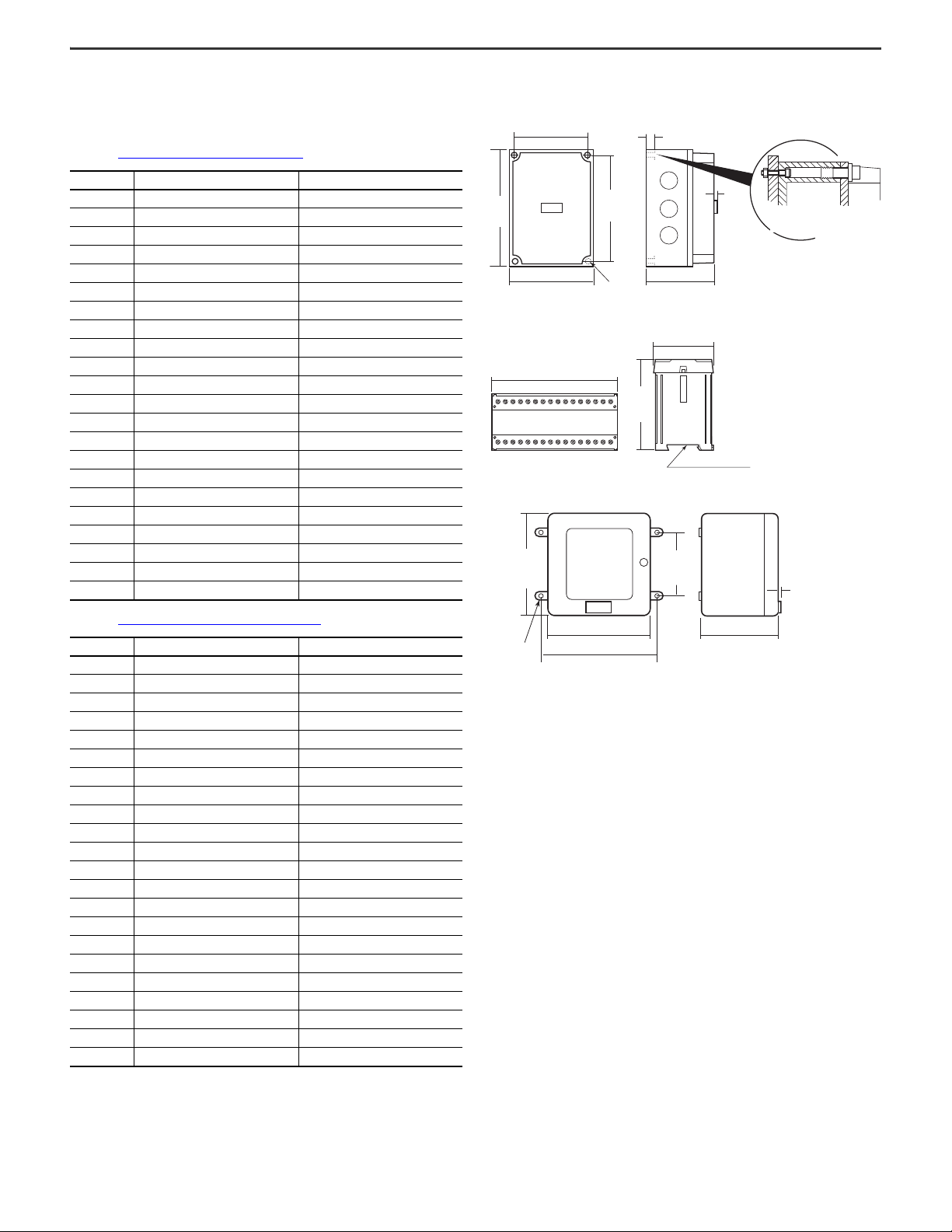
MatGuard Pressure Sensitive Safety Mat System Installation Instructions
Use mounting holes at the
bottom of the lid mounting
holes
152 (6.0)
DIN Rail [35 (1.38)]
120
(4.7)
73 (2.9)
DIN Rail [35 (1.38)]
Service
For service and assistance, contact your local Allen-Bradley distributor or
Rockwell Automation sales office.
Record of Routine Inspection and Test on page 18 (weekly)
Date Inspected By Comments
Approximate Dimensions
Figure 33 - 440F-C4000P Control Unit (Polycarbonate) [mm (in.)]
113.5 (4.5)
180
(7.1)
163.5
(6.4)
4 x M4 (0.16)
Figure 34 - 440F-C4000D Control Unit (DIN Rail) [mm (in.)]
Figure 35 - 440F-C4000S Control Unit and 440F-C28013 Mat Manager (Steel)
[mm (in.)]
10 (0.39)
75 (3.0)130 (5.2)
11
(0.43)
Use fixing holes at
bottom of lid fixing holes
Record of Thorough Examination and Test
Date Inspected By Comments
on page 18 (every 6 months)
4 x M6
(0.23)
230
(9.1)
210 (8.3)
225 (8.9)
165
(6.5)
11 (0.43)
143 (5.6)
Rockwell Automation Publication MATGRD-IN001C-EN-P - January 2024 21
Page 22

MatGuard Pressure Sensitive Safety Mat System Installation Instructions
Declaration of Conformity
CE Conformity
Rockwell Automation declares that the products that are shown in this document
conform with the essential requirements of the 2014/30/EU EMC Directive and
2006/42/EC Machinery Directive.
For a comprehensive CE certificate visit: rok.auto/certifications.
UKCA Conformity
Rockwell Automation declares that the products that are shown in this document
are in compliance with the essential requirements of the UK 2016 No. 1091 –
Electromagnetic Compatibility Regulations and 2008 No. 1597 – Supply of
Machinery (Safety) Regulations.
For a comprehensive UKCA certificate visit: rok.auto/certifications.
22 Rockwell Automation Publication MATGRD-IN001C-EN-P - January 2024
Page 23

Notes:
MatGuard Pressure Sensitive Safety Mat System Installation Instructions
Rockwell Automation Publication MATGRD-IN001C-EN-P - January 2024 23
Page 24
Rockwell Automation Support
Use these resources to access support information.
Technical Support Center Find help with how-to videos, FAQs, chat, user forums, Knowledgebase, and product notification updates. rok.auto/support
Local Technical Support Phone Numbers Locate the telephone number for your country. rok.auto/phonesupport
Technical Documentation Center Quickly access and download technical specifications, installation instructions, and user manuals. rok.auto/techdocs
Literature Library Find installation instructions, manuals, brochures, and technical data publications. rok.auto/literature
Product Compatibility and Download Center (PCDC) Download firmware, associated files (such as AOP, EDS, and DTM), and access product release notes. rok.auto/pcdc
Documentation Feedback
Your comments help us serve your documentation needs better. If you have any suggestions on how to improve our content, complete the form at rok.auto/docfeedback.
Waste Electrical and Electronic Equipment (WEEE)
At the end of life, this equipment should be collected separately from any unsorted municipal waste.
Rockwell Automation maintains current product environmental compliance information on its website at rok.auto/pec.
Rockwell Otomasyon Ticaret A.Ş. Kar Plaza İş Merkezi E Blok Kat:6 34752 İçerenköy, İstanbul, Tel: +90 (216) 5698400 EEE Yönetmeliğine Uygundur
Allen-Bradley, expanding human possibility, GuardMaster, MatGuard, and Rockwell Automation are trademarks of Rockwell Automation, Inc.
Trademarks not belonging to Rockwell Automation are property of their respective companies.
Publication MATGRD-IN001C-EN-P - January 2024 | Supersedes Publication MATGRD-IN001B-EN-P - April 2006
Copyright © 2024 Rockwell Automation, Inc. All rights reserved. Printed in the U.S.A.
26190
28563 Ver 03
 Loading...