

Page 1
Direct Drive Technology
Demonstration Machine
Quick Start
Page 2
Important User Information
Solid state equipment has operational characteristics differing from those of electromechanical equipment. Safety Guidelines for the
Application, Installation and Maintenance of Solid State Controls (publication SGI-1.1
office or online at http://literature.rockwellautomation.com
) describes some important differences between solid state equipment and
hard-wired electromechanical devices. Because of this difference, and also because of the wide variety of uses for solid state equipment, all
persons responsible for applying this equipment must satisfy themselves that each intended application of this equipment is acceptable.
In no event will Rockwell Automation, Inc. be responsible or liable for indirect or consequential damages resulting from the use or
application of this equipment.
The examples and diagrams in this manual are included solely for illustrative purposes. Because of the many variables and requirements
associated with any particular installation, Rockwell Automation, Inc. cannot assume responsibility or liability for actual use based on the
examples and diagrams.
No patent liability is assumed by Rockwell Automation, Inc. with respect to use of information, circuits, equipment, or software described
in this manual.
Reproduction of the contents of this manual, in whole or in part, without written permission of Rockwell Automation, Inc., is prohibited.
Throughout this manual, when necessary, we use notes to make you aware of safety considerations.
available from your local Rockwell Automation sales
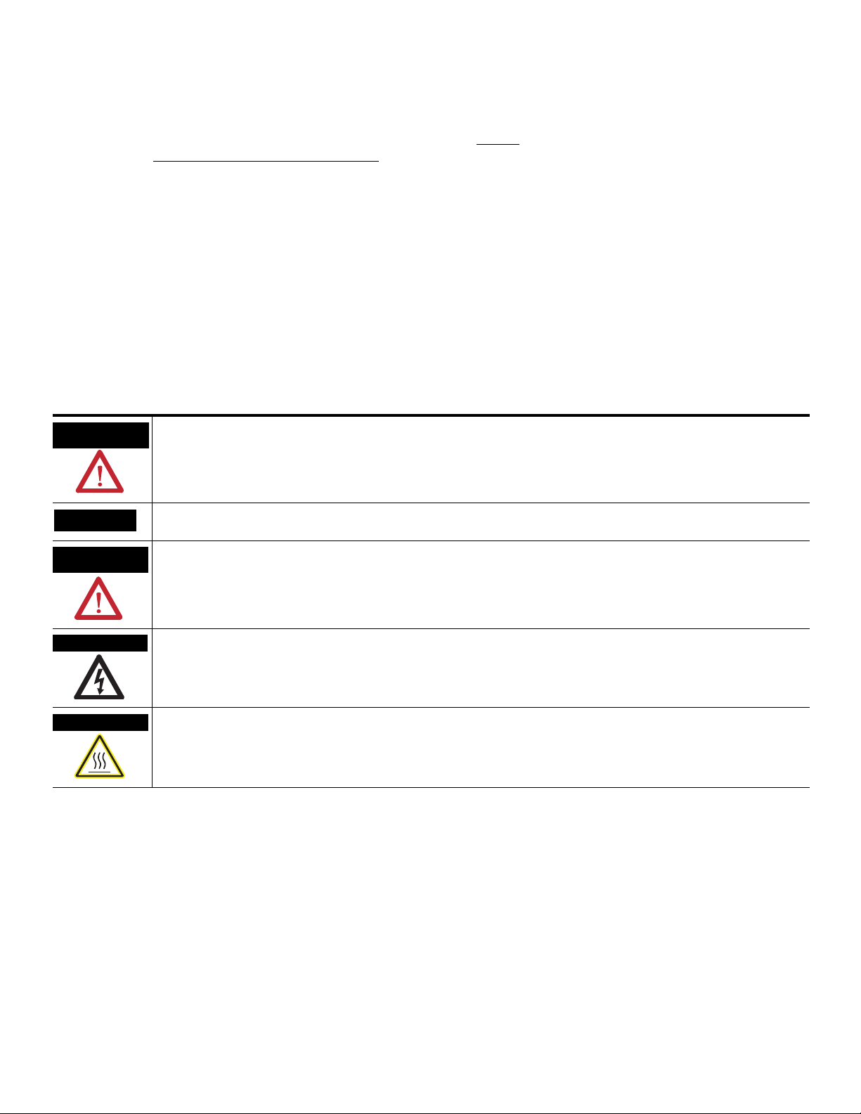
WARNING
IMPORTANT
ATTENTION
SHOCK HAZARD
BURN HAZARD
Identifies information about practices or circumstances that can cause an explosion in a hazardous environment, which may
lead to personal injury or death, property damage, or economic loss.
Identifies information that is critical for successful application and understanding of the product.
Identifies information about practices or circumstances that can lead to personal injury or death, property damage, or economic
loss. Attentions help you identify a hazard, avoid a hazard, and recognize the consequence
Labels may be on or inside the equipment, for example, a drive or motor, to alert people that dangerous voltage may be present.
Labels may be on or inside the equipment, for example, a drive or motor, to alert people that surfaces may reach dangerous
temperatures.
Rockwell Automation, Allen-Bradley, TechConnect, PanelView, PowerFlex 4, PowerFlex 40, PowerFlex 40P, PowerFlex 400, RSLogix 500, DriveExplorer, SLC, and MicroLogix are trademarks of Rockwell Automation, Inc.
Trademarks not belonging to Rockwell Automation are property of their respective companies.
Page 3

Install the Direct Drive Technology Demonstration Machine
Table of Contents
Preface
About This Publication . . . . . . . . . . . . . . . . . . . . . . . . . . . . . . . . . . . . . . 5
Audience. . . . . . . . . . . . . . . . . . . . . . . . . . . . . . . . . . . . . . . . . . . . . . . . . . 5
Parts List. . . . . . . . . . . . . . . . . . . . . . . . . . . . . . . . . . . . . . . . . . . . . . . . . . 5
Chapter 1
Introduction . . . . . . . . . . . . . . . . . . . . . . . . . . . . . . . . . . . . . . . . . . . . . . . 7
Before You Begin. . . . . . . . . . . . . . . . . . . . . . . . . . . . . . . . . . . . . . . . . . . 7
What You Need . . . . . . . . . . . . . . . . . . . . . . . . . . . . . . . . . . . . . . . . . . . . 7
Follow These Steps . . . . . . . . . . . . . . . . . . . . . . . . . . . . . . . . . . . . . . . . . 8
Position and Level Machine. . . . . . . . . . . . . . . . . . . . . . . . . . . . . . . . . . . 8
Remove Shipping Clamps . . . . . . . . . . . . . . . . . . . . . . . . . . . . . . . . . . . . 9
Install Signs. . . . . . . . . . . . . . . . . . . . . . . . . . . . . . . . . . . . . . . . . . . . . . . 12
Assemble Computer and Computer Stand . . . . . . . . . . . . . . . . . . . . . . 13
Make Connections . . . . . . . . . . . . . . . . . . . . . . . . . . . . . . . . . . . . . . . . . 14
Preparing the Direct Drive Technology Demonstration Machine for
Shipment. . . . . . . . . . . . . . . . . . . . . . . . . . . . . . . . . . . . . . . . . . . . . . . . . 14
Using the Direct Drive Technology Demonstration Machine
Specifications and Dimensions
Chapter 2
Introduction . . . . . . . . . . . . . . . . . . . . . . . . . . . . . . . . . . . . . . . . . . . . . . 15
Before You Begin. . . . . . . . . . . . . . . . . . . . . . . . . . . . . . . . . . . . . . . . . . 15
What You Need . . . . . . . . . . . . . . . . . . . . . . . . . . . . . . . . . . . . . . . . . . . 15
Follow These Steps . . . . . . . . . . . . . . . . . . . . . . . . . . . . . . . . . . . . . . . . 16
Machine Start Up . . . . . . . . . . . . . . . . . . . . . . . . . . . . . . . . . . . . . . . . . . 16
Start Computer Application. . . . . . . . . . . . . . . . . . . . . . . . . . . . . . . . . . 17
Machine Shut Down . . . . . . . . . . . . . . . . . . . . . . . . . . . . . . . . . . . . . . . 17
Using Push Button Switches and Door Interlock to Run the
Machine. . . . . . . . . . . . . . . . . . . . . . . . . . . . . . . . . . . . . . . . . . . . . . . . . . 18
Emergency Stop. . . . . . . . . . . . . . . . . . . . . . . . . . . . . . . . . . . . . . . . 18
Stop. . . . . . . . . . . . . . . . . . . . . . . . . . . . . . . . . . . . . . . . . . . . . . . . . . 18
Run . . . . . . . . . . . . . . . . . . . . . . . . . . . . . . . . . . . . . . . . . . . . . . . . . . 18
Front and Back Doors. . . . . . . . . . . . . . . . . . . . . . . . . . . . . . . . . . . 18
Using the Application to Control the Machine. . . . . . . . . . . . . . . . . . . 19
Appendix A
Introduction . . . . . . . . . . . . . . . . . . . . . . . . . . . . . . . . . . . . . . . . . . . . . . 21
Environmental Specifications for the Direct Drive Technology
Demonstration Machine . . . . . . . . . . . . . . . . . . . . . . . . . . . . . . . . . . . . 21
Direct Drive Technology Demonstration Machine Specification . . . . 21
Rockwell Automation Support . . . . . . . . . . . . . . . . . . . . . . . . . . . . . . . 24
Installation and Parts Assistance for Direct Drive Technology
Demonstration Machine . . . . . . . . . . . . . . . . . . . . . . . . . . . . . . . . . 24
3Publication PMC-QS002B-EN-P - October 2008 3
Page 4

Table of Contents
4 Publication PMC-QS002B-EN-P - October 2008
Page 5

Preface
About This Publication
Audience
Parts List
Use this quick start to setup the Direct Drive Technology Demonstration
Machine. This quick start describes the necessary tasks to install and run this
demonstration machine.
This quick start is for anyone who will be setting up Direct Drive Technology
Demonstration Machine for demonstration purposes only.
This quick start uses the following hardware.that is shipped with the
demonstration machine.
Quantity Description
1 Direct Drive Technology Demonstration Machine
1 Touch screen with computer configured with ControlLogix software
1 Infrared keyboard, mouse with receiver kit
1 Computer power cord
1 Hex wrench set
1 Adjustable crescent wrench
1 Pole with two support clamps
1 Wheel base
1 Keyboard and mouse support assembly
1 Direct Driver Technology sign
1 Build It, Buy It, Customize It sign
5Publication PMC-QS002B-EN-P - October 2008 5
Page 6

Preface
6 Publication PMC-QS002B-EN-P - October 2008
Page 7

Chapter
Install the Direct Drive Technology Demonstration Machine
1
Introduction
Before You Begin
In this chapter, you will install Direct Drive Technology Demonstration
Machine.
Topic Page
Before You Begin 7
What You Need 7
Follow These Steps 8
Position and Level Machine 8
Remove Shipping Clamps 9
Install Signs 12
Assemble Computer and Computer Stand 13
Make Connections 14
Preparing the Direct Drive Technology Demonstration Machine for
Shipment
• The packing material can be saved for use when the machine is
returned.
• Choose an installation location that is within 2 m (6.5 ft) of power
mains and meets the environmental and power specification for
the machine.
• The machine and the boxed contents of the shipping crate should
be brought to the location of the installation.
14
What You Need
7Publication PMC-QS002B-EN-P - October 2008 7
• Utility knife or snip for cutting tie wraps.
• Hex wrench set and an adjustable crescent wrench. These tools
were shipped with the machine.
• Additional tie wraps have been included. Use them to repack the
machine.
Page 8
Chapter 1 Install the Direct Drive Technology Demonstration Machine
Follow These Steps
Position and
Level Machine
Position and Level Machine
Remove
Shipping
Clamps
Complete the following steps to install the Direct Drive Technology
Demonstration Machine.
Install Signs
Assemble
Computer and
Computer
Stand
Make
Connections
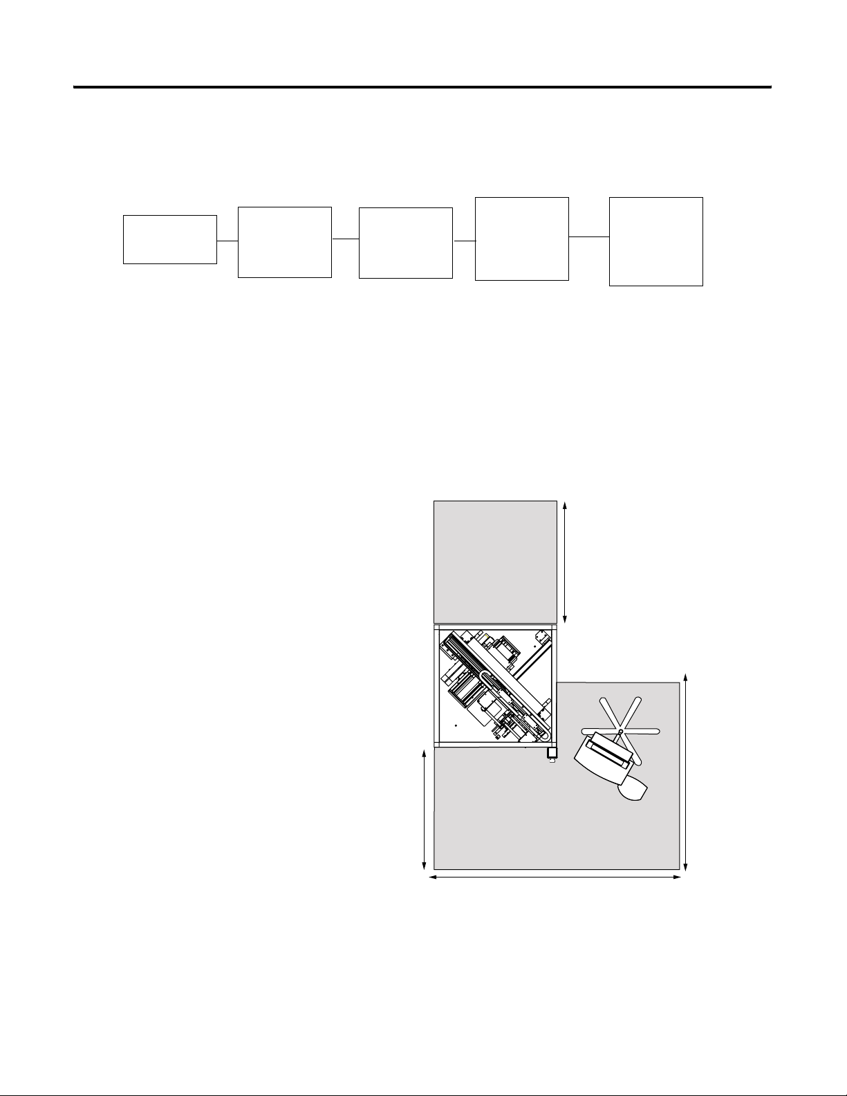
1. Position machine within 2 m (6.6 ft) of power source and with
1 m (3.3 ft) clearance in the front, back and right side of the
machine.
The position can be adjusted while the casters are supporting the
machine.
Dimensions m (ft)
1 (3.3)
1.5 (5)
1 (3.3)
2 (6.6)
2. Extend the four leveling feet so the full weight of the machine is
off the caster and on the leveling feet.
8 Publication PMC-QS002B-EN-P - October 2008
Page 9

Install the Direct Drive Technology Demonstration Machine Chapter 1
3. Adjust the leveling feet so the machine is visually level.
Casters not shown
Remove Shipping Clamps
1. Cut the tie wrap holding the power cable to the back door handle.
2. Remove the 8M Socket Head Cap Screw (SHCS) (X2) and the 6M
SHCS (X4) from the bridge brace and remove brace.
8M SHCS (X2)
6M SHCS (X4)
Publication PMC-QS002B-EN-P - October 2008 9
Page 10

Chapter 1 Install the Direct Drive Technology Demonstration Machine
3. Remove the cantilever axis shipping brackets at each end of the
stage.
a. Remove the 8M SHCS and washers from the bridge riser.
b. Loosen but don’t remove the 6M SHCS from the stage.
c. Push the stage forward and slide the bracket off the stage.
10 Publication PMC-QS002B-EN-P - October 2008
Page 11

Install the Direct Drive Technology Demonstration Machine Chapter 1
3M SHCS
6M SHCS
A
B
4. Remove the shipping bracket from each carriage on the dual stage
and from the cantilevered axis carriage.
a. Loosen but don’t remove the 3M SHCS.
b. Back off the 6M SHCS until they clear the carriage.
c. Slide the shipping bracket off the end of the stage.
There are two tie wraps that secure the LEU stage. One through the last hole in the magnet channel and one through the loop created by the tie wrap and around the motor assembly.
5. Carefully cut and remove the tie wraps.
Publication PMC-QS002B-EN-P - October 2008 11
Page 12
Chapter 1 Install the Direct Drive Technology Demonstration Machine
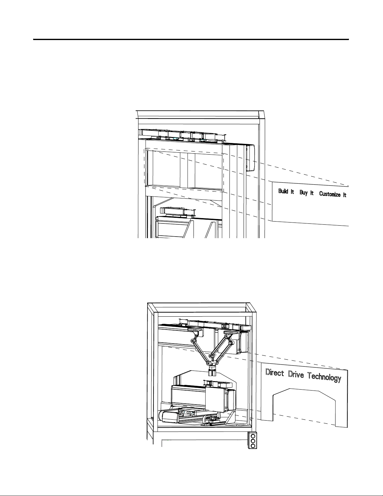
Install Signs
1. Attach the Build It, Buy It, Customize It sign to the back of the
bridge by aligning the Velcro strips.
If adjustment is necessary do not bend the sign. It could be permanently damaged.
2. Attach the Direct Drive Technology sign to the front of the
bridge by aligning the sign to the edge of the bridge.
If adjustment is necessary do not bend the sign. It could be
permanently damaged.
12 Publication PMC-QS002B-EN-P - October 2008
Page 13

Install the Direct Drive Technology Demonstration Machine Chapter 1
Assemble Computer and Computer Stand
1. Insert the uncapped end of pole in wheel base.
50 mm (2 in.) Pole
Wheel Base
2. Loosen the 4M BHCS on the back of the computer monitor and
slide into the keyholes of the Centris bracket and tighten all four
screw.
Centris Bracket
M4 BHCS (X4)
3. Attach the swing arm keyboard assembly on to the post of the
pole clamp.
Swing Arm
Keyboard Tray
Pole Clamp
Publication PMC-QS002B-EN-P - October 2008 13
Assy
Page 14

Chapter 1 Install the Direct Drive Technology Demonstration Machine
Make Connections
1. Attach the keyboard USB and mouse infrared receiver to the
Velcro on the support arm with the sensor side towards the
keyboard.
2. Connect the USB and mouse cable to computer.
3. Connect computer power and network cable to the side of the
machine.
4. Place mouse and keyboard on stand.
Emergency Stop,
Stop, Run Buttons
Main Power
Switch
Computer
Power Cord
Preparing the Direct Drive Technology Demonstration Machine for Shipment
Keyboard and Mouse
Infrared Receiver
5. Connect the machine to a 230V AC, 10 A minimum single phase
power main.
To prepare the Direct Drive Technology Demonstration Machine for
shipment pack the machine following the installation instructions in
reverse. Reuse the packing material and the tie wraps that were sent with
the machine.
Network Cable
14 Publication PMC-QS002B-EN-P - October 2008
Page 15

Chapter
Using the Direct Drive Technology Demonstration Machine
2
Introduction
Before You Begin
In this chapter, you will start the Direct Drive Technology
Demonstration Machine and learn how to control it using the hardware
buttons and the RSLogix Software application.
Topic Page
Before You Begin 15
What You Need 15
Follow These Steps 16
Machine Start Up 16
Start Computer Application 17
Using Push Button Switches and Door Interlock to Run the Machine 18
Using the Application to Control the Machine 19
Complete installation instruction in Chapter 1. Check that back door is
secured.
What You Need
15Publication PMC-QS002B-EN-P - October 2008 15
The personal computer user names and passwords are on labels located
on the left side of the combination computer monitor chassis and listed
here:
User Name: Rockwell
Password: Rock1234
or
User Name: Administrator
Password: An0rad1
Page 16

Chapter 2 Using the Direct Drive Technology Demonstration Machine
Follow These Steps
Machine Start Up
Complete the these steps to start the machine and the application
software.
Start
Machine Start
Up
Computer
Application
Machine Shut
Down
Follow these sequence to start the machine.
1. Close the back door.
1. Open the front door.
a. Turn the laser pointer so the ON button is perpendicular to the
carriage.
b. Push the laser pointer down to turn it on.
c. Tighten the hold down screw.
d. Close front door.
2. Pull the emergency stop (E-stop) switch.
3. Turn the power ON.
4. Press Run (green button) on front side of machine.
Wait for the amplifiers count up to 4. It will take approximately 30
seconds for 3 to process.
5. Press Run again.
After the axis homes the machine will start cycling.
16 Publication PMC-QS002B-EN-P - October 2008
Page 17

Using the Direct Drive Technology Demonstration Machine Chapter 2
Start Computer Application
Machine Shut Down
Machine motion can run without running the PC. To control the
machine using the computer interface follow these steps.
1. Apply power to the computer.
2. Enter appropriate user name and password combination.
3. Click the RSLogix5000 icon: MPAS-Hbot_V1.04
4. Minimize MPAS-Hbot_V1.04
5. Click the HMI with Anorad_Hbot_Demo icon.
Follow these steps to shut down the machine if the computer is being
used.
1. Press Pause and wait for motion cycle to complete.
2. Press the E-stop (red push button) switch to remove power to the
drives.
3. Log off and shut down computer.
4. Turn the power OFF.
Follow these steps to shut down machine if computer is not being used.
1. Press Stop. Motion will coast to a stop.
2. Press the E-stop switch to remove power to the drives.
3. Turn the power OFF.
Publication PMC-QS002B-EN-P - October 2008 17
Page 18

Chapter 2 Using the Direct Drive Technology Demonstration Machine
Using Push Button Switches and Door Interlock to Run the Machine
The Run, Stop (yellow), Emergency Stop push button switches and the
front door interlock can control this machine without the use of the
computer interface.
Emergency Stop (E-stop)
To stop the machine immediately push the E-stop switch. Using the
E-stop switch requires you to follow the Machine Start procedure to
start motion.
Stop
Pressing Stop stops motion after the current motion cycle. Press Start to
restart.
Run
Press Run to initialize, run, and re-start the machine. The first time it is
pressed after power is applied the amplifiers are powered up and
initialized with motion parameters. The second time it is pressed after
initialization the axis homes and then runs through it’s cycle
continuously. Pressing Run while the machine is paused starts motion
immediately.
Front and Back Doors
Opening the front or back door is the same as using the E-stop switch.
The interlock opens and all motion coasts to a stop. To re-start machine
follow Machine Start procedure.
18 Publication PMC-QS002B-EN-P - October 2008
Page 19

Using the Direct Drive Technology Demonstration Machine Chapter 2
Using the Application to Control the Machine
Once the machine is initialized using the hardware buttons it can be
controlled with the computer touch screen. The machine must be
connected to the computer via the ethernet cable and the computer
must be running the RSLogix Software application.
There are two virtual buttons displayed on the touch screen: Run and
Pause. Run will start the motion immediately. Pause will stop motion
after the current motion cycle.
Publication PMC-QS002B-EN-P - October 2008 19
Page 20

Chapter 2 Using the Direct Drive Technology Demonstration Machine
20 Publication PMC-QS002B-EN-P - October 2008
Page 21

Specifications and Dimensions
Appendix
A
Introduction
Environmental Specifications for the Direct Drive Technology Demonstration Machine
This appendix provides power and environmental specifications for the Direct
Drive Technology Demonstration Machine.
Topic Page
Environmental Specifications for the Direct Drive Technology Demonstration
Machine
Direct Drive Technology Demonstration Machine Specification 21
The following table show the environmental specifications for the
Direct Drive Technology Demonstration Machine.
Attribute Value
Temperature, ambient 0...40 °C (32...104 °F)
Temperature, storage -30...70 °C (-22...158 °F)
Relative humidity 5%…95% noncondensing
Shock 20 g peak, 6 ms duration
Vibration 0.1 grms @ 30…2000 Hz
Cable carrier lifetime 10,000,000 cycles
21
Direct drive linear stages require lubrication every 6 months
or 5,000 km of travel. Use the MP-Series Integrated Linear
Stage grease pump kit, and additional grease cartridges if
needed.
Direct Drive Technology Demonstration Machine Specification
21Publication PMC-QS002B-EN-P - October 2008 21
The follow table shows the specification for the Direct Drive Technology
Demonstration Machine.
Specification Unit Value
Motion System (H x W x D), approx. cm (in.) 188 x 100 x 116 (74 x 39.5 x 46)
Computer and Computer Stand (H x W x D),
approx.
Weight, approx. kg (lb) 465 (1025)
cm (in.) 122 x 61 x 61 (48 x 24 x 24)
Page 22

Appendix A Specifications and Dimensions
22 Publication PMC-QS002B-EN-P - October 2008
Page 23

Page 24

Rockwell Automation Support
If you experience a problem with a Direct Drive Technology Demonstration
Machine, please review the information that's contained in this quick start.
You can also contact the following customer support number for help in
getting machine up and running.
United States 1.631.344.6600
Monday – Friday, 8 a.m. – 5 p.m. EST
Publication PMC-QS002B-EN-P - October 2008 24
Supersedes PMC-QS002A-EN-P May 2008 Copyright © 2008 Rockwell Automation, Inc. Printed in the USA.
 Loading...