

Page 1

DeviceNet System
Quick Reference
Page 2
DeviceNet System Quick Reference
Important User Information
Solid state equipment has operational characteristics differing from those of electromechanical
equipment. Safety Guidelines for Application, Installation, and Maintenance of Solid State
Controls (publication SGI-1.1
online at http://literature.rockwellautomation.com
between solid state equipment and hard-wired electromechanical devices. Because of this
difference, and also because of the wide variety of uses for solid state equipment, all persons
responsible for applying this equipment must satisfy themselves that each intended application
of this equipment is acceptable.
In no event will Rockwell Automation, Inc. be responsible or liable for indirect or consequential
damages resulting from the use or application of this equipment.
The examples and diagrams in this manual are included solely for illustrative purposes.
Because of the many variables and requirements associated with any particular installation,
Rockwell Automation, Inc. cannot assume responsibility or liability for actual use based on the
examples and diagrams. No patent liability is assumed by Rockwell Automation, Inc. with
respect to use of information, circuits, equipment, or software described in this manual.
Reproduction of the contents of this manual, in whole or in part, without written permission of
Rockwell Automation, Inc., is prohibited.
Throughout this manual, when necessary, we use notes to make you aware of safety
considerations.
WARNING Identifies information about practices or circumstances that can cause an
explosion in a hazardous environment, which may lead to personal injury or
death, property damage, or economic loss.
IMPORTANT Identifies information that is critical for successful application and
understanding of the product.
ATTENTION Identifies information about practices or circumstances that can lead to
personal injury or death, property damage, or economic loss. Attentions help
you identify a hazard, avoid a hazard, and recognize the consequence.
SHOCK HAZARD Labels may be on or inside the equipment, for example, a drive or
motor, to alert people that dangerous voltage may be present.
BURN HAZARD Labels may be on or inside the equipment, for example, a drive or motor,
to alert people that surfaces may reach dangerous temperatures.
available from your local Rockwell Automation sales office or
) describes some important differences
DNET-QR001A-EN-E – March 2009 2
Page 3
DeviceNet System Quick Reference
Table of Contents
Topic Page
Design 3
Select 4
Install 5
Configure 6
193-DNCT Handheld Configuration Device 6
Node Commissioning on Your DeviceNet Network 6
Starting the 193-DNCT Terminal 7
Change Node Number 63 to Node Number 1 8
Create the 1756-DNB and 1769-SDN Scanlist by Using AutoScan 9
Example: Configure the E1 Overload
Maintain 13
Diagnostics and Troubleshooting 13
12
Design
For this manual, we are looking at a system with these constraints. They do not represent network
maximums. The DeviceNet network has these capabilities:
• Cable length of 100 m (328 ft)
• Maximum of 64 nodes
• Power supply limited to 4 A (Class 2)
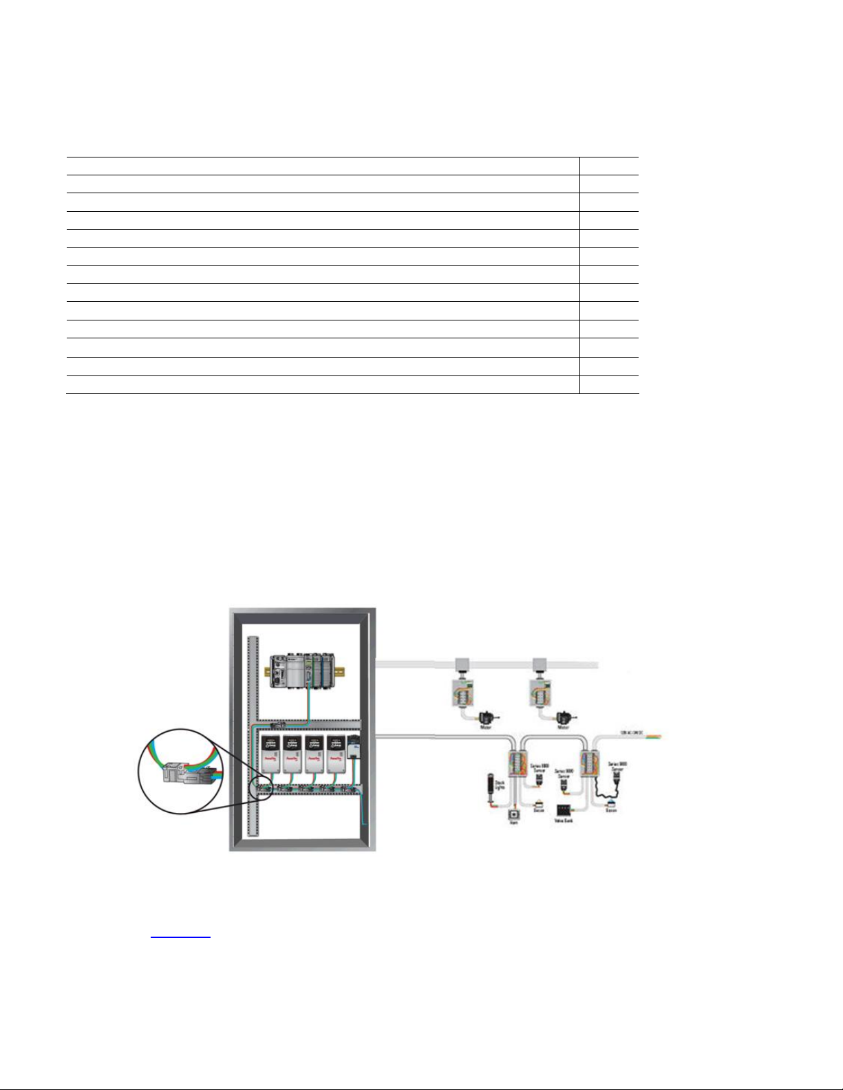
Example Media Configuration
This example illustrates the layout of a drop system configuration.
For detailed wiring information, refer to the Industrial Automation Wiring and Grounding Guidelines,
publication 1770-4.1
.
DNET-QR001A-EN-E – March 2009 3
Page 4

DeviceNet System Quick Reference
Select
Use this table to select the appropriate media for your system. For other media choices, refer to
Chapter 6 in the On-Machine Connectivity Catalog, publication M116-CA001
.
Description Cat. No.
DeviceNet handheld configuration terminal
IP20 flat media
Trunk-line connector, IDC
Drop-line connector, IDC 1485P-K1DL4
Terminating resistor, IDC 1485P-K1TR4
Terminal block, IDC 1485P-K1TLR4
Flat-to-thin round cable converter, IDC 1485P-K1GK4
5-pin open style connector, IDC 1485P-K1G4-Y5
Manual crimp tool 1485A-KCRIMP
ControlLogix DeviceNet scanner module 1756-DNB
CompactLogix DeviceNet scanner module 1769-SDN
4-in/2-out block I/O 120V AC relay DSA 100-DNY41R
193-DNCT
1485-P1W100
1485P-K1TG4
4-in/2-out block I/O 24V DC relay DSA 100-DNY42R
AC/DC DIN-rail mount power supply, DeviceNet 4 A 1606-XLDNET4
E1 DeviceNet module for 193 E1 plus overload relay 193-EDN
PowerFlex DeviceNet communication interface 22-COMM-D
Thin round cable, 50 m (164 ft) roll 1485-P1C50
Terminating resistor 1485A-C2
DNET-QR001A-EN-E – March 2009 4
Page 5
DeviceNet System Quick Reference
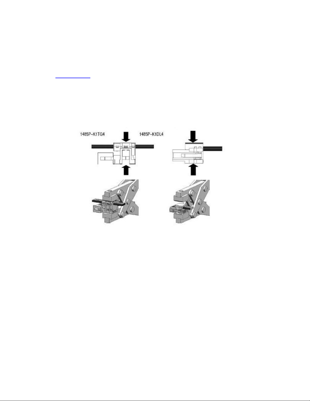
Install
Locate and mount the modules. Follow these steps to crimp the connectors.
For thin round media, refer to the DeviceNet Media Design Installation Guide,
publication DNET-UM072
.
Important:
• Do not crimp the edge of the connector cover.
• Do not crimp at the back of the crimp block.
• Be sure to set the connector in the correct orientation.
1. Set the center of the connector cover (see arrows) in the center of the crimp block of the crimp tool.
2. Crimp the connector until you hear the connector lock into place.
DNET-QR001A-EN-E – March 2009 5
Page 6

DeviceNet System Quick Reference
Configure
193-DNCT Handheld Configuration Device, Revision 2.1 or Later
The 193-DNCT DeviceNet configuration terminal is a handheld device that can configure, program,
retrieve historical data, and monitor DeviceNet components, while directly connected to the network.
Commissioning is made simple with the capability to upload, store, and download complete device
configurations, while online with the network. This tool also aides in troubleshooting by providing
physical layer diagnostics and network bandwidth statistics.
Node Commissioning on Your DeviceNet Network
Once the DeviceNet media and/or cabling system is installed, you need to assign a unique node
number, between 0 and 63, to every device on the DeviceNet network. You can do this by setting the
rotary or dip switches or by using the Node Commission function via software or a handheld device.
Set each device on the network to the same communication rate: 125, 250, 250, or 500 Kbps.
Important:
The factory default for each device is 125 Kbps, set to node number 63 with autobaud
enabled.
DNET-QR001A-EN-E – March 2009 6
Page 7

DeviceNet System Quick Reference
–
Starting the 193-DNCT Terminal
Attach and connect the 193-DNCT terminal to the DeviceNet network. This display appears for
10 seconds.
Baud = Fixed Baud Rate
Auto = Autobaud
AB
DEVICENET HIM
Actual Terminal Node Address
Baud: 125K Auto: 62
Actual Baud Rate
Adrs = Fixed HIM Mac ID
Auto = Auto Addressing
Important:
The DeviceNet configuration terminal is shipped so that when it is placed on a
DeviceNet network for the first time, it automatically sets its baud rate to that of the
traffic on the network. Auto Addressing automation assigns an unused network node
address to the terminal.
After 10 seconds, a Network Who dialog box similar to the one shown below appears with all nodes
and associated devices on the network.
NETWORK WHO Node: 43
0 -- DeviceNet Scanner
2 -- 100-DNY42
5 -- E1 Plus
6 -- Parker Valve
7 -- E1 Plus
8
100-DNY42
Notice that the node number in the upper right corner constantly changes. This shows the node number
that the 193-DNCT terminal is currently scanning during the active network browse it is performing.
If the Network Who dialog box does not appear after 10 seconds, the 193-DNCT terminal is set to
Autobaud Enabled and cannot determine a communication rate as no communication is currently
occurring on the network.
Follow these steps to disable Autobaud.
1. On the 193-DNCT keypad, press ESC
2. Select AutoBaud and press the <Up Arrow>
DNET-QR001A-EN-E – March 2009 7
.
to choose Disable.
Page 8

Follow these steps to set the communication rate to 125 Kbps.
DeviceNet System Quick Reference
1. Press SEL
2. Select BaudRate and press the Up Arrow
3. Press ESC
to advance to BaudRate.
to exit Setup.
to choose 125 Kbps.
Change Node Number 63 to Node Number 1
No entry exists for node 1 in the Network Who dialog box because the device is currently at node 63.
Follow these steps to change to node number from 63 to 1.
1. On the 193-DNCT keypad, press the Down Arrow
Product Name’.
2. Press Enter
3. Press the Down Arrow
4. Press Enter
A dialog box appears with NodeComm selected.
5. Press Enter
to advance to the configuration dialog box.
to select Tools.
.
again.
to scroll through the list and select ‘63 – No
The Node Commissioning dialog box appears with BaudRate selected.
Node Commissioning
------------------------------------- BaudRate: 125K
Address: 63
6. Press SEL to advance to Address and select it.
7. To change the Address, press 1 and then Enter
An Apply Changes dialog box appears.
Tip:
8. Press SEL
After approximately 2 seconds the 193-DNCT terminal re-initializes. In another 10 seconds, the
terminal again displays the Network Who dialog box with node 1 now visible.
You can use the Up Arrow
and then Enter to complete the node commissioning.
and Down Arrow to scroll through the node numbers.
.
DNET-QR001A-EN-E – March 2009 8
Page 9

DeviceNet System Quick Reference
Create the 1756-DNB and 1769-SDN Scanlist by Using AutoScan
The DeviceNet network AutoScan feature allows a scanner to automatically map a network of slave
devices into its scanlist without the use of RSNetWorx for DeviceNet software. This greatly improves
the ease of setting up a DeviceNet network, especially networks comprised of simple devices.
When you enable AutoScan, the 1756-DNB or 1769-SDN scanner module searches for devices on the
network that are not yet mapped. Once a qualifying device is found, the scanner adds the device to its
scanlist and maps its I/O data into a predefined location in the scanner’s I/O memory table. This
location is based on the device’s node address and the mapping size.
AutoScan is not enabled initially. You must enable AutoScan so that devices are automatically added to
the scanlist whenever the scanner module is in Idle mode. The mapping size provides the scanner
module with the number of bytes per node to allocate in the I/O tables. Set the mapping size so that it is
higher than the maximum input or output size of every device on the network. If a device found on the
network has an input or output size larger than the mapping size you set, it will not be added to the
scanlist.
In this example, the mapping size is set to 32 bytes per node. The 193-DNCT terminal configures and
originates AutoScan from a special menu, created specifically for that purpose.
1. Turn the key on the front of the 1756-L63 controller (in slot 2) completely clockwise.
This puts the ControlLogix controller into Program mode, which also puts the scanner module into
Idle mode.
2. In the Network Who dialog box, press the Up Arrow
(0 – 1756-DNB DeviceNet Scanner).
3. Press Enter
4. Press the Down Arrow
5. Press the Down Arrow
This AutoScan Setup dialog box appears.
to go to its configuration dialog box.
to navigate to and select Scanner and press Enter .
to navigate to and select AutoScan and press Enter .
to navigate to and select the first line
AutoScan Setup
AutoScan: Disable
Mapping: 32
Idle Mode
Active Nodes: 0
DNET-QR001A-EN-E – March 2009 9
Page 10

DeviceNet System Quick Reference
6. If AutoScan is selected and set to Disable, press the Up Arrow
7. Press SEL
8. Press SEL
AutoScan begins and the Active Nodes value increments. When the value reaches a node count
of 6, AutoScan is finished and found all 6 nodes on the network.
9. Select AutoScan and press the Up Arrow
10. Press SEL
AutoScan is disabled in the scanner.
11. Press ESC
12. Turn the key on the front of the 1756-L63 controller (in slot 2) completely counter-clockwise.
This puts the ControlLogix controller back into Run mode, which will also put the scanner module
into Run mode, provided that the scanner run bit is set by the logic or data table.
to select Mapping and press 3, 2, and then Enter .
and then Enter to save your changes.
to change to Disable.
twice and then press Enter to save your changes.
three times to return to the Network Who dialog box on the 193-DNCT terminal.
to change to Enable.
View the I/O Mapping Information
Once all of the devices have been added to the scanlist via AutoScan, you can check the I/O data
mapping that was generated by AutoScan. The 193-DNCT terminal can view the input and output data
sizes along with the input and output data mapping assignments for each device.
1. In the Network Who dialog box, press the Up Arrow
(0 – 1756-DNB DeviceNet Scanner).
2. Press Enter
3. Press the Down Arrow to navigate to and select Scanner and press Enter .
4. Press the Down Arrow
This ScanList dialog box appears.
to go to its configuration dialog box.
to navigate to and select ScanList and press Enter .
to navigate to and select the first line
ScanList
0 -- DeviceNet Scanner
2 -- 100-DNY42
5 -- E1 Plus
6 -- Parker Valve
7 -- E1 Plus
8 – 100-DNY42
62 – This DeviceNet HIM
DNET-QR001A-EN-E – March 2009 10
Page 11

DeviceNet System Quick Reference
5. Press the Down Arrow
A dialog box appears with the mapping details of the E1 Plus devices scanlist entry. You can
temporarily disable the 1756-DNB scanner scanlist entry.
6. Press SEL
This entry lets you modify the size of the native data location for the controller you are using.
For example, the Logix-based controllers use a 32 bit Dword for each location in their data table
while some other controllers may use only a 16 bit word. Depending on the native data size of the
controller you are using, you may need to modify this entry, to accurately view the data mapping
assignments for a device in the scanlist.
• The input mapping line displays an 8 to signify an input size of 8 bytes of data going back to
the scanner.
• The next line displays D40:0 --- D41:31 to signify that the data starts at Dword 40, bit 0 of
the input table and continues contiguously to Dword 41, bit 31. Therefore the mapping takes
two complete, 32 bit, Dword locations in the data table. The output mapping line displays a 1
to signify an output size of 1 byte of data coming from the scanner.
• The last line displays D40:0 --- D40:7 to signify that the data starts at Dword 40, bit 0 of the
output table and continues contiguously to Dword 40, bit 7.
7. Press the Down Arrow
to select Mapping.
to navigate to and select 5 – E1 Plus and press Enter .
to change the mapping value.
Notice the effect this change has on the mapping details.
8. Press ESC
four times to return to the Network Who dialog box on the 193-DNCT terminal.
DNET-QR001A-EN-E – March 2009 11
Page 12

DeviceNet System Quick Reference
Example: Configure the E1 Overload
With your fully wired and operational network, there is usually some configuration required for one or
more of the devices, including how the device will behave on the DeviceNet network or how the device
will act as its main function. The 193-DNCT terminal can configure and monitor parameters in the
devices connected to the network. In this example, the 193-DNCT terminal changes the OverLoad
Warning Level parameter in the E1 Plus overload unit.
1. In the Network Who dialog box, press the Down Arrow to navigate to and select 5 – E1 Plus.
2. Press Enter
3. Press the Down Arrow
Device parameters can be viewed by Groups of similar functions or as a Numerical Listing.
4. Press the Down Arrow
The 193-DNCT terminal now displays parameter 1, the Average %FLA parameter.
Important:
to go to the E1 Plus configuration dialog box.
to navigate to and select Params and press Enter .
to navigate to and select Num List and press Enter .
Additional information is provided at the bottom of the display for each parameter
display, including the parameter description (that scrolls continuously), minimum and
maximum values, and if the parameter is read only.
5. Press 1, then 7, and press Enter to display parameter 17 (the OL Warning Level configuration).
The OL Warning Level parameter 17 displays with a value of 80%.
6. Press the SEL
Notice how the configuration value changes to 90% on the display. This value was actually written
to the E1 Plus and has been stored into nonvolatile memory within the device.
, then press 9, 0, and Enter to change the value to 90%.
DNET-QR001A-EN-E – March 2009 12
Page 13

DeviceNet System Quick Reference
Maintain
Diagnostics and Troubleshooting
The 193-DNCT terminal has some diagnostics built in that can be used to troubleshoot a DeviceNet
network. These diagnostics include bus voltages, bandwidth utilization percentage, and CAN error
counts.
1. Press the Down Arrow
2. Press Enter
3. Press the Down Arrow
This dialog box, with similar values, appears on the 193-DNCT terminal.
to select the HIM.
to navigate to Node 62 This DeviceNet HIM.
to navigate to and select the Network group and press Enter .
Baud Rate: 125K
Bus Voltage: 23.90
Bus Voltage Hi: 24.02
Bus Voltage Low: 23.81
Bus % Load: 9.4
Max Bus % Load 16.9
CAN Errors/Sec: 0
The Max Bus % Load and CAN Errors/Sec parameters are not easily measured by other means
and are valuable for troubleshooting the network. The Max Bus % Load parameter shows the
maximum network bandwidth that has ever been used. If this value goes too high, communication
anomalies could occur on the network due to devices being ‘starved’ for bandwidth. The CAN
Errors/Sec parameter is generated if packets are being corrupted on the network, such as due to
electrical noise or a bad device. This value, which should be zero on a healthy network, is a good
barometer of the general health of the DeviceNet packet-delivery mechanism.
DNET-QR001A-EN-E – March 2009 13
Page 14

DeviceNet System Quick Reference
Allen-Bradley, Rockwell Automation, PowerFlex, ControlLogix, CompactLogix, and RSNetWorx for DeviceNet are trademarks of Rockwell Automation, Inc.
Trademarks not belonging to Rockwell Automation are property of their respective companies.
Publication DNET-QR001A-EN-E – March 2009
DNET-QR001A-EN-E – March 2009 14
Copyright©2009 Rockwell Automation, Inc. All rights Reserved. Printed in USA.
 Loading...