

Page 1
DEVICENET SEMINAR
LAB EXERCISES
What’s in This Lab Use these DeviceNet Seminar lab exercises to familiarize yourself with the
DeviceNet network.
ATTENTION: Do not skip ahead! T here is no race to finish t he lab. No prizes
will be awarded for the first people to fin ish. Please take your time and learn
!
For Information On See page
Getting Acquainted with the Lab 2
What’s in the Demo Boxes 2
Describing the Hardware 5
Starting the Software 6
Adding Devices Offline 8
Configuring the DeviceLink Discrete I/O 10
Configuring the FLEX I/O Module 13
Configuring the Scanner 19
Automapping the Network 22
Going Online 28
Building Your Network 31
Monitoring and Configuring the Photoeye Online 32
Monitoring and Configuring the AC Drive Online 38
Configuring the 1747-SDN Scanner Online 42
Using Network Who 47
Using Mini Who 50
Using Node Commissioning 51
Starting RS Logix 500 Software 55
Monitoring Inputs 58
Monitoring Outputs 62
Monitoring the AC Drive Data 64
Monitoring the SMP-3 Overload Relay 66
Monitoring with the Device Failure Table 67
Monitoring a Rung 69
as much as you can.
Publication 1787.6.1 - August 1997
Page 2
2 DeviceNet Seminar Lab Exercises
Windows Conventions Used in This Manual
Getting Acquainted with the Lab
This instruction manual assumes you are familiar with WindowsTM
conventions including minimizing, maximizing, and
closing windows using the button bar at the top right
corner of the window.
• Use the button with the horizontal bar to minimize the window but not
close it.
• Use the button with the square to maximize the window.
• Use the button with the X to close the window.
We’ll go over the following DeviceNetTM features in the lab.
• Hardware overview
• Offline project building and device configuration
• Online project building and device configuration
• Online fault diagnostics and parameter monitoring
• Network Who and Mini Who
• Node commissioning
• SLC processor data monitoring
What’s in the Demo Boxes
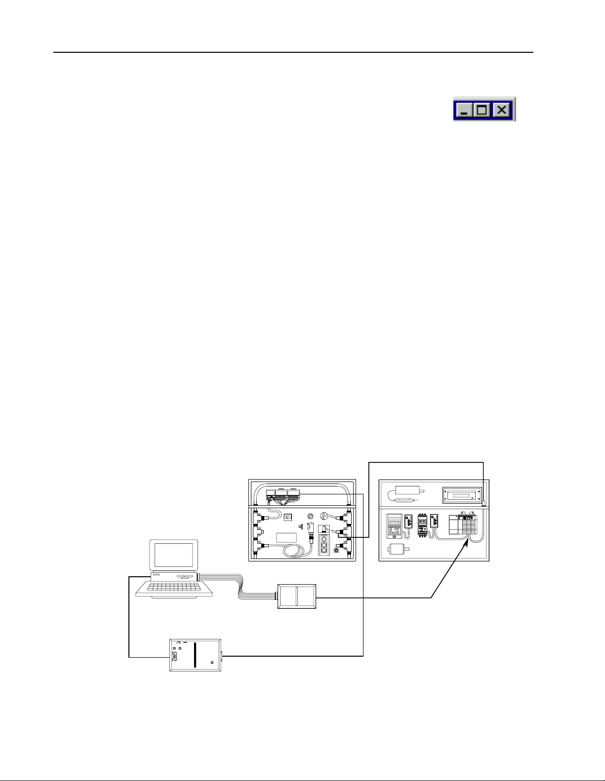
personal computer
RS-232 cable
The following diagram illustrates what’s in the demo boxes.
Device Net drop line
demo box 1
(not included)
RS-232 ribbon cable
DH-485 link
1770-KFD
1747-PIC
personal computer
interface converter
Device Net drop line
1
If you use an SLC 5/04 processor, a Data Highway Plustm link is required.
Note: Demo is supplied with an SLC 5/03 processor.
demo box 2
1
to DH-485 port
on processor
30205-M
1
Publication 1787.6.1 - August 1997
Page 3
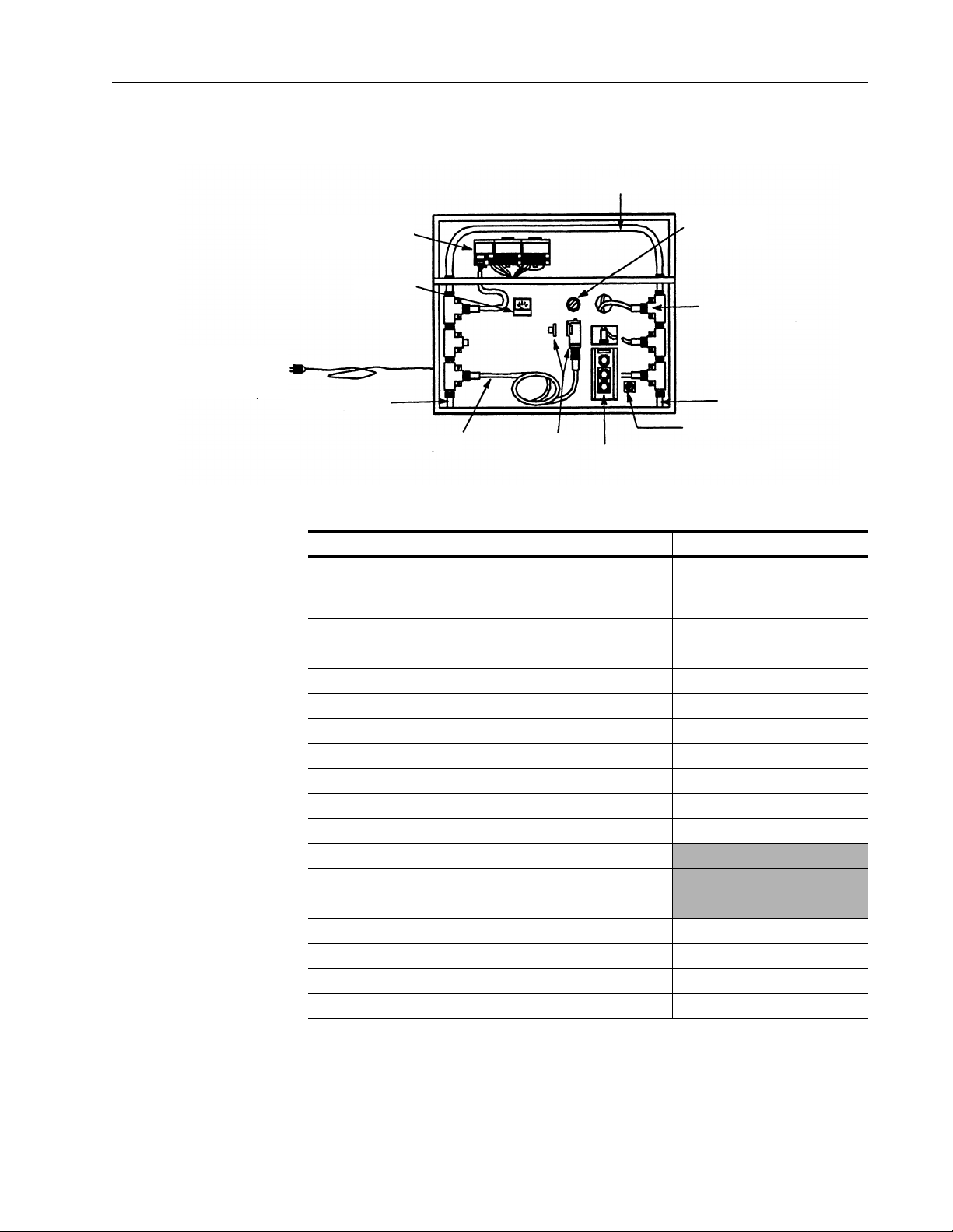
Demo Box 1 Description
DeviceNet Seminar Lab Exercises 3
trunk line
power cord (can be
used with 110V or
220V ac outlet)
FLEX I/O adapter, terminal
bases, and modules
voltmeter
terminating resistor
drop line
photoeye
and reflector
RediSTATION operator interface
4-position
selector switch
power switch
Demo Box 1 includes the following components.
Component (clockwise on drawing) Catalog number
Trunk line
with female field-installable connector
with male field-installable connector
4-position selector switch 800T-N2KF4B
T-Port taps (right keyed) 1485P1N5-MN5R1
Terminating resistor (male) 1485-T1M5
Power switch 800A-H2BW
RediSTATION operator interface 2705-T3DN1A42A
Series 9000 photoeye retroflective 42GNP-9000-QD1
1” reflector 880-N1
Drop line 1485R-P1N5-M5
Terminating resistor (female) 1485-AT1N5
Power cord
Sola SLS-24-024 24V regulated power supply
0-10V dc voltmeter (type 1212 1.5”)
FLEX I/O DeviceNet Adapter 1794-ADN
FLEX I/O Terminal Bases 1794-TB2
FLEX I/O Digital Input Module 1794-IB16
FLEX I/O Analog Output Module 1794-OE4
1485R-P1M5-C
1485-P1T5-N5
1485-P1T5-M5
T-Port tap
terminating resistor
Publication 1787.6.1 - Augu st 1997
Page 4
4 DeviceNet Seminar Lab Exercises
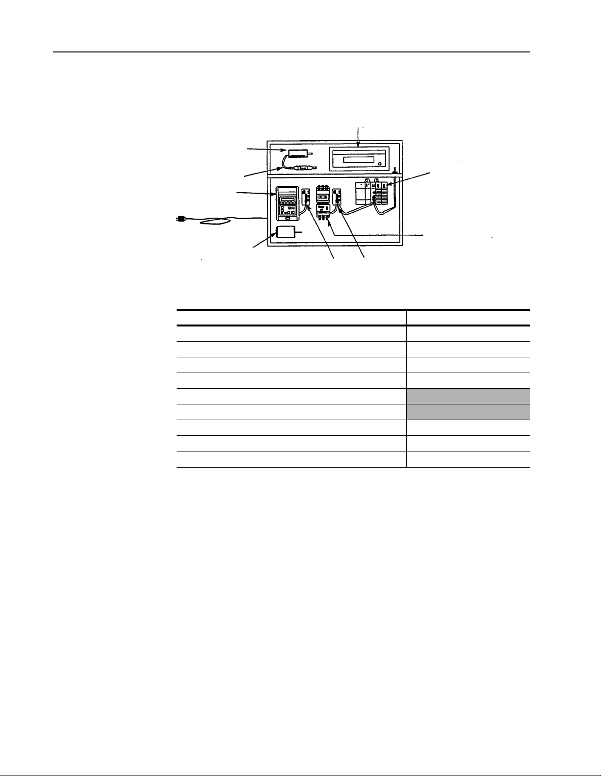
Demo Box 2 Description
limit switch
limit switch
DL10 Dataliner
message display
power cord (can be
used with 110V or
220V ac outlet)
DeviceLink discrete I/O
1305 ac drive
electric motor
1203-GK5 communication module
SLC processor
with DeviceNet scanner
SMP-3 solid-state
overload relay
Demo Box 2 includes the following components.
Component (clockwise on drawing) Catalog number
DL10 Dataliner message display 2706-A11J
SLC processor with DeviceNet scanner 1747-SDN (scanner)
Communication module for power products 1203-GK5 (2 required)
SMP-3 solid-state overload relay Bulletin 193
Parvalux electric motor
Power cord
1305 ac drive 1305
DeviceLink discrete I/O 1485D-A3C3-C
Oiltight limit switch 802T-WSP
Publication 1787.6.1 - August 1997
Page 5
DeviceNet Seminar Lab Exercises 5
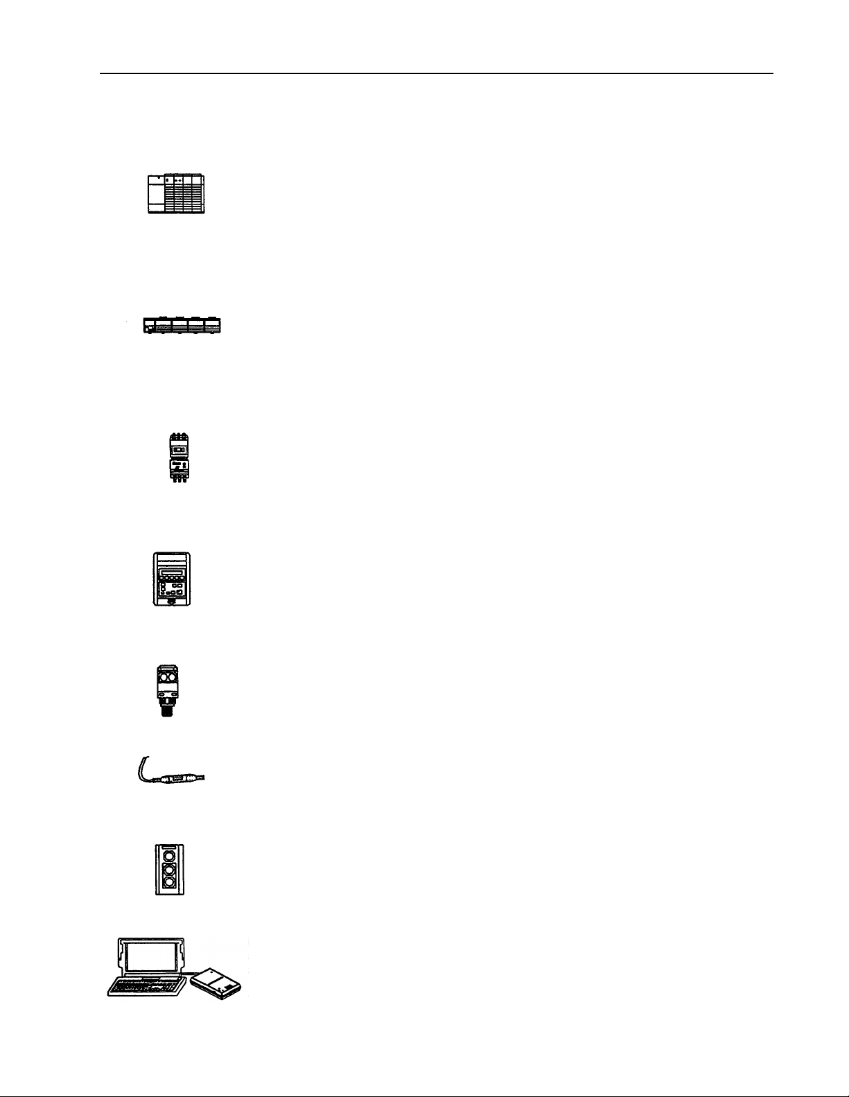
Describing the Hardware
Here are the descriptions and the node numbers of the devices contained in
the demo boxes.
• An I/O chassis with an SLC
Scanner node number = 00
The scanner is the DeviceNet master coordinating all control data to and from all devices
on the DeviceNet network. This DeviceNet data is transferred to and from the SLC 500
processor via M1/MO and discrete I/O transfers. This data is then used in the SLC 500
ladder program to do the actual control logic.
• A 1794-ADN FLEX I/O
input module.
Adapter node number = 02
Analog output channel 0 is connected to a volt meter to easily display the voltage output.
Also a 4-position selector switch is connected to bits 0-3 of the 1794-IB16 discrete input
module.
• An SMP-3
GK5 communication module.
SMP-3 solid state overload relay node number = 03
The SMP-3 solid-state overload rel ay provides solid -state motor overcurren t protection
in addition to ground faul t protection, jam/stall protection, and protecti on against damage
caused by phase loss conditions.
TM
solid-state overload relay connected to the DeviceNet netw ork via a 1203-
TM
500 processor and a 1747-SDN scanner
TM
adapter connected to an an alog output mod ule and a discrete
• A 1305 ac drive connected to the DeviceNet network via a 1203-GK5 communication
module.
1305 ac drive node number = 04
The 1305 ac drive provides d rive stat us and di agnosti c data at t he local panel using t he
part of the drive known as the Human Interface m odule or at a supervisory control station
over DeviceNet5/03.
• A Series 9000 PHOTOSWITCH
Photoeye node number = 07
The Series 9000 ph otoeye is des igned t o wi thstand harsh envir onment s. The sens or for
this lab is retroflective.
• A DeviceLink
TM
discrete I/O connected to a limit switch.
DeviceLink discrete I/O node number = 10
The DeviceLink discrete I/O connects single non-DeviceNet dc source devices to the
DeviceNet network.
• A 2705T RediSTATION
TM
2705T RediSTATION operator interface node number = 15
The RediSTATION operator interface is a pushbutton station that has a start button, a
stop button, and a red pilot light.
• 1787-MGR DeviceNetManager
network via a 1770-KFD interface module.
Software node number = 62
DeviceNet Manager
from multiple vendors and performs network diagno stics and troubleshooting.
software configures software parameters of DeviceNet devices
TM
photoeye.
operator interface.
TM
software, version 3.001 connected to the DeviceNet
Publication 1787.6.1 - Augu st 1997
Page 6
6 DeviceNet Seminar Lab Exercises
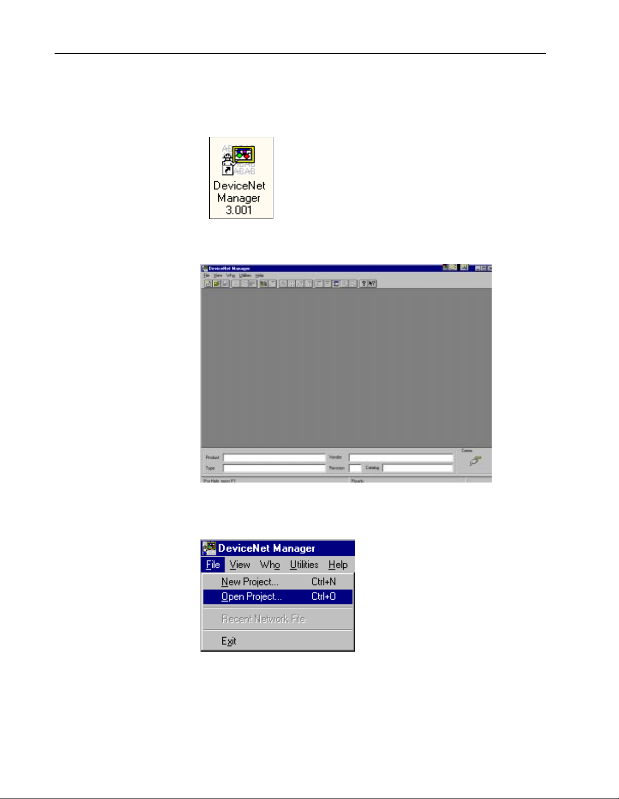
Starting the Software Follow these directions to start the DeviceNet Manager software.
1. Double-click the DeviceNet Manager 3.001 icon that you placed on your
desktop when you installed the software.
Note: If you did not place the icon on your desk top
when you installed the software, you can access
DeviceNet Manager 3.001 from W indows Ex plorer
in the directory c:\DNETMGR, file name
Dnetmgr3.exe.
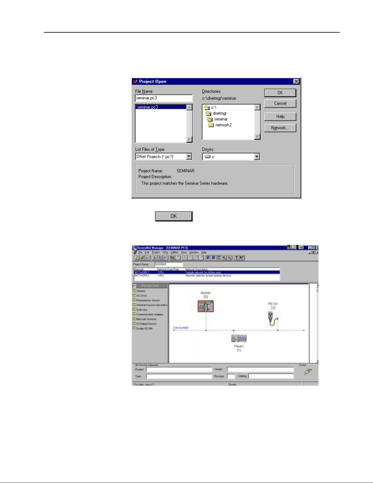
You see this screen.
Publication 1787.6.1 - August 1997
2. From the File menu, choose Open Project...
Page 7
DeviceNet Seminar Lab Exercises 7
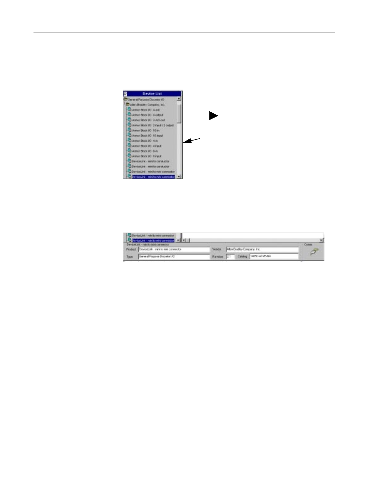
3. Double-click seminar in the Directories box.
You see this screen.
4. Choose
You see the main project screen.
Publication 1787.6.1 - Augu st 1997
Page 8
8 DeviceNet Seminar Lab Exercises
Adding Devices Offline
Follow these directions to add devices to your project offline.
1. In the Device List, double-click General Purpose Discrete I/O.
2. Double-click Allen Bradley Company , Inc.
Tip: You can resize a window by
grabbing the frame edge with the
pointer (the pointer turns to a
double arrow) and dragging the
bar to the right or left.
3. Using the up- and down-arrow keys, scroll down to the second
DeviceLink - mini to mini connector (Revision 2.1). Observe the dialog
box at the bottom of the screen as you scroll through the list to see the
revision number.
4. While holding down the left mouse button (with the device highlighted),
drag the device name from the list to the DeviceNet network in the right
frame. Drop the device anywhere in this frame.
Note: The DeviceNet Manager 3.001 software provides a graphical
interface to build your network. Electronic Data Sheet (EDS) files are
contained in the software. EDS files allow different devices to be added
to a project offline. These same EDS files also allow devices to be
configured both online or offline. EDS files can be quickly and easily
installed into the DeviceNet Manager software for any devices,
regardless of vendor, that will be connected to your DeviceNet network.
Publication 1787.6.1 - August 1997
Page 9
DeviceNet Seminar Lab Exercises 9
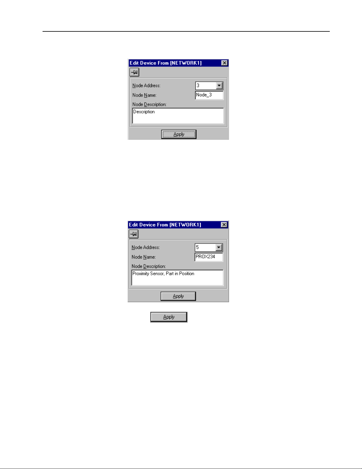
You see this screen.
We will now edit the DeviceLink we just placed.
5. Make the following changes in the Edit Device From dialog box.
A. Scroll down in the Node Address box and choose 5.
B. Type in PROX234 for the Node Name.
C. Type Proximity Sensor, Part in Position for the Node Description.
6. Choose for the changes to take effect.
Publication 1787.6.1 - Augu st 1997
Page 10
10 DeviceNet Seminar Lab Exercises
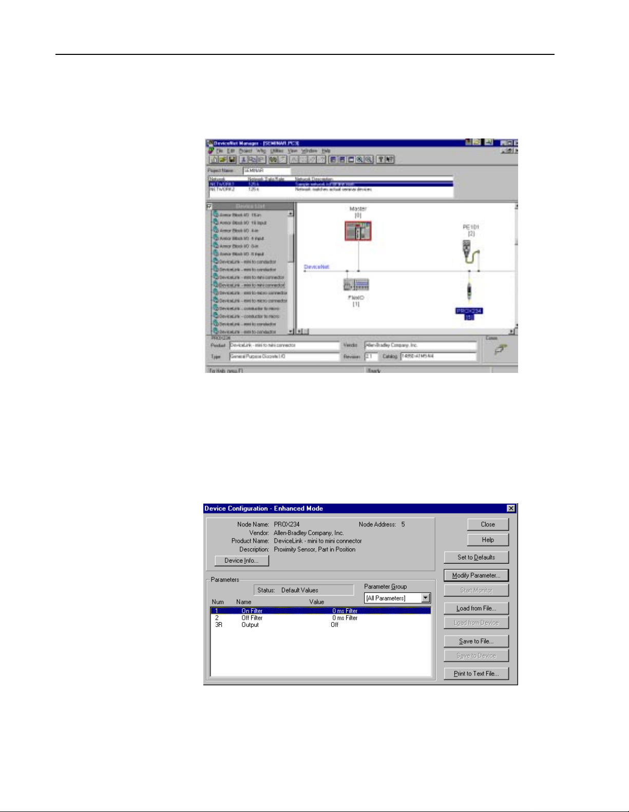
You return to the main project screen.
Note that PROX234 is now added to the graphical DeviceNet network.
Configuring The DeviceLink Discrete I/O
Follow these directions to configure the DeviceLink discrete I/O.
1. Double-click PROX234 (node 5) on the DeviceNet network.
You see this screen.
2. Double-click On Filter.
Publication 1787.6.1 - August 1997
Page 11
DeviceNet Seminar Lab Exercises 11
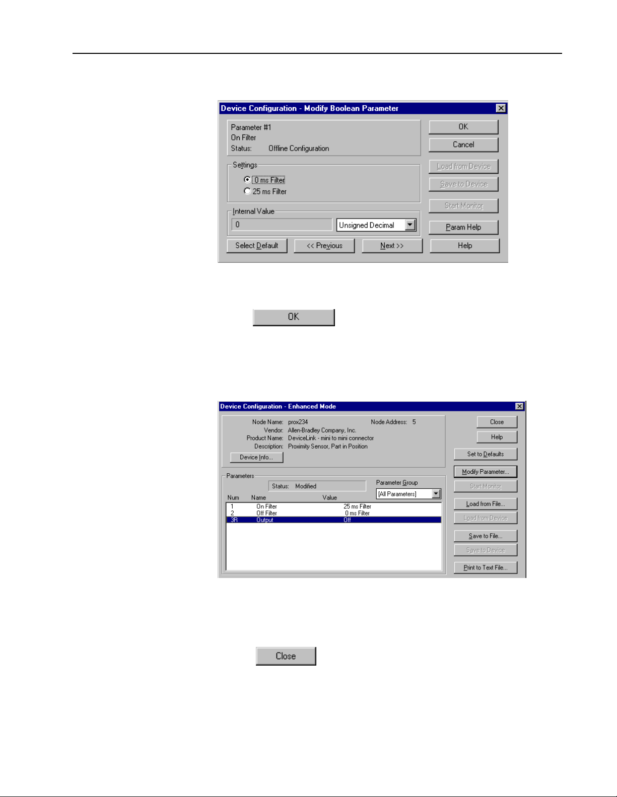
You see this screen.
3. Click the radio button (circle) next to 25 ms Filter.
4. Choose
5. Click Parameter 3R.
You see this screen.
The configuration is changed in the software but has not been saved to
a file or to the DeviceLink discrete I/O itself.
6. Choose
Publication 1787.6.1 - Augu st 1997
Page 12
12 DeviceNet Seminar Lab Exercises
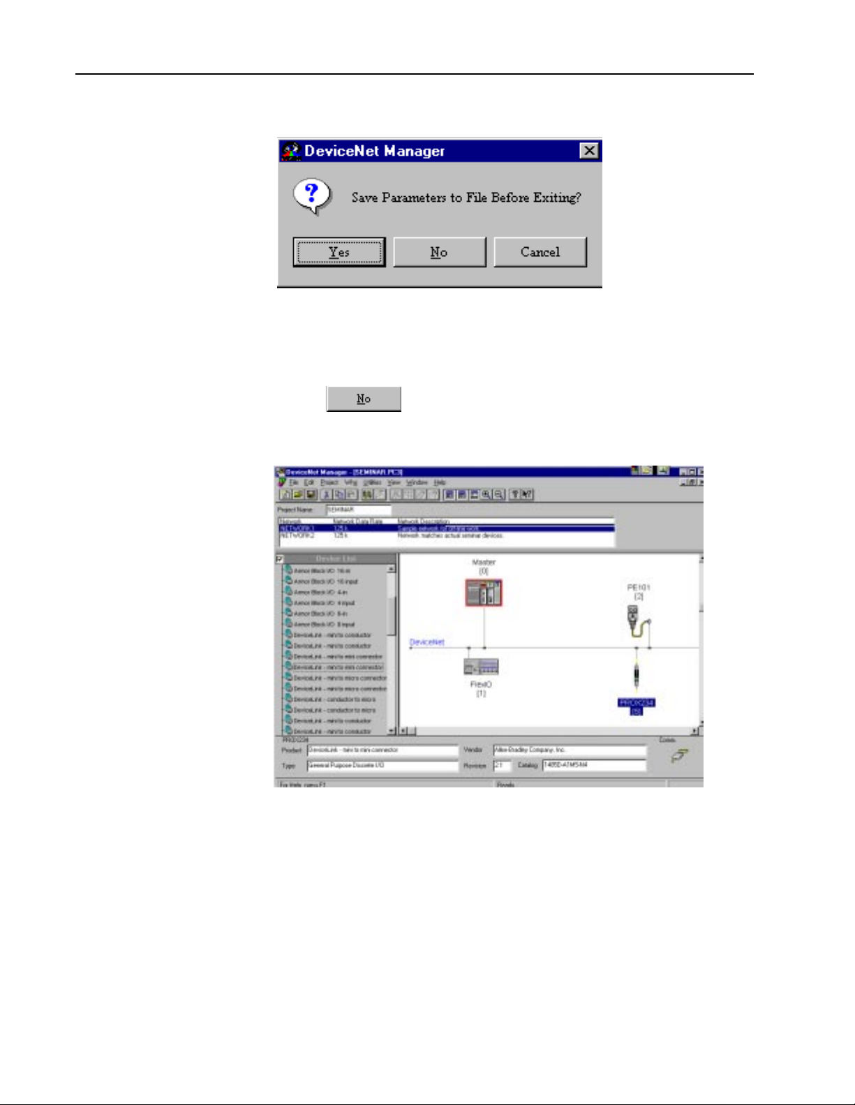
You see this screen.
Note: We will NOT be saving this new configuration now! In offline
mode, the configuration can be stored to a file inside the personal
computer running the software for future recall.
7. Choose
You return to the main project screen.
Publication 1787.6.1 - August 1997
Page 13
DeviceNet Seminar Lab Exercises 13
Configuring the FLEX I/O Module
Follow these directions to configure the FLEX I/O module.
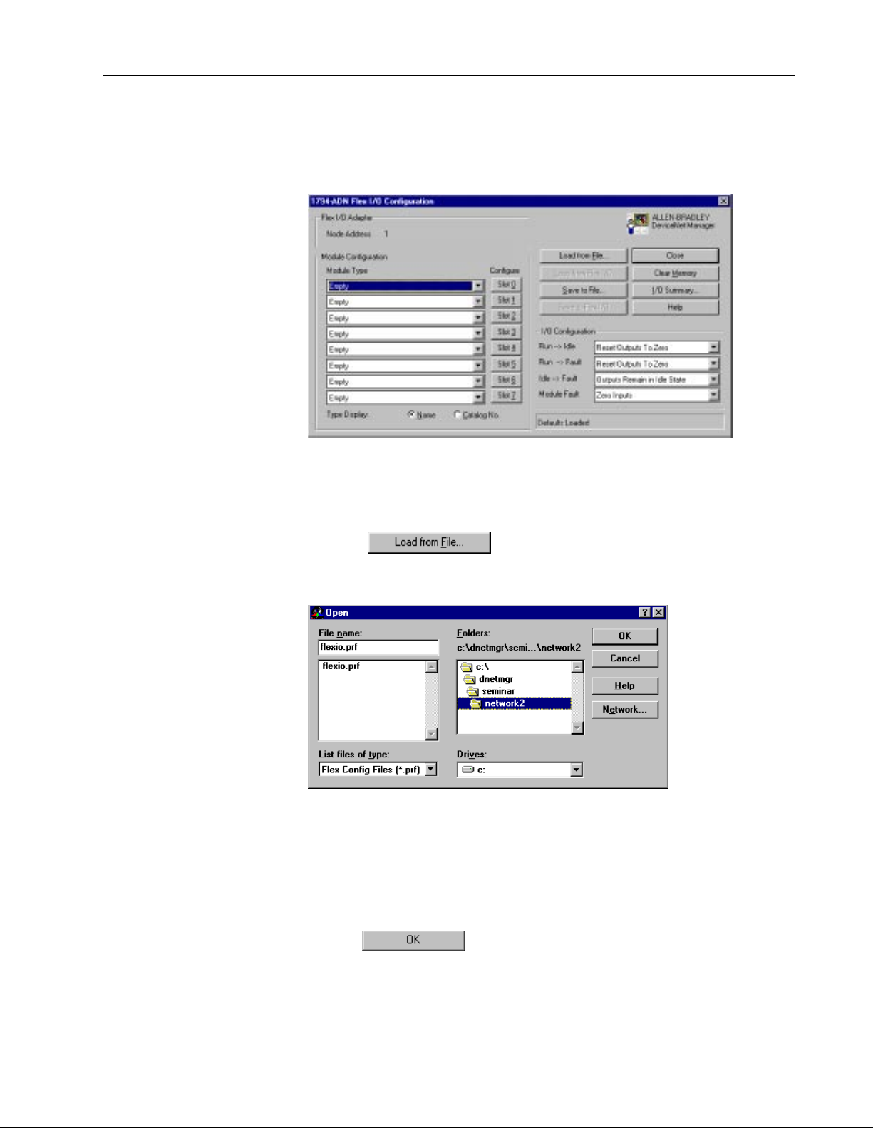
1. Double-click FLEX I/O (node 1) on the DeviceNet network.
You see this screen.
The FLEX I/O configuration screen is a custom application used to
configure the various modules within the FLEX I/O rack.
2. Choose
You see this screen.
3. Double-click the seminar directory.
4. Then double-click the network2 directory.
5. Click once on flexio.prf to highlight it.
6. Choose
Publication 1787.6.1 - Augu st 1997
Page 14
14 DeviceNet Seminar Lab Exercises
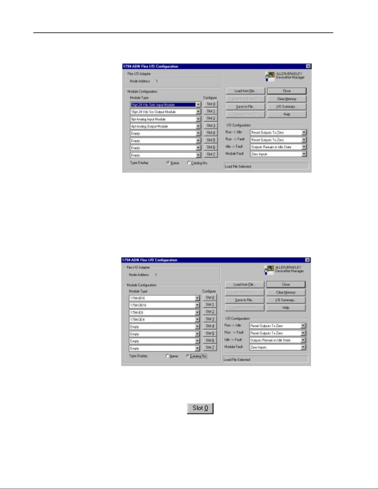
You see this screen.
This file has a previously stored configuration. Four modules displayed
by name are in the module configuration field.
7. To display the module type by Allen-Bradley catalog number, click the
radio button next to Catalog No.
You see this screen.
8. To custom configure the 16-point discrete input module in slot 0
Publication 1787.6.1 - August 1997
(1794-IB16), choose
Page 15
DeviceNet Seminar Lab Exercises 15
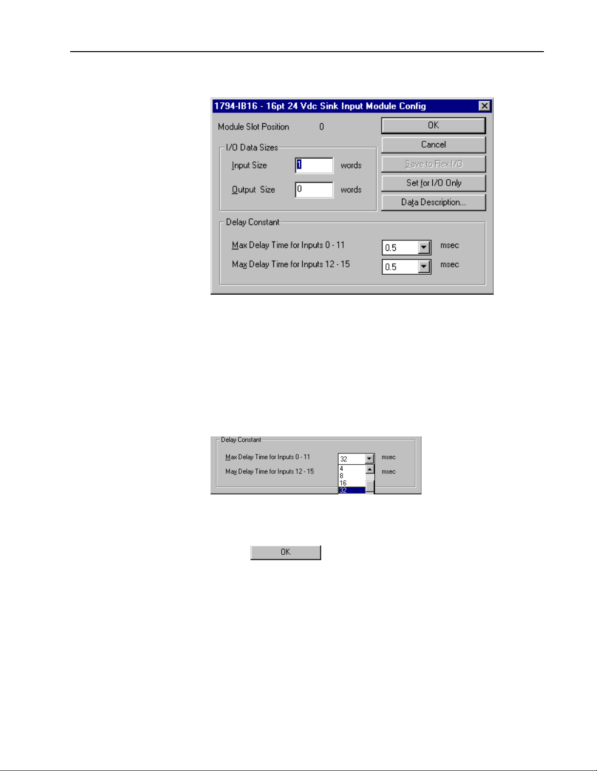
You see this screen.
This screen allows you to enter the amount of input and output used by
the 1794-IB16 along with other module-specific configurations.
Delay constants can be chosen for each of two subgroups of the inputs
(0-11 and 12-15).
9. Click once on the arrow next to the msec box for inputs 0-11 to highlight
your choices.
10. Choose 32 msec.
11. Choose
Publication 1787.6.1 - Augu st 1997
Page 16
16 DeviceNet Seminar Lab Exercises
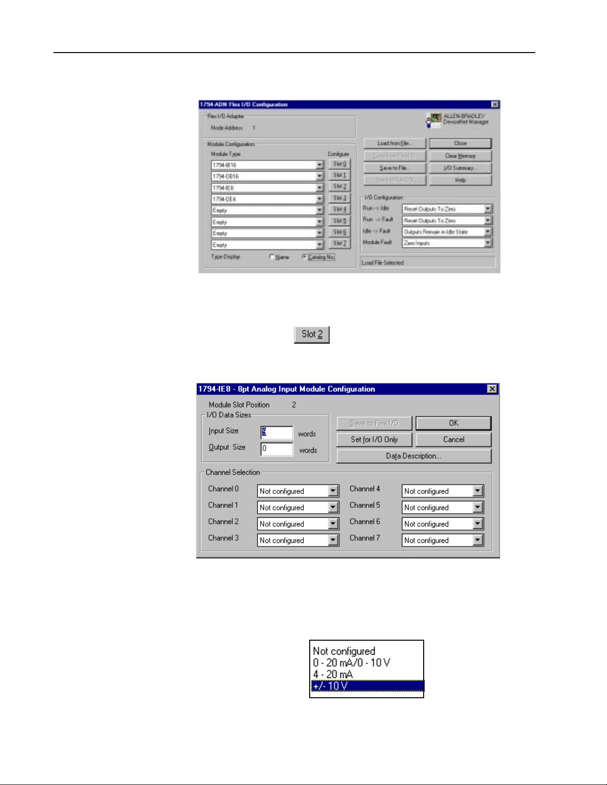
You return to this screen.
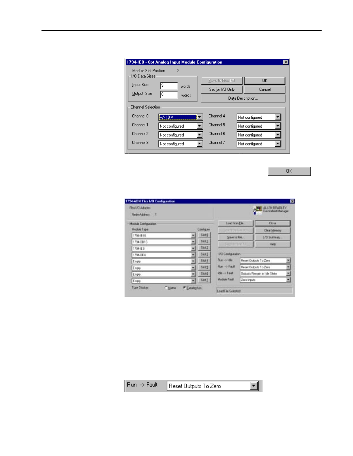
12. To custom configure the 8-channel analog input module in slot 2
(1794-IE8), choose
You see this screen.
Y ou can choose the analog mode configuration for each of the 8 channels
on the module.
13. Click the arrow next to Channel 0.
Publication 1787.6.1 - August 1997
You see these choices.
Page 17
DeviceNet Seminar Lab Exercises 17
14. Click once on +/- 10 V.
15. To exit the 1794-IE8 Configuration screen, choose
You see this screen.
The I/O configuration box determines what will happen to the analog
and discrete outputs in the FLEX I/O rack when there is a fault or idle
condition on the DeviceNet network.
An example of idle condition is when the PLC processor is placed in
program mode. An example of fault condition is a broken communication
line.
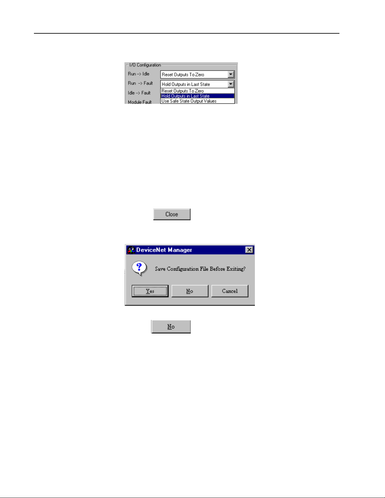
16. In the I/O Configuration box, click once on the arrow next to
Publication 1787.6.1 - Augu st 1997
Page 18
18 DeviceNet Seminar Lab Exercises
17. Click once on Hold Outputs in Last State to select it.
The 1794-ADN will now default to Hold Outputs in Last State if a fault
is detected while the 1794-ADN is in Run mode.
Note: W e will NOT be saving this new configuration now! In future uses,
once all modules are configured, the configuration needs to be saved.
You would choose Yes to save the configuration to a file within this
project. When online, the configuration can be both read and saved
directly to the 1794-ADN adapter using the Load from Device, Apply
Configuration and Save to Device buttons.
18. Choose to exit the FLEX I/O configuration screen.
You see this screen.
19. Choose
Publication 1787.6.1 - August 1997
Page 19
DeviceNet Seminar Lab Exercises 19
You return to the main project screen.
Configuring the Scanner
Follow these directions to configure the 1747-SDN scanner.
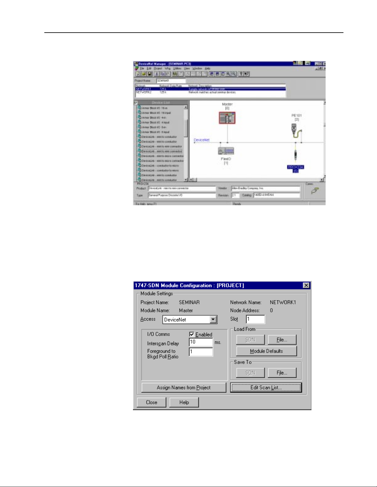
1. Double-click the Master (node 0) on the DeviceNet network.
You see this screen.
This screen allows you to configure the 1747-SDN scanner’s operating
parameters along with entering the scan list of what devices will be
scanned on the network.
Publication 1787.6.1 - Augu st 1997
Page 20
20 DeviceNet Seminar Lab Exercises
Notice that the project name is SEMINAR and the network name is
NETWORK1.
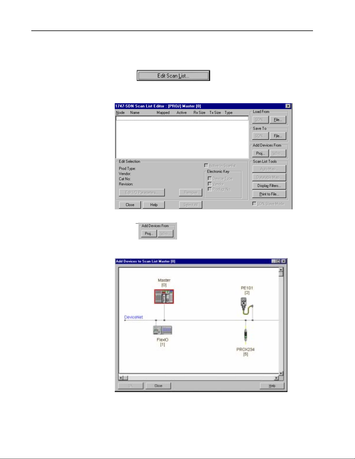
2. Choose
You see this screen.
3. Choose
You see the main project screen.
Publication 1787.6.1 - August 1997
We will now build the scan list by dragging and dropping devices onto
the Master device (node 0).
Page 21
DeviceNet Seminar Lab Exercises 21
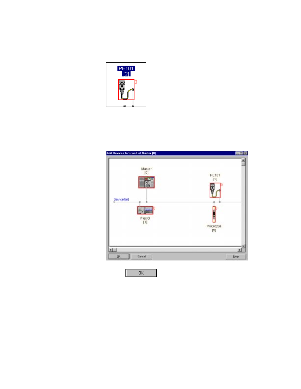
4. Click PE101 (node 2) once to highlight it. While holding down the left
mouse button, drag PE101 over to the master and drop it. Notice that
PE101 now has a red square around it with a “0” next to the red square.
5. Repeat this step to add the other two devices on the DeviceNet network
to the Master.
When all devices are added to the Master you see this screen.
6. Choose
Publication 1787.6.1 - Augu st 1997
Page 22
22 DeviceNet Seminar Lab Exercises
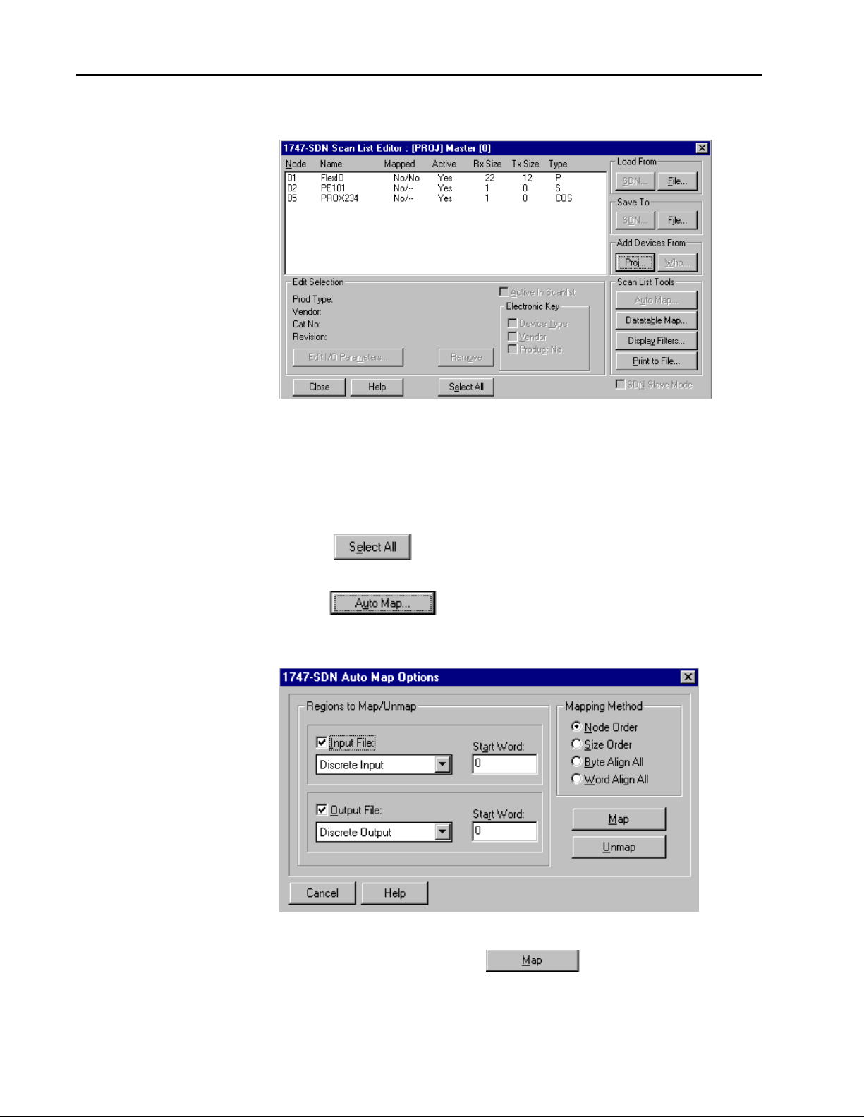
You see this screen.
Automapping the Network
Follow these directions to automap your DeviceNet devices’ data into the
SLC-500 input and output I/O memory.
1. Choose to highlight all of the devices.
2. Choose
You see this screen.
Publication 1787.6.1 - August 1997
3. To start automapping, choose
Page 23

DeviceNet Seminar Lab Exercises 23
The software maps the devices and returns you to this screen.
Notice that all three slave devices in the list have “Yes” in the active
column as they are now active in the scan list and will communicate to
the 1747-SDN scanner on the network.
Also notice the “Y es” in the Mapped column, which is showing that data
is currently mapped to and/or from the SLC-500. The “Yes” in the left
column means that data is mapped from the device to the SLC-500. The
“Yes” in the right column means that the data is mapped to the device
from the SLC-500.
Observe that the FLEX I/O is mapped both from the device to the SLC500 and is also mapped to the device from the SLC-500.
4. T o view the actual areas inside the SLC-500 where the device data will be
transferred to and from, choose
Publication 1787.6.1 - Augu st 1997
Page 24

24 DeviceNet Seminar Lab Exercises
You see this screen.
Notice that node 1 occupies words 1 through 11 of the discrete input area.
This is the input data from the FLEX I/O node. You may need to scroll
down to see I:1.11 on the screen.
Notice that word I:1.0 is reserved for the module status register of the
1747-SDN (denoted above by the letter R).
5. Click the radio button next to Output in the Data Map section.
You see this screen.
Publication 1787.6.1 - August 1997
Notice that node 1 occupies words 1 through 6 of the discrete output
area. This area is for the output data to the FLEX I/O rack. Word 0 is
reserved for the module command register.
Page 25

DeviceNet Seminar Lab Exercises 25
6. Return to Input by clicking on the radio button next to Input in the Data
map section.
7. In the Device Select box, click once on the arrow to display your choices.
8. Choose PROX234 (node 5).
You see this screen.
Notice that nodes 2 and 5 share word 12 of the discrete input area where
the input data from these devices will be put.
9. Click the radio button next to Data Entry in the Display Mode section.
Y ou can manually remap data to anywhere in the SLC-500 memory space
allocated to the 1747-SDN.
Publication 1787.6.1 - Augu st 1997
Page 26

26 DeviceNet Seminar Lab Exercises
We will now direct the DeviceLink discrete I/O from the discrete input
file into the M1 file area.
10. In the Map Data To box, click the arrow to display your choices.
A. Choose M File.
B. In that same row, change Word 12 in the M1:1 box to 0.
C. Change Bit 8 to 0.
11. Choose
Scroll up to see this screen.
Publication 1787.6.1 - August 1997
12. Choose
You return to this screen.
Page 27

DeviceNet Seminar Lab Exercises 27
13. Choose
You see this screen.
Note: W e will NOT be saving this new configuration now! In future uses,
once all of the data is mapped, the configuration needs to be saved. You
would choose Yes to save the configuration to a file within this project.
When online, the configuration can be both read and saved directly to
the 1747-SDN scanner using the Save To and Load From buttons.
14. Choose
You return to this screen.
15. Choose
Publication 1787.6.1 - Augu st 1997
Page 28

28 DeviceNet Seminar Lab Exercises
You return to the main project screen.
Going Online Follow these directions to go online with the DeviceNet network.
Note: You should be at the main project screen with SEMINAR.PC3 at the
top of the screen.
1. Click once on Network2.
You see this screen.
Publication 1787.6.1 - August 1997
Page 29

DeviceNet Seminar Lab Exercises 29
2. From the Utilities menu, choose Setup Online Connection...
You see this screen.
3. Choose
Publication 1787.6.1 - Augu st 1997
Page 30

30 DeviceNet Seminar Lab Exercises
You see this screen.
Important: Your values should match those seen on this screen.
4. Choose
!
ATTENTION: In future uses, you need to make sure that all
devices are set to the proper data rate. Attempting to go online at the wrong data rate may cause some or all devices on
the network to fail.
Publication 1787.6.1 - August 1997
Page 31
DeviceNet Seminar Lab Exercises 31
Building Your Network
Follow these directions to have the software build your network once you
are online.
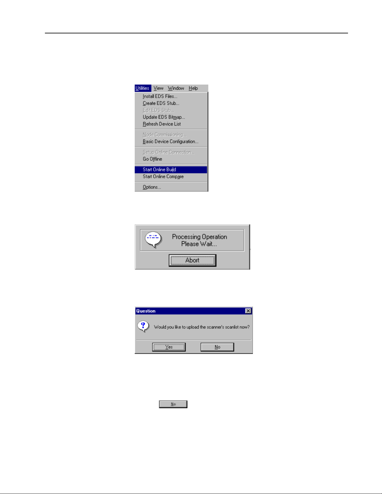
1. From the Utilities menu, choose Start Online Build...
You see this message while Online Build is occurring.
When the Online Build is finished, you see this screen.
At this time it is not necessary to upload the 1747-SDN scan list over the
network. The scan list will be loaded from a file later in the exercises.
2. Choose
Publication 1787.6.1 - Augu st 1997
Page 32

32 DeviceNet Seminar Lab Exercises
You see the device list screen.
Configuring the Photoeye Online
We will now monitor and configure a few of these devices online.
Follow these directions to configure the photoeye online.
1. Rotate the selector switch at the top of the demo box so that an amber
2 is illuminated on the front of the 1794-IB16 FLEX I/O module.
2. In the Device List, double-click on node_7, the Series 9000 Retroflective
photoeye.
Publication 1787.6.1 - August 1997
Page 33

You see this screen.
3. Double-click Parameter 2R.
DeviceNet Seminar Lab Exercises 33
You see this screen.
Notice that the green margin status indicator on the sensor is lit as the
reflector is correctly aligned with the sensor.
4. Choose
5. Put your hand between the reflector and the photoeye.
You will see that the setting on the software changes from On to Off.
Also notice that the red light on the RediSTATION operator interface
module goes on.
Publication 1787.6.1 - Augu st 1997
Page 34

34 DeviceNet Seminar Lab Exercises
6. Remove your hand from between the reflector and the photoeye.
You will see that the setting on the software changes back from Off to
On and the red light on the RediSTATION operator interface module
goes off.
The RediSTATION operator interface’s light is controlled from the
SLC-500 processor using the status bit from the photoeye as an input
into the 1747-SDN scanner.
7. Choose Stop Monitor.
8. Choose
You return to this screen.
Publication 1787.6.1 - August 1997
Page 35

DeviceNet Seminar Lab Exercises 35
Testing the Low-Margin Capability
Low margin is determined by the sensor when it is not receiving enough light
for optimum operation. The amber status indicator is lit but the green margin
status indicator is not when in low margin mode.
1. Double-click Parameter 3R.
Notice that the operating margin of the photoeye is OK.
2. Choose
3. Swivel the reflector out of position until the outermost green margin sta tus
indicator on the photoeye goes off and the amber indicator is still on. The
parameter setting will show low margin.
Notice the red light on the Re diSTATION operator interface blinks and
the DL10 Dataliner display show a PHOTO OUT OF M ARGIN message.
This message is made available to the SLC-500 processor for control
purposes.
Note: While low on margin, the photoeye will still operate correctly. It
is just alerting you that something is wrong. Maybe the lens is getting
dirty or the reflector has moved.
To demonstrate this feature while the reflector is still swiveled out of
position (low on margin), place your hand between the reflector and the
photoeye. The RediSTATION operator interface’s light goes on.
4. Reposition the reflector so all three status indictors on the photoeye are
on solid.
5. Choose Stop Monitor.
6. Choose
Publication 1787.6.1 - Augu st 1997
Page 36

36 DeviceNet Seminar Lab Exercises
You return to this screen.
7. Double-click Parameter 1.
You see this screen.
Publication 1787.6.1 - August 1997
Notice the current Operate Mode is Light Operate.
8. Click the radio button next to Dark Operate.
9. Choose
Notice that the RediST A TION operator interface’s red light goes on. The
light will turn off if you put your hand between the photoeye and the
reflector. This behavior is opposite of what it was before because you
inverted the operate mode of the photoeye over the network.
Page 37

DeviceNet Seminar Lab Exercises 37
10. To return operation to the original mode, click the radio button next to
Light Operate.
11. Choose
12. Choose
Important: All three lights on the photoeye should be illuminated and
the RediST ATION operator interface’s red light of f. Go back to step 7 if
this is not true.
13. To exit the Device Configuration screen, choose
You return to this screen.
In summary , we have just shown you control status (on/off), diagnostics
(low margin), and configuration (light/dark operate), all from one device
over the DeviceNet network.
Publication 1787.6.1 - Augu st 1997
Page 38

38 DeviceNet Seminar Lab Exercises
Monitoring and Configuring the AC Drive Online
Follow these directions to configure the ac drive online.
1. Rotate the selector switch at the top of the demo box so that an amber
0 is illuminated on the front of the 1794-IB16 FLEX I/O module.
2. Double-click Node 4, the ac drive via the 1203-GK5 module.
You see this screen in approximately 10 seconds.
Important: If you do not see this screen, ask your instructor for
assistance.
3. Double-click Parameter 1R.
You see this screen.
Publication 1787.6.1 - August 1997
Notice the output voltage is 0.
Page 39

DeviceNet Seminar Lab Exercises 39
4. Choose
5. Press the green Start button on the front of the RediSTATION operator
interface.
Notice that the output voltage displays a voltage around 56 V . Also notice
that the 1305 ac drive displays At Speed and 15.00 Hz.
Each time the green Start button is pre ssed, the voltage will i ncrease or
decrease by 56 V until it finally wraps around to 56 V again.
Each time you press the green Start button, the speed display on the drive
will also increase by 15.00 Hz until it reaches 60 Hz where it will wrap
back around to 15.00 Hz. Pressing the red Stop button causes the speed
and output voltage to go to 0.
Notice that the drive reverses direction the next time you press the Start
button. After you press the Stop button, each time you press the Start
button the drive will again change direction.
6. Choose Stop Monitor.
7. Choose
You return to this screen.
8. Double-click Parameter 7 “Accel Time 1”.
Publication 1787.6.1 - Augu st 1997
Page 40

40 DeviceNet Seminar Lab Exercises
9. Change the accel time to 20s by typing 20 in the value field.
10. Choose
11. Press the RediSTATION operator interface’s red Stop button.
Now look at the front of the drive.
12. Press the RediSTATION operator interface’s green Start button.
Notice that it took longer to reach 15.00 Hz due to the new accel time.
13. Press the RediSTATION operator interface’s red Stop button.
14. Important: Restore the accel time to 5s by typing 5 in the value field.
15. Choose
The original accel time has been restored.
This exercise showed our ability to monitor and configure the ac drive
over the network with the software. It also showed our ability to start,
stop, and change the speed of the drive from the SLC-500 processor over
the DeviceNet network.
16. To exit the Device Configuration screen, choose
Publication 1787.6.1 - August 1997
Page 41

You see this screen.
17.Choose
DeviceNet Seminar Lab Exercises 41
You see this screen.
Publication 1787.6.1 - Augu st 1997
Page 42

42 DeviceNet Seminar Lab Exercises
Configuring the 1747-SDN Scanner Online
Follow these directions to configure the scanner online.
1. Double-click Node_ 0, the 1747-SDN scanner.
You see this screen.
2. Choose
You see this screen.
3. Choose Load From File.
4. Click once on seminar.sl4 to highlight it.
Publication 1787.6.1 - August 1997
Page 43

You see this screen.
5. Choose
You see this screen.
DeviceNet Seminar Lab Exercises 43
6. Choose
Publication 1787.6.1 - Augu st 1997
Page 44

44 DeviceNet Seminar Lab Exercises
You see this screen.
By using the device select field, you can view the mapping of each device
into the data table inside the SLC-500 processor.
Note: The RediSTA TION, photoeye, and DeviceLink are all sharing the
same data field. This shows the versatility of the DeviceNet Manager
software for mapping device data. The scan list is the same as what is
actually loaded in the 1747-SDN of your seminar. These bits will be
monitored later in the SLC-500 using RSLogixTM 500 programming
software.
7. To exit the Scan List Editor screen, choose
You see this screen.
Publication 1787.6.1 - August 1997
Page 45

8. Choose
You see this screen.
9. Choose
You see this warning screen.
DeviceNet Seminar Lab Exercises 45
10. Choose
You return to this screen.
Publication 1787.6.1 - Augu st 1997
Page 46

46 DeviceNet Seminar Lab Exercises
11. Choose
You return to the project screen.
12. Close the project window by clicking the button with an X i n the upper
right corner of the project window.
Important: Click the lower X, so as to close the project but not
DeviceNet Manager software.
You see this screen.
13. Choose
Publication 1787.6.1 - August 1997
Page 47

DeviceNet Seminar Lab Exercises 47
You return to the main DeviceNet Manager screen.
Note that you are still online.
Using Network Who Network Who provides you with a summary of the node address,
manufacturer of the device, device type, product name and serial number for
each device on the network, plus the total number of devices identified.
Important: You must be online to select Network Who.
1. From the Who menu, choose Network Who.
This screen appears while Network Who operates.
Publication 1787.6.1 - Augu st 1997
Page 48

48 DeviceNet Seminar Lab Exercises
When it is finished scanning the network, you see this screen.
2. Click once on Node_ 0 to highlight it.
3. Choose
You see this screen.
Publication 1787.6.1 - August 1997
Notice the details that can be accessed directly from the devices, such as
firmware revisions and serial numbers.
Page 49

DeviceNet Seminar Lab Exercises 49
4. To scroll through the list, choose or
5. Once you have finished, choose
You return to this screen.
You could also configure a device from Network Who
by choosing
This method is the same as double clicking an icon on the DeviceNet
network as we did earlier in this seminar in the Configuring Devices
Offline section.
6. Choose
Publication 1787.6.1 - Augu st 1997
Page 50

50 DeviceNet Seminar Lab Exercises
You see this screen.
7. Choose
You return to the main DeviceNet Manager screen.
Using Mini Who Mini Who is a quick way to determine devices on the network by node
number and the total number of devices found on the network.
Important: You must be online to select Mini Who.
1. From the Who menu, choose Mini Who.
Publication 1787.6.1 - August 1997
Page 51

DeviceNet Seminar Lab Exercises 51
You see this screen.
Y ou can wait for Mini Who to finish scanning the network, which doesn’ t
take long, or you can choose
Using Node Commissioning
2. Choose
You return to this screen.
Node Commissioning allows you to change the node address and data rate
of individual devices. This is normally done when a network is initially
assembled. Devices out of the box will have node 63 and 125 k baud as
defaults.
Important: You cannot be within a project to commission nodes.
Publication 1787.6.1 - Augu st 1997
Page 52

52 DeviceNet Seminar Lab Exercises
1. From the Utilities menu, choose Node Commissioning...
You see this screen.
2. In the Current Device Settings box, scroll the list and choose node 7 (the
photoeye).
Publication 1787.6.1 - August 1997
Page 53

DeviceNet Seminar Lab Exercises 53
3. In the New Device Settings box, scroll the list and choose node 55.
4. Choose
Notice that the RediSTATION operator interface’s red light starts
blinking, the DL10 Dataliner display shows a PHOTO OFF
DEVICENET message, and the scanner display alternatively blinks
between 72 and 07. Also, the green status indicator on the photoeye
should be blinking green.
The reason for the above warning messages is that the 1747-SDN scanner
module is expecting a slave device (the photoeye) at node address 7. By
changing the node address to 55, node 7 has “disappeared”. This
disappearance sets a fault bit in the scanner’s memory , which can be read
by the SLC processor to display fault diagnostics, such as flashing a red
light or displaying a text message. Also, the photoeye with its new node
address no longer has a master to communicate with thus causing it to
flash its green communication status indicator.
Now let’s return the photoeye to node address 7.
Publication 1787.6.1 - Augu st 1997
Page 54

54 DeviceNet Seminar Lab Exercises
5. In the Current Device Settings box, scroll the list and choose node 55.
6. In the New Device Settings box, scroll the list and choose node 7.
Publication 1787.6.1 - August 1997
7. Choose
Notice that the RediSTATION operator interface’s red light stops
blinking, the DL10 Dataliner display returns to the normal message, the
scanner displays 00, and the photoeye’ s communications status indicator
turns solid green.
8. Choose
Page 55

DeviceNet Seminar Lab Exercises 55
You return to the main DeviceNet Manager screen.
Starting RSLogix 500 Software
Minimize the software by clicking the button wit h the horizontal ba r in
the upper right corner of the window.
Important: Do not close the software. Only minimize it.
The next section of the lab uses RSLogix 500 programming software.
1. Double-click the RSLogix 500 icon on your desktop to start the program.
Note: If you do not have the RSLogix 500 icon on your desktop, you can
access it from Windows Explorer in the directory c:\RSI\logix500, file
name RS500.exe.
Publication 1787.6.1 - Augu st 1997
Page 56

56 DeviceNet Seminar Lab Exercises
You see this screen.
2. From the Comms menu, choose Go Online.
You see this screen.
Publication 1787.6.1 - August 1997
Page 57

DeviceNet Seminar Lab Exercises 57
3. From the navigation window in the left frame, scroll down from Project
to Program Files and choose LAD 155 by double clicking.
You see this screen in the right frame. You see the rungs of ladder logic.
Monitoring Inputs Follow these directions to monitor the inputs using RSLogix 500 software.
1. From Data Files, choose I1 by double clicking.
Publication 1787.6.1 - Augu st 1997
Page 58

58 DeviceNet Seminar Lab Exercises
You see this screen.
Publication 1787.6.1 - August 1997
Notice that Word I:1.1 format (shown on page 44 and again here for
reference), is shared by nodes 7, 10 and 15.
Page 59

DeviceNet Seminar Lab Exercises 59
2. Rotate the selector switch completely counter-clockwise until an amber
0 is illuminated on the 1794-IB16.
3. Press and hold the Start button until you see that data location I:1.1, bit
9 changes to a 1.
4. Release the Start button.
5. Press and hold the Stop button until you see that data location I:1.1, bit
8 changes to a 1.
6. Release the Stop button.
7. Press and release the Start button.
Notice the red light on the RediSTATION operator interface goes on.
8. Carefully unscrew the red lens and remove the light bulb by pressing down
Publication 1787.6.1 - Augu st 1997
Page 60

60 DeviceNet Seminar Lab Exercises
gently and turning the light bulb counter-clockwise.
Notice in data location I:1.1 that bit 12 changes to a 1.
9. Replace the light bulb by gently pressing it into its socket and turning it
clockwise. Bit I1:1/12 goes to a 0.
10. Replace the red lens.
Note: This diagnostic only works if the RediSTATION light is on (the
Start button has been pushed).
11. Press the RediSTATION operator interface’s Stop button.
12. Move the lever up and down on the limit switch connected to the
DeviceLink discrete I/O.
Notice in I:1.1 that bit 7 goes from a 0 to a 1 each time you move the
lever connected to the DeviceLink discrete I/O.
Also notice in I:1.1 that bit 14 goes from a 1 to a 0 each time you put
your hand between the photoeye and the reflector. Bit 15 of I:1.1 goes
from a 0 to a 1 when the photoeye is low on margin.
13. T o demonstrate low on margin, swivel the reflector until the green margin
status indicator on the photoeye goes off and the amber indicator is on.
Notice that the red light on the RediSTATION operator interface blinks
and the DL10 Dataliner displays a PHOTO OUT OF MARGIN message.
(Bits 14 & 15 are 1). This message is made available to the SLC-500
processor for control purposes.
14. T o verify this operation, put your hand in front of the photoeye and notice
that the RediSTATION operator interface’s light goes solid.
Publication 1787.6.1 - August 1997
15. Swivel the reflector back so that it is not in low m ar gin. All three LEDs
should be on.
Page 61

DeviceNet Seminar Lab Exercises 61
Notice as you rotate the selector switch clockwise and counter-clockwise,
one of bits 0 through 3 in data location I:1.4 goes to a 1 depending on
which position the switch is in.
16. Close the Data File by clicking the button with an X in the upper right
corner of the Data File window.
You return to this screen.
Monitoring Outputs Follow these directions to monitor the outputs using RSLogix 500 software.
Publication 1787.6.1 - Augu st 1997
Page 62

62 DeviceNet Seminar Lab Exercises
1. From Data Files, choose O0 by double clicking.
You see this screen.
Publication 1787.6.1 - August 1997
2. Rotate the selector switch counter-clockwise until an amber 0 is
illuminated on the 1794-IB16.
3. Press the RediSTATION operator interface’s Start button.
Notice in O:1.1 that bit 0 goes to a 1 and the RediSTATION operator
interface’s light is on. This bit is directly mapped to the RediSTATION
operator interface’s light. When O:1.1, bit 0, is a 1 the light will be on
and when it is a 0 the light will go off.
4. Press the RediSTATION operator interface’s Stop button.
Page 63

DeviceNet Seminar Lab Exercises 63
Notice in O:1.1, that bit 0 changes to a 0.
5. Rotate the selector switch clockwise until an amber 1 is illuminated on
the 1794-IB16.
Notice the voltmeter on the demo box swings continuously from 0 V to
10 V and back to 0 V.
6. In the Radix selection box, choose Hex/BCD.
You see this screen.
Notice that output word O:1.2 is the analog data that is being sent to
channel 0 of the 1794-OE4 card and ultimately to the voltmeter.
7. Close the Data File by clicking the button with an X in the upper right
corner of the Data File window.
Publication 1787.6.1 - Augu st 1997
Page 64

64 DeviceNet Seminar Lab Exercises
You return to this screen.
Monitoring the AC Drive Data
Follow these directions to monitor the ac drive data using RSLogix 500
programming software.
1. From Data Files, scroll down the list and choose N153.
Publication 1787.6.1 - August 1997
Page 65

DeviceNet Seminar Lab Exercises 65
You see this screen.
Notice the value in N153:0 is 8201, which is mapped to the ac drive
command register.
Notice the value in N153:1 is 0, which is mapped to the ac drive speed
register.
2. Rotate the selector switch counter-clockwise until an amber 0 is
illuminated on the 1794-IB16.
3. Press the RediSTATION operator interface’s Start button.
Notice in N153:0, that the value changes to an 8218 (forward direction)
or 8234 (reverse direction).
These values map to certain bits in the drive command register, which
tells the drive to start and whether to go forward or reverse.
Publication 1787.6.1 - Augu st 1997
Page 66

66 DeviceNet Seminar Lab Exercises
Also notice that the value in N153:1 increments by 8191 for every push
of the RediST A TION operator interface’ s Start button. Every increase of
8191 in the drive speed register commands the ac drive to increase by
15.00 Hz. Pressing the RediSTATION operator interface’s Stop button
loads a value of 8201 into N153:0, which commands the ac drive to stop.
Monitoring the SMP-3 Overload Relay
Follow these directions to monitor the SMP-3 overload relay using
RSLogix 500 programming software.
Notice the value in N153:2 is 0, which is mapped to the SMP-3 overload
relay command register.
1. Press and hold in the RediSTATION operator interface’s Start button.
Notice in N153:2, the value changes to an 8 (start triac A /reverse
direction) or 16 (start triac B/forward direction). These values map to
certain bits in the SMP-3 overload relay command register telling the
SMP-3 overload relay to energize either output A or output B.
2. Release the Start button.
3. Press and hold in the RediSTATION operator interface’s Stop button.
Notice in N153:2, the value changes to a 3, which commands the
SMP-3 overload relay to de-energize outputs A or B.
Publication 1787.6.1 - August 1997
4. Release the Stop button.
5. Close the Data File.
You return to this screen.
Page 67

DeviceNet Seminar Lab Exercises 67
Monitoring with the Device Failure Table
Follow these directions to monitor the device failure table using RSLogix
500 software.
1. From Data Files, scroll down the list and choose N152 by double clicking.
You see this screen.
2. Change the radix to binary format.
Publication 1787.6.1 - Augu st 1997
Page 68

68 DeviceNet Seminar Lab Exercises
You see this screen.
Notice that all bits between N152:0, bit 0, and N152:3, bit 15, are 0s.
These 64 bits are the device failure bits forming a bitmask wit h each bit
representing a node between 0 and 63 decimal.
3. Disconnect the photoeye’s drop line from the trunk line.
You see this screen.
Verify that N152:0, bit 7, changes to a 1. Notice that 72 and 07 are
alternatively flashing on the node address display of the scanner. The net
status indicator flashes red indicating that station 07 has failed.
4. Reconnect the photoeye’s drop line from the trunk line.
Notice that bit 7 goes back to 0 and the scanner display returns to 00.
5. Close the Data File.
Publication 1787.6.1 - August 1997
Page 69

You return to this screen.
DeviceNet Seminar Lab Exercises 69
Monitoring a Rung Follow these directions to monitor a rung on the ladder logic display using
RSLogix 500 programming software.
1. Scroll down the LAD 155 screen to rung 0060.
Scrolling to 0060 advances you to rung 60, which controls bit O:1/16.
Bit O:1/16 is mapped to the RediSTATION operator interface’s light.
2. Rotate the selector switch until an amber 3 is illuminated on the
1794-IB16.
Publication 1787.6.1 - Augu st 1997
Page 70

70 DeviceNet Seminar Lab Exercises
Notice that the I:1/67 contact is green. Pressing the RediSTATION
operator interface’s Start button or Stop button causes bits I:1/24 or I:1/
25 to go green. This energizes
O:1/16, which is represented by the coil turning green, and turns on the
RediSTATION operator interface’s light.
3. Rotate the selector switch until an amber 2 is illuminated on the 1794IB16.
Notice that the I:1/66 contact is green. Putting your hand between the
photoeye and the reflector causes bit I:1/30 to go green. This energizes
O:1/16, which is represented by the coil turning green, and turns on the
RediSTATION operator interface’s light.
4. Minimize the RSLogix 500 programming software.
This completes the organized laboratory exercises for DeviceNet
Manager and RSLogix 500 programming software.
Publication 1787.6.1 - August 1997
Page 71

DeviceNet is a trademark of the Open DeviceNet Vendor Association (ODVA).
Allen-Bradley is a trademark of Rockwell Automation, a core business of
Rockwell International Corporation.
The following are trademarks of Rockwell Automation: SLC, FLEX I/O, SMP-3,
DeviceNetManager, DeviceLink, PHOTOSWITCH, RediSTATION.
RSLogix 500 is a trademark of Rockwell Software, Inc.
Windows is a trademark of Microsoft Corporation.
Allen-Bradley, a Rockwell Automation Business, has been helping its customers improve
productivity and quality for more than 90 y ears. We design, ma nufacture and support a broad
range of automation products worldwide. They include logic processors, power and motion
control devices, oper ator interfaces, s ensors and a v ariety of so ftware . Rockwe ll is one of t he
world’s leading technology companies.
Worldwide representation.
Argentina • Australia • Austria • Bahrain • Belgium • Brazil • Bulgaria • Canada • Chile • China , PRC • Colom bia • Co sta Rica • Croati a • Cyprus •
Czech Republic • Denmark • Ecuador • Egypt • El Salvador • Finland • France • Germany • Greece • Gua temala • Honduras • Hong Kong • Hungary
• Iceland • India • Indonesia • Ireland • Israel • Italy• Jamaica • Japan • Jordan • Korea • Kuwait • Lebanon • Malaysia • Mexico • Netherlands
• New Zeal and • Norway • Pakistan • Peru • Philippines • Poland • Portuga l • Puerto Rico • Qatar • Romania • Russia-CIS • Saudi Arabia • Singapore
• Slovakia • Sloveni a • South Africa, Republic • Spain • Sweden • Switzerland • Taiwan • Thailand • Turkey • United Arab Emirates • United Kingdom
• United States • Uruguay • Venezuela • Yugoslavia
Publication 1787-6.1 - August 1997
Supersedes Publication 1787-6.1 - December 1995
Copyright 1997 Rockwell International Corporation
 Loading...