

Page 1

DeviceNet Com munications
Module
M/N MDCOMM-DNET
Instruction Manual
D2-3520
Page 2
The information in this manual is subject to change without notice.
Trademarks not belonging to Rockwell Automation are
property of their respective companies.
Throughout this manual, the following notes are used to alert you to safety
considerations:
ATTENTION:Identifies information about practices or
circumstances that can lead to personal injury or death,
!
Important: Identifies information th at i s c riti cal for s uc cess ful a ppl ic ati on and
!
property damage, or economic loss.
understanding of the product.
ATTENTION:The drive may contain high voltages that can
cause injury or death. Remove all power from the drive, and
then verify power has been removed before installing or
removing a DeviceNet module. Failure to observe these
precautions could result in severe bodily injury or loss of life.
ATTENTION:Only qualified personnel familiar with the
construction and o peration of this equipment and the hazards
involved should install, adjust, operate, or service this
equipment. Read and un derstand this docum ent in its entirety
before proceeding. Failure to observe this precaution could
result in severe bodily injury or loss of life.
ATTENTION:If the DeviceNet module is transmitting control
I/O to the drive, the drive may fault when you reset the mod ule.
Determine how your drive will respond before resetting a
module. Failure to observe this precaution could result in
bodily injury and/or damage to equipment.
ATTENTION:Comm Flt Action (7) and Idle Flt Action (8) let
you determine the action of the mo du le an d connected drive
if communications are disrupted. By default, these parame ters
fault the drive. You can set these paramete rs so that t he drive
continues to run. Pr eca uti ons s ho uld be taken to ensure that
the settings of these parameters do not create a hazard of
injury or equipment d amage. Failure to observe this p recaution
could resu lt in bodily in jury and/or damage to equipment.
ATTENTION:When a system is configured for the first time,
there may be unintended or incorrect machine motion.
Disconnect the motor from the machine or process during
initial system test ing. Failur e to observe this precaution c ould
result in bodily injury and/or damage to equipment.
RSLinx, RSLogix, and RSNetWorx are trademarks of Rockwell Software.
DeviceNet is a trademark of the Open DeviceNet Vendor Association.
Window, Windows CE, Windows NT, and Microsoft are either registered trademarks or
trademarks of Microsoft Corporation.
MD65, VS Utilities, Reliance, MDI, and SLC are trademarks of Rockwell Automation.
©2003 Rockwell Automation. All rights reserved.
Page 3

CONTENTS
Chapter 1 Introduction
1.1 DeviceNet Module Features ..........................................1-1
1.2 Related Documentation.................................................1-2
1.3 Conventions Used in This Manual.................................1-3
1.4 Getting Assistance from Reliance Electric..................... 1-3
Chapter 2 Getting Started
2.1 DeviceNet Module Components....................................2-1
2.2 Required Equipment......................................................2-2
2.3 Installation Checklist...................................................... 2-3
Chapter 3 Installing the DeviceNet Module
3.1 Preparing for an Installation........................................... 3-1
3.2 Commissioning the Module ........................................... 3-1
3.3 Connecting the Module to the Network..........................3-4
3.4 Connecting the Module to the Drive ..............................3-5
3.5 Applying Power.............................................................. 3-7
Chapter 4 Configuring the DeviceNet Module
4.1 Configuration Tools........................................................ 4-1
4.2 Using the LCD OIM to Configure the Module................ 4-2
4.3 Using RSNetWorx for DeviceNet................................... 4-2
4.3.1 Setting Up RSLinx for RSNetWorx for DeviceNet4-2
4.3.2 Going Online with RSNetWorx for DeviceNet..... 4-4
4.3.3 Creating an Electronic Data Sheet (EDS) File..... 4-5
4.3.4 Accessing and Editing Parameters...................... 4-6
4.4 Setting the Node Address.............................................. 4-7
4.5 Setting the Data Rate....................................................4-7
4.6 Setting the I/O Configuration .........................................4-8
4.7 Selecting COS, Cyclic, or Polled I/O..............................4-8
4.7.1 Using COS (Change of State) Data Exchange....4-9
4.8 Setting a Fault Action................................................... 4-10
4.8.1 Setting the Fault Configuration Parameters......4-11
4.9 Resetting the Module...................................................4-12
4.10Viewing the Module Configuration............................... 4-13
Chapter 5 Configuring the Scanner
5.1 Configuring a Simple Network: An Example.................. 5-1
5.2 Setting Up the Scan List................................................5-2
5.3 Mapping the Drive Data in the Scanner......................... 5-5
5.3.1 Mapping the Input I/O..........................................5-5
Contents
I
Page 4

5.3.2 Mapping the Output I/O .......................................5-6
5.4 Saving the Configuration................................................5-7
Chapter 6 Using I/O Messaging
6.1 About I/O Messaging.....................................................6-1
6.2 Understanding the I/O Image.........................................6-2
6.3 Using Logic Command/Status .......................................6-3
6.4 Using Reference/Feedback ...........................................6-3
6.5 Sample Ladder Logic Programs ....................................6-3
6.5.1 Sample ControlLogix Lad der Log ic Program.......6-4
6.5.2 Sample PLC-5 Ladder Logic Program.................6-7
6.5.3 Sample SLC Ladder Logic Program....................6-9
Chapter 7 Using Explicit Messaging
7.1 About Explicit Messaging........................................ ......7-1
7.2 Formatting Explicit Messages for a ControlLogix
Controller.......................................................................7-2
7.3 Formatting Explicit Messages for a PLC or SLC
Controller.......................................................................7-4
7.4 Running Explicit Messages ............................................7-7
7.5 ControlLogix Example....................................................7-8
7.6 PLC-5 Example............................................................7-11
7.7 SLC Example...............................................................7-13
Chapter 8 Using Multi-Drive Mode
8.1 Single-Drive Mode vs. Multi-Drive Mode........................8-1
8.2 System Wiring................................................................8-3
8.3 Understanding the I/O Image.........................................8-4
8.4 Configuring the RS-485 Network...................................8-5
8.5 Multi-Drive Ladder Logic Program Example.................. 8-6
8.6 ControlLogix Example....................................................8-8
8.7 Multi-Drive Mode Explicit Messaging...........................8-20
8.8 Additional Information..................................................8-22
Chapter 9 Troubleshooting the DeviceNet Module and Network
9.1 Understanding the Status Indicators..............................9-1
9.1.1 DRIVE Status Indicator........................................9-2
9.1.2 MS Status Indicator.............................................9-3
9.1.3 NET A Status Indicator........................................9-4
9.2 Module Diagnostic Items in Single- Drive Mode............9-5
9.3 Module Diagnostic Items in Multi-Drive Mode................9-5
9.4 Viewing and Clearing Events.........................................9-6
Appendix A Technical Specifications...................................................... A-1
Appendix B DeviceNet Module Parameters............................................. B-1
II
DeviceNet Communications Module
Page 5

Appendix C DeviceNet Objects ................................................................C-1
Appendix D Logic Command/Status Words .............................................D-1
Glossary ..................................................................................Glossary-1
Index .......................................................................................Index-1
Contents
III
Page 6

IV
DeviceNet Communications Module
Page 7

List of Figures
Figure 2.1 – Components of the DeviceNet Module...................................2-1
Figure 3.1 – Setting the Node Address/ Data Switches and
Single-/Multi-Drive Operation Jumper..................................... 3-2
Figure 3.2 – Connecting a 5-Pin Linear Plug to the Cable..........................3-5
Figure 3.3 – MDI Ports and Internal Interface Cables.................................3-6
Figure 3.4 – Mounting the Module..............................................................3-7
Figure 4.1 – Accessing the DeviceNet Parameters usi ng the LCD OIM..... 4-2
Figure 4.2 – Configure Drivers Dialog Box with a Configured Driver.......... 4-3
Figure 4.3 – Sample DeviceNet Network (Graph View).............................. 4-4
Figure 4.4 – EDS Wizard Screen................................................................ 4-5
Figure 4.5 – Sample MD65 Drive Dialog Box (Drive Parameters Tab)....... 4-6
Figure 4.6 – DeviceNet Node Address Screen on an LCD OIM................. 4-7
Figure 4.7 – DeviceNet Data Rate Screen on an LCD OIM........................ 4-7
Figure 4.8 – I/O Configuration Screen on an LCD OIM.............................. 4-8
Figure 4.9 – COS Status Mask Configuration Screen on an LCD OIM ...... 4-9
Figure 4.10 – COS Fdbk Change Configuration Screen on an LCD OIM... 4-9
Figure 4.11 – Fault Action Screens on an LCD OIM.................................4-11
Figure 4.12 – Reset Screen on an LCD OIM............................................ 4-12
Figure 5.1 – Sample DeviceNet Network....................................................5-1
Figure 5.2 – Configuration View (Graph Tab).............................................5-2
Figure 5.3 – Scanlist Page in the Scanner Module Dialog Box..................5-3
Figure 5.4 – Edit I/O Parameters Dialog Box.............................................. 5-3
Figure 5.5 – Input Page on the Scanner Module Dialog Box...................... 5-5
Figure 5.6 – Output Page on the Scanner Module Dialog Box................... 5-6
Figure 6.1 – Example of Single-Drive I/O Image........................................6-2
Figure 6.2 – Sample ControlLogix Ladder Logic Program.......................... 6-5
Figure 6.3 – Sample ControlLogix Ladder Logic Program (continued)....... 6-6
Figure 6.4 – Sample PLC-5 Ladder Logic Program.................................... 6-7
Figure 6.5 – Sample PLC-5 Ladder Logic Program (continued)................. 6-8
Figure 6.6 – Sample SLC Ladder Logic Program....................................... 6-9
Figure 6.7 – Sample SLC Ladder Logic Program (continued).................. 6-10
Figure 6.8 – Sample SLC Ladder Logic Program (continued).................. 6-11
Figure 7.1 – ControlLogix Message Format in RSLogix 5000.................... 7-2
Figure 7.2 – PLC Explicit Message Format................................................7-4
Figure 7.3 – SLC Explicit Message Format................................................7-4
Figure 7.4 – Explicit Message Process.......................................................7-7
Figure 7.5 – Data Format for a Read and Write Parameter (1 of 2)........... 7-8
Figure 7.6 – Data Format for a Read and Write Parameter (2 of 2)........... 7-9
Figure 7.7 – Sample ControlLogix Ladder Logic Program........................ 7-10
Contents
V
Page 8

Figure 7.8 – Sample PLC-5 Ladder Logic Program..................................7-12
Figure 7.9 – Sample SLC Ladder Logic Program.....................................7-14
Figure 8.1 – Example of a Single-Drive Mode Network..............................8-1
Figure 8.2 – Example of a Multi-Drive Mode Network.................................8-2
Figure 8.3 – AK-U0-RJ45-TB2P Terminal Block Connector.......................8-3
Figure 8.4 – AK-U0-RJ45-TB2P Connector Wiring Diagram......................8-4
Figure 8.5 – Example of Multi-Drive I/O Image...........................................8-5
Figure 8.6 – Main Routine...........................................................................8-9
Figure 8.7 – Main Routine (Continued).....................................................8-10
Figure 8.8 – Drive 0 Control Routine.........................................................8-11
Figure 8.9 – Drive 0 Control Routine (Continued).....................................8-12
Figure 8.10 – Drive 1 Control Routine.......................................................8-13
Figure 8.11 – Drive 1 Control Routine (Continued)................................... 8-14
Figure 8.12 – Drive 2 Control Routine.......................................................8-15
Figure 8.13 – Drive 2 Control Routine (Continued)................................... 8-16
Figure 8.14 – Drive 3 Control Routine.......................................................8-17
Figure 8.15 – Drive 3 Control Routine (Continued)................................... 8-18
Figure 8.16 – Drive 4 Control Routine.......................................................8-19
Figure 8.17 – Drive 4 Control Routine (Continued)................................... 8-20
Figure 8.18 – Parameter Read Message Configuration............................8-21
Figure 8.19 – Parameter Write Message Configuration............................8-21
Figure 9.1 – Status Indicators (location on drive may vary)........................9-1
Figure 9.2 – VS Utilities Event View/Clear Screen......................................9-6
VI
DeviceNet Communications Module
Page 9

List of Tables
Table 2.2 – Equipment Shipped with the DeviceNet Module......................2-2
Table 2.3 – Required User-Supplied Equipment........................................2-2
Table 3.1 – Node Address Switch Settings (UP = OPEN = 1)....................3-3
Table 3.2 – Data Rate Switch Settings (UP = OPEN = 1)..........................3-3
Table 3.3 – Jumper Settings for Single- or Multi-Drive Operation..............3-4
Table 4.1 – Configuration Tools..................................................................4-1
Table 4.2 – Procedure for Setting Up RSLinx for RSNetworx for
DeviceNet ................................................................................4-3
Table 4.3 – Viewing Devices on the DeviceNet Network using
RSNetWorx..............................................................................4-4
Table 4.4 – Procedure for Creating an EDS File........................................4-5
Table 4.5 – Procedure to Access and Edit Parameters Using RSNetWorx4-6
Table 4.6 – Selections for Drive Response to Communication Fault........4-10
Table 4.7 – Fault Configuration Parameters.............................................4-11
Table 4.8 – Module Configuration Parameters.........................................4-13
Table 5.1 – Input/Output Size Configuration...............................................5-4
Table 5.2 – Scan Rates..............................................................................5-4
Table 5.3 – Scanner Module Memory Locations ........................................5-6
Table 5.4 – Scanner Module Memory Locations ........................................5-7
Table 6.1 – Tags for the Sample ControlLogix Program.............................6-4
Table 6.2 – Control File for Block Transfers...............................................6-7
Table 7.1 – ControlLogix Message Requests and Responses...................7-3
Table 7.2 – Number of Transaction Blocks Reserved for Explicit
Messaging................................................................................7-5
Table 7.3 – PLC / SLC Explicit Message Requests....................................7-5
Table 7.4 – PLC / SLC Explicit Message Responses.................................7-6
Table 7.5 – Tags for the Sample Explicit Messaging Program...................7-9
Table 7.6 – Request Data for Read of Drive Parameter 39......................7-11
Table 7.7 – Response Data for Read of Drive Parameter 39...................7-11
Table 7.8 – Request Data for Write to Drive Parameter 101....................7-11
Table 7.9 – Response Data for Write to Drive Parameter 101.................7-11
Table 7.10 – Request Data for Read of Drive Parameter 101..................7-13
Table 7.11 – Response Data for Read of Drive Parameter 101 ...............7-13
Table 7.12 – Request Data for Write to Drive Parameter 101..................7-13
Table 7.13 – Response Data for Write to Drive Parameter 101 ...............7-13
Table 8.1 – Additional Throughput Time for Logic Command/Reference... 8-3
Contents
VII
Page 10

Table 9.1 – DRIVE Status Indicator: State Definitions................................9-2
Table 9.2 – MS Status Indicator: State Definitions......................................9-3
Table 9.3 – NET A Status Indicator: State Definitions................................9-4
Table 9.4 – Diagnostic Items Accessed Using VS Utilities in
Single-Drive Mode....................................................................9-5
Table 9.5 – Diagnostic Items Accessed Using VS Utilities in
Multi-Drive Mode......................................................................9-5
Table 9.6 – Event Codes and Descriptions.................................................9-7
VIII
DeviceNet Communications Module
Page 11

CHAPTER 1
Introduction
This manual provides information about the DeviceNet module
(MDCOMM-DNET) and using it with MD65 drives. The module is
mounted in the MD65 drive and receives its required power from the
drive and from the DeviceNet network.
This manual is intended for qualified electrical personnel familiar
with installing, programming, and maintaining AC drives and
DeviceNet networks.
1.1 DeviceNet Module Features
The DeviceNet module features the following:
• Switches that ena ble y ou to set a no de ad dress and n etwor k dat a
rate before applying power to the drive. Alternatively, you can
disable the switches and use parameters to configure these
features.
• A jumper that allows you to select between Single- or Multi-Drive
mode of operation. In single mode, the module represents one
single drive on one node. In Multi-Drive mode, the module
represents up to five drives on one node.
• A number of configurati on to ols tha t ca n be used to configure the
module and connected drive. The tools include the Operator
Interface Module (OIM) on the drive, network software such as
RSNetWorx for DeviceNet, or drive-configuration software such
as VS Utilities.
• Status indicators that report the status of the drive
communications, module, and network. They are visible both
when the cover is opened and when it is closed.
Introduction
• I/O, including L ogic Comman d/Reference, that may be co nfigured
for your application using a parameter.
• Explicit and UCMM (Un conne cted Me ssag e Manag er) mess ages
are supported.
• Multiple data exchange methods, including polled, cyclic, and
change of st ate (COS), th at can b e used t o transmi t dat a betwee n
the network and module.
1-1
Page 12

• User-defined fault actions that determine how the module and
MD65 drive respon d to commun ication disr uptions on th e network
and controllers in idle mode.
• Faulted node recovery is supported. You can configure a device
even when it is faulted on the network if you have a configuration
tool that uses faulted node recovery and have properly set
module node address switches and data rate switches.
1.2 Related Documentation
Refer to the following related publications as necessary for more
information. All of the publications are available from
http://www.theautomationbookstore.com.
• D2-3519 MD65 AC Drive User Manual
• D2-3488 VS Utilities Getting Results Manual
Online help installed with the software
• RA-IN003A-EN-P RJ 45 Splitter Cable For Use With DSI/MDI
Products
• D2-3523 MD65 Communication Mo dul e Cov er
• DN-2.5 DeviceNet Product Overview
• DN-6.7.2 DeviceNet Cable System Planning and
Installation Manual
1-2
• DN-6.5.16 DeviceNet Starter Kit
• 1756-5.66 ControlLogix DeviceNet Scanner
Installation Instructions
• 9399-WAB32GR Getting Results with RSLinx
Online help installed with the software
• 9399-RL53GR RSLogix 5 Getting Results Guide
Online help installed with the software
• 9399-RL50GR RSLogix 500 Getting Results Guide
Online help installed with the software
• 9399-RLD300GR RSLogix 5000 Getting Results Guide
Online help installed with the software
• 9399-DNETGR RSNetWorx for DeviceNet Getting Results
Guide
Online help installed with the software
• 1747-5.8 DeviceNet Scanner Module Installation
Instructions
DeviceNet Communications Module
Page 13

• 1747-6.5.2 DeviceNet Scanner Module Configuration
Manual
• 1747-5.14 DeviceNet Scanner Module Installation
Instructions
• 1771-6.5.118 DeviceNet Scanner Module Configuration
Manual
1.3 Conventions Used in This Manual
The following conventions are used throughout this manual:
• Menu commands are shown in bold type face and follow the
format Menu > Command.
For example, if you read “Select File > Open,” you should click
the File menu and then click the Open command.
• Parameters will be referenced as follows:
Parameter Name (Parameter Number)
For example: Mode (01)
• The terms MDI and DSI are used interchangeably. Both terms
refer to the serial interface.
1.4 Getting Assistance from Reliance
Electric
Introduction
If you have any questions or problems with the products described
in this instruction manual, contact your local Reliance Electric sal es
office.
For technical assistance, call 1-800-726-8112. Before calling,
please review the trou ble sh ooting section of this manual and check
the Reliance drives website for additional information. When you
call this number, you will be asked for the drive model number and
this instruction manual number.
1-3
Page 14

1-4
DeviceNet Communications Module
Page 15
CHAPTER 2
Getting Started
This chapter provides:
• A description of the DeviceNet module’s components
• A list of parts shipped with the module
• A list of user-supplied parts required for installing the module
• An installation checklist
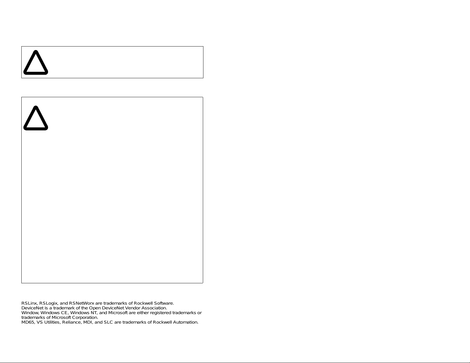
2.1 DeviceNet Module Components
➊
➋
➌
Status Indicators
MDI Connector A 20-pin, single-row shrouded male
DeviceNet Connector A 5-pin connector to w h ic h a 5- pin linear
Node Address/Rate
Switches
Mode Jumper (J2)
Figure 2.1 – Components of the DeviceNet Module
Getting Started
Three LEDs tha t in dic ate th e st atus of the
connected drive, module, and network.
Refer to chapter 9, Troubleshooting.
header. An Internal Interface cable is
connected to this connector and a
connector on the drive. See table 2.2.
plug can be connected.
Switches for setting the node address
and network data rate.
Selects Single- or Multi-Drive mode of
operation.
➎
➍
2-1
Page 16

2.2 Required Equipment
Table 2.2 lists the equipment shipped with the DeviceNet module.
When you unpa ck the module , verify th at the packa ge inc ludes all of
these items.
Table 2.2 – Equipment Shipped with the DeviceNet Module
Item Description
DeviceNet module
15.24 cm (6 in) Internal Interface cable
Five-pin linear DeviceNet plug (connected to the DeviceNet
connector on the module)
Grounding wrist strap
DeviceNet Module User Manual (D2-3520)
Table 2.3 lists user-supplied equipment also required to install and
configure the DeviceNet module.
Table 2.3 – Required User-Supplied Equipment
Item Description
A small flathead screwdriver
DeviceNet cable
• Thin cable with an outside diameter of 6.9 mm (0.27 in.) is
recommended
Configuration tool, such as :
•LCD OIM
• VS Utilities
• RSNetWorx for DeviceNet
• Serial Converter
Computer with a DeviceNet communications module installed
(such as 1784-PCD, 1784-PCID, 1784-PCIDS, or 177-KFD)
Controller configuration software (examples: RSLogix5,
RSLogix500, or RSLogix 5000)
DeviceNet Cover Kit (replaces stan dard cover supplied with
MD65 drive when the DeviceNet module is installed).
• B-Frame: Model Number 6MD-COMMCVRB
• C-Frame: Model Number 6MD-COMMCVRC
2-2
DeviceNet Communications Module
Page 17

2.3 Installation Checklist
This section is designed to help experienced users start using the
DeviceNet module. If you are unsure how to complete a step, refer
to the referenced chapter.
Step Action Refer to
1 Review the safety precautions for the
❒
❒
❒
❒
❒
❒
module.
2 Verify that the MD65 drive is properly
installed.
3 Commission the module.
Set a unique node address and the
appropriate data rate us in g th e s w itc he s o n
the module . If desired, you can disable the
switches and use parameter settings
instead.
4 Install the module.
Verify that the MD65 drive and DeviceNet
network are not powered. Then, connect
the module to the network using a
DeviceNet cable and to the drive using the
Internal Interface cable. Use the captive
screws to secure and grou nd the mo dule to
the drive.
5 Apply power to the module.
The module receives power from the drive
and network. Apply power to the network
and to the drive. The status indicators
should be green. If they flash re d, there i s a
problem. Refer to Chapter 9,
Troubleshooting.
6 Configure the module for your
application.
Set the parameters for the following
features as required by your application:
• Node address and data rate.
• I/O configuration.
• Change of State, Cyclic, or polled I/O
data exchange.
• Fault action s.
Throughout
this manual
MD65 AC
Drive User
Manual
Chapter 3,
Installing
the
DeviceNet
Module
Chapter 4,
Configuring
the
DeviceNet
Module
Getting Started
2-3
Page 18

Step Action Refer to
7 Apply power to the DeviceNet master
❒
❒
❒
and other devices on the network.
Verify that the master and network are
installed and functio ning in accor dance with
DeviceNet standa rds, and then apply power
to them.
8 Configure the scanner to communicate
with the module.
Use a network tool such as RSNetWorx for
DeviceNet to configure the scanner on the
network. Make sure to:
• Set up the scan list.
• Map the module data to the scan list.
• Save you r Devic eNet confi guratio n to th e
scanner and a file.
9 Create a ladder logic program.
Use a programming tool such as RSLogix
to create a ladder logic program that
enables you to do the following:
• Control the module and connected drive.
• Monitor or configure the drive using
Explicit Messages.
DeviceNet
Cable
System
Planning
and
Installation
Manual
Chapter 5,
Configuring
the Scanner
Chapter 6,
Using I/O
Messaging
Chapter 7,
Using
Explicit
Messaging
2-4
DeviceNet Communications Module
Page 19
CHAPTER 3
Installing the
DeviceNet Module
Chapter 3 provides instructions for installing the DeviceNet module
in an MD65 drive.
3.1 Preparing for an Installation
Before installing the DeviceNet module:
• Read the
DN-2.5, and the
Installation Manual
provide informati on on selecti ng cable s, setting up a netw ork, and
network bas ics.
• Verify that you have all required equipment. Refer to chapter 2,
Getting Started.
3.2 Commissioning the Module
DeviceNet Product Overvi ew Manual
DeviceNet Cable System Planning and
, Publication DN-6.7.2. These manuals will
, Publication
To commission the module, you must set a unique node address
and the data rate that is used by the ne twork. (Refer to the Glossary
for details about data rates and node addresses.)
Important: New settings are recognized only when power is applied
Step 1. Set the node address and data rate switches as shown in
Step 2. Set the module mode jumper for Single- or Multi-Drive
Installing the DeviceNet Module
to the module. If you change a setting, cycle power.
ATTENTION: The DeviceNet module contains
ESD- (Electrostatic Discharge) sensitive parts that
!
can be damaged if you do not follow ESD control
procedures. S t atic contro l preca utions ar e requi red
when handling the module. Failure to observe these
precautions could result in damage to equipment.
figure 3.1.
operation. See figure 3.1 and table 3.3.
3-1
Page 20
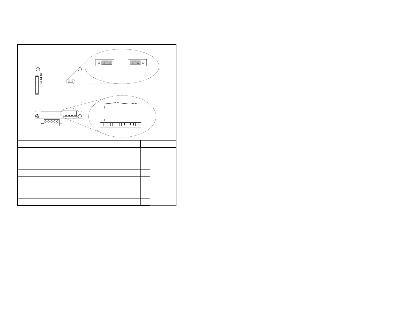
Important: If all switches are in the CLOSED position (all 0s), then
J2
J2
p
n
e
n
8
3
5
6
E
U
1
8
3
5
6
the Node Address and Data Rate are determined by
parameter settings in DN Addr Cfg (02) and DN Rate
Cfg (04).
Single Drive
eratio
O
NOD
P = OPEN =
Multi-Driv
Operatio
Switches Description Default
SW 1 Least Significant Bit (LSB) of Node Address 1
SW 2 Bit 1 of Node Address 1
SW 3 Bit 2 of Node Address 1
SW 4 Bit 3 of Node Address 1
Node 63
SW 5 Bit 4 of Node Address 1
SW 6 Most Significant Bit (MSB) of Node Address 1
SW 7 Least Significant Bit (LSB) of Data Rate 1 Autobaud
SW 8 Most Significant Bit (MSB) of Data Rate 1
Figure 3.1 – Setting the Node Address/ Data Switches and Single-/Multi-Drive
Operation Jumper
3-2
DeviceNet Communications Module
Page 21

Table 3.1 – Node Address Switch Settings (UP = OPEN = 1)
Switch Setting Node Switch Setting Node
SW 1SW 2SW 3SW 4SW 5SW 6AddressSW 1SW 2SW 3SW 4SW 5SW 6 Address
000000 0 101100 13
100000 1 011100 14
010000 2 111100 15
110000 3 000010 16
001000 4 100010 17
101000 5 010010 18
011000 6 110010 19
111000 7 001010 20
000100 8 101010 21
100100 9 011010 22
010100 10 111010 23
110100 11 000110 24
001100 12 100110 25
SW 1SW 2SW 3SW 4SW 5SW 6AddressSW 1SW 2SW 3SW 4SW 5SW 6 Address
010110 26 101101 45
110110 27 011101 46
001110 28 111101 47
101110 29 000011 48
011110 30 100011 49
111110 31 010011 50
000001 32 110011 51
100001 33 001011 52
010001 34 101011 53
110001 35 011011 54
001001 36 111011 55
101001 37 000111 56
011001 38 100111 57
111001 39 010111 58
000101 40 110111 59
100101 41 001111 60
010101 42 101111 61
110101 43 011111 62
001101 44 111111 63
Table 3.2 – Data Rate Switch Settings (UP = OPEN = 1)
Switch Setting Data
SW 7 SW 8 Rate
0 0 125 kbps
1 0 250 kbps
0 1 500 kbps
1 1 Autobaud
Installing the DeviceNet Module
3-3
Page 22
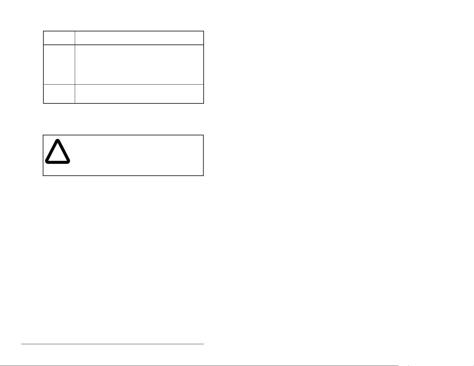
Table 3.3 – Jumper Settings for Single- or Multi-Drive Operation
Jumper
Description
Setting
Right
position or
jumper
missing
Left position Sets the module for Multi-Driv e operation mode using
Sets the module for Single-Drive mode (default
setting) using a single drive connection.
Important: In this mode, connections to multiple
drives must be removed since all powered and
connected host s will respond to a ny message s ent by
the module.
up to 5 different drives. MDI peripherals do not
operate with the module in this mode.
3.3 Connecting the Module to the
Network
ATTENTION: The drive may contain high voltages
that can cause injury or death. Remove all power
!
Step 1. Remove power from the drive.
Step 2. Use static control precautions.
Step 3. Remove the driv e cov er.
Step 4. Connect a DeviceNet cable to the network and route it
Important: Maximum cable length depends on data rate. Refer to
Step 5. Connect a 5-pin linear plug to the DeviceNet cable. Refer
from the drive, and then verify power has been
removed before inst alling or remo ving a D evic eNet
module. Failure to o bserve these pre cautions coul d
result in severe bodily injury or loss of life.
through the bottom of the MD65 drive. DeviceNet thin
cable with an outside diameter of 6.9 mm (0.27 in.) is
recommended. (See figure 3.5.)
data rate
to figure 3.2.
Note that a 10-pin linear plug is not supported. Use the
5-pin linear plug shipped with the module.
in the Glossary.
3-4
DeviceNet Communications Module
Page 23
5
4
3
2
1
Terminal Color Signal Function
5 Red V+ Power Supply
4 White CAN_H Signal High
3 Bare SHIELD Shield
2 Blue CAN_L Signal Low
1BlackV– Common
Figure 3.2 – Connecting a 5-Pin Linear Plug to the Cable
Red
White
Bare
Blue
Black
Step 6. Insert the DeviceNet cable plug into the mating module
receptacle and secure it with the two screws. (See figure
3.3, item 3.) Verify that the colors of the wires match up
with the color codes on the receptacle.
3.4 Connecting the Module to the Drive
Step 1. Remove power from the drive.
Step 2. Use static control precautions.
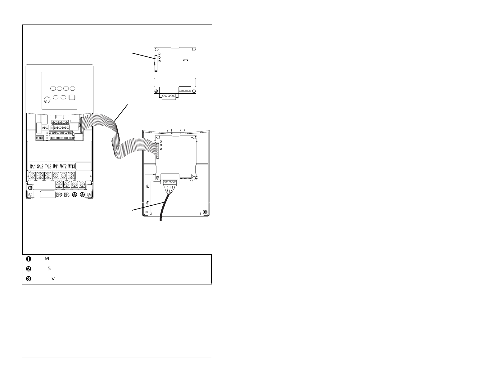
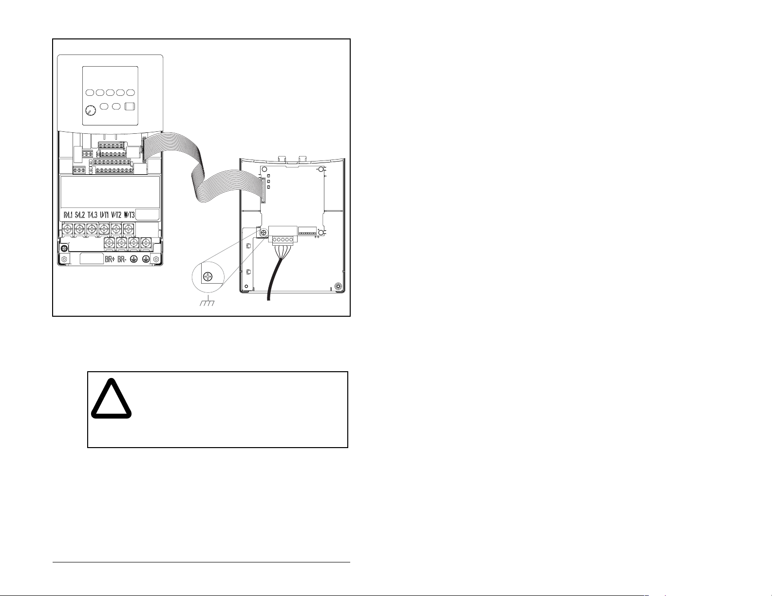
Step 3. Mount the module on the B- or C-Frame Communications
Module Cover us ing the screw on the De viceNet m odule to
secure it into place. See figure 3.3. Also, refer to the
installation manual that shipped with the Communications
Cover (D2-3523).
• B-Frame Cover: M/N 6MD-COMMCVRB
• C-Frame Cover: M/N 6MD-COMMCVRC
Important: Tighten the screw in the lower left hole to ground the
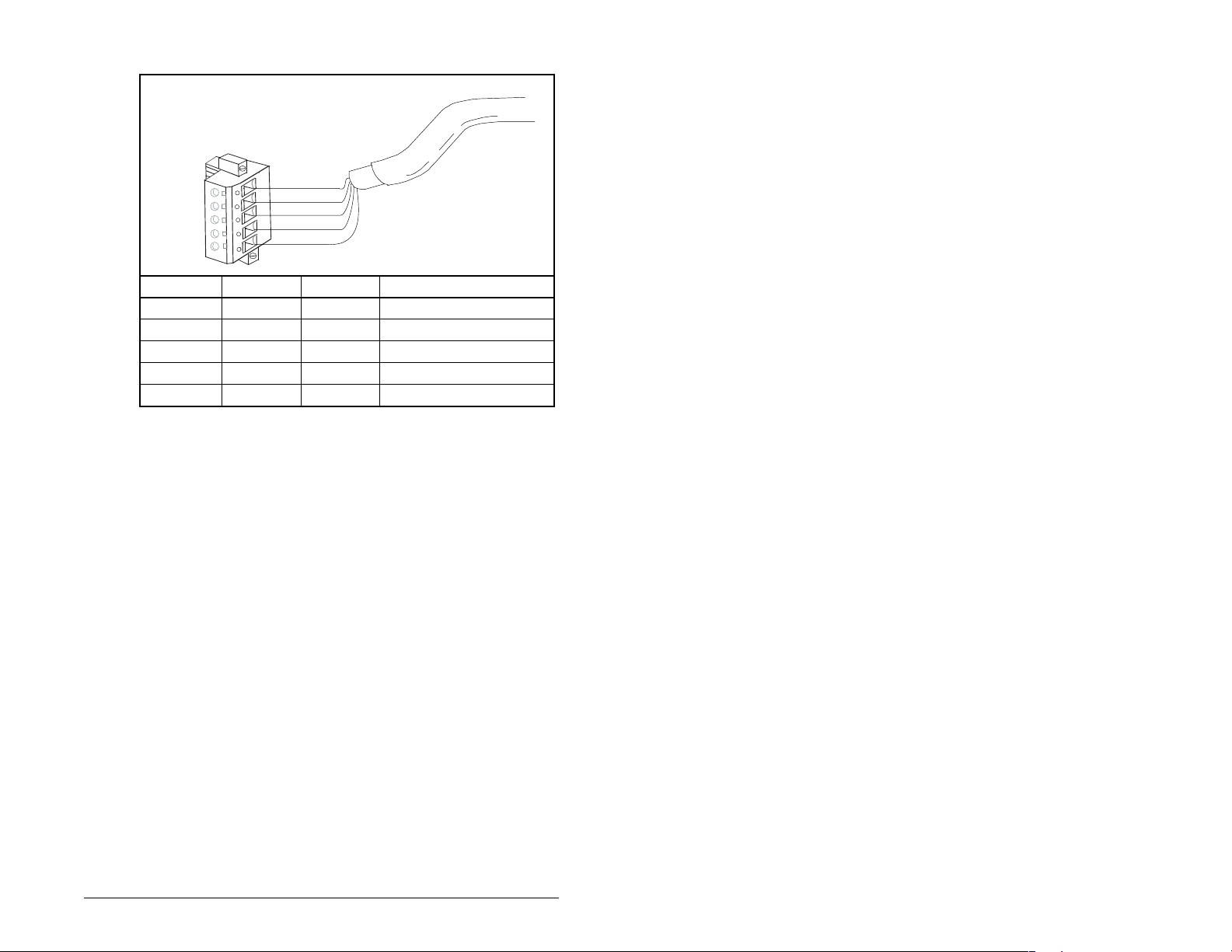
Step 4. Conne ct the Int erna l Interface cable to the MDI port on th e
module. See figure 3.4.
drive and then to the MDI connector on the module.
Installing the DeviceNet Module
3-5
Page 24
➊
➋
MDCOMM-DNET
DeviceNet Module
3-6
MD65 Drive
B and C Frames
(cover removed)
MDI connector
15.24 cm (6 in) Internal Interface cable
DeviceNet cable
Figure 3.3 – MDI Ports and Internal Interface Cables
➌
Back of Cover
6MD-COMMCVRB
6MD-COMMCVRC
DeviceNet Communications Module
Page 25
MD65 Drive
B and C Frames
(cover removed)
Figure 3.4 – Mounting the Module
3.5 Applying Power
ATTENTION: Unpredictable operation may occur if
you fail to verify that p aram eter s etting s and s witch
!
settings are compa tible with your application . Verif y
that settings are compatible with your application
before applying power to the drive. Failure to
observe these precautions could result in severe
bodily injury or loss of life.
DeviceNet Module
Mounted on Back of Cover
Step 1. Reinstall the cover on the drive. The status indicators can
be viewed on the front of the drive after power has been
applied.
Step 2. Ensure that the module will have a unique address on the
network and is set at the correct da ta rate or to autoba ud. If
a new data rate or address is needed, reset the switches
on the module (refer to section 3.2).
Installing the DeviceNet Module
3-7
Page 26

Step 3. Apply power to the drive. The module receives its power
Step 4. If the software settings for the data rate and node address
from the connected drive and network. When you apply
power to the product and network for the first time, the
status indicators should be green after an initialization. If
the status indicators are red, there is a problem. Refer to
chapter 9, Troubleshooting the DeviceNet Module and
Network.
are to be used, a configur ation tool such as VS Util ities ca n
be used to adjust th e re spe ct ive p a r am eter s in the mo dule.
3-8
DeviceNet Communications Module
Page 27

CHAPTER 4
Configuring the
DeviceNet Module
Chapter 4 provides instructions and information for setting the
parameters in the DeviceNet module.
For a list of parameters, refer to Appendix B, DeviceNet Module
Parameters. For definitions of terms in this chapter, refer to the
Glossary.
4.1 Configuration Tools
The DeviceNet module stores parameters and other information in
its own non-volatile memory. Therefore, you must access the
module to view and edi t it s p arameters. Table 4.1 lis t s the tools that
can be used to access the module parameters.
Table 4.1 – Configuration Tools
Tool Refer To:
VS Utilities Software VS Utilities online help
LCD OIM Sect ion 4.2
RSNetWorx for DeviceNet Section 4.3
RSNetWorx for DeviceNet (version 4.018) and RSLinx (version
2.40) were used for examples in this manual. Different versions of
software may differ in appearance and procedures.
Note that explicit messaging can also be used to configure a
DeviceNet module and drive. Refer to Chapter7, Using Explicit
Messaging.
Configuring the DeviceNet Module
4-1
Page 28
4.2 Using the LCD OIM to Configure the
Module
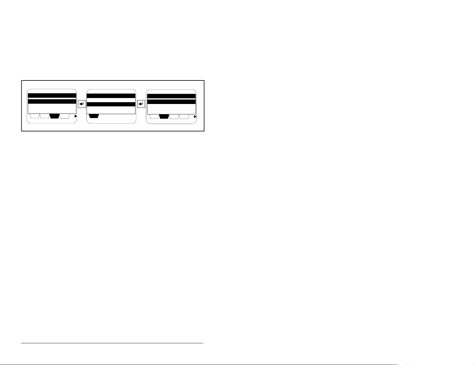
Use the procedure in figure 4.1 to access the parameters on the
DeviceNet module using the LCD OIM (M/N MD4LCD-PNL,
MD4ALCD, or MD1CC). If you are unfamiliar with the operation of
the LCD OIM, refer to the OIM Quic k Referenc e (D2-350 8) for more
information.
Device Sel e ct
MDI Devices
DIAG PARAM
DSEL
MEM
SEL
MDI Devices
MD65
MDCOMM-DNET
Parameters
Linear List
Changed Params
PARAM
DSEL
DIAG
Figure 4.1 – Accessing the DeviceNet Parameters using the LCD OIM
4.3 Using RSNetWorx for DeviceNet
RSNetWorx for DeviceNet is a Rockwell Software application that
can be used to set up Devi ceNet netwo rks and con figure conn ected
devices.
4.3.1 Setting Up RSLinx for RSNetWorx for
DeviceNet
To use RSNetWorx for DeviceNet, you must first set up a driver in
RSLinx. The driver provides a communications link between the
computer and DeviceNet network. See table 4.2 and figure 4.2 for
this procedure.
MEM
SEL
4-2
DeviceNet Communications Module
Page 29
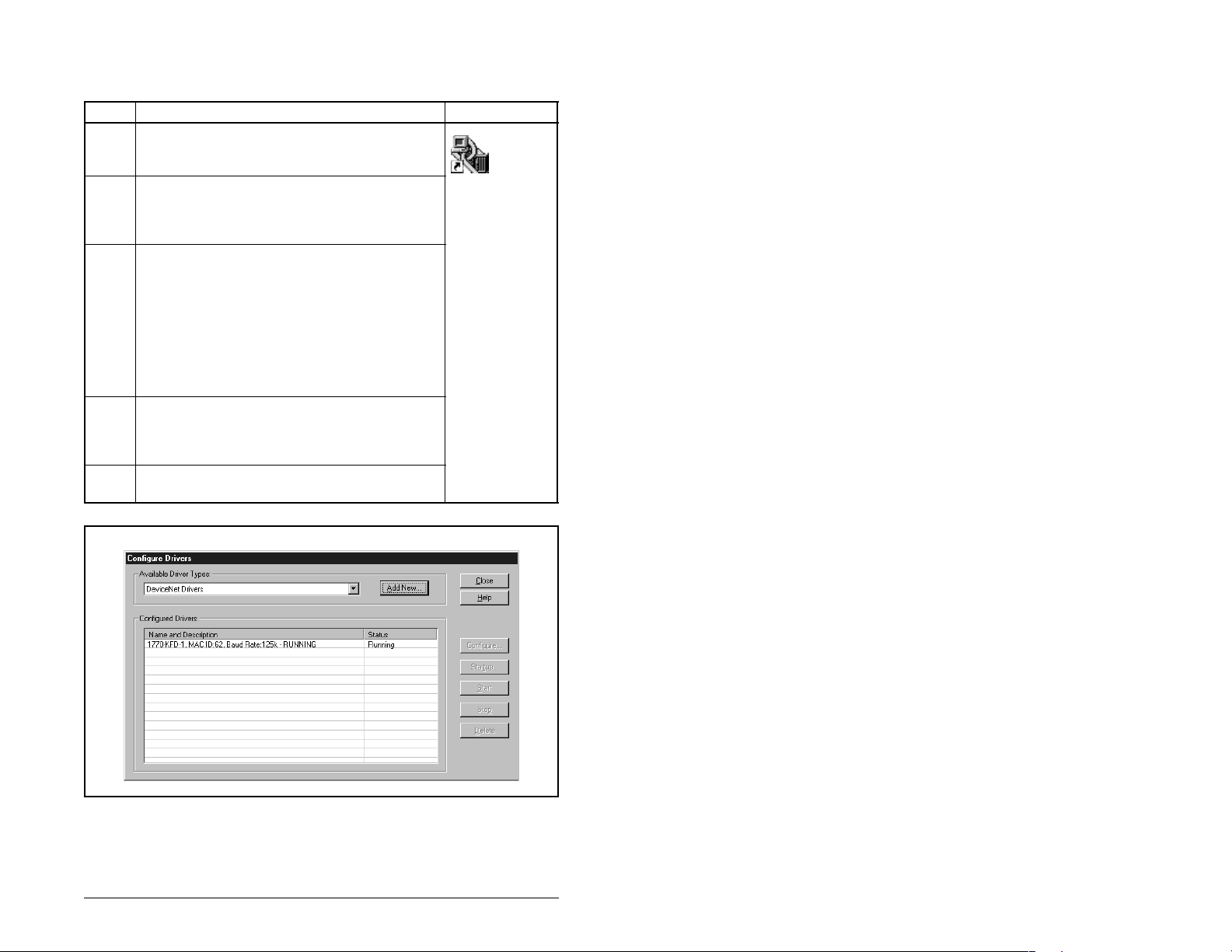
Table 4.2 – Procedure for Setting Up RSLinx for RSNetworx for DeviceNet
o
Step Action Icon
1. Start RSLinx, and select Communications >
Configure Drivers to display the Configure
Drivers dialog box. See figure 4.2.
Shortcut t
RSLinx
2. In the Available Driver Types box, select
DeviceNet Drivers, and then click Add New.
The DeviceNet Driver Selection dialog box
appears.
3. In the Available DeviceNet Drivers list, select
the module connected to your computer, and
then click Select. A Driver Configuration dia lo g
box appears.
Configure the driver for your computer and
network settings, and then click OK. The
Configure Drivers dialog box reports the
progress of the configuration. Then, the Add
New RSLinx Driver dialog box appears.
4. Type a name (if desired), and then click OK.
The Configure Drivers dialog box reappears,
and the new driver is in the Configured Drivers
List. See figure 4.2.
5. Click Close to close the dialog box. Leave
RSLinx running.
Figure 4.2 – Configure Drivers Dialog Box with a Configured Driver
Configuring the DeviceNet Module
4-3
Page 30
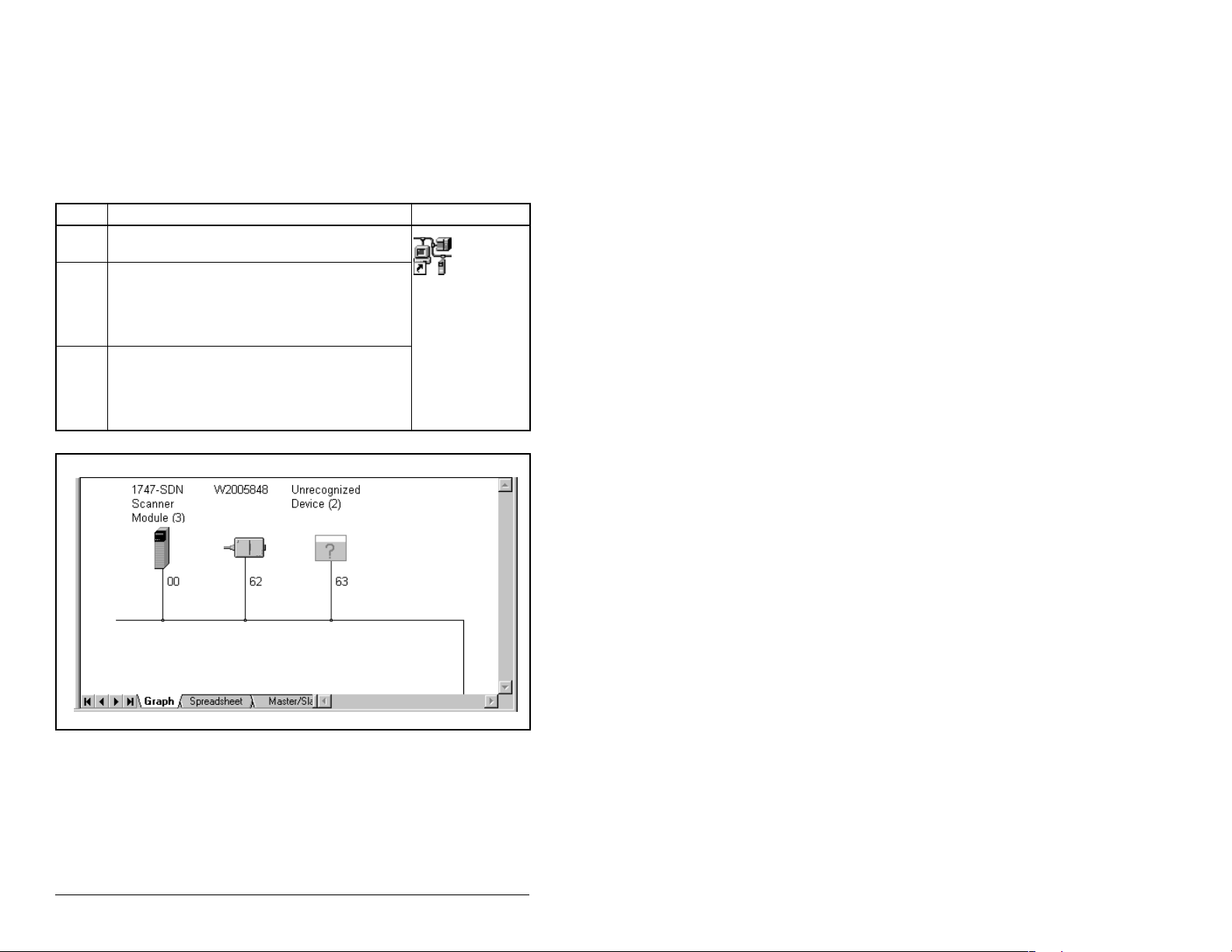
4.3.2 Going Online with RSNetWorx for DeviceNet
You can view the devices on a DeviceNet network by going online.
A device may appear as an unrecognized device (node 63 in figure
4.3) if RSNetWorx for DeviceNet does not have an Electronic Data
Sheet (EDS) file for it. See table 4.3 for the procedure to view
devices.
Table 4.3 – Viewing Devices on the DeviceNet Network using RSNetWorx
Step Action Icon
1. After setting up a driver in RSLinx, start
RSNetWorx for DeviceNet.
2. Select Network > Online. If the Browse for
Network dialog box appears, RSLinx has
multiple drivers configured. Select your
DeviceNet network, and click OK. A prompt
appears.
3. RSNetworx browses the network and any
devices on the network appear in the
Configuration View. You can select Graph,
Spreadsheet, or Master/Slave views. Figure
4.3 shows a sample network in a Graph view.
Shortcut to
RSNetWorx
4-4
Figure 4.3 – Sample DeviceNet Network (Graph View)
DeviceNet Communications Module
Page 31

4.3.3 Creating an Electronic Data Sheet (EDS) File
If the module and drive appear as an unreco gni ze d devi ce , create
an EDS file for it using the procedure in table 4.4.
Table 4.4 – Procedure for Creating an EDS File
Step Action Icon
1. Right-click the “Unrecognized Device” icon,
and select Register Device in the menu. The
EDS Wizard (figure 4.4) appears.
2. Click Next to display the next step.
3. Select Upload EDS, and then click Next.
4. Type a description (if desired), and then click
Next.
5. Under Polled, select Enabled, type 4 in the
Input Size and Output Size boxes, and then
click Next. RSNetWorx will upload the EDS file
from the drive and module.
6. Click Next to display the icon options for the
node. We recommend that you use the icon for
your product. You can change icons by clicking
Change icon.
7. Click Next to view a summary, and then click
Next again to accept it.
8. Click Finish to finish the EDS creation. A new
icon represent s the M D65 driv e and mo dule i n
the Configuration View.
MD65
AC Drive
Figure 4.4 – EDS Wizard Screen
Configuring the DeviceNet Module
4-5
Page 32

4.3.4 Accessing and Editing Parameters
Parameters in the drive and module can be edited with RSNetWorx
using the procedure in table 4.5. The module parameters are
appended to the list of drive parameters.
Table 4.5 – Procedure to Access and Edit Parameters Using RSNetWorx
Step Action Icon
1. After creating an EDS file, right-click on the
icon for the MD65 drive and module and
select Properties. The MD65 Drive dialog
box appears.
2. Click the Parameters tab (figure 4.5). If an
EDS Editor message appears, click Upload
to load the parameter values in the drive to
the computer.
Parameters are displayed in numeric al order
under Parameter. You can either scroll
through the list or select a specific group of
parameters in the Group s box. T he availab le
groups and the numbers of the module
parameters will vary based on the type of
drive that is connected to the module.
3. In the Current Value column, double-click a
value to edit it.
4. Click Apply to save changes to the device.
MD65
AC Drive
4-6
MD65 1P 110V 1.5HP
Figure 4.5 – Sample MD65 Drive Dialog Box (Drive Parameters Tab)
DeviceNet Communications Module
Page 33

4.4 Setting the Node Address
The value of DN Addr Cfg (2) determines the node address if all of
the module DIP switches are in the CLOSED position (all 0s). We
recommend that you do not use node address 63 because all new
devices use it as the default address. Address 63 is also used for
Automatic Device Recovery.
Step 1. Set the value of DN Addr Cfg (3) to a uniqu e node ad dress.
See figure 4.6.
DN Addr Cfg
Parameter: #
63
VALUE LIMITS SEL
Figure 4.6 – DeviceNet Node Address Screen on an LCD OIM
Step 2. Reset the module. Refer to section 4.9, Resetting the
Module, for this procedure.
If you are using RSNetWorx for DeviceNet, select Network >
Single Browse Path to see the new address; then delete the old
address.
4.5 Setting the Data Rate
The value of DN Rate Cfg (4) determines the Devic eNet d at a rate if
all of the module DIP switches are in the CLOSED positio n (all 0s).
The Autobaud setti ng will det ect the da ta rate used on t he netwo rk if
another device is se ttin g the da ta ra te. Your application may re quire
a different s etting.
Step 1. Set the value of DN Rate Cfg (4) to the data rate at which
your network is operating.
DN Rate Cfg
Parameter: #
Autobaud 3
VALUE LIMITS SEL
004
002
Default = 63
Value Baud Rate
0 125 kbps
1 250 kbps
2 500 kbps
3 Autobaud (Default)
Figure 4.7 – DeviceNet Data Rate Screen on an LCD OIM
Step 2. Reset the module. Refer to section 4.9 for this procedure.
Configuring the DeviceNet Module
4-7
Page 34

4.6 Setting the I/O Config uration
The I/O configuration determines the number of drives that will be
represented on the ne twork as one node by the mo dule. I f the Mode
Jumper is set to the Single-Mode position, only one drive is
represented by the module, and DSI I/O Cfg (15) has no effect. If
the Mode Jumper is set to the Multi-Drive position, up to five drives
can be represented as one node by the module.
Step 1. Set the value in DSI I/O Cfg (15).
DSI I/O Cfg
Parameter: #
Drive 0 0
VALUE LIMITS SEL
Figure 4.8 – I/O Configuration Screen on an LCD OIM
Value Description
015
0 Driv e 0 ( Def ault)
1Drives 0-1
2Drives 0-2
3Drives 0-3
4Drives 0-4
Mode Jumper Position
Single Multi-Drive
Drive 0 is the MD65 drive with the MDCOMM-DNET
module installed. Drives 1 through 4 are MD65 drives that
multi-drop to the RS485 port on Drive 0. Refer to chapter
8, Using Multi-Drive Mode for more information.
Step 2. If a drive is enabled, configure the parameters in the drive
to accept the Logic Command and Reference from the
module. For example, set Start Source (P036) and Speed
Reference (P038) in an MD65 drive to Comm Port.
Step 3. Reset the module. Refer to section 4.9 for this procedure.
4.7 Selecting COS, Cyclic, or Polled I/O
The data exchange (s ometime s called allo cation) is the method that
the module uses to exchange data on the DeviceNet network. The
module can be configured to use one of the following data
exchanges:
• COS (change of state)
• Polled and COS
•Cyclic
• Polled and cyclic
• Polled
4-8
If “polled and COS” or “polled and cyclic” is used, the module
receives the I/O from the polled messages. It transmits its Logic
Status and Feedback in COS or cyclic messages. Other data is
transmitted in polled messages.
DeviceNet Communications Module
Page 35

Cyclic and polled da ta exchanges are configured in the scanne r, so
you only need to set the I/O configuration in the module. COS data
exchange must be configured in both the module and the scanner.
You need to set the I/O configuration and COS parameters in the
module.
4.7.1 Using COS (Change of State) Data Exchange
Step 1. Set the bits in the Logic Status word that should be
checked for changes in COS Status Mask (12). The bit
definitions for the Status Mask will depend on the drive to
which you are connected. Refer to the drive
documentation.
COS Status Mask
Parameter: #
VALUE LIMITS SEL
Figure 4.9 – COS Status Mask Configuration Screen on an LCD OIM
012
0
Value Description
0 Ignore this logic bit. (Default)
1 Check this logic bit.
Step 2. Set the amount of change to the Feedback that is re quired
to trigger a Change of State message in COS Fdbk
Change (13).
COS Fdbk Change
Parameter: #
VALUE LIMITS SEL
Figure 4.10 – COS Fdbk Change Configuration Screen on an LCD OIM
.
013
0
The module is now configured for COS data exchange. You must
configure the scanner to allocate it using COS (see chapter 5,
Configuring the Scanner).
Configuring the DeviceNet Module
4-9
Page 36

4.8 Setting a Fault Action
By default, when communications are disrupted (for example, a
cable is disconnected) or the scanner is idle, the drive responds by
faulting if it is using I/O from the network.
You can configure a different response to communication
disruptions using Comm Flt Action (7) and a different response to
an idle scanner using Idle Flt Action (8).
ATTENTION: Comm Flt Action (7) and Idle Flt Action
(8) let you determine the action of the module and
!
To set the fault action:
Set the values of Comm Flt Action (7) and Idle Flt Action (8) to the
desired response s as shown in tabl e 4.6. See fig ure 4.11 for sample
LCD OIM Fault Action Screens.
connected drive if commun ications are disru pted or
the scanner is idle. By default, thes e parameters fault
the drive. You can set these para meters so th at the
drive continues to run. Precautions s hould be t aken
to ensure that the settings of these parameters do
not create a hazard of injury o r equip ment damag e.
Failure to observe thes e precauti ons cou ld result in
bodily injury or damage to, or destruction of,
equipment.
4-10
Table 4.6 – Selections for Drive Response to Communication Fault
Value Action Description
0 Fault The drive is faulted and stopped. (Default)
1 Stop The drive is stopped, but not faulted.
2 Zero Data The drive is sent 0 for output data after a
3 Hold Last The drive continues in its present state
4 Send Flt
Cfg
communications di sruption. This do es not
command a stop.
after a communications disruption.
The drive is sent the data that you set in
the fault configuration parameters Flt Cfg
Logic (10) and Flt Config Ref (11).
DeviceNet Communications Module
Page 37

Comm Flt Action
Parameter: #
007
Idle Flt Action
Parameter: #
008
Fault 0
VALUE LIMITS SEL
Figure 4.11 – Fault Action Screens on an LCD OIM
VALUE LIMITS SEL
Fault 0
Changes to these par ameters t ake ef fect immed iately. A reset is not
required.
If Multi-Drive mode is used, the same fault action is used by the
module for all of the drives it controls (Drive 0 - Drive 4).
4.8.1 Setting the Fault Configuration Parameters
If you set Comm Fl t Acti on (7 ) or I dle Flt Action (8) t o “Send Flt Cfg,”
the values in parameters shown in table 4.7 are sent to the drive
after a communications fault and/or idle fault occurs. You must set
these parameters to values required by your application.
Table 4.7 – Fault Configuration Parameters
Parameter Name Description
10 Flt Cfg Logic A 16-bit value sent to the drive for
11 Flt Cfg Ref A 16-bit value (0 – 65535) sent to
Changes to these par ameters t ake ef fect immed iately. A reset is not
required.
Logic Command.
the drive as a Reference.
Configuring the DeviceNet Module
4-11
Page 38

4.9 Resetting the Module
Changes to switch settings on some module parameters require
that you reset the module before the new settings take effect. You
can reset the module by cycling power to the drive or by using
Reset Module (6).
ATTENTION: If the module is transmitting control
I/O to the drive, the drive may faul t whe n yo u res et
!
Set Reset Module (6) to 1 = Reset Module. See figure 4.12.
the module. Determin e how your driv e w ill res pond
before resetting a connected module. Failure to
observe these precautions could result in bodily
injury or damage to equipment.
Reset Module
Parameter: #
Ready 0
VALUE LIMITS SEL
Figure 4.12 – Reset Screen on an LCD OIM
When you enter 1= Reset Module, the module will be immediately
reset. When you enter 2 = Set Defaults, the module will set all
module parameters to their factory-default settings. The value of
this parameter will be restored to 0 = Ready after the module is
reset.
006
Value Description
0 Ready (Default)
1 Reset Module
2Set Defaults
4-12
DeviceNet Communications Module
Page 39

4.10 Viewing the Module Configuration
The parameters in table 4.8 provide information about how the
module is configured. You can view these parameters at any time.
Table 4.8 – Module Configuration Parameters
Number Name Description
01 Mode The mode in which the module is set
03 DN Addr
Actual
05 DN Rate
Actual
09 DN
Active
Config
16 DSI I/O
Actual
(0 = Single drive operation, or 1 = Multi-Drive
operation).
The node address used by the module. This
will be one of the following values:
• The address set by the modul e DIP
switches 1 through 6.
• The value of DN Addr Config (2) if the
switches have been disabled.
• An old address of the switches or
parameter if they have been changed and
the module has not been reset.
The data rate used by the module. This will
be one of the following values:
• The data rate set by the module DIP
switches 7 and 8.
• The value of DN Rate Config (4) if the
switches have been disabled.
• An old data rate of the switches or
parameter if they have been changed and
the module has not been reset.
The source from which the module node
address and data rate are taken. This will be
either switches or parameters in EEPROM. It
is determined by the settings of the module
DIP switches 1 through 8.
Indicating the drives that make up the node:
Values:
0 = Drive 0
1 = Drives 0-1
2 = Drives 0-2
3 = Drives 0-3
4 = Drives 0-4
Configuring the DeviceNet Module
4-13
Page 40

4-14
DeviceNet Communications Module
Page 41

CHAPTER 5
Configuring the Scanner
A scanner is a separate module of a multi-module controller or a
built-in component of a single-module controller that provides
communication with a module connected to a network.
Chapter 5 provides instructions on how to configure a scanner to
communicate with the DeviceNet module and the connected MD65
drive.
5.1 Configuring a Simple Network:
An Example
After the module is co nfig ure d, th e c onn ec ted drive and module wil l
be a single node on the network. This chapter provides the steps
that are needed to configure a simple network like the network
shown in figure 5.1. In our example, we will configure the drive for
using Logic Command/Status and Reference Feedback over the
network.
Node 0
SLC 500 Controller with
1747-SDN Scanner
Configuring the Scanner
Node 62
Computer with 1784-PCD and
RSNetWorx for DeviceNet
DeviceNet
Node 1
MD65 Drive with
DeviceNet Module
Figure 5.1 – Sample DeviceNet Network
5-1
Page 42

5.2 Setting Up the Scan List
For the scanner to communicate with a drive, the scanner must be
configured and the drive’s node number must be added to its scan
list.
Step 1. Go online with RSNetWorx for DeviceNet. Refer to section
4.3.2. The devices on the network are displayed in the
configuration view as shown in figure 5 .2.
MD65 Drive
Figure 5.2 – Configuration View (Graph Tab)
5-2
Step 2. Right-click the DeviceNet scanner (node 00 in figure 5.2
and select Properties. The Scanner Module dialog box
appears.
Important: If your scanner is an unrecognized device, you must
create an EDS file for i t an d t hen co nfi gure it. Create an
EDS file by following the instructions in section 4.3.
Configure the scanner using the General and Module
tabs. Click Help or refer to your scanner documentation
if you need more information.
Step 3. Click the Scanlist tab. A message box prompts you to
upload.
Step 4. Click Upload. Data is uploaded fro m the scanner, and then
the Scanlist page (figure 5.3) appears.
Step 5. Select the Automap on Add box (a checkmark will
appear).
Step 6. Under Available Devi ces , s elect the drive, and then click >
(right arrow) to add it to the scanlist. See figure 5.3.
DeviceNet Communications Module
Page 43

.
01, MD65
Figure 5.3 – Scanlist Page in the Scanner Module Dialog Box
Step 7. Under Scanlist, select the drive, and then click Edit I/O
Parameters. The Edit I/O Parameters dialog box (figure
5.4) appears.
Configuring the Scanner
Figure 5.4 – Edit I/O Parameters Dialog Box
5-3
Page 44

Step 8. Select the type(s) of data exchange (Polled, Change of
State, and/or Cyclic). In our example, we selected Polled.
Step 9. Type the number of bytes that are required for your I/O in
the Input Size and Output Size boxes. The size will
depend on the I/O that you enabled in the module. This
information can be found in DSI I/O Actual (16) in the
module. Table 5.1 shows common configuration Input/
Output sizes.
In our example, we typed 4 in the Input Size and Output
Size boxes because the Mode Jumper on the module is
set to “Single” (default) and DSI I/O Active (16) is set to
“Drive 0” (only one drive being connected). Logic
Command/Referen ce us es 4 bytes and Logic St atu s/
Feedback uses 4 bytes.
Table 5.1 – Input/Output Size Configuration
Logic
Input
Output
Size
Size
44
88
12 12
16 16
20 20
Command/
Status
Reference/
Feedback
Parameter 16 -
(DSI I/O Active)
Drive 0 Single
Drives 0-1
Drives 0-2
Drives 0-3
Drives 0-4
Parameter 1 -
(Mode)
Multi-Drive
Step 10. Set the scan rate. See table 5.2.
Table 5.2 – Scan Rates
5-4
Data Exchange Rate to set
Polled Polled Rate
Change of State Heartbeat Rate
Cyclic Send Rate
Step 11. Click OK. If you changed any settings, a Scanner Applet
asks if it is OK to unmap the I/O. Click Yes to continue.
The Edit I/O Parameters dialog box closes and then the
Scanner Module dialo g box (figure 5.2 ) reappears . You will
map the I/O in the next section in this chapter.
DeviceNet Communications Module
Page 45

5.3 Mapping the Drive Data in the
Scanner
Data from I/O messages must be mapped in the scanner. This
mapping determines where a ladder logic program can find data
that is passed over the network. You must map both the Input I/O
and the Output I/O.
5.3.1 Mapping the Input I/O
Step 1. In the Scanner Module dialog box, click the Input t ab. See
figure 5.5. (If necessary, right-click the scanner in the
configuration view (figure 5.2) to display this dialog box.)
01, MD65 AC Drive
Figure 5.5 – Input Page on the Scanner Module Dialog Box
If you selected the Automap on Add box in the Scanlist page
(figure 5.3), RSNetWorx has already mapped the I/O. If it is not
mapped, click Automap to map it. If you need to change the
mapping, click Advanced and change the settings.
Step 2. In the Memory box, select a location in scanner memory
from table 5.3.
Configuring the Scanner
01, MD65 w/MDCOMM-DNET
01, MD65 w/MDCOMM-DNET
5-5
Page 46

Table 5.3 – Scanner Module Memory Locations
Scanner Memory Locations
1747-SDN Discrete or M-File
1756-DNB Assembly Data
1771-SDN Block Xfer 62 – 57
In our example, we are using a 1747-SDN and selected Discrete.
Step 3. In the Start Word box, select the word in memory at which
the data should s tar t. In our e xampl e, we selec ted 1. L ogic
Status and Speed Feedback information will be found in
I:1.1 and I:1.2, respectively.
5.3.2 Mapping the Output I/O
Step 1. In the Scanner Module dialog box, click the Output tab.
See figure 5.6. To display this dialog box, right-click the
scanner in the configuration view (figure 5.2).
01, MD65 AC Drive
5-6
01, MD65 w/MDCOMM-DNET
01, MD65 w/MDCOMM-DNET
Figure 5.6 – Output Page on the Scanner Module Dialog Box
If you selected the Automap on Add box in the Scanlist page
(figure 5.3), RSNetWorx has already mapped the I/O. If it is not
mapped, click Automap to map it. If you need to change the
mapping, click Advanced and change the settings.
DeviceNet Communications Module
Page 47

Step 2. In the Memory box, select a location in scanner memory
1747-SDN Discrete or M-File
1756-DNB Assembly Data
1771-SDN Block Xfer 62 – 57
In our example, we are using a 1747-SDN scanner and selected
Discrete.
Step 3. In the Start Word box, select the word in memory at which
from table 5.4.
Table 5.4 – Scanner Module Memory Locations
Scanner Memory Locations
the data should s tar t. In our e xampl e, we selec ted 1. L ogic
Command and S peed Refere nce dat a sh ould be w ritten to
O:1.1 and O:1.2, respectively.
5.4 Saving the Conf ig ur ation
After configuring a scanner, you must download it to the scanner.
You should also save it to a file on your computer.
Step 1. In the Scanner Module dial og box (figure 5.6), click Apply
to save the configuration to the scanner. A Scanner
Configuration Applet appears and asks if it is OK to
download the changes.
Step 2. Click Yes to download the changes. The changes are
downloaded and then the Scanner Module dialog box
reappears.
Step 3. Click OK to close the Scanner Module dialog box.
Step 4. Select File > Save. If this is the first time that you saved
the project, the Save As di alog bo x appe ars. Na vigat e to a
folder , type a file nam e, and clic k Save to save the
configuration to a file.
Configuring the Scanner
5-7
Page 48

5-8
DeviceNet Communications Module
Page 49

CHAPTER 6
Using I/O Messaging
Chapter 6 provides information and examples that explain how to
use I/O Messaging to control an MD65 drive.
ATTENTION: The examples in this publication are
intended solely for purposes of example. There are
!
6.1 About I/ O Messaging
On DeviceNet networks, I/O Messaging is used to transfer the data
that controls the MD65 drive and sets its Reference.
The DeviceNet module provides many options for configuring and
using I/O, including the following:
• The size of I/O can be configured by selecting the number of
attached dri v es (Single- or Multi-Drive mode).
• Change of state, cyclic, or polled data exchange me thods can be
used.
many variables and requirem en ts with any
application. Rockwell Automation does not assume
responsibility or liability (to include intellectual
property liability) for actual use of the examples
shown in this publication. Failure to observe this
precaution could resu lt in bodily in jury or dama ge to
equipment.
Chapter 4, Configuring the DeviceNet Module, and chapter 5,
Configuring the Scanner, discuss how to configure the DeviceNet
module and scanner on the network for these options. The Glossary
defines the dif fe rent options. This chapter discusses how to us e I/O
after you have configured the module and scanner.
Using I/O Messaging
6-1
Page 50

6.2 Understanding th e I/O Image
The DeviceNet specification requires that the terms
output
be defined from scanner’s point of view.
input
and
Output I/O is data that is o utput from the sc anner and c onsumed by
the DeviceNet module.
Input I/O is status data that is produced by the module and
consumed as input by the scanner. The I/O image table will vary
based on the configuration of the Mode Jumper (J2) on the module
and DSI I/O C onfig (15). The image table always uses consecutive
words starting at word 0.
Figure 6.1 illustrates an example of a Single-Drive I/O image (6-bit
words).
MDI
MD65 Drives
Logic Command
Reference
Logic Status
Feedback
Message
Handler
Controller
Scanner
Output
Image
(Write)
Input
Image
(Read)
Message
Handler
DeviceNet
Module
Word and I/O
0 Logic Command
1 Reference
0 Logic Status
1 Feedback
Message
Buffer
6-2
Figure 6.1 – Example of Single-Drive I/O Image
Single-Drive mode is the typic al con figuration, where one node
consists of an MD65 drive with a DeviceNet module.
For Multi-Drive m ode, where o ne n ode c an c onsist of up to 5 d rives,
refer to chapter 8, Using Multi-Drive Mode.
DeviceNet Communications Module
Page 51

6.3 Using Logic Command/Status
When enabled, the Log ic Command/Status word is always word 0 in
the I/O image. The Logic Command is a 16-bit word of control
produced by the scanner and consumed by the module. The Logic
Status is a 16-bit word of status produced by the module and
consumed by the scanner.
This manual contains the bit definitions for compatible products
available at the time of publication in Appendix D, Logic
Command/Status Words. For other products, refer to the
corresponding documentation.
6.4 Using Reference/Feedback
When enabled, Ref erence/Fee dback alw ays begin s at word 1 in t he
I/O image. The Reference (16 bits) is produced by the controller
and consumed by the module. The Feedback (16 bits) is produced
by the module and consumed by the controller.
Size Valid Values In I/O Image Example
16-bit -32768 to 32767 Word 1 Figure 6.1
6.5 Sample Ladder Logic Programs
The sample ladder logic programs work with MD65 drives.
Functions of the Sample Programs
The sample programs enable an operator to perform the following
actions:
• Obtain status information from the drive.
• Use the Logic Command to control the drive (for example, start,
stop).
• Send a Reference to the drive.
Module Settings for the Sample Programs
• Node address 1 is set using the switches.
• The module is configured for Single-Drive mode (mode jumper is
set to “Single”).
• Polled I/O was enabled during the scanner configuration.
Scanner Settings for the Example Programs
• The scanner is node 0 on the DeviceNet network.
• The scanner is in slot 1.
• The module I/O is mapped in word 0 and word 1.
• Data files, when used, are pointed out in the examples.
Using I/O Messaging
6-3
Page 52

Logic Command/St atus Words
These examples use the Logic Command word and Logic Status
word for MD65 drives. Refe r to Append ix D, Logic Co mmand/Status
Words to view these. The definition of the bits in these words may
vary if you are using a different MDI product. Refer to the
documentation for your drive.
6.5.1 Sample ControlLogix Ladder Logic Program
Table 6.1 – Tags for the Sample ControlLogix Program
Ta g Name Type Tag Name Type
Local:1:I D INT[] DriveFeedback INT
Local:1:O DINT[] DriveInputImage INT[2]
DriveCommandClearFault BOOL DriveOutputImage IN T[2]
DriveCommandJog BOOL DriveReference INT
DriveCommandStart BOOL DriveStatusFaulted BOOL
DriveCommandStop BOOL DriveStatusRunning BOOL
6-4
DeviceNet Communications Module
Page 53

Sample ControlLogix program with an MD65 drive at node address 1.
This rung enables the scanner (changes the scanner to RUN mode).
0
This section retrieves the Logic Status and Feedback data from the scanner and moves it to
specifc tags for use elsewhere in the ladder program.
1
Local:3:O.CommandRegister.Run
COP
Copy File
Source Local:3:I.Data[0]
Dest DriveInputImage[0]
Length 2
DriveInputImage[0].0
2
DriveInputImage[0].1
3
DriveInputImage[0].3
4
DriveInputImage[0].7
5
DriveInputImage[0].8
6
7 Copy File
This section takes the data from specific tags used elsewhere in the ladder program (Logic
Command bits and Reference) and writes them to the scanner for output over the network.
DriveCommandStop
8
9
10
11
DriveCommandStart
DriveCommandJog
DriveCommandClearFaults
Source DriveInputImage[1]
Dest DriveFeedback
Length 1
DriveStatusForward
DriveStatusFaulted
DriveStatusAtReference
COP
DriveOutputImage[0].0
DriveOutputImage[0].1
DriveOutputImage[0].2
DriveOutputImage[0].3
DriveStatusReady
DriveStatusActive
Figure 6.2 – Sample ControlLogix Ladder Logic Program
Using I/O Messaging
6-5
Page 54

12
DriveCommandForward
DriveOutputImage[0].4
13 /
14 Copy File
15 Copy File
DriveCommandForward
Source DriveOutputImage[0]
Dest Local:3:O.Data[0]
Length 1
DriveOutputImage[0].5
COP
Source DriveReference
Dest DriveOutputImage[1]
Length 1
COP
Figure 6.3 – Sample ControlLogix Ladder Logic Program (continued)
For the explicit mess age port ion of th is sam ple la dder pro gram, s ee
figure 7.7.
6-6
DeviceNet Communications Module
Page 55

6.5.2 Sample PLC-5 Ladder Logic Program
Table 6.2 – Control File for Block Transfers
EN ST DN ER CO EW NR TO RW RLEN DLEN FILE ELEM R G S
BT20:0000000000 62 0 9 0 0000
BT20:1000000000 62 0 10 0 0000
Sample PLC-5 program with an MD65 drive at DeviceNet node address 1.
The DeviceNet scanner gathers the drive status data via the network. The BTR in this rung
then moves the drive status data from the scanner to the N9: data file in the PLC, where:
N9:0 = Scanner Status word
N9:1 = MD65 (node 1) Logic Status
N9:2 = MD65 (node 1) Feedback
Note that the Feedback for the MD65 drive is received in Hz and not in engineering units.
For example, "300" equates to 30.0 Hz (the decimal point is always implied)
.
0000
BT20:0
EN
BTR
BTR
Block Transfer Read
Module Type 1771-SDN DeviceNet Scanner Module
Rack 000
Group 0
Module 0
Control Block BT20:0
Data File N9:0
Length 62
Continuous No
Setup Screen
EN
DN
ER
This rung enables the DeviceNet scanner.
0001
Figure 6.4 – Sample PLC-5 Ladder Logic Program
Using I/O Messaging
1771-SDN
Scanner
Enable bit
N10:0
0
6-7
Page 56

The BTR in this rung moves the drive control data to the scanner from the N10: data file in
the PLC, where:
N10:0 = Scanner Control word
N10:1 = MD65 (node 1) Logic Command
N10:2 = MD65 (node 1) Reference
Note that the Reference for the MD65 drive is set in Hz and not in engineering units.
For example, "300" equates to 30.0 Hz (the decimal point is always implied).
The scanner then sends the data to the drive over the network.
0002
BT20:1
EN
BTW
BTW
Block Transfer Write
Module Type 1771-SDN DeviceNet Scanner Module
Rack 000
Group 0
Module 0
Control Block BT20:1
Data File N10:0
Length 62
Continuous No
Setup Screen
Figure 6.5 – Sample PLC-5 Ladder Logic Program (continued)
For the explicit mess age port ion of th is sam ple la dder pro gram, s ee
figure 7.8.
EN
DN
ER
6-8
DeviceNet Communications Module
Page 57

6.5.3 Sample SLC Ladder Logic Program
SLC 5/03 example program with an MD65 at DeviceNet node address 1.
This rung enables the scanner (changes the scanner to RUN mode).
0000
This section of rungs control the Logic Command bits for the MD65 drive. The
0001
0002
0003
0004
0005
B3:0 bits would be controlled elsewhere in the user program.
Node 1
Stop
Command
B3:0
0
Node 1
Start
Command
B3:0
1
Node 1
Jog
Command
B3:0
2
Node 1
Clear Faults
Command
B3:0
3
Node 1
Forward
Command
B3:0
4
Node 1
Stop
Command
B3:0
0
Node 1
Logic Command
STOP
Node 1
Logic Command
START
Node 1
Logic Command
JOG
Node 1
Logic Command
CLEAR FAULTS
Node 1
Logic Command
FORWARD
1747-SDN
Scanner
Enable bit
O:1
1747-SDN
O:1
16
1747-SDN
O:1
17
1747-SDN
O:1
18
1747-SDN
O:1
19
1747-SDN
O:1
20
1747-SDN
0
Figure 6.6 – Sample SLC Ladder Logic Program
Using I/O Messaging
6-9
Page 58

0006
0007
0008
0009
0010
Node 1
Forward
Command
B3:0
4
This rung controls the Reference for the MD65 drive. N7:0 would be controlled
elsewhere in the user program. Note that the Reference for the MD65 drive is set
in Hz and not in engineering units. For example, "300" equates to 30.0 Hz
(the decimal point is always implied).
This section of rungs displays the Logic Status bits for the MD65 drive. The B3:1
bits would be used elsewhere in the user program.
Node 1
Logic Status
READY
I:1
16
1747-SDN
Node 1
Logic Status
ACTIVE
I:1
17
1747-SDN
Node 1
Logic Status
ROTATING
FORWARD
I:1
19
1747-SDN
Node 1
REFERENCE
(Hz)
Node 1
Logic Command
REVERSE
O:1
21
1747-SDN
MOV
MOV
Move
Source N7:0
300<
Dest O:1.2
300<
Node 1
READY
B3:1
Node 1
ACTIVE
B3:1
Node 1
ROTATING
FORWARD
B3:1
3
0
1
6-10
Figure 6.7 – Sample SLC Ladder Logic Program (continued)
DeviceNet Communications Module
Page 59

0011
0012
0013
Node 1
Logic Status
FAULTED
I:1
23
1747-SDN
Node 1
Logic Status
AT REFERENCE
I:1
This rung displays the Feedback word for the MD65 drive. N7:1 would be used
elsewhere in the user program. Note that the Feedback for the MD65 drive is set
in Hz and not in engineering units. For example, "300" equates to 30.0 Hz
(the decimal point is always implied).
24
1747-SDN
Node 1
FEEDBACK
(Hz)
MOV
MOV
Move
Source I:1.2
300<
Dest N7:1
300<
Node 1
FAULTED
B3:1
7
Node 1
AT REFERENCE
B3:1
8
Figure 6.8 – Sample SLC Ladder Logic Program (continued)
Using I/O Messaging
6-11
Page 60

6-12
DeviceNet Communications Module
Page 61

CHAPTER 7
Using Explicit
Messaging
Chapter 7 provides information and examples that explain how to
use Explicit Messaging to mon itor and configure the module and the
connected MD65 drive.
ATTENTION: The examples in this publication are
intended solely for p urposes of example. There are
!
many variables and requirem en ts with any
application. Rockwe ll Automatio n does not assume
responsibility or liability (to include intellectual
property liability) for actual use of the examples
shown in this publication. Failure to observe this
precaution could resu lt in bodily i njury or dama ge to
equipment.
ATTENTION: If Explicit Messages are programmed
to write parameter data to non-volatile storage
(NVS) frequently , the NVS will qu ickly exceed its life
cycle and cause the drive to malfunction. Do not
create a program that frequently uses Explicit
Messages to write parameter data to NVS. Failure
to observe this prec aution could result in dam age to,
or destruction of, equipment.
7.1 About Explicit Messaging
Explicit Messaging is used to transfer data that does not require
continuous updates. With Explicit Messaging, you can configure
and monitor a slave devic e’s parameters on the DeviceNet network.
Using Explicit Messaging
7-1
Page 62

7.2 Formatting Explicit Messages for a
ControlLogix Controller
ControlLogix scanners accommodate both downloading Explicit
Message Requests and uploading Explicit Message Responses.
The scanner module can accommodate one request or response
for each transaction block. Each transaction block must be
formatted as shown in figu re 7.1. Re fer to ta ble 7.1 for a de script ion
of the data that is required in each box (items 1–9).
Figure 7.1 – ControlLogix Message Format in RSLogix 5000
To display the Message Configuration dialog box in RSLogix 5000,
add a message instruction, create a tag for the message
(properties: base tag, MESSAGE data type, controller scope), and
click the blue box inside the message.
7-2
When using a 1756-DNB scanner, five Explicit Messages can be
executed at a time.
DeviceNet Communications Module
Page 63

Table 7.1 – ControlLogix Message Requests and Responses
Box Description
Message Type
The message type must be CIP Generic.
Service Type/Service Code
The service type/code is the requested DeviceNet
service. Available services depend on the class and
instance that you are using. Refer to Appendix C,
DeviceNet Objects.
Class
The object type is a DeviceNet class. Refer to
Appendix C, DeviceNet Objects, for available classes.
Instance
The object ID is an inst anc e of a Devic eNe t class. Refer
to Appendix C, DeviceNet Objects, for available
instances.
Attribute
The attribute is a class or instance attribute. Refer to
Appendix C, DeviceNet Objects, for available attributes.
Source Element
This box contains the name of the tag for any service
data to be sent from the scanner to the module and
drive. A tag must be specified even if it is not used.
Source Length
This box cont ain s the numb er of b ytes of se rvice dat a to
be sent or received in the message.
Destination
This box contains the name of the tag that will receive
service response d at a f r om the m od ule and drive. A tag
must be specified even if it is not used.
Path
The path includes the following:
• Name of the DeviceNet scanner.
• Communic ati on port on the front of the 1756-D NB
scanner. Always 2.
• Node address of the DeviceNet module. This is set
with switches or pa ramete rs in the DeviceNet modu le.
Click Browse to find the path or type in the name of a
module that you previously mapped.
Using Explicit Messaging
7-3
Page 64

7.3 Formatting Explicit Messages for a
PLC or SLC Controller
Transaction blocks in PLC and SLC scanners accommodate both
downloading Explicit Message Requests and uploading Explicit
Message Responses. The scanner module can accommodate one
request or response for each transaction block. Each transaction
block must be formatted as shown in fi gure 7.2 or figure 7.3.
Request Response
Bit 15 0 15 0
Word 0 TXID Command TXID Status
Port Size Port Size
Service Address Service Address
Class Service Response Data
Instance
Attribute
Word 6 - 31 Service Data
Word 32 TXID Command TXID Status
Port Size Port Size
Service Address Service Address
Class Service Response Data
Instance
Attribute
Word 38 - 63 Service Data
Figure 7.2 – PLC Explicit Message Format
7-4
Request Response
Bit 15 0 15 0
Word 0 TXID Command TXID Status
Port Size Port Size
Service Address Service Address
Class Service Response Data
Instance
Attribute
Word 6 - 31 Service Data
Figure 7.3 – SLC Explicit Message Format
Refer to tables 7.2 and 7.3 for a description of the data that is
required in each word.
DeviceNet Communications Module
Page 65

Table 7.2 identifies the number of transaction blocks within a
scanner that are reserved for Explicit Messaging.
Table 7.2 – Number of Transaction Blocks Reserved for Explicit Messaging
Scanner
No. of Transaction
Blocks
Words in Each
Transaction Block Refer To
1747-SDN 10 32 Figure 7.3
1771-SDN 10 32 (two blocks can
Figure 7.2
be moved at once)
Table 7.3 – PLC / SLC Explicit Message Requests
Word Description
0 Command (Least Significant Byte)
The Command is a code that instructs the scanner how to
administer the request during each download.
00 = Ignore transaction block (empty)
01 = Execute this transaction block
02 = Get status of transaction TXID
03 = Reset all client/server transactions
04 = Delete this transaction block (available only for SLC)
05 – 255 = Reserved
TXID (Most Significant Byte)
The Transaction ID is a 1-byte integer between 1 and 255. It is
assigned in the ladder logic program when the processor creates
and downloads a request to the scanner. The scanner uses it to
track the transaction to completion. It returns this value with the
response that matches the request downloaded by the processor.
1 Size (Least Significant Byte)
The size of the service data is in bytes. Service data includes the
words for the class, instance, attribute, and any data. The
maximum size is 58 bytes (29 words).
Port (Most Significant Byte)
The port that is used by the message is always zero (Channel A)
on an SLC scanner. It is zero (Channel A) or one (Channel B) for a
PLC scanner.
2 Address (Least Significant Byte)
The node address of the slave device to which the transaction is
sent. For the Explicit Message to be successful, the slave device
must be in the scanlist of the scanner, and it must be online.
Service (Most Significant Byte)
Available services depend on the class and instance that you are
using.
Refer to Appendix C, DeviceNet Objects.
3 Class
Refer to Appendix C, DeviceNet Objects, for available classes.
4 Instance
Refer to Appendix C, DeviceNet Objects, for available instances.
5 Attribute
Refer to Appendix C, DeviceNet Objects, for available attributes.
6 – 31 Request Data
This is data used for the message. For example, it may be the
value written to a parameter.
Using Explicit Messaging
7-5
Page 66

Table 7.4 – PLC / SLC Explicit Message Responses
Word Description
0 Status (Least Significant Byte)
One of the following status codes is provided during each upload:
00 = Ignore transaction block (empty)
01 = Transaction completed successfully
02 = Transaction in progress (not ready)
03 = Slave not in scan list
04 = Slave offline
05 = DeviceNet port disabled or offline
06 = Transaction TXID unknown
08 = Invalid command code
09 = Scanner out of buffers
10 = Other client/server transaction in progress
11 = Could not connect to slave device
12 = Response data too large for block
13 = Invalid port
14 = Invalid size specified
15 = Connection busy
16 – 255 = Reserved
TXID (Most Significant Byte)
The transaction ID is a 1-byte integer in word 31 with a range of 1 to
255. It is assigned in the ladder logic program when the processor
creates and downloads a request to the scanner. The scanner uses
it to track the transaction to completion. It returns this value with the
response that matches the request downloaded by the processor.
1
Size (Least Significant Byte)
The size of the service data is in bytes. The service data includes
words used for the response data. The maximum size is 58 bytes
(29 words).
Port (Most Significant Byte)
The port that is used by the message is always zero (Channel A) on
an SLC scanner. It is zero (Channel A) or one (Channel B) for a
PLC scanner.
2
Address (Least Significant Byte)
The node address of the slave device to which the transaction is
sent. For the Explicit Message to be successful, the slave device
must be in the scanlist of the scanner, and it must be online.
Service (Most Significant Byte)
If the message was successful, 0x80 is added to the service. If it is
unsuccessful, 0x94 is returned.
3 - 31
Response Data
This is data used for the message. For example, it may be the
value read from a parameter.
7-6
Refer to table 7.3 for a description of the words in a PLC/SLC
Explicit Message request.
DeviceNet Communications Module
Page 67

7.4 Running Explicit Messages
There are five basic events in the Explicit Messaging process as
shown in figure 7.4. Th e details of each step will vary depending on
the controller (ControlLogix, PLC, or SLC). Refer to the
documentation for your controller.
Important: There must be a request message and a response
message for all Explicit Messages, whether you are
reading or writing data.
Set up and send Explicit
Message Request
Complete Explicit
Message
Retrieve Explicit
Message Response
You format the required data and set up the ladder logic
program to send an Explicit Message reque st to the sc anner
module (download).
The scanner module transmits the Explicit Message
Request to the slave device over the DeviceNet network.
The slave device transmits the Explicit Message Response
back to the scanne r. The data is store d i n t he sc an ner buffer.
The controller retrieves the Explicit Mess age Response fro m
the scanner’s buffer (upload).
The Explicit Message is co mp lete. If you are using a PLC or
SLC, delete the transaction ID so that it can be reused.
2
Using Explicit Messaging
Figure 7.4 – Explicit Message Process
7-7
Page 68

7.5 ControlLogix Example
Data Format for a Read and Write Parameter
The data in this example is for an MD65 drive at node address 1.
Refer to section 7.2 for a description of the content in each box.
7-8
Configuration Value Description Refer to . . .
Service Code
Object Type
Object ID
Object Attribute
Figure 7.5 – Data Format for a Read and Write Parameter (1 of 2)
e (hex)
f (hex)
39 (dec)
1 (hex)
Get_Attribute_Single
Parameter Object
Parameter Address
Parameter Value
DeviceNet Communications Module
Page C-10
Page C-8
Page C-9
Page 69

Configuration Value Description Refer to . . .
Service Code
Object Type
Object ID
Object Attribute
Figure 7.6 – Data Format for a Read and Write Parameter (2 of 2)
Table 7.5 – Tags for the Sample Explicit Messaging Program
Tag Names
for Read Message Type
PerformParameterRead BOOL PerformParameterWrite BOOL
ParameterRDMessage MESSAGE ParameterWRMessage MESSAGE
ParameterRDValue INT ParameterWRValue INT
10 (hex)
f (hex)
39 (dec)
1 (hex)
Get_Attribute_Single
Parameter Object
Parameter Address
Parameter Value
Tag Na mes
for Write Messages Type
Page C-10
Page C-8
Page C-9
Using Explicit Messaging
7-9
Page 70

Ex plic it M essaging Ex am ple
Ex plic it M essaging Ex am ple
16
PerformParameterRead
Type - CIP Generic
Message Control ParameterRDMessage
MS G
...
EN
DN
ER
17
(End)
PerformParameterWrite
Type - CIP Generic
Message Control ParameterWRMessage
MS G
Figure 7.7 – Sample ControlLogix Ladder Logic Program
For the I/O message portion of this sample ladder program, see
figure 6.3.
...
EN
DN
ER
7-10
DeviceNet Communications Module
Page 71

7.6 PLC-5 Example
Data Format for a Read and Write Parameter
The data in this example is for an MD65 drive at node address 1.
Refer to section 7.2 for a description of the content of the data file.
Table 7.6 – Request Data for Read of Drive Parameter 39
Address Value (hex) Description Refer to ...
N11:0 0101 TXID = 01, Command = 01 (execute) Section 7.3
N11:1 0006 Port = 00, Size = 06 bytes Section 7.3
N11:2 0E01 Service = 0E (Get_Attribute_Single) Page C-10
Address = 01 (Node Address) Section 7.3
N11:3 000F Class = 0F (Parameter Object) Page C-8
N11:4 0027 Instance = Parameter 39 (27 hex)
N11:5 0001 Attribute = 01 (Parameter Value) Page C-9
Table 7.7 – Response Data for Read of Drive Parameter 39
Address Value (h ex) Description Refer to ...
N11:100 0101 TXID = 01, Status = 01 (successful) Section 7.3
N11:101 0002 Port = 00, Size = 02 bytes Section 7.3
N11:102 8E01 Service = 8E (successful),
Address = 01 (Node Address)
N11:103 0064 Response Data = 1000 100 (64 HEX) = 10.0
seconds
Section 7.3
Table 7.8 – Request Data for Write to Drive Parameter 101
Address Value (hex) Description Refer to ...
N11:0 0101 TXID = 01, Command = 01 (execute) Section 7.3
N11:1 0008 Port = 00, Size = 08 bytes Section 7.3
N11:2 1001 Service = 10 (Set_Attribute_Single) Page C-10
Address = 01 (Node Address) Section 7.3
N11:3 000F Class = 0F (Parameter Object) Page C-8
N11:4 0027 Instance = Parameter 39 (27 hex)
N11:5 0001 Attribute = 01 (Parameter Value) Page C-9
N11:6 0064 Data = 100 (64 hex) = 10.0 seconds
Table 7.9 – Response Data for Write to Drive Parameter 101
Address Value (h ex) Description Refer to ...
N11:100 0101 TXID = 01, Status = 01 (successful
transaction)
N11:101 0000 Port = 00, Size = 00 bytes Section 7.3
N11:102 9001 Service = 90 (successful)
Address = 01 (Node Address)
Using Explicit Messaging
Section 7.3
Section 7.3
7-11
Page 72

Ladder Logic Program
Explicit Messaging Example
When B3:0/0 is set to ON, a one-time BTW sends the explicit message data (starts at N11:0)
to the scanner. The MOV instruction then initializes the first word of the data file that is
used by the BTR instruction in the next rung.
Send
Explicit
Message
0003
B3:0
0
B3:0
ONS
1
BTW
BTW
Block Transfer Write
Module Type 1771-SDN DeviceNet Scanner Module
Rack 000
Group 0
Module 0
Control Block BT20:2
Data File N11:0
Length 64
Continuous No
Setup Screen
MOV
MOV
Move
Source 0
0<
Dest N11:100
257<
EN
DN
ER
0004
0005
7-12
When the BTW is complete (BT20:2.DN = ON), the CMP instruction compares the first
word of data sent from the scanner to the first word of data sent by the program to the
scanner. When the messaging function is complete, the two words will be equal. The explicit
message response data is stored starting at N11:100.
BT20:2
DN
CMP
CMP
Comparison
Expression N11:100 <> N11:0
BTR
BTR
Block Transfer Read
Module Type 1771-SDN DeviceNet Scanner Module
Rack 000
Group 0
Module 0
Control Block BT20:3
Data File N11:100
Length 64
Continuous No
Setup Screen
BT20:3
EN
EN
DN
ER
END
Figure 7.8 – Sample PLC-5 Ladder Logic Program
DeviceNet Communications Module
Page 73

7.7 SLC Example
Data Format for a Read and Write Parameter
The data in this example is for an MD65 drive at node address 1.
Refer to section 7.2 for a description of the content of the data file.
Table 7.10 – Request Data for Read of Drive Parameter 101
Address Value (hex) Description Refer to ...
N9:10 0101 TXID = 01, Command = 01 (execute) Section 7.3
N9:11 0006 Port = 00, Size = 06 bytes Section 7.3
N9:12 0E01 Service = 0E (Get_Attribute_Single) Page C-10
Address = 01 (Node Address) Section 7.3
N9:13 000F Class = 0F (Parameter Object) Page C-8
N9:14 0027 Instance = Parameter 39 (27 hex)
N9:15 0001 Attribute = 01 (Parameter Value) Page C-10
Table 7.11 – Response Data for Read of Drive Parameter 101
Address Value (hex) Description Refer to ...
N9:50 0101 TXID = 01, Status = 01 (successful) Section 7.3
N9:51 0002 Port = 00, Size = 02 bytes Section 7.3
N9:52 8E01 Service = 8E (successful)
Address = 01 (Node Address)
N9:53 0064 Response Data = 100 (64 hex) = 10.0 seconds
Table 7.12 – Request Data for Write to Drive Parameter 101
Address Value (hex) Description Refer to ...
N9:10 0101 TXID = 01, Command = 01 (execute) Section 7.3
N9:11 0008 Port = 00, Size = 08 bytes Section 7.3
N9:12 1001 Service = 10 (Set_Attrib ute_Single) Page C-10
Address = 01 (Node Address) Section 7.3
N9:13 000F Class = 0F (Parameter Object) Page C-8
N9:14 0027 Instance = Parameter 39 (27 hex)
N9:15 0001 Attribute = 01 (Parameter Value) Page C-9
N9:16 0064 Data = 100 (64 hex) = 10.0 seconds
Section 7.3
Table 7.13 – Response Data for Write to Drive Parameter 101
Address Value (hex) Description Refer to ...
N9:50 0101 TXID = 01, Status = 01 (successful transaction) Section 7.3
N9:51 0000 Port = 00, Size = 00 bytes Section 7.3
N9:52 9001 Se rvice = 90 (success ful)
Address = 01 (Node Address)
Using Explicit Messaging
Section 7.3
7-13
Page 74

Ladder Logic Program
Important: T o origina te a scanner tran saction, us e a copy operation
to M0:[slot number]:224. Then, use a copy operation to
read M1:1.224 for the result. If more th an on e message
is enabled, use the TXID to determine which message
you are reading.
Explicit Messaging Example
When B3:2/0 is set ON, this rung will copy the 32 words of Explicit Message from
the buffer at N9:10 to the M0 File Explicit Message buffer. The scanner will send
the message out over DeviceNet.
0014
0015
B3:2
0
When I:1.0/15 is ON (response to the explicit message is available), the response
message is copied into N9:50. A "4" command is copied into the M0 file, which
commands the 1747-SDN to discard the response data so that the buffer can be used
for the next message.
I:1
15
1747-SDN
COP
COP
Copy File
Source #N9:10
Dest #M0:1.224
Length 32
COP
COP
Copy File
Source #M1:1.224
Dest #N9:50
Length 32
B3:2
U
0
0016
7-14
EQU
EQU
Equal
Source A N9:10
257<
Source B N9:50
257<
MVM
MVM
Masked Move
Source N9:0
4<
Mask 00FFh
255<
Dest M0:1.224
?<
END
Figure 7.9 – Sample SLC Ladder Logic Program
For the I/O message portion of this sample ladder program, see
figure 6.6.
DeviceNet Communications Module
Page 75

CHAPTER 8
Using Multi-Drive Mode
Chapter 8 provides information and a ControlLogix ladder example
to explain how to use Multi-Drive mode.
ATTENTION: Hazard of injury or equipment
damage exists. The examples in this publication are
!
8.1 Single-Drive Mode vs. Multi-Drive
Mode
Single-Drive mode is a typical network installation, where a single
DeviceNet node consists of a single drive with an MDCOMM-DNET
module (figure 8.1).
intended solely for purp oses of ex ample. There are
many variables and requirem en ts with any
application. Rockwel l Automation d oes not assum e
responsibility or liability (to include intellectual
property liability) for actual use of the examples
shown in this publication.
MD65 Drive
with MDCOMM-DNET
Figure 8.1 – Example of a Single-Drive Mode Network
Multi-Drive mode is an altern ative to the typic al network inst allati on,
where a single DeviceNet node can consist of one to five drives
(figure 8.2). The first drive must be an MD65 drive with an
MDCOMM-DNET module. The remaining drives can be MD65 or
MD60 drives, and they are da is y-c ha ine d ov er R S-48 5 w ith the fi rst
drive.
Using Multi-Drive Mode
1 drive per node
MD65 Drive
with MDCOMM-DNET
DeviceNet
MD65 Drive
with MDCOMM-DNET
8-1
Page 76

MD65 Drive
up to 5 drives per node
DeviceNet
Up to 4 MD65 or MD60 Drives
AK-U0-RJ45-TB2P
Connector w/3rd Party
Terminating Resistor
MDCOMM-DNET
AK-U0-RJ45-TB2PRS-485
Figure 8.2 – Example of a Multi-Drive Mode Network
AK-U0-RJ45-TB2P
Connector w/3rd Party
Terminating Resistor
Benefits of Multi-Drive mode include:
• Lower hardware costs. Only one MDCOMM-DNET module is
needed for up to five d rives. M D60 drive s can a lso be us ed for the
daisy-chained drives instead of MD65 drives.
• Reduces the network node count (DeviceNet is 63 nodes
maximum). For example, in Single-Drive mode 30 drives would
consume 30 nodes. In Multi-Drive mode, 30 drives can be
connected in 6 nodes.
• Provides a means to put MD60 drives on DeviceNet (MD60
drives do not have an internal communications module slot).
• Controller can control, monitor, and read/write parameters for all
five drives.
The trade-offs of Multi-Drive mode include:
• If the MD65 drive with the MDCOMM-DNET module is powered
down, then communications with the daisy-chained drives are
disrupted, and the drives will take the appropriate
communications loss action set in each drive.
• Communications throughput to the daisy-chained drives will be
slower than if each drive was a separate node on DeviceNet
(Single-Drive mode). This is becau se the MD C OMM -D NE T
module must take the DeviceNet data for the other drives and
sequentially send the respective data to each drive over RS-485.
The approximate additional throughput time for Logic
Command/Reference to be transmitted and receiv ed by each
drive is shown in table 8.1.
8-2
DeviceNet Communications Module
Page 77

:
Table 8.1 – Additional Throughput Time for Logic Command/Reference
Drive
MD65 w/MDCOMM-DNET 0 ms
MD65 w/MDCOMM-DNET plus 1 drive +24 ms
MD65 w/MDCOMM-DNET plus 2 drives +48 ms
MD65 w/MDCOMM-DNET plus 3 drives +72 ms
MD65 w/MDCOMM-DNET plus 4 drives +96 ms
• Automatic Device Replacement (ADR) cannot be used with any
of the drives.
• The RSNetWorx Par ameter editor cannot be us ed.
• Since the RS-485 ports are used for daisy-chaining the drives,
there is no connection for a peripheral device such as an OIM.
• The AK-U0-RJ45-SC1 Splitter Cable cannot be used to add a
second connection for a peripheral device.
8.2 System Wiring
To daisy-chain t he drives off the MD65 drive w ith the
MDCOMM-DNET module (Drive 0), use the AK-U0-RJ45-TB2P
terminal block connector (figure 8.3).
Additional Throughput Time
versus Single-Drive Mode
Figure 8.3 – AK-U0-RJ45-TB2P Terminal Block Connector
The wiring diagram for using AK-U0-RJ45-TB2P terminal block
connectors is shown in figure 8.4.
Using Multi-Drive Mode
8-3
Page 78

MD65 Drive
r
with MDCOMM-DNET
Drive
#2
120 Ω
¼ Watt
Resistor
Figure 8.4 – AK-U0-RJ45-TB2P Connector Wiring Diagram
Drive
#3
Drive
#4
8.3 Understanding th e I/O Image
The DeviceNet specification requires that the terms
output
be defined from the scanner’s point of view. Therefore,
Output I/O is dat a tha t i s o utp ut from the scanner and consumed by
the DeviceNet module. Input I/O is status data that is produced by
the module and consumed as input by the scanner. The I/O image
table will vary based on the:
• Configuration of the Mode Jumper (J2) on the module and
parameter 15 (DSI I/O Cfg). The image table always uses
consecutive words starting at word 0.
Figure 8.5 illustrates the Multi-Drive I/O image with 16-bit words.
Drive
#5
input
120 Ω
¼ Watt
Resisto
and
8-4
DeviceNet Communications Module
Page 79

Controller
Scanner
Output
Image
(Write)
DeviceNet
Module
Word and I/O
0 Logic Command
1 Reference
2 Logic Command
3 Reference
4 Logic Command
5 Reference
6 Logic Command
7 Reference
8 Logic Command
9 Reference
MDI
MD65 Drive 0
MD65 Drive 1
MD65 Drive 2
MD65 Drive 3
MD65 Drive 4
0 Logic Status
1 Feedback
2 Logic Status
Input
Image
(Read)
Message
Handler
Figure 8.5 – Example of Multi-Drive I/O Image
3 Feedback
4 Logic Status
5 Feedback
6 Logic Status
7 Feedback
8 Logic Status
9 Feedback
Message
Buffer
MD65 Drive 0
MD65 Drive 1
MD65 Drive 2
MD65 Drive 3
MD65 Drive 4
8.4 Configuring the RS-485 Network
The following paramete rs must be set in the daisy-chained drives:
Parameter Value
P36 - (Start Source) 5 (“RS485 [MDI] Port”)
P38 - (Speed Reference) 5 (“RS485 [MDI] Port”)
A103 - (Comm Data Rate) 4 (“19.2K”)
A104 - (Comm Node Addr) 1-247 (must be unique)
A107 - (Comm Format) 0 (“RTU 8-N-1”)
Note that the RS-485 network is fixe d at 19.2K ba ud, 8 dat a bits , no
parity, and 1 stop bit.
Using Multi-Drive Mode
8-5
Page 80

Important: Comm Loss Action (A105) and Comm Loss Time
The following Multi-Drive parameters must be set in the
MDCOMM-DNET module:
15 - (DSI I/O Cfg) 0 = Drive 0 connected
17 - (Drv 0 Addr) = Parameter A104 - (Comm Node Address) in Drive 0
18 - (Drv 1 Addr) = Parameter A104 - (Comm Node Address) in Drive 1
19 - (Drv 2 Addr) = Parameter A104 - (Comm Node Address) in Drive 2
20 - (Drv 3 Addr) = Parameter A104 - (Comm Node Address) in Drive 3
21 - (Drv 4 Addr) = Parameter A104 - (Comm Node Address) in Drive 4
After setting the MDCOMM-DNET parameters, set the module
Mode Jumper from Single-Drive operation to Multi-Drive operation,
and reset the module or cycle power. Refer to section 3.2,
Commissioning the Mo dul e.
(A106) in the daisy-chained drives are not used in
Multi-Driv e mode. If the RS-485 cable is disconnected
or broken, the disconnected drive(s) will fault. On the
DeviceNet side, Comm Flt Action (7) and Idl e Flt Act ion
(8) in the MDCOMM-DNET module determine the
action taken for ALL of the drives on the Multi-Drive
node.
Parameter Value
1 = Drives 0-1 connected
2 = Drives 0-2 connected
3 = Drives 0-3 connected
4 = Drives 0-4 connected
8.5 Multi-Drive Ladder Logic Program
Example
The example ladder logic program demonstrates using Multi-Drive
mode with five drives. See figure 8.2 for a system layout diagram.
Function of the Program Example
The program example provided is for the ControlLogix, but other
controllers can also be used. The following actions can be
performed:
• View status information from the drives such as Ready, Fault, At
Speed, and Feedback.
• Control th e driv es u sing va riou s Log ic Com mand bit s (Stop, Start,
etc.) and Reference.
• Perform a single parameter read and write for each drive. The
example uses drive parameter 39 (Accel Time) for both so you
can see (read) the change after a write is performed.
8-6
DeviceNet Communications Module
Page 81

Module Settings for the Example Program
• The Mode Jumper on the module is set to the Multi-Drive
operation position. See section 3.2, Commissioning the Module.
• All DIP switches on the module are set to CLOSED (all 0s). See
section 3.2, Commis sioning the M odule. The actua l node address
will be set via a software parameter.
• The following module parameters are set:
Parameter Value Description
02 - (DN Addr Cfg) 1 DeviceNet node address
15 - (DSI I/O Cfg) 4 “Drives 0-4” — 5 drives on 1 node
17 - (Drv 0 Addr)
1
1 Modbus address of Drive 0
18 - (Drv 1 Addr) 2 Modbus address of Drive 1
19 - Drv 2 Addr) 3 Modbus address of Drive 2
20 - (Drv 3 Addr) 4 Modbus address of Drive 3
21 - (Drv 4 Addr) 5 Modbus address of Drive 4
1
The settings for these parameters must match the parameter A104 (Comm
Node Addr) settings in the respective drives.
Important: Drive node addresses change only after a power cycle.
Drive Settings for the Program Example
Parameter
P36 - (Start Source) 5 5 5 5 5
P38 - (Speed Reference) 5 5 5 5 5
A103 - (Comm Data Rate) 4 4 4 4 4
A104 - (Comm Node Addr)
A105 - (Comm Loss Action) 0 0 0 0 0
A106 - (Comm Loss Time) 5 5 5 5 5
A107 - (Comm Format) 0 0 0 0 0
1
The settings for these parameters must match the respective parameter
settings in the module (parameter 17 (Drive 0 Address) through parameter
21 (Drive 4 Address)).
Using Multi-Drive Mode
Value
Drive 0 Drive 1 Drive 2 Drive 3 Drive 4
1
12345
8-7
Page 82

8.6 ControlLogix Example
The following common Tags are used:
Tag Name Type Description
Local : 3 : I AB: 1756_D...
Local : 3 : 5 AB: 1756_D...
Drive Input Image INT [10] Input Image Table
Drive Output Image INT [10] Output Image Table
The following Tags are used for Drive 0:
Tag Name Type Description
Drive 0 Command Stop BOOL Logic Command bit 0 (STOP)
Drive 0 Command Start BOOL Logic Command bit 1 (START)
Drive 0 Command Jog BOOL Logic Command bit 2 (JOG)
Drive 0 Command Clear Faults BOOL Logic Command bit 3 (CLEAR
Drive 0 Command Forward BOOL Logic Command bit 4
Drive 0 Reference INT Speed Reference
Drive 0 Status Ready BOOL Logic Status bit 0 (READY)
Drive 0 Status Active BOOL Logic Status bit 1 (ACTIVE)
Drive 0 Status Forward BOOL Logic Status bit 3 (FORWARD)
Drive 0 Status Faulted BOOL Logic Status bit 7 (FAULT)
Drive 0 Status At Reference BOOL Logic Status bit 8 (AT SPEED)
Drive 0 Feedback INT Speed Feedback
Perform Parameter Read 0 BOOL Initiates the parameter read
Parameter RD Value 0 INT Read value of the parameter
Parameter RD Message 0 MESSAGE Get_Attribute_Single (Read)
Perform Parameter Write 0 BOOL Initiates the parameter value
Parameter WR Value 0 INT Write value to the parameter
Parameter WR Message 0 MESSAGE Set_Attribute_Single (Write)
1756-DNB I/OLocal : 3 : O AB: 1756_D...
FAULTS)
(FORWARD)
8-8
The same type of Tags are also used for Drive 1 through Drive 4.
Main Routine
The Main Routine tells the 1756-DNB scanner to run, reads the
network Input Image from the scanner, calls the various drive
control subroutines, and writes the network Output Image to the
scanner. See figure 8.6.
DeviceNet Communications Module
Page 83

ControlLogix MultiDrive example program with an MD65 drive at node address 1.
Four MD65/MD60 drives are daisy-chained to the main MD65 drive via their RJ45
ports (RS-485). In this mode, up to FIVE MD65/MD60 drives can exist on ONE
DeviceNet node.
This rung enables the scanner (changes the scanner to RUN mode).
0
This section retrieves the Logic Status and Feedback data for all five drives from
the scanner, and moves it to specific INT tags for use elsewhere in the ladder
program. The input image is as follows:
Drive Input Image (0) and Drive Input Image (1) = Drive 0 Logic Status and Feedback
Drive Input Image (2) and Drive Input Image (3) = Drive 1 Logic Status and Feedback
Drive Input Image (4) and Drive Input Image (5) = Drive 2 Logic Status and Feedback
Drive Input Image (6) and Drive Input Image (7) = Drive 3 Logic Status and Feedback
Drive Input Image (8) and Drive Input Image (9) = Drive 4 Logic Status and Feedback
1
Local:3:O.CommandRegister.Run
COP
Copy File
Source Local:3:I.Data[0]
Dest DriveInputImage[0]
Length 10
Drive 0 controls subroutine.
2
Drive 1 controls subroutine.
3 Jump To Subroutine
Drive 2 controls subroutine.
4
Drive 3 controls subroutine.
5
Drive 4 controls subroutine.
6 Jump To Subroutine
JSR
Jump To Subroutine
Routine Name Drive0
JSR
Routine Name Drive1
JSR
Jump To Subroutine
Routine Name Drive2
JSR
Jump To Subroutine
Routine Name Drive3
JSR
Routine Name Drive4
Figure 8.6 – Main Routine
Using Multi-Drive Mode
8-9
Page 84

This section writes the output image to the scanner. The output image is as follows:
Drive Output Image (0) and Drive Output Image (1) = Drive 0 Logic Command and Reference
Drive Output Image (2) and Drive Output Image (3) = Drive 1 Logic Command and Reference
Drive Output Image (4) and Drive Output Image (5) = Drive 2 Logic Command and Reference
Drive Output Image (6) and Drive Output Image (7) = Drive 3 Logic Command and Reference
Drive Output Image (8) and Drive Output Image (9) = Drive 4 Logic Command and Reference
(Note the length of the COP instruction is "5" because the Destination address is a DINT)
7
(End)
Copy File
Source DriveOutputImage[0]
Dest Local:3:O.Data[0]
Length 5
COP
Figure 8.7 – Main Routine (Continued)
Drive 0 - Drive 4 Control Routines
The Drive Co ntrol routines provide status information (Logic Status
and Feedback), control (Logic Command and Reference), and
parameter read/write for each of the respective drives. See figure
8.8 for Drive 0, figure 8.10 for Drive 1, figu re 8.1 2 for D riv e 2, fi gure
8.14 for Drive 3, and figure 8.16 for Drive 4.
8-10
DeviceNet Communications Module
Page 85

Drive 0 Control Subroutine
This section takes the data from the input area and moves it to specific tags
(Logic Status bits and Feedback) for use elsewhere in the ladder program.
DriveInputImage[0].0
0
Drive0StatusReady
DriveInputImage[0].1
1
2
3
4
5 Copy File
This section takes the data from specific tags (Logic Command bits and
Reference) and moves them to the output image area for transmission to the
scanner.
6
7
8
9
10
DriveInputImage[0].3
DriveInputImage[0].7
DriveInputImage[0].8
Drive0CommandStop
Drive0CommandStart
Drive0CommandJog
Drive0CommandClearFaults
Drive0CommandForward
Source DriveInputImage[1]
Dest Drive0Feedback
Length 1
Drive0StatusActive
Drive0StatusForward
Drive0StatusFaulted
Drive0StatusAtReference
COP
DriveOutputImage[0].0
DriveOutputImage[0].1
DriveOutputImage[0].2
DriveOutputImage[0].3
DriveOutputImage[0].4
Drive0CommandForward
11 /
12 Copy File
Using Multi-Drive Mode
DriveOutputImage[0].5
COP
Source Drive0Reference
Dest DriveOutputImage[1]
Length 1
Figure 8.8 – Drive 0 Control Routine
8-11
Page 86

Explicit Messaging Example
Drive 0 parameters are accessed by adding 17408 decimal (4400 hex) to the
desired parameter number. For example, to access Parameter 39 an Instance of
17447 (17408 + 39) is used.
PerformParameterRead0
13
Type - CIP Generic
Message Control ParameterRDMessage0
MS G
...
EN
DN
ER
PerformParameterWrite0
14
15 Return
(End)
Type - CIP Generic
Message Control ParameterWRMessage0
MS G
Figure 8.9 – Drive 0 Control Routine (Continued)
RET
...
EN
DN
ER
8-12
DeviceNet Communications Module
Page 87

Drive 1 Control Subroutine
This section takes the data from the input image area and moves it to specific
tags (Logic Status bits and Feedback) for use elsewhere in the ladder program.
DriveInputImage[2].0
0
Drive1StatusReady
DriveInputImage[2].1
1
2
3
4
5 Copy File
This section takes the data from specific tags (Logic Command bits and
Reference) and moves them to the output image area for transmission to
the scanner.
6
7
8
9
10
DriveInputImage[2].3
DriveInputImage[2].7
DriveInputImage[2].8
Drive1CommandStop
Drive1CommandStart
Drive1CommandJog
Drive1CommandClearFaults
Drive1CommandForward
Source DriveInputImage[3]
Dest Drive1Feedback
Length 1
Drive1StatusActive
Drive1StatusForward
Drive1StatusFaulted
Drive1StatusAtReference
COP
DriveOutputImage[2].0
DriveOutputImage[2].1
DriveOutputImage[2].2
DriveOutputImage[2].3
DriveOutputImage[2].4
Drive1CommandForward
11 /
12 Copy File
Using Multi-Drive Mode
DriveOutputImage[2].5
COP
Source Drive1Reference
Dest DriveOutputImage[3]
Length 1
Figure 8.10 – Drive 1 Control Routine
8-13
Page 88

Explicit Messaging Example
Drive 1 parameters are accessed by adding 18432 decimal (4800 hex) to the
desired parameter number. For example, to access Parameter 39 an Instance of
18471 (18432 + 39) is used.
PerformParameterRead1
13
Type - CIP Generic
Message Control ParameterRDMessage1
MS G
...
EN
DN
ER
PerformParameterWrite1
14
15 Return
(End)
Type - CIP Generic
Message Control ParameterWRMessage1
MS G
Figure 8.11 – Drive 1 Control Routine (Continued)
RET
...
EN
DN
ER
8-14
DeviceNet Communications Module
Page 89

Drive 2 Control Subroutine
This section takes the data from the input image area and moves it to specific
tags (Logic Status bits and Feedback) for use elsewhere in the ladder program.
DriveInputImage[4].0
0
DriveInputImage[4].1
1
2
3
4
5 Copy File
This section takes the data from specific tags (Logic Command bits and
Reference) and moves them to the output image area for transmission to the
scanner.
6
7
8
DriveInputImage[4].3
DriveInputImage[4].7
DriveInputImage[4].8
Drive2CommandStop
Drive2CommandStart
Drive2CommandJog
Source DriveInputImage[5]
Dest Drive2Feedback
Length 1
Drive2StatusReady
Drive2StatusActive
Drive2StatusForward
Drive2StatusFaulted
Drive2StatusAtReference
COP
DriveOutputImage[4].0
DriveOutputImage[4].1
DriveOutputImage[4].2
Drive2CommandClearFaults
9
Drive2CommandForward
10
Drive2CommandForward
11 /
12 Copy File
Using Multi-Drive Mode
DriveOutputImage[4].3
DriveOutputImage[4].4
DriveOutputImage[4].5
COP
Source Drive2Reference
Dest DriveOutputImage[5]
Length 1
Figure 8.12 – Drive 2 Control Routine
8-15
Page 90

Explicit Messaging Example
Drive 2 parameters are accessed by adding 19456 decimal (4C00 hex) to the
desired parameter number. For example, to access parameter 39 an Instance of
19495 (19456 + 39) is used.
PerformParameterRead2
13
Type - CIP Generic
Message Control ParameterRDMessage2
MS G
...
DN
ER
EN
PerformParameterWrite2
14
15 Return
(End)
Type - CIP Generic
Message Control ParameterWRMessage2
MS G
Figure 8.13 – Drive 2 Control Routine (Continued)
RET
...
EN
DN
ER
8-16
DeviceNet Communications Module
Page 91

Drive 3 Control Subroutine
This section takes the data from the input image area and moves it to specific
tags (Logic Status bits and Feedback) for use elsewhere in the ladder program.
DriveInputImage[6].0
0
DriveInputImage[6].1
1
2
3
4
5 Copy File
This section takes the data from specific tags (Logic Command bits and
Reference) and moves them to the output image area for transmission to the
scanner.
6
7
8
DriveInputImage[6].3
DriveInputImage[6].7
DriveInputImage[6].8
Drive3CommandStop
Drive3CommandStart
Drive3CommandJog
Source DriveInputImage[7]
Dest Drive3Feedback
Length 1
Drive3StatusReady
Drive3StatusActive
Drive3StatusForward
Drive3StatusFaulted
Drive3StatusAtReference
COP
DriveOutputImage[6].0
DriveOutputImage[6].1
DriveOutputImage[6].2
Drive3CommandClearFaults
9
Drive3CommandForward
10
Drive3CommandForward
11 /
12 Copy File
Using Multi-Drive Mode
DriveOutputImage[6].3
DriveOutputImage[6].4
DriveOutputImage[6].5
COP
Source Drive3Reference
Dest DriveOutputImage[7]
Length 1
Figure 8.14 – Drive 3 Control Routine
8-17
Page 92

Explicit Messaging Example
Drive 3 parameters are accessed by adding 20480 decimal (5000 hex) to the
desired parameter number. For example, to access parameter 39 an Instance of
20519 (20480 + 39) is used.
PerformParameterRead3
13
Type - CIP Generic
Message Control ParameterRDMessage3
MS G
...
DN
EN
ER
PerformParameterWrite3
14
15 Return
(End)
Type - CIP Generic
Message Control ParameterWRMessage3
MS G
Figure 8.15 – Drive 3 Control Routine (Continued)
RET
...
DN
EN
ER
8-18
DeviceNet Communications Module
Page 93

Drive 4 Control Subroutine
This section takes the data from the input image area and moves it to specific
tags (Logic Status bits and Feedback) for use elsewhere in the ladder program.
DriveInputImage[8].0
0
Drive4StatusReady
DriveInputImage[8].1
1
2
3
4
5 Copy File
This section takes the data from the specific tags (Logic Command bits and
Reference) and moves them to the output image area for transmission to the
scanner.
6
7
8
9
10
DriveInputImage[8].3
DriveInputImage[8].7
DriveInputImage[8].8
Drive4CommandStop
Drive4CommandStart
Drive4CommandJog
Drive4CommandClearFaults
Drive4CommandForward
Source DriveInputImage[9]
Dest Drive4Feedback
Length 1
Drive4StatusActive
Drive4StatusForward
Drive4StatusFaulted
Drive4StatusAtReference
COP
DriveOutputImage[8].0
DriveOutputImage[8].1
DriveOutputImage[8].2
DriveOutputImage[8].3
DriveOutputImage[8].4
Drive4CommandForward
11 /
12 Copy File
Using Multi-Drive Mode
DriveOutputImage[8].5
COP
Source Drive4Reference
Dest DriveOutputImage[9]
Length 1
Figure 8.16 – Drive 4 Control Routine
8-19
Page 94

Explicit Messaging Example
Drive 4 parameters are accessed by adding 21504 decimal (5400 hex) to the
desired parameter number. For example, to access parameter 39 an Instance of
21543 (21504 + 39) is used.
PerformParameterWrite4
13
Type - CIP Generic
Message Control ParameterRDMessage4
MS G
...
EN
DN
ER
PerformParameterRead4
14
15 Return
(End)
Type - CIP Generic
Message Control ParameterWRMessage4
MS G
RET
...
EN
DN
ER
Figure 8.17 – Drive 4 Control Routine (Continued)
8.7 Multi-Drive Mode Explicit Messaging
Parameter addressing for Explicit messaging is different in
Multi-Drive mode than with Single-Drive mode. In Single-Drive
mode, the Instance value in the message equals the desired
parameter number in the drive. In Multi-Drive mode, an Instance
table is used to account for the parameters in the module and up to
5 drives. The parameters in the module and each of the drives are
offset by 400 hex (1024 decimal):
Instance Device Parameter
4000h (16384 dec) - 43FFh MDCOMM-DNET 0 - 1023
4400h (17408 dec) - 47FFh Drive 0 0 - 1023
4800h (18432 dec) - 4BFFh Drive 1 0 - 1023
4C00h (19456 dec) - 4FFFh Drive 2 0 - 1023
5000h (20480 dec) - 53FFh Drive 3 0 - 1023
5400h (21504 dec) - 57FFh Drive 4 0 - 1023
8-20
For example, to access parameter P39 (Accel Time 1) in each of the
drives, the following Instances would be used:
• Drive 0 Instance = 17447 (17408 + 39)
• Drive 1 Instance = 18471 (18432 + 39)
• Drive 2 Instance = 19495 (19456 + 39)
• Drive 3 Instance = 20519 (20480 + 39)
• Drive 4 Instance = 21543 (21504 + 39)
DeviceNet Communications Module
Page 95

Drive 0 Explicit Message Example
The Explicit message examples in the ControlLogix example
program perform a read (Get_Attribute_Single) and a write
(Set_Attribute_Single) to parameter 39 (Accel Time 1). The
configuration for the read is shown in figure 8.18 and the write is
shown in figure 8.19.
Figure 8.18 – Parameter Read Message Configuration
Figure 8.19 – Parameter Write Message Configuration
Using Multi-Drive Mode
8-21
Page 96

The Class Code is “ f ” for the Parameter Object and the Instance
Attribute is “1” to sel ect retrieving the parameter value. See
Appendix C for more information. The Instance value is “17447” to
access parameter 39 (Accel Time 1).
The Explicit messages for Dr ive 1 to Driv e 4 are identic al excep t for
the Instance values:
• Drive 1 Instance = 18471 (18432 + 39)
• Drive 2 Instance = 19495 (19456 + 39)
• Drive 3 Instance = 20519 (20480 + 39)
• Drive 4 Instance = 21543 (21504 + 39)
8.8 Additional Information
• When the MD65 drive with the MDCOMM-DN ET (Drive 0) is
powered up, all configured daisy-chained drives must be present
before an I/O connection is allo wed on Devic eNet (i.e., before the
drives can be controlled).
• If the MD65 drive with the MDCOMM-DNET module (Drive 0) is
powered down, communica tions with the four daisy-chained
drives (Drive 1 to Drive 4) are disrupted and the drives will fault.
• If any of the daisy -chain ed drive s (Dri ve1 to Dr ive 4) a re powe red
down, the respective Input Image (Logic Status and Feedback)
sent to the scanner will be zeros, a nd the NET A and PO RT LE Ds
on the MDCOMM-DN ET m od ule w il l f las h red. Status information
from the scanner will not indicate there is a fault at the node.
8-22
DeviceNet Communications Module
Page 97

CHAPTER 9
Troubleshooting th e
DeviceNet Module
and Network
Chapter 9 contains information for troubleshooting the DeviceNet
module and network.
9.1 Understanding the Status Indicators
The DeviceNet module has three status indicators. They can be
viewed on the module or through the drive cover. See figure 9.1.
➊
➋
➌
Number Status Indicator Description Refer to...
DRIVE MDI Connection Status 9.1.1
MS Module Status 9.1.2
NET A DeviceNet Status 9.1.4
NET B Not Used for DeviceNet -
Figure 9.1 – Status Indicators (location on drive may vary)
Troubleshooting the DeviceNet Module and Network
DRIVE
➊
MS
➋
➌
➍
9-1
Page 98

9.1.1 DRIVE Status Indicator
Table 9.1 – DRIVE Status Indicator: State Definitions
Status Cause Corrective Action
Off The module is not
Flashing
Red
Solid
Red
powered or is not
connected properly to the
drive.
The module is not
receiving communication
from the drive, connected
drive is faulted, or a drive
is missing in Multi-Drive
mode.
The drive has refused an
I/O connection from the
module.
•
Securely connect the module to the
drive using the ribbon cable.
•
Apply power to the drive.
•
Clear any drive faults.
•
Verify that cables are securely
connected.
•
Cycle power to the drive.
Important: Cycle power to the
product after making the following
correction:
Another MDI peripheral is
using the same MDI port
as the module.
Flashing
Green
Solid
Green
Orange Daisy-chained drives in
The module is establishing
an I/O connection to the
drive or (DSI I/O Config) is
configured for all I/O
disabled.
The module is properly
connected and is
communicating with the
drive.
Multi-Drive mode are not
all MD60 or MD65 drives.
V erify that all MDI cables are securely
connected and not damaged. Replace
cables if necessary.
•
No Action. This status indicator will
turn solid green or red.
•
Verify Parameter 15, (DSI I/O
Config) settings.
•
Normal behavior if no MDI (DSI) I/O
is enabled.
No Action.
Use MD60 and MD65 drives for the
daisy-chained drives.
9-2
DeviceNet Communications Module
Page 99

9.1.2 MS Status Indicator
Table 9.2 – MS Status Indicator: Stat e Definitions
Status Cause Corrective A ction
Off The module is not
Flashing
Red
Solid
Red
Flashing
Green
Solid
Green
powered.
The module has failed the
firmware test, connected
drive is faulted, or a drive
is missing in Multi-Drive
mode.
The module has failed the
hardware test.
The module is operational,
but is not transferring I/O
data.
The module is operational
and transferring I/O data.
•
Securely connect the module to the
drive using the ribbon cable.
•
Apply power to the drive.
•
Clear faults in the drive.
•
Cycle power to the drive.
•
If cycling power does not correct the
problem, the parameter settings may
have been corrupted. Reset defaults
and reconfigure the module.
•
If resetting defaults does not correct
the problem, flash the module with the
latest firmware release.
•
For Multi-Drive mode, determine
which drive is missing or faulted.
Check cabling and configuration
settings (see chapter 8).
•
Cycle power to the drive.
•
Replace the module.
•
Place the scanner in RUN mode.
•
Program the controller to recognize
and transmit I/O to the module.
•
Configure the module for the program
in the controller.
•
Normal behavior if no MDI I/O is
enabled.
No action.
Troubleshooting the DeviceNet Module and Network
9-3
Page 100

9.1.3 NET A Status Indicator
Table 9.3 – NET A Status Indicator: State Definitions
Status Cause Corrective Actions
Off The module and/or
Flashing
Red
Solid Red Failed duplicate node
Flashing
Green
Solid
Green
network is not powered
or module is not
connected properly to
the network.
A DeviceNet I/O
connection has timed
out.
detection test or bus off
condition exists.
The module is properly
connected but is not
communicating with any
devices on the network.
The module is properly
connected and
communicating on the
network.
•
Securely connect the module to the drive
using the Internal Interface cable and to
the network using a DeviceNet cable.
•
Correctly connect the DeviceNet cable to
the DeviceNet plug.
•
Apply power to the drive and network.
•
Place the scanner in RUN mode, or
apply power to the peer device that will
send I/O.
•
Check the amount of traffic on the
network.
•
Configure the module to use a unique
node address on the DeviceNet network.
•
Configure the module to use the correct
network data rate.
•
Ensure network has correct media
installed.
•
Place the controller in RUN mode, or
apply power to the peer device that will
send I/O.
•
Program a controller or peer device to
recognize and transmit I/O to the
module.
•
Configure the module for the program in
the controller or the I/O from the peer
device.
No action required.
9-4
DeviceNet Communications Module
 Loading...