

Page 1

DC3RD Digital Regenerative DC Drive
User Guide
1/4 to 2 HP, 115/230 VAC
Instruction Manual D2-3455
Page 2

Important: Identifies information that is critical for successful
application and understanding of the product.
ATTENTION: Identifies information about practices or
circumstances that can lead to personal injury or death,
property damage, or economic loss.
ATTENTION: Only qualified personnel familiar with the
construction and operation of this equipment and the
hazards involved should install, adjust, operate, and/or
service this equipment. Read and understand this
instruction manual in its entirety before proceeding.
Failure to observe this precaution could result in severe
bodily injury or loss of life.
ATTENTION: The user is responsible for conforming
with all applicable local and national codes. Failure to
observe this precaution could result in severe bodily
injury or loss of life.
The information in this manual is subject to change without
notice.
Throughout this manual, the following notes are used to alert
you to safety considerations:
Trademarks not belonging to Rockwell Automation are
property of their respective companies.
©1999 Rockwell International Corporation All rights reserved
Page 3

i
ATTENTION: This drive is isolated from earth ground.
Circuit potentials are at 115VAC or 230VAC above earth
ground. Avoid direct contact with the printed circuit
board or with circuit elements to avoid the risk of serious
injury or fatality. Use a non-metallic screwdriver when
adjusting the calibration trimpots.
ATTENTION: It is possible for a drive to run at full speed
as a result of a component failure. Please ensure that a
master switch has been placed in the AC line to stop the
drive in an emergency.
ATTENTION: Reduce the chance of an electrical fire,
shock, or explosion by proper grounding, over-current
protection, thermal protection and enclosure. Follow
sound maintenance procedures.
ATTENTION: This Drive contains ESD (Electric Static
Discharge) sensitive parts and assemblies. Static control
precautions are required when installing, testing,
servicing, or repairing this assembly. Failure to observe
these precautions could result in damage to, or
destruction of, the equipment.
Page 4

Specifications 1
Dimensions 5
Installation 6
Mounting . ............................................7
Wiring . . . ............................................8
Shielding guidelines .................................9
Heat sinking .........................................10
Line fusing ...........................................10
Cage-clamp terminals ..................................12
Connections ..........................................13
Field output ..........................................15
Limit switch connections (optional) ........................16
Remote pushbuttons (optional) ...........................16
Slide switches ........................................17
Mode select switches ..................................19
Operating modes . ...................................20
Operation 21
Before applying power .................................22
Startup .............................................22
Jogging the motor ...................................23
Limit switch operating modes ............................24
Mode 1 – Half cycle between forward and reverse limit switches 24
Mode 2 – Single cycle between forward and
reverse limit switches .............................25
Mode 3 – Continuous cycle between forward and
reverse limit switches .............................26
Mode 4 – Single cycle with one limit switch ................27
Contents
ii
Page 5

Calibration 28
Power board trimpots ..................................29
MINSPD ..........................................29
MAXSPD .........................................29
FWDACC .........................................30
REVACC .........................................30
IRCOMP .........................................31
FWDTQ ..........................................32
REVTQ ...........................................33
DB 34
TACH (for use with tachogenerator feedback only) ...........36
Logic board trimpots ...................................38
FWDJOG .........................................38
REVJOG .........................................38
DWELL TIME . . ....................................39
Troubleshooting 41
Before applying power: .................................42
Block Diagram ........................................48
Prewired Connections ..................................49
Regenerative Drives 51
CE Compliance 53
AC Line Filters .......................................54
Armature Filters . . ....................................55
iiiContents
Page 6

Figure 1. DC3RD Dimensions ...........................5
Figure 2. Cage-Clamp Terminal .........................12
Figure 3. Connections ................................14
Figure 4. Optional limit switch connections .................16
Figure 5. Optional remote pushbutton connections ...........16
Figure 6. Slide Switch Locations ........................18
Figure 7. Mode Select Switches .........................19
Figure 8. Recommended FWD TQ, REV TQ
and IR COMP Settings for DC3RD ...............40
Figure 9. Deadband Settings ...........................40
Figure 10. DC3RD Block Diagram ........................48
Figure 11. Prewired Connections to L1, L2 (115) and L2 (230) . . .49
Figure 12. Touch Panel, Logic Board and
Power Board Connections ......................50
Figure 13. Four Quadrant Operation ......................52
iv
Illustrations
Page 7

Table 1. Recommended Line Fuse Sizes .................11
Table 2. Field Output Connections ......................15
Table 3. AC Line Filters ..............................54
Table 4. Armature Filters .............................55
v
Tables
Page 8

vi
Page 9

Max.
Armature HP Range HP Range
Current with 115 VAC with 230 VAC
Model (Amps DC) Applied Applied
DC3R-12D-4X-010-DN 10.0 1/4–1 1/2–2
AC Line Voltage 115/230 VAC, ±10%, 50/60 Hz, single phase
Maximum Allowable Symmetrical AC Line Current 5000 amps
Maximum Line Distribution kVA
115 VAC Input 25 kVA
230 VAC Input 50 kVA
Motor Armature Voltage
115 VAC Input 0–90 VDC
230 VAC Input 0–180 VDC
Form Factor 1.37 at base speed
Field Voltage
115 VAC Input 50 VDC (F1 to L1); 100 VDC (F1 to F2)
230 VAC Input 100 VDC (F1 to L1); 200 VDC (F1 to F2)
Maximum Field Current 1 ADC
Acceleration Time Range (with no load) 0.5–15 seconds
Deceleration Time Range (with no load) 0.5–15 seconds
Analog Input Voltage Range (isolated; RB1 to S2) –10 to +10 VDC
Input Impedance (RB1 to S2) 32K ohms
Specifications
1
Page 10

Load Regulation
with Armature Feedback 1% of base speed or better
with Tachogenerator Feedback 0.1% of base speed
Dwell Time 0.1 – 1 second (0.1 second increments)
Environmental Conditions
Vibration 0.5G max. (0–50 Hz)
0.1G max. (>50 Hz)
Ambient Temperature Range 10°C–40°C
Weight 8.3 lb
Safety Certification UL Listed Component
cUL Listed Component
CE Approved Component
2 Specifications
Page 11

Drive Rating
Motor HP Rated AC Input DC Armature DC Armature Field Field
Line Amps kVA Voltage Current Voltage Current
1/4 4.2 0.48 90 2.7 50 1
4.2 0.97 180 2.7 100 1
1/3 5.5 0.63 90 3.5 50 1
5.5 1.27 180 3.5 100 1
1/2 7.5 0.86 90 5 50 1
3.8 0.87 180 2.5 100 1
3.8 0.87 180 2.5 200 1
3/4 10.9 1.25 90 7.6 50 1
5.9 1.36 180 3.8 100 1
5.1 1.17 180 3.8 200 1
1 12.1 1.39 90 10 50 1
6.7 1.54 180 5 100 1
6.7 1.54 180 5 200 1
1 1/2 -- -- -- -- -- --
9.8 1.25 180 7 100 1
9.8 2.25 180 7 200 1
2 ---- -- -- ----
11.7 2.69 180 9.2 100 1
11.7 2.69 180 9.2 200 1
3Specifications
Page 12

4
Page 13
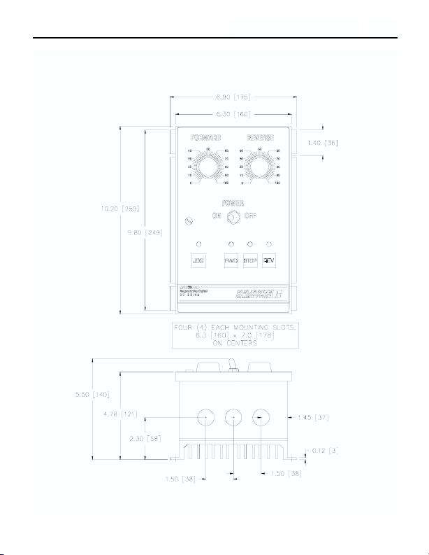
5
Dimensions
Figure 1. DC3RD Dimensions
Page 14

6
Installation
ATTENTION: Only qualified technical personnel,
familiar with the construction and operation of this
equipment and the hazards involved, should install,
adjust, operate and/or service this equipment. Read and
understand this instruction manual in its entirety before
proceeding. Failure to observe this precaution could
result in severe bodily injury or loss of life.
ATTENTION: This equipment is at line voltage when
AC power is connected. Disconnect and lockout all
ungrounded conductors of the AC power line before
working on the unit. Failure to observe this precaution
could result in severe bodily injury or loss of life.
ATTENTION: The user is responsible for conforming
with all applicable local and national codes. Failure to
observe this precaution could result in severe bodily
injury or loss of life.
Page 15

Mounting
NEMA 4X enclosed drives come with three 0.88 inch (22
mm) conduit knockout holes at the bottom of the case. The
units may be vertically wall mounted using the four 0.25
inch (6 mm) slotted holes on the attached heat sink. For
motor loads less than 5 ADC, the drive may be bench
mounted horizontally, or operated without mounting.
1. Install the mounting screws.
2. For access to the terminal strip, turn the slotted screw on
the front cover counterclockwise until it is free from the
case. The right side of the cover is hinged to the case.
Lift or pull the slotted screw to open the case.
3. Carefully remove the conduit knockouts by tapping them
into the case and twisting them off with pliers.
4. Install conduit hardware through the 0.88 inch (22 mm)
conduit holes. Connect external wiring to the terminal
block.
5. Grasp the slotted screw and tilt the front cover back into
place. Avoid pinching any wires between the front cover
and the case.
6. Turn the slotted screw clockwise until tight to secure the
front cover.
7. Set the POWER switch to the OFF position before
applying the AC line voltage.
7Installation
Page 16

8 Installation
Wiring
ATTENTION: This drive is isolated from earth
ground. Circuit potentials are at 115 or 230 VAC above
ground. To prevent the risk of injury or fatality, avoid
direct contact with the printed circuit board or with
circuit elements. Use a non-metallic screwdriver for the
calibration trimpots.
ATTENTION: Do not disconnect any of the motor
leads from the drive unless power is removed or the
drive is disabled. Opening any one motor lead may
destroy the drive.
Use 18-24 AWG wire for speed adjust potentiometer
wiring. Use 14–16 AWG wire for AC line (L1, L2) and
motor (A1 and A2) wiring.
Page 17

Shielding guidelines
9Installation
As a general rule, Reliance Electric recommends shielding
of all conductors if:
• wire lengths exceed 4 inches and power and logic leads
must be bundled together*; or
• radiated and/or conducted noise must be minimized due
to concerns about immunity or general compliance (CE,
FCC, etc.)
* Reliance Electric considers this an unfavorable condition and does
not recommend bundling power and logic leads for any length.
ATTENTION: If it is not practical to shield power
conductors, Reliance Electric recommends shielding all
logic-level leads. If shielding is not practical, use
twisted-pair control wiring to minimize induced noise.
ATTENTION: Under no circumstances should power
and logic leads be bundled together. Induced voltage
can cause unpredictable behavior any electronic device,
including motor controls.
Page 18

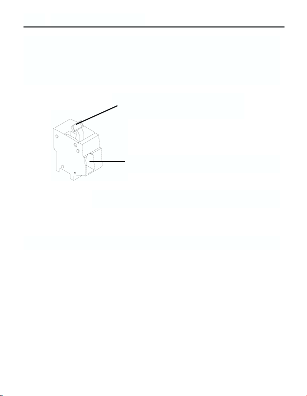
The DC3RD drive has line fuses mounted on fuse holders
501 and 502 (FU501 and FU502). When replacing the line
fuses, use fast acting fuses rated for 250 VAC or higher,
and at least 200% of the armature current. See Table 1 for
recommended line fuse sizes.
10 Installation
It may be necessary to earth ground the shielded cable. If
noise is produced by devices other than the drive, ground
the shield at the drive end. If noise is generated by a device
on the drive, ground the shield at the end away from the
drive. Do not ground both ends of the shield.
If the drive continues to pick up noise after grounding the
shield, it may be necessary to add AC line filtering devices,
or to mount the drive in a less noisy environment.
Heat sinking
The DC3RD contains sufficient heat sinking in its basic
configuration. No additional heat sinking is necessary.
Line fusing
ATTENTION: Most code requires that upstream
branch protection be provided to protect input power
wiring. Failure to observe this precaution could result in
severe bodily injury or loss of life.
Page 19

11Installation
Table 1. Recommended Line Fuse Sizes
90 VDC Motor 180 VDC Motor Max. DC Armature AC Line Fuse
Horsepower Horsepower Current (amps) Size (amps)
1/20 1/10 0.5 3
1/15 1/8 0.8 3
1/8 1/4 1.5 5
1/6 1/3 1.7 5
1/4 1/2 2.6 8
1/3 3/4 3.5 8
1/2 1 5.0 10
3/4 1 1/2 7.6 15
1 2 10 20
Page 20
12 Installation
Cage-clamp terminals
DC3RD Series drive connections are made to cage-clamp
terminals. To insert a wire into a terminal, see Figure 2.
1. Press down on the lever arm
using a small screwdriver.
2. Insert wire into the wire clamp.
3. Release the lever arm to clamp wire.
Figure 2. Cage-Clamp Terminal
Page 21

13Installation
ATTENTION: Do not connect this equipment with
power applied. Failure to heed this directive may result
in fire or serious injury.
Connections
Connect the power input leads and a DC motor to the
drive’s terminal board as shown in Figure 3, page 14.
Ensure that the motor voltage rating is consistent with the
drive’s output voltage.
DC3RD drives supply motor voltage from A1 and A2
terminals. It is assumed throughout this manual that, when
A1 is positive with respect to A2 , the motor will rotate
clockwise (CW) while looking at the output shaft
protruding from the front of the motor. If this is opposite
of the desired rotation, simply reverse the wiring of A1
and A2 with each other.
Page 22

14 Installation
NOTE: TERMINAL 1 IS
HOT. TERMINALS 2 AND 3
ARE NEUTRAL.
Figure 3. Connections
Page 23

15Installation
Field output
The field output is for shunt wound motors only. Do not
make any connections to the field output when using a
permanent magnet motor. See Table 2 for field output
connections.
Table 2. Field Output Connections
Line Voltage Approximate Field Field
(VAC) Voltage (VDC) Connections
115 50 F1 and L1
115 100 F1 and F2
230 100 F1 and L1
230 200 F1 and F2
Page 24

16 Installation
Limit switch connections (optional)
All connections to the
logic board are prewired
(see prewired connections
on page 49). If your
application requires the
use of limit switches,
connect the limit switches
to the logic board as
shown in Figure 4. If only the forward limit switch is used,
remove the reverse limit switch and jumper terminal 21 to
22. If only the reverse limit switch is used, remove the
forward limit switch and jumper terminal 20 to 22.
Remote pushbuttons (optional)
Add external jog, stop, reverse
and forward pushbuttons to
control the drive from a
remote location. Connect
normally open pushbuttons to
top board terminals 15
through 19 (see Figure 5).
Case pushbuttons may still be
used if external pushbuttons
are connected.
Figure 4. Optional limit switch
connections
Figure 5. Optional remote
pushbutton connections
Page 25

17Installation
Slide switches
ATTENTION: Change voltage switch settings only
when the drive is disconnected from AC line voltage.
Make sure both switches are set to their correct
position. If the switches are improperly set to a lower
voltage position, the motor will not run at full voltage
and may cause damage to the transformer. If the
switches are improperly set to a higher voltage position,
the motor will overspeed, which may cause motor
damage, or result in bodily injury or loss of life.
Page 26

18 Installation
Feedback Switch
Set to ARM for armature feedback,
or TACH for tachogenerator
feedback.
Armature Voltage Switch
Set to 90 for 90 VDC motor,
or 180 for 180 VDC motor.
Line Voltage Switches
Set to 115 for 115 VAC line voltage, or
230 for 230 VAC line voltage.
Figure 6. Slide Switch Locations
Page 27

19Installation
Mode select switches
Mode select switches, located on the logic board (see
Figure 7), are preset with switch 1 OFF and switch 2 ON.
This allows you to operate the drive without the use of
limit switches. Change mode select switch settings when
power is off. Make sure that terminals 20, 21, and 22 are
jumpered if limit switches are not used. If limit switches
are used, set the mode select switches to one of the four
operating modes:
Figure 7. Mode Select Switches
Mode Select Switches
Page 28

20 Installation
Mode 1 (1 and 2 OFF) – Half cycle between forward
and reverse limit switches.
Mode 2 (1 ON and 2 OFF) – Single cycle between
forward and reverse limit switches.
Mode 3 (1 OFF and 2 ON) – Continuous cycle
between forward and reverse limit switches.
Mode 4 (1 and 2 ON) – Single cycle with one limit
switch.
See page 24 for more information on limit switch operating
modes.
Operating modes
Page 29

21
Operation
ATTENTION: Only qualified technical personnel,
familiar with the construction and operation of this
equipment and the hazards involved, should install,
adjust, operate and/or service this equipment. Read and
understand this instruction manual in its entirety before
proceeding. Failure to observe this precaution could
result in severe bodily injury or loss of life.
ATTENTION: All adjustments to these components
should be made with power removed. Failure to
observe this precaution could result in severe bodily
injury or loss of life.
ATTENTION: Change voltage switch settings only
when the drive is disconnected from AC line voltage.
Make sure both switches are set to their correct
position. If the switches are improperly set to a lower
voltage position, the motor will not run at full voltage
and may cause damage to the transformer. If the
switches are improperly set to a higher voltage position,
the motor will overspeed, which may cause motor
damage, or result in bodily injury or loss of life.
Page 30

Before applying power
• Verify that no conductive material is present on the
printed circuit board.
• Set all switches to their proper settings.
• Verify that the AC supply is properly balanced.
Startup
1. Set the power switch to OFF; set forward and reverse
speed adjust potentiometers to 0; set FWD JOG and
REV JOG trimpots to 50% (12 o’clock).
2. Apply AC line voltage.
3. Set the power switch to ON. The LED above STOP is
lit.
3. To rotate the motor in the forward direction:
a. Press FWD. The LED above it lights.
b. Set the forward speed adjust potentiometer until the
motor rotates at the desired forward speed.
To rotate the motor in the reverse direction:
a. Press REV. The LED above it lights.
b. Set the reverse speed adjust potentiometer until the
motor rotates at the desired reverse speed.
5. To switch the direction of motor rotation, press the
pushbutton of the opposite direction.
6. Press STOP to stop the motor.
22 Operation
Page 31

Jogging the motor
The DC3RD digital drive has a jog option, allowing you to
jog the motor in the forward or reverse direction as long as
the forward or reverse pushbutton is pressed. The drive can
be switched to the jog mode while the motor is stopped, or
is running in either the forward or reverse direction.
To jog the motor:
1. Press JOG to enter the jog mode.
2. To jog the motor in the forward direction:
a. Press and hold the FWD pushbutton. The motor
jogs in the forward direction. The motor speed is
set by the FWD JOG trimpot.
b. Release FWD to stop the motor.
To jog the motor in the reverse direction:
a. Press and hold the REV pushbutton. The motor jogs
in
the reverse direction. The motor speed is set by the
REV JOG trimpot.
b. Release REV to stop the motor.
3. To exit the jog mode, press STOP.
23Operation
Page 32

24 Operation
Limit switch operating modes
The following is a description of the four limit switch
operating modes.
Mode 1 – Half cycle between forward and reverse
limit switches
1. Press the forward pushbutton for
forward motor rotation.
2. Motor rotates in the forward
direction until the forward limit
switch opens.
3. The motor stops when the forward
limit switch opens.
4. Press the reverse pushbutton for
reverse motor rotation
5. Motor rotates in the reverse
direction until the reverse limit
switch opens.
6. The motor stops when the reverse
limit switch opens. Return to step 1
to repeat the process
Press FWD to go forward.
Reverse
Limit
Switch
Forward
Limit
Switch
Forward Direction
Reverse Direction
STOP
STOP
Press REV to go reverse.
Page 33

25Operation
1. Press the forward pushbutton for
forward motor rotation.
2. Motor rotates in the forward
direction until the forward limit
switch opens.
3. The motor stops and dwells when the
forward limit switch opens. Set the
dwell time by calibrating the DWELL
TIME trimpot (see page 23).
4. Motor rotates in the reverse
direction until the reverse limit
switch opens.
5. The motor stops when the reverse
limit switch opens. Return to step 1
to repeat the process.
Press FWD to go forward.
Reverse
Limit
Switch
Forward
Limit
Switch
Forward Direction
Reverse Direction
STOP
AND
DWELL
STOP
Mode 2 – Single cycle between forward and reverse
limit switches
• Single cycle automatically returns travel to the reverse
limit switch location.
Page 34

26 Operation
Mode 3 – Continuous cycle between forward and
reverse limit switches
1. Press the forward pushbutton for
forward motor rotation.
2. Motor rotates in the forward
direction until the forward limit
switch opens.
3. The motor stops and dwells when
the forward limit switch opens. Set
the dwell time by calibrating the
DWELL TIME trimpot (see page
23).
4. Motor rotates in the reverse
direction until the reverse limit
switch opens.
5. The motor stops and dwells when
the reverse limit switch opens.
The process repeats steps 2-5
until you press the STOP
pushbutton.
Reverse
Limit
Switch
Forward
Limit
Switch
Forward Direction
Reverse Direction
STOP
AND
DWELL
STOP
AND
DWELL
Press FWD to go forward.
Page 35

27Operation
1. Press the forward pushbutton
for forward motor rotation.
OR
Press the reverse pushbutton
for reverse motor rotation.
2. Motor rotates until the limit
switch opens.
3. The motor stops when the
limit switch is open. Return
to step 1 to restart the motor.
Limit Switch
STOP
Press FWD to go forward.
Press REV to go reverse.
Mode4–Singlecycle with one limit switch
IMPORTANT: For all operating modes, press the STOP
pushbutton to stop a rotating motor before a limit switch is
activated. Resume operation by pressing the FORWARD or
REVERSE pushbuttons.
Page 36

28
Calibration
ATTENTION: Dangerous voltages exist on the drive
when it is powered, and up to 30 seconds after power is
removed and the motor stops. When possible,
disconnect the voltage input from the drive before
adjusting the trimpots. If the trimpots must be adjusted
with power applied, use insulated tools and the
appropriate personal protection equipment. BE ALERT.
High voltages can cause serious or fatal injury.
ATTENTION: The control circuit is at line potential
when the drive is energized. Use a non-metallic
screwdriver when making adjustments to the circuit
board potentiometers. Exercise extreme caution as
hazardous voltage exists. Failure to observe these
precautions could result in severe bodily injury or loss
of life.
Page 37

Power board trimpots
MIN SPD
MIN SPD may be calibrated if the CCW side of the speed
adjust potentiometer is connected to S0 (S0 is in series
with the MIN SPD trimpot). Since the forward and reverse
speed adjust potentiometers are not connected to S0, MIN
SPD cannot be calibrated.
MAX SPD
The MAX SPD trimpot setting determines the motor speed
when the forward (or reverse) speed adjust potentiometer is
turned full CW. It is factory set for maximum rated speed.
To calibrate MAX SPD:
1. Set the MAX SPD trimpot full CCW.
2. Press FWD (or REV).
3. Turn the forward (or reverse) speed adjust
potentiometer full CW.
4. Adjust the MAX SPD trimpot until the desired
maximum motor speed is reached.
The calibrated maximum speed is the same for both
forward and reverse directions.
29Calibration
Page 38

FWD ACC
The FWD ACC trimpot setting determines the time the
motor takes to ramp to either a higher speed in the forward
direction or a lower speed in the reverse direction, within
the limits of available torque. FWD ACC is factory set for
its fastest forward acceleration time.
Turn the FWD ACC trimpot CW to increase the forward
acceleration time and reverse deceleration time, and CCW
to decrease the forward acceleration time and reverse
deceleration time.
REV ACC
The REV ACC trimpot setting determines the time the
motor takes to ramp to either a higher speed in the reverse
direction or a lower speed in the forward direction, within
the limits of available torque. REV ACC is factory set for
its fastest reverse acceleration time.
Turn the REV ACC trimpot CW to increase the reverse
acceleration time and forward deceleration time, and CCW
to decrease the reverse acceleration time and forward
deceleration time.
30 Calibration
Page 39

IR COMP
The IR COMP trimpot setting determines the degree to
which motor speed is held constant as the motor load
changes. It is factory set for optimum motor regulation. See
Figure 8, page 40, for recommended IR COMP trimpot
settings.
To calibrate IR COMP (exact calibration):
1. With the motor rotating in the forward direction, set the
forward speed adjust potentiometer until the motor runs
at midspeed (for example, 900 RPM for an 1800 RPM
motor).
2. Load the motor armature to its full load armature
current rating. The motor should slow down.
3. While keeping the load on the motor, rotate the IR
COMP trimpot until the motor runs at the speed
measured in step 1.
Approximate calibration:
If the motor does not maintain set speed as the load
changes, gradually rotate the IR COMP trimpot CW. If the
motor oscillates (overcompensation), the IR COMP trimpot
may be set too high (CW). Turn the IR COMP trimpot
CCW to stabilize the motor speed.
31Calibration
Page 40

32 Calibration
FWD TQ
ATTENTION: Although the FWD TQ trimpot is set to
120% of motor nameplate current rating, continuous operation
beyond that rating may damage the motor.
The FWD TQ setting determines the maximum torque for
accelerating and driving the motor in the forward direction.
It also sets the maximum torque for decelerating the motor
from the reverse direction. FWD TQ is factory set at 120%
of rated motor current.
To recalibrate FWD TQ, refer to the recommended FWD
TQ settings on Figure 8, page 40, or recalibrate using the
following procedure:
1. With the power disconnected from the drive, connect a
DC ammeter in series with the armature.
2. Set the FWD TQ trimpot to minimum (full CCW).
3. Lock the motor armature. Be sure that the motor is
firmly mounted.
4. Connect power to the drive. The motor should remain
stopped.
5. Press FWD .
Page 41

6. Set the forward speed adjust potentiometer for maximum
forward speed.
7. Adjust the FWD TQ trimpot CW until the armature
current is 120% of motor rated current.
8. Set the forward speed adjust potentiometer to minimum
and remove the stall from the motor.
33Calibration
REV TQ
ATTENTION: Although the REV TQ trimpot is set to
120% of motor nameplate current rating, continuous operation
beyond that rating may damage the motor.
The REV TQ trimpot setting determines the maximum
torque for accelerating and driving the motor in the reverse
direction. It also sets the maximum torque for decelerating
the motor from the forward direction. REV TQ is factory
set at 120% of rated motor current.
To recalibrate REV TQ, refer to the recommended REV
TQ settings on Figure 8, page 40, or recalibrate using the
following procedure:
1. With the power disconnected from the drive, connect a
DC ammeter in series with the armature.
Page 42

34 Calibration
ATTENTION: Do not turn DB past the 60 HZ setting.
This could cause shoot through, which may blow fuses
and cause the drive to fail.
DB
The deadband trimpot setting determines the time that will
elapse between the application of current in one direction
before current is applied in the opposite direction. It also
affects the resistance that a motor has to changes in shaft
position at zero speed by applying AC voltage to the motor
armature.
2. Set the REV TQ trimpot to minimum (full CCW).
3. Lock the motor armature. Be sure that the motor is
firmly mounted.
4. Connect power to the drive. The motor should remain
stopped.
5. Press REV .
5. Set the reverse speed adjust potentiometer for maximum
reverse speed.
6. Adjust the REV TQ trimpot CW until the armature
current is 120% of motor rated current.
7. Set the reverse speed adjust potentiometer to minimum
and remove the stall from the motor.
Page 43

Deadband is factory calibrated to approximately the 3
o’clock position for 60 Hz AC line operation. Recalibrate
the deadband to the 9 o’clock position for 50 Hz AC line
operation. If you hear motor noise (a humming or buzzing
sound), the deadband might be set too high. Turn the
deadband trimpot CCW until the motor noise ceases. See
Figure 9, page 40, for recommended deadband settings.
35Calibration
Page 44

36 Calibration
IMPORTANT: Calibrate the TACH trimpot setting only
when a tachogenerator is used.
The TACH setting, like the IR COMP setting, determines
the degree to which motor speed is held constant as the
motor load changes.
TACH (for use with tachogenerator feedback only)
ATTENTION: Applying the incorrect polarity to the
tachogenerator can cause an overspeed condition. Make
sure the positive (+) wire is connected to terminal T1
and the negative (-) wire is connect to terminal T2 when
the motor is running in the forward direction. Failure to
observe this precaution could result in bodily injury.
ATTENTION: The control circuit is at line potential
when the drive is energized. Use a non-metallic
screwdriver when making adjustments to the circuit
board potentiometers. Exercise extreme caution as
hazardous voltage exists. Failure to observe these
precautions could result in severe bodily injury of loss
of life.
Page 45

To calibrate the TACH:
1. Connect the tachogenerator to T1 and T2. The polarity is
“+” for T1 and “–” for T2 when the motor is running in
the forward direction.
2. Set switch 504 (SW504) to ARM for armature feedback.
3. Set the power switch to ON.
4. Press FWD .
3. Set the forward speed adjust potentiometer full CW.
Measure the armature voltage across A1 and A2 using a
voltmeter.
4. Set the speed adjust potentiometer to 0 (zero speed).
5. Set SW504 to TACH for tachogenerator feedback.
6. Set the IR COMP trimpot full CCW.
7. Set the TACH trimpot full CW.
8. Set the speed adjust potentiometer full CW.
9. Adjust the TACH trimpot until the armature voltage is
the same value as the voltage measured in step 3.
Check that the tachogenerator is properly calibrated. The
motor should run at the same set speed when SW504 is set
to either armature or tachogenerator feedback.
37Calibration
Page 46

Logic board trimpots
FWD JOG
The FWD JOG trimpot setting determines the motor speed
when it rotates in the forward direction in the jog mode. To
calibrate FWD JOG:
1. Press JOG .
2. Press and hold the FWD pushbutton. The motor jogs in
the forward direction.
3. Adjust the FWD JOG trimpot until the motor rotates at
the desired forward jog speed.
4. Release FWD to stop the motor.
REV JOG
The REV JOG trimpot setting determines the motor speed
when it rotates in the reverse direction in the jog mode. To
calibrate REV JOG:
1. Press JOG .
2. Press and hold the REV pushbutton. The motor jogs in
the reverse direction.
3. Adjust the REV JOG trimpot until the motor rotates at
the desired reverse jog speed.
4. Release REV to stop the motor.
38 Calibration
Page 47

DWELL TIME
The DWELL TIME trimpot setting determines the length
of time the motor stops before rotating in the opposite
direction. DWELL TIME only works when the drive is set
for Mode 2 and Mode 3 (see page 24 for limit switch
operating modes).
There are 10 DWELL TIME settings (0 thru 9). Set the
DWELL TIME to 0 (the factory setting) for 0.1 second
delay. Increasing the setting one increment higher adds 0.1
second to the dwell time. Set the DWELL TIME trimpot to
9 for approximately 1 second delay.
39Calibration
Page 48

40 Calibration
Figure 8. Recommended FWD TQ, REV TQ,
and IR COMP Settings for DC3RD
(actual settings may vary with each application)
Figure 9. Deadband Settings
Page 49

41
Troubleshooting
ATTENTION: This equipment is at line voltage when
AC power is connected. Disconnect and lockout all
ungrounded conductors of the AC power line before
working on the unit. Failure to observe this precaution
could result in severe bodily injury or loss of life.
Page 50

Before applying power:
Check the following steps before proceeding:
1. The AC line voltage must be balanced, and match the
voltage on the drive nameplate.
2. Check that all switches are set to the correct positions.
3. The deadband (DB) trimpot must be set approximately
at the 3 o’clock position for 60 Hz AC line frequency or
at 9 o’clock for 50 Hz AC line frequency.
4. The motor must be rated for the drive’s rated armature
(all motors) and field outputs (shunt wound motors
only).
5. Do not make any connections to F1 and F2 if using a
permanent magnet motor.
6. Terminal block connections should be consistent with
the connections shown in this manual.
7. Check that line fuses FU501 and FU502 are properly
sized and not blown.
42 Troubleshooting
Page 51

43Troubleshooting
Problem Possible
Causes
Suggested
Solutions
Line fuse blows 1. Line fuses are the
wrong size.
2. Motor cable or
armature is shorted
to ground.
3. Nuisance tripping
caused by a
combination of
ambient conditions
and high-current
spikes
(i.e. reversing).
4. Field circuit is
open.
1. Check that line
fuses are properly
sized.
2. Check motor cable
and armature for
shorts.
3. Add a blower to
cool the drive
components;
decrease FWD TQ
and REV TQ settings;
check wiring to be
sure noise is reduced
or eliminated.
4. Send in drive to
Reliance Electric
repair department.
Page 52

44 Troubleshooting
Problem Possible
Causes
Suggested
Solutions
Line fuse does not
blow, but the motor
does not run when
the forward or
reverse pushbutton
is pressed
1. Forward or
reverse speed
adjust potentiometer
is set to zero speed.
2. Forward or
reverse speed
adjust potentiometer
is not connected to
drive input properly;
connections are
open.
3. Middle and right
INH-RUN terminals
are not jumpered.
4. INHIBIT terminals
are jumpered.
5. S2 is shorted to
S0.
6. Drive is in current
limit.
1. Increase the
forward or reverse
speed adjust
potentiometer setting
2. Check connections
to input. Verify that
connections are not
open.
3. Jumper middle and
right INH-RUN
terminals.
4. Remove jumper
from INHIBIT
terminal.
5. Remove short.
6. Verify if motor is
jammed. Increase
FWD TQ or REV TQ
setting if they are set
too low.
Page 53

45Troubleshooting
Problem Possible
Causes
Suggested
Solutions
Line fuse does not
blow, but the motor
does not run when
the forward or
reverse pushbutton
is pressed (cont.)
Motor runs too slow
or too fast
7. Drive is not
receiving AC line
voltage.
8. Motor is not
connected.
9. Touch panel, logic
board, or power
board connections
might be loose.
1. Switches set
incorrectly.
2. MAX SPD is not
calibrated.
3. Motor field not
properly connected
(shunt wound
motors only)
7. Apply AC line
voltage to L1 and L2.
8. Connect motor to
A1 and A2.
9. Check all
connections.
1. Verify all switch
settings.
2. Calibrate MAX
SPD.
3. Verify motor field
connections.
Page 54

46 Troubleshooting
Problem Possible
Causes
Suggested
Solutions
Motor runs too fast
at maximum speed
setting
Motor will not reach
the desired speed
Motor pulsates or
surges under load
1. MAX SPD setting
is too high.
2. Motor field
connections are
loose (shunt wound
motors only).
1. MAX SPD setting
is too low.
2. IR COMP setting
is too low.
3. Motor is
overloaded.
1. IR COMP is set
too high.
2. Motor “bouncing”
in and out of torque
limit.
1. Recalibrate MAX
SPD.
2. Check motor field
connections.
1. Increase MAX
SPD setting.
2. Increase the IR
COMP setting.
3. Check motor load.
Resize the motor if
necessary.
1. Adjust the IR
COMP setting slightly
CCW until the motor
speed stabilizes.
2. Make sure motor is
not undersized for
load; adjust FWD TQ
and REV TQ
trimpots.
Page 55

47Troubleshooting
Problem Possible
Causes
Suggested
Solutions
Motor does not
reverse
Motor makes a
humming or buzzing
noise
FWD or REV JOG
speed is too slow or
too fast
Touch panel, logic
board, or power
board connections
might be loose.
Deadband setting is
too high.
FWD or REV JOG
speed not
calibrated.
Check all
connections.
Turn deadband (DB)
trimpot CCW until the
noise stops.
Calibrate FWD JOG
and REV JOG
trimpots (see
Calibration section).
Page 56

48 Troubleshooting
Figure 10. DC3RD Block Diagram
Block Diagram
Page 57

49Troubleshooting
Prewired Connections
Figure 11. Prewired Connections to L1, L2 (115) and L2 (230)
Page 58

50 Troubleshooting
Figure 12. Touch Panel, Logic Board,
and Power Board Connections
Page 59

Most non-regenerative, variable-speed DC drives control
current flow to a motor in one direction. The direction of
current flow is the same direction as the motor rotation.
Non-regenerative drives operate in Quadrant 1, and also in
Quadrant 3 if the drive is reversible (see Figure 13,
page 52). Motors must stop before reversing direction.
Unless dynamic braking is used, non-regenerative drives
cannot oppose an overhauling load, and cannot decelerate a
load faster than coasting to a lower speed.
Regenerative drives operate in two additional quadrants:
Quadrant 2 and Quadrant 4. In these quadrants, motor
torque is in the opposite direction of motor rotation.
Regenerative drives can reverse a motor without
contactors, switches, brake resistors, or inhibit plugs. They
can also control an overhauling load and decelerate a load
faster than it would take to coast to a lower speed.
51
Regenerative Drives
Page 60

52 Regenerative Drives
Figure 13. Four Quadrant Operation
Page 61

Reliance Electric Corporation hereby certifies that its
DC3RD drive has been approved to bear the “CE” mark
provided the conditions of approval have been met by the
end user.
The DC3RD has been tested to the following test
specifications:
EN55011:1991 (emissions), and
EN50082-1:1992 (immunity)
Compliance allows the DC3RD to bear the CE mark.
The end user, as described herein, falls into one of two
categories:
1. The Consumer will deploy a stand-alone unit as an
integral, yet external, portion of the machine being
operated.
2. The Original Equipment Manufacturer (OEM) will
implement the product as a component of the
machine being manufactured.
53
CE Compliance
Page 62

AC Line Filters
In addition to EMI/RFI safeguards inherent in the DC3RD
design, external filtering is required. Reliance Electric
requires the Corcom® AC line filters listed in Table 3. Use
model 5VR1 with drives rated for 3 ADC or below, and
model 20VV1 with drives rated for 10 ADC or below.
Table 3. AC Line Filters
Corcom®Model Number 5VR1 20VV1
Rated Current 5 A 20 A
Inductance 1.032 mH 0.88 mH
Capacitance
Line to Line 0.303 µF 0.303 µF
Line to Ground 0.011 µF 0.011 µF
Discharge Resistor 680 KΩ 680 KΩ
Wire the AC line filter within 0.25 meters of the drive. The
ground connection from the filter must be wired to solid
earth ground (resistance less than 500 ohms); not machine
ground. This is very important!
If the end-user is using a CE-approved motor, the correct
filter from Table 3 is all that is necessary to meet the
EMC directives listed herein.
54 CE Compliance
Page 63

Armature Filters
If the end-user is not using a CE-approved motor, a filter
on the armature must also be used. See Table 4 for
recommended armature filters. Use model CE04RG with
drives rated for 3 ADC or below, and model CE10RG with
drives rated for 10 ADC or below.
Table 4. Armature Filters
Reliance Electric®Model Number CE04RG CE10RG
Rated Current 4 A 10 A
Inductance 1200 mH 1200 mH
Capacitance (C1 and C2) @ 400W VDC
0.1 µF 0.1 µF
Discharge Resistor 680KΩ 680KΩ
Wire the armature filter to the DC output of the drive, as
close to the drive as possible. The ground connection from
the filter must be wired to solid earth ground (resistance
less than 500 ohms); not machine ground. This is very
important!
55CE Compliance
Page 64

The end user must use the filtration listed in this addendum
to comply with CE. The OEM may choose to provide
alternative filtering that encompasses the Reliance Electric
drive and other electronics within the same panel.The
OEM has this liberty because CE is a machinery directive.
Whether or not every component in the OEM’s machinery
meets CE, the OEM must still submit his machine for CE
approval. Thus, no component must necessarily meet CE
within the machine, as long as the OEM takes the
necessary steps to guarantee the machine does meet CE. By
the same token, even if every component in the OEM’s
machine does meet CE, the machine will not necessarily
meet CE as a machine.
Using CE-approved wiring practices (like proper shielding)
and the filters should assure the drive will meet EN55014
(1993 emissions standard) and EN50082-1 (1992 immunity
standard).
56 CE Compliance
Page 65

Notes
Page 66

Notes
Page 67

Page 68

U.S. Drives Technical Support
Tel: (1) 262.512.8176, Fax: (1) 262.512.2222, Email: support@drives.ra.rockwell.com, Online: www.ab.com/support/abdrives
Publication D2-3455-April 2000 Copyright © 2000 Rockwell Automation, Inc. All Rights Reserved. Printed in USA.
 Loading...