

Page 1

SCADA System
Application Guide
Page 2
Important User Information
Solid state equipment has operational characteristics differing from those of
electromechanical equipment. Safety Guidelines for the Application,
Installation and Maintenance of Solid State Controls (Publication SGI-1.1
available from your local Rockwell Automation
http://www.ab.com/manuals/gi) describes some important differences
between solid state equipment and hard-wired electromechanical devices.
Because of this difference, and also because of the wide variety of uses for
solid state equipment, all persons responsible for applying this equipment
must satisfy themselves that each intended application of this equipment is
acceptable.
In no event will Rockwell Automation, Inc. be responsible or liable for
indirect or consequential damages resulting from the use or application of
this equipment.
The examples and diagrams in this manual are included solely for illustrative
purposes. Because of the many variables and requirements associated with
any particular installation, Rockwell Automation, Inc. cannot assume
responsibility or liability for actual use based on the examples and diagrams.
No patent liability is assumed by Rockwell Automation, Inc. with respect to
use of information, circuits, equipment, or software described in this manual.
Reproduction of the contents of this manual, in whole or in part, without
written permission of Rockwell Automation, Inc. is prohibited.
Throughout this manual we use notes to make you aware of safety
considerations.
®
sales office or online at
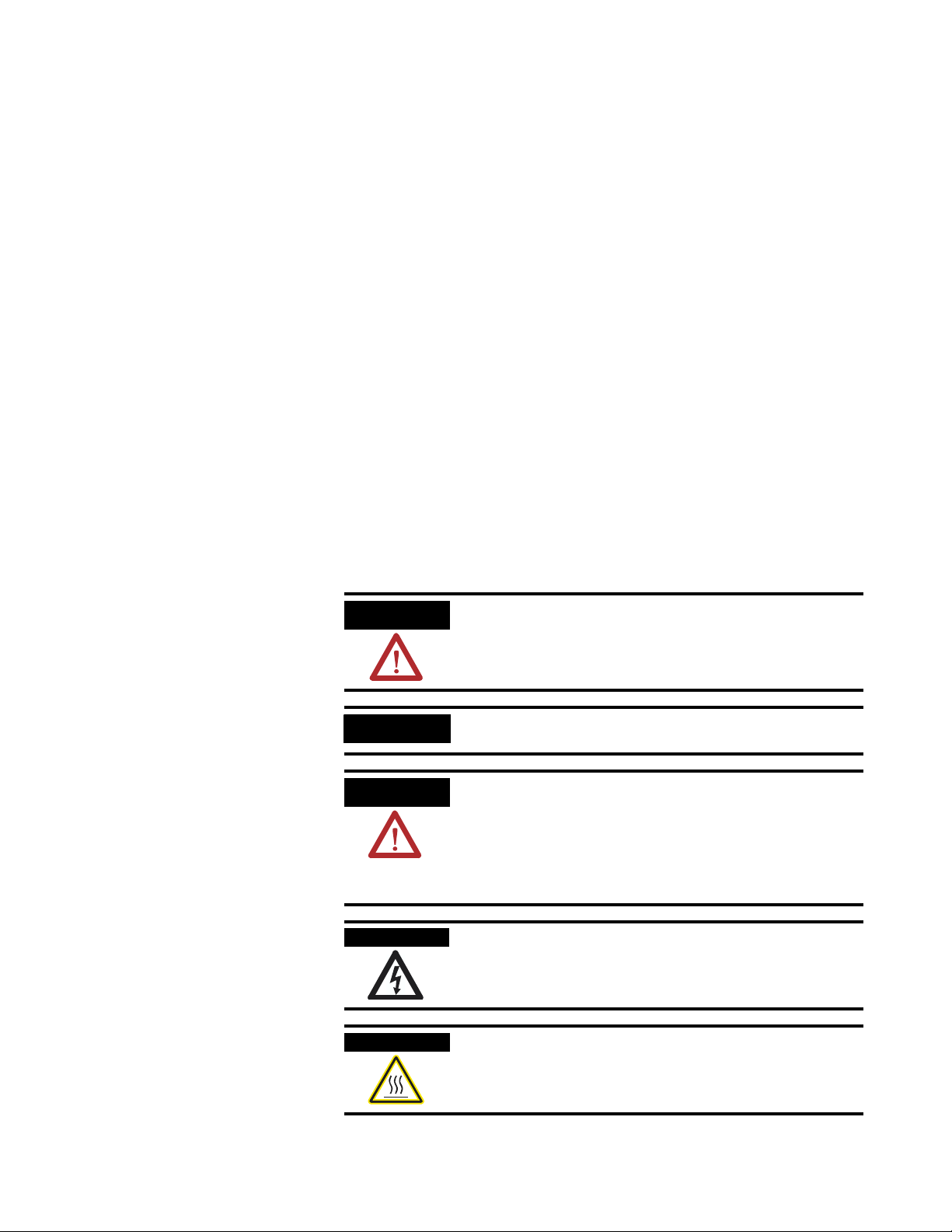
WARNING
IMPORTANT
ATTENTION
SHOCK HAZARD
BURN HAZARD
Identifies information about practices or circumstances
that can cause an explosion in a hazardous environment,
which may lead to personal injury or death, property
damage, or economic loss.
Identifies information that is critical for successful
application and understanding of the product.
Identifies information about practices or circumstances
that can lead to personal injury or death, property
damage, or economic loss. Attentions help you:
• identify a hazard
• avoid a hazard
• recognize the consequence
Labels may be located on or inside the drive to alert
people that dangerous voltage may be present.
Labels may be located on or inside the drive to alert
people that surfaces may be dangerous temperatures.
Page 3

Summary of Changes
The information below summarizes the changes to this manual since
the last printing.
To help you find new and updated information in this release of the
manual, we have included change bars as shown to the right of this
paragraph.
For information on See
Removing Configuring Classic PLC-5 Processors with
1785-KE Modules chapter
Add in additional publications Preface
Designing communication for DF1 Radio Modem 1-17 through 1-19
Modbus RTU 3-46 through 3-57
Data Logging 3-58 through 3-69
Conditions that will erase the data retrieval file 3-69
DF1 Radio Modem 4-7 through 4-8
Configuring a Radio Modem station 4-27 through 4-32
Rockwell Automation modems 8-3 through 8-4
Configuring modems for PLC-5, SLC, and Logix processors 10-3
Configuring modems for MicroLogix 1100/1200/1500
controllers
Communicating over the telephone line 10-4 through 10-8
Remotely programming Allen-Bradley processors over a
telemetry network
DF1 Radio Modem B-7
Third party suppliers Appendix C
NA
10-4
Chapter 11
1 Publication AG-UM008C-EN-P - February 2005
Page 4

2 Summary of Changes
Publication AG-UM008C-EN-P - February 2005
Page 5

Designing Communication
Table of Contents
Preface
What SCADA Information Is Available?. . . . . . . . . . . . . . . . 1-1
Audience . . . . . . . . . . . . . . . . . . . . . . . . . . . . . . . . . . . . . 1-1
Contents of this Manual. . . . . . . . . . . . . . . . . . . . . . . . . . . 1-2
Terms. . . . . . . . . . . . . . . . . . . . . . . . . . . . . . . . . . . . . . . . 1-3
Address Conventions. . . . . . . . . . . . . . . . . . . . . . . . . . . . . 1-3
Addresses . . . . . . . . . . . . . . . . . . . . . . . . . . . . . . . . . . 1-3
Related Publications . . . . . . . . . . . . . . . . . . . . . . . . . . . . . 1-4
Chapter 1
Chapter Objectives . . . . . . . . . . . . . . . . . . . . . . . . . . . . . . 1-1
Choosing a Polling Mode for DF1 Half-Duplex Master . . . . 1-2
Message-Based Polling Mode . . . . . . . . . . . . . . . . . . . . 1-2
Standard Polling Mode . . . . . . . . . . . . . . . . . . . . . . . . . 1-3
About Polled Report-by-Exception . . . . . . . . . . . . . . . . 1-4
About Slave-to-Slave Messaging . . . . . . . . . . . . . . . . . . 1-5
Addressing Tips . . . . . . . . . . . . . . . . . . . . . . . . . . . . . 1-6
Communication Scheme Design Using Standard-Mode . . . . 1-8
Designing a Polling Scheme . . . . . . . . . . . . . . . . . . . . 1-11
Planning for Timing Issues . . . . . . . . . . . . . . . . . . . . . 1-13
Design Considerations . . . . . . . . . . . . . . . . . . . . . . . . . 1-13
Communication Scheme Design Using
Message-Based Mode . . . . . . . . . . . . . . . . . . . . . . . . . . . . 1-15
Designing Communication
for DF1 Full-Duplex Protocol. . . . . . . . . . . . . . . . . . . . . . . 1-16
Designing Communication for DF1 Radio Modem Protocol. 1-17
Determining When to Use DF1 Radio Modem Protocol . 1-17
What to Do Next? . . . . . . . . . . . . . . . . . . . . . . . . . . . . . . . 1-19
Chapter 2
Configuring Enhanced PLC-5
Processors
1 Publication AG-UM008C-EN-P - February 2005
Chapter Objectives . . . . . . . . . . . . . . . . . . . . . . . . . . . . . . 2-1
Overview . . . . . . . . . . . . . . . . . . . . . . . . . . . . . . . . . . . . . 2-1
Installing the Processor . . . . . . . . . . . . . . . . . . . . . . . . . . . 2-2
Configuring a DF1 Half-Duplex Standard Mode
Master Station . . . . . . . . . . . . . . . . . . . . . . . . . . . . . . . . . . 2-3
Define the Communication Driver Characteristics . . . . . 2-5
Displaying System (Master) Channel Status . . . . . . . . . . 2-7
Create Station Lists. . . . . . . . . . . . . . . . . . . . . . . . . . . . 2-8
Monitor Active Stations . . . . . . . . . . . . . . . . . . . . . . . . 2-10
Configuring a DF1 Half-Duplex Message-based
Mode Master Station . . . . . . . . . . . . . . . . . . . . . . . . . . . . . 2-11
Configuring the Processor as a Slave Station. . . . . . . . . . . . 2-15
Displaying Slave System Channel Status . . . . . . . . . . . . 2-18
Page 6

2 Table of Contents
Configuring MicroLogix
1100/1200/1500 Controllers
Configuring the Processor as a Station on a
Point-to-Point Link . . . . . . . . . . . . . . . . . . . . . . . . . . . . . . 2-20
Displaying Point-to-Point System Channel Status . . . . . . 2-22
Messaging. . . . . . . . . . . . . . . . . . . . . . . . . . . . . . . . . . . . . 2-23
Master Station to Slave Station . . . . . . . . . . . . . . . . . . . 2-23
Polled Report-by-Exception . . . . . . . . . . . . . . . . . . . . . 2-23
Processor-to-Processor . . . . . . . . . . . . . . . . . . . . . . . . . 2-24
Considerations When Configuring MSG Control Blocks . 2-25
Example MSG Control Blocks. . . . . . . . . . . . . . . . . . . . 2-26
Chapter 3
Chapter Objectives . . . . . . . . . . . . . . . . . . . . . . . . . . . . . . 3-1
Overview . . . . . . . . . . . . . . . . . . . . . . . . . . . . . . . . . . . . . 3-2
Installing the Controller. . . . . . . . . . . . . . . . . . . . . . . . . . . 3-2
MicroLogix 1200/1500 Channel 0 Cable Pinouts - User
Supplied Optical Isolator . . . . . . . . . . . . . . . . . . . . . . . 3-3
MicroLogix 1200/1500 Channel 0 Cable Pinouts -
Allen-Bradley Supplied Optical Isolator. . . . . . . . . . . . . 3-4
MicroLogix 1500 LRP Channel 1 Cable Pinouts . . . . . . . 3-5
Using Modems that Support DF1 Communication Protocols 3-6
Dial-up Phone Modems . . . . . . . . . . . . . . . . . . . . . . . . 3-6
Leased-Line Modems . . . . . . . . . . . . . . . . . . . . . . . . . . 3-7
Radio Modems. . . . . . . . . . . . . . . . . . . . . . . . . . . . . . . 3-7
Line Drivers. . . . . . . . . . . . . . . . . . . . . . . . . . . . . . . . . 3-7
Modem Control Line Operation . . . . . . . . . . . . . . . . . . . . . 3-8
DF1 Full-Duplex . . . . . . . . . . . . . . . . . . . . . . . . . . . . . 3-8
DF1 Half-Duplex Slave. . . . . . . . . . . . . . . . . . . . . . . . . 3-8
DF1 Half Duplex Master. . . . . . . . . . . . . . . . . . . . . . . . 3-9
DF1 Radio Modem. . . . . . . . . . . . . . . . . . . . . . . . . . . . 3-9
Configuring DF1 Half-Duplex Channel 0 Parameters. . . . . . 3-11
RTS Send Delay and RTS Off Delay . . . . . . . . . . . . . . . 3-11
Configuring a Standard-Mode DF1 Half-Duplex
Master Station . . . . . . . . . . . . . . . . . . . . . . . . . . . . . . . . . . 3-12
Minimum DF1 Half-Duplex Master Channel 0
ACK Timeout. . . . . . . . . . . . . . . . . . . . . . . . . . . . . . . . 3-14
Determining Minimum Master ACK Timeout . . . . . . . . . 3-15
DF1 Half-Duplex Master Channel Status . . . . . . . . . . . . 3-17
Monitor Active Stations. . . . . . . . . . . . . . . . . . . . . . . . . 3-18
Configuring a Message-based Mode DF1
Half-Duplex Master Station . . . . . . . . . . . . . . . . . . . . . . . . 3-19
Configuring a Slave Station . . . . . . . . . . . . . . . . . . . . . . . . 3-22
Configuring Poll Timeout . . . . . . . . . . . . . . . . . . . . . . . . . 3-25
DF1 Half-Duplex Slave Channel Status . . . . . . . . . . . . . 3-25
Configuring a Radio Modem Station. . . . . . . . . . . . . . . . . . 3-27
DF1 Radio Modem Channel Status . . . . . . . . . . . . . . . . 3-30
Configuring the Store & Forward Table. . . . . . . . . . . . . 3-31
Publication AG-UM008C-EN-P - February 2005
Page 7

Table of Contents 3
Configuring a Station on a Point-to-Point Link . . . . . . . . . . 3-33
DF1 Full-Duplex Channel Status . . . . . . . . . . . . . . . . . . 3-35
DF1 Messaging . . . . . . . . . . . . . . . . . . . . . . . . . . . . . . . . . 3-36
Master Station to Slave Station . . . . . . . . . . . . . . . . . . . 3-36
Polled Report-by-Exception . . . . . . . . . . . . . . . . . . . . . 3-36
Processor-to-Processor . . . . . . . . . . . . . . . . . . . . . . . . . 3-37
Considerations When Configuring MSG
Control Blocks. . . . . . . . . . . . . . . . . . . . . . . . . . . . . . . 3-37
Example MSG Control Blocks . . . . . . . . . . . . . . . . . . . . . . 3-42
Modbus RTU Protocol . . . . . . . . . . . . . . . . . . . . . . . . . . . . 3-46
Modbus RTU Master. . . . . . . . . . . . . . . . . . . . . . . . . . . 3-46
Modbus RTU Slave. . . . . . . . . . . . . . . . . . . . . . . . . . . . 3-47
Modbus RTU Master Configuration . . . . . . . . . . . . . . . . 3-48
Modbus RTU Master Configuration . . . . . . . . . . . . . . . . 3-49
Modbus RTU Slave Configuration . . . . . . . . . . . . . . . . . 3-50
Modbus Slave Memory Map . . . . . . . . . . . . . . . . . . . . . 3-51
Modbus Commands . . . . . . . . . . . . . . . . . . . . . . . . . . . 3-53
Modbus Error Codes . . . . . . . . . . . . . . . . . . . . . . . . . . 3-54
Configuring a Modbus Message . . . . . . . . . . . . . . . . . . 3-56
Data Logging . . . . . . . . . . . . . . . . . . . . . . . . . . . . . . . . . . 3-58
Queues and Records . . . . . . . . . . . . . . . . . . . . . . . . . . 3-58
Example Queue 0 . . . . . . . . . . . . . . . . . . . . . . . . . . . . 3-59
Example Queue 5 . . . . . . . . . . . . . . . . . . . . . . . . . . . . 3-60
Configuring Data Log Queues . . . . . . . . . . . . . . . . . . . 3-62
DLG - Data Log Instruction. . . . . . . . . . . . . . . . . . . . . . 3-64
Data Log Status File . . . . . . . . . . . . . . . . . . . . . . . . . . . 3-64
Retrieving (Reading) Records . . . . . . . . . . . . . . . . . . . . 3-66
Accessing the Retrieval File . . . . . . . . . . . . . . . . . . . . . 3-67
Retrieval Tools. . . . . . . . . . . . . . . . . . . . . . . . . . . . . . . 3-67
Information for Creating Your Own Application . . . . . . 3-68
Conditions that Will Erase the Data Retrieval File . . . . . . . . 3-69
Configuring SLC 5/03, 5/04, and
5/05 Processors
Chapter 4
Chapter Objectives . . . . . . . . . . . . . . . . . . . . . . . . . . . . . . 4-1
Overview . . . . . . . . . . . . . . . . . . . . . . . . . . . . . . . . . . . . . 4-2
Installing the Processor . . . . . . . . . . . . . . . . . . . . . . . . . . . 4-2
Using Modems that Support DF1 Communication Protocols 4-3
Dial-up Phone Modems . . . . . . . . . . . . . . . . . . . . . . . . 4-3
Leased-Line Modems . . . . . . . . . . . . . . . . . . . . . . . . . . 4-3
Radio Modems. . . . . . . . . . . . . . . . . . . . . . . . . . . . . . . 4-4
Line Drivers. . . . . . . . . . . . . . . . . . . . . . . . . . . . . . . . . 4-4
Modem Control Line Operation . . . . . . . . . . . . . . . . . . . . . 4-5
DF1 Full-Duplex . . . . . . . . . . . . . . . . . . . . . . . . . . . . . 4-5
DF1 Half-Duplex Slave. . . . . . . . . . . . . . . . . . . . . . . . . 4-6
DF1 Half Duplex Master. . . . . . . . . . . . . . . . . . . . . . . . 4-6
DF1 Radio Modem. . . . . . . . . . . . . . . . . . . . . . . . . . . . 4-7
Publication AG-UM008C-EN-P - February 2005
Page 8

4 Table of Contents
Configuring DF1 Half-Duplex Channel 0 Parameters. . . . . . 4-8
RTS Send Delay and RTS Off Delay . . . . . . . . . . . . . . . 4-8
Configuring a Standard-Mode DF1 Half-Duplex
Master Station . . . . . . . . . . . . . . . . . . . . . . . . . . . . . . . . . 4-10
Minimum DF1 Half-Duplex Master Channel 0
ACK Timeout. . . . . . . . . . . . . . . . . . . . . . . . . . . . . . . . 4-13
Determining Minimum Master ACK Timeout . . . . . . . . . 4-14
DF1 Half-Duplex Master Channel Status . . . . . . . . . . . . 4-16
Monitor Active Stations. . . . . . . . . . . . . . . . . . . . . . . . . 4-17
Configuring a Message-based Mode DF1 Half-Duplex
Master Station . . . . . . . . . . . . . . . . . . . . . . . . . . . . . . . . . . 4-18
Configuring a Slave Station . . . . . . . . . . . . . . . . . . . . . . . . 4-22
Configuring Channel 0 Poll Timeout . . . . . . . . . . . . . . . . . 4-25
DF1 Half-Duplex Slave Channel Status . . . . . . . . . . . . . 4-25
Configuring a Radio Modem Station. . . . . . . . . . . . . . . . . . 4-27
DF1 Radio Modem Channel Status . . . . . . . . . . . . . . . . 4-30
Configuring the Store & Forward Table. . . . . . . . . . . . . 4-31
Configuring a Station on a Point-to-Point Link . . . . . . . . . . 4-33
DF1 Full-Duplex Channel Status . . . . . . . . . . . . . . . . . . 4-35
Messaging. . . . . . . . . . . . . . . . . . . . . . . . . . . . . . . . . . . . . 4-37
Master Station to Slave Station . . . . . . . . . . . . . . . . . . . 4-37
Polled Report-by-Exception . . . . . . . . . . . . . . . . . . . . . 4-37
Processor-to-Processor . . . . . . . . . . . . . . . . . . . . . . . . . 4-38
Considerations When Configuring MSG
Control Blocks. . . . . . . . . . . . . . . . . . . . . . . . . . . . . . . 4-38
Example MSG Control Blocks . . . . . . . . . . . . . . . . . . . . . . 4-43
Configuring SLC 500 Processors
with 1747-KE Interface Modules
Publication AG-UM008C-EN-P - February 2005
Chapter 5
Chapter Objectives . . . . . . . . . . . . . . . . . . . . . . . . . . . . . . 5-1
Overview . . . . . . . . . . . . . . . . . . . . . . . . . . . . . . . . . . . . . 5-1
Installing the Processor . . . . . . . . . . . . . . . . . . . . . . . . . . . 5-2
Installing the 1747-KE
Interface Module. . . . . . . . . . . . . . . . . . . . . . . . . . . . . . . . 5-2
Configuring the Processor . . . . . . . . . . . . . . . . . . . . . . . . . 5-3
Configuring the 1747-KE
Interface Module. . . . . . . . . . . . . . . . . . . . . . . . . . . . . . . . 5-4
Prepare to Configure the Driver . . . . . . . . . . . . . . . . . . 5-4
Configure the DF1 Protocol Driver . . . . . . . . . . . . . . . . 5-7
Save the Configuration. . . . . . . . . . . . . . . . . . . . . . . . . 5-10
Messaging . . . . . . . . . . . . . . . . . . . . . . . . . . . . . . . . . . . . 5-11
Polled Report-by-Exception . . . . . . . . . . . . . . . . . . . . . 5-11
Processor-to-Processor . . . . . . . . . . . . . . . . . . . . . . . . . 5-12
Considerations When Configuring MSG Control Blocks . 5-12
Example MSG Control Blocks. . . . . . . . . . . . . . . . . . . . 5-13
Page 9

Configuring MicroLogix 1000
Controllers
Table of Contents 5
Chapter 6
Chapter Objectives . . . . . . . . . . . . . . . . . . . . . . . . . . . . . . 6-1
Overview . . . . . . . . . . . . . . . . . . . . . . . . . . . . . . . . . . . . . 6-2
Installing the Controller. . . . . . . . . . . . . . . . . . . . . . . . . . . 6-3
Isolated Connections . . . . . . . . . . . . . . . . . . . . . . . . . . 6-4
Automatic Protocol Switching . . . . . . . . . . . . . . . . . . . . . . 6-4
Using Modems that Support DF1 Communication Protocols 6-5
Dial-up Phone Modems . . . . . . . . . . . . . . . . . . . . . . . . 6-6
Leased-Line Modems . . . . . . . . . . . . . . . . . . . . . . . . . . 6-6
Radio Modems. . . . . . . . . . . . . . . . . . . . . . . . . . . . . . . 6-6
Line Drivers. . . . . . . . . . . . . . . . . . . . . . . . . . . . . . . . . 6-7
Modem Control Line Operation . . . . . . . . . . . . . . . . . . . . . 6-7
DF1 Full-Duplex Operation . . . . . . . . . . . . . . . . . . . . . 6-7
DF1 Half-Duplex Slave Operation. . . . . . . . . . . . . . . . . 6-7
DF1 Slave on a Multi-drop Link . . . . . . . . . . . . . . . . . . 6-8
Ownership Timeout. . . . . . . . . . . . . . . . . . . . . . . . . . . 6-9
Configuring a Slave Station . . . . . . . . . . . . . . . . . . . . . . . . 6-10
Configuring RTS Send Delay and RTS Off Delay. . . . . . . . . 6-11
Configuring Poll Timeout . . . . . . . . . . . . . . . . . . . . . . . . . 6-12
Configuring a Point-to-Point Station . . . . . . . . . . . . . . . . . . 6-13
Messaging. . . . . . . . . . . . . . . . . . . . . . . . . . . . . . . . . . . . . 6-14
Polled Report-by-Exception . . . . . . . . . . . . . . . . . . . . . 6-15
Processor-to-Processor . . . . . . . . . . . . . . . . . . . . . . . . . 6-15
Considerations When Configuring MSG Control Blocks . 6-16
Configuring MSG Block Message Timeout. . . . . . . . . . . 6-17
Example MSG Control Blocks. . . . . . . . . . . . . . . . . . . . 6-18
Configuring Logix Controllers
Chapter 7
Chapter Objectives . . . . . . . . . . . . . . . . . . . . . . . . . . . . . . 7-1
Overview . . . . . . . . . . . . . . . . . . . . . . . . . . . . . . . . . . . . . 7-2
Installing the Controller. . . . . . . . . . . . . . . . . . . . . . . . . . . 7-3
Using Modems that Support DF1 Communication Protocols 7-3
Dial-up Phone Modems . . . . . . . . . . . . . . . . . . . . . . . . 7-4
Leased-Line Modems . . . . . . . . . . . . . . . . . . . . . . . . . . 7-4
Radio Modems. . . . . . . . . . . . . . . . . . . . . . . . . . . . . . . 7-4
Line Drivers. . . . . . . . . . . . . . . . . . . . . . . . . . . . . . . . . 7-5
Configuring the Controller to Use the Serial Port . . . . . . . . 7-5
Modem Control Line Operation . . . . . . . . . . . . . . . . . . . . . 7-7
No Handshake Selected . . . . . . . . . . . . . . . . . . . . . . . . 7-7
Full-Duplex Selected . . . . . . . . . . . . . . . . . . . . . . . . . . 7-7
Half-Duplex Selected with Continuous Checked . . . . . . 7-7
Half-Duplex Selected with Continuous Carrier
Unchecked . . . . . . . . . . . . . . . . . . . . . . . . . . . . . . . . . 7-7
Configuration Considerations for RTS Send and Off Delays. 7-8
Publication AG-UM008C-EN-P - February 2005
Page 10

6 Table of Contents
Configuring a Standard-Mode DF1 Half-Duplex
Master Station . . . . . . . . . . . . . . . . . . . . . . . . . . . . . . . . . 7-8
Configuring a Master Station for Standard Polling Mode . . . 7-9
Minimum DF1 Half-Duplex Master ACK Timeout . . . . . 7-11
Determining Minimum Master Serial Port ACK Timeout . 7-12
DF1 Half-Duplex Master Diagnostic Counter . . . . . . . . . . . 7-13
Create Polling List(s) . . . . . . . . . . . . . . . . . . . . . . . . . . 7-15
Monitor Active Stations. . . . . . . . . . . . . . . . . . . . . . . . . 7-16
Configuring a Message-Based Mode DF1 Half-Duplex
Master Station . . . . . . . . . . . . . . . . . . . . . . . . . . . . . . . . . . 7-16
Configuring a Master Station for Message-based
Polling Mode . . . . . . . . . . . . . . . . . . . . . . . . . . . . . . . . . . 7-17
Configuring the Controller as a Slave Station . . . . . . . . . . . 7-19
Configuring Slave Poll Timeout . . . . . . . . . . . . . . . . . . . . . 7-20
DF1 Half-Duplex Slave Diagnostic Counters. . . . . . . . . . . . 7-20
Configuring the Controller as a Station on a
Point-to-Point Link . . . . . . . . . . . . . . . . . . . . . . . . . . . . . . 7-22
DF1 Point-to-Point Diagnostic Counters . . . . . . . . . . . . . . . 7-24
Accessing DF1 Diagnostic Counters . . . . . . . . . . . . . . . . . . 7-25
Messaging . . . . . . . . . . . . . . . . . . . . . . . . . . . . . . . . . . . . 7-28
Master Station to Slave Station . . . . . . . . . . . . . . . . . . . 7-28
Polled Report-by-Exception . . . . . . . . . . . . . . . . . . . . . 7-28
Controller-to-Controller . . . . . . . . . . . . . . . . . . . . . . . . 7-29
Considerations When Configuring MSG Control Blocks . 7-30
Example MSG Control Blocks . . . . . . . . . . . . . . . . . . . . . . 7-31
Logix Controller Error Codes for PLC and SLC Messages . . . 7-38
Configuring Modems
Publication AG-UM008C-EN-P - February 2005
Chapter 8
Chapter Objectives . . . . . . . . . . . . . . . . . . . . . . . . . . . . . . 8-1
Installing a Modem . . . . . . . . . . . . . . . . . . . . . . . . . . . . . . 8-1
Configuration Tips . . . . . . . . . . . . . . . . . . . . . . . . . . . . . . 8-2
Telephone Modem Configurations . . . . . . . . . . . . . . . . . . . 8-2
Rockwell Automation . . . . . . . . . . . . . . . . . . . . . . . . . . . . 8-3
DATA-LINC Group . . . . . . . . . . . . . . . . . . . . . . . . . . . . . . 8-5
DLM4300. . . . . . . . . . . . . . . . . . . . . . . . . . . . . . . . . . . 8-5
LLM1000-2 and LLM1000-4 . . . . . . . . . . . . . . . . . . . . . . 8-6
DLM4000. . . . . . . . . . . . . . . . . . . . . . . . . . . . . . . . . . . 8-9
DLM4100-SLC and DLM4100-PLC . . . . . . . . . . . . . . . . . 8-10
Miille Applied Research Company, Inc. (MARC) . . . . . . . . . 8-11
MARC Model 166-101. . . . . . . . . . . . . . . . . . . . . . . . . . 8-12
MARC Model 137-001. . . . . . . . . . . . . . . . . . . . . . . . . . 8-14
MARC Model 148-001. . . . . . . . . . . . . . . . . . . . . . . . . . 8-16
MARC Model 166-100. . . . . . . . . . . . . . . . . . . . . . . . . . 8-18
MARC Model 166-010. . . . . . . . . . . . . . . . . . . . . . . . . . 8-20
Radio Modem Configurations. . . . . . . . . . . . . . . . . . . . . . . 8-21
Page 11

Configuring RSLinx Classic
Software for DF1
Half-Duplex Communications
Table of Contents 7
DATA-LINC Group . . . . . . . . . . . . . . . . . . . . . . . . . . . . . . 8-23
SRM6000/6100/6200E. . . . . . . . . . . . . . . . . . . . . . . . . . 8-23
SRM6000/6100/6200E-SLC . . . . . . . . . . . . . . . . . . . . . . 8-25
SRM6000/6100/6200E-PLC . . . . . . . . . . . . . . . . . . . . . . 8-27
Electronic Systems
Technology (ESTeem) . . . . . . . . . . . . . . . . . . . . . . . . . . . . 8-29
Microwave Data Systems (MDS). . . . . . . . . . . . . . . . . . . . . 8-35
MDS Model 2100 and 4100 Master Stations . . . . . . . . . . 8-36
MDS Model 2310 and 4310 Remote Stations . . . . . . . . . 8-37
MDS Model 9810 Spread Spectrum . . . . . . . . . . . . . . . . 8-38
Power Line Modem
Configurations . . . . . . . . . . . . . . . . . . . . . . . . . . . . . . . . . 8-39
DATA-LINC Group . . . . . . . . . . . . . . . . . . . . . . . . . . . . . . 8-39
LCM100 Line Carrier Modem . . . . . . . . . . . . . . . . . . . . 8-39
Chapter 9
Chapter Objectives . . . . . . . . . . . . . . . . . . . . . . . . . . . . . . 9-1
Configuring RSLinx Classic Version 2.x as a Master Station . 9-1
Configuring RSLinx Classic Version 2.x as a Slave Station . . 9-10
Using Dial-up Telephone
Communication
Remotely Program Allen-Bradley
Processors Over a Telemetry
Network
Chapter 10
Chapter Objectives . . . . . . . . . . . . . . . . . . . . . . . . . . . . . . 10-1
Overview . . . . . . . . . . . . . . . . . . . . . . . . . . . . . . . . . . . . . 10-2
Setting up the System . . . . . . . . . . . . . . . . . . . . . . . . . . . . 10-3
Configure the Processor . . . . . . . . . . . . . . . . . . . . . . . . 10-3
Configure the Modems for the PLC-5, SLC, and Logix
Processors . . . . . . . . . . . . . . . . . . . . . . . . . . . . . . . . . . 10-3
Configure the Modems for MicroLogix 1100/1200/1500
Controllers. . . . . . . . . . . . . . . . . . . . . . . . . . . . . . . . . . 10-4
Communicating Over the Telephone Line . . . . . . . . . . . . . 10-4
Initiate Modem Dialing. . . . . . . . . . . . . . . . . . . . . . . . . 10-5
Verify Connection to the Remote Modem . . . . . . . . . . . 10-6
Transfer Data. . . . . . . . . . . . . . . . . . . . . . . . . . . . . . . . 10-7
Disconnect the Telephone Link . . . . . . . . . . . . . . . . . . 10-7
Peer-to-Peer Communication . . . . . . . . . . . . . . . . . . . . . . . 10-8
Report-by-Exception and/or
Master Station-Initiated Communication . . . . . . . . . . . . . . . 10-9
Chapter 11
Chapter Objectives . . . . . . . . . . . . . . . . . . . . . . . . . . . . . . 11-1
Remote Programming via RSLinx® Gateway™ . . . . . . . . . . 11-2
Remote Programming via SLC 5/05 Ethernet to
DF1 Passthru . . . . . . . . . . . . . . . . . . . . . . . . . . . . . . . . . . 11-4
Remote Programming via Logix EtherNet/IP to DF1 Bridge. 11-7
Publication AG-UM008C-EN-P - February 2005
Page 12

8 Table of Contents
Modem Cable Reference
Basic DF1 Protocol
Troubleshooting
Appendix A
Appendix Objective . . . . . . . . . . . . . . . . . . . . . . . . . . . . . A-1
Enhanced PLC-5 . . . . . . . . . . . . . . . . . . . . . . . . . . . . . . . . A-2
1747-KE Interface Module . . . . . . . . . . . . . . . . . . . . . . . . . A-3
ASCII Terminal to 1747-KE module . . . . . . . . . . . . . . . . . . A-4
SLC 5/03, 5/04, or 5/05, Logix, and MicroLogix 1500
Channel 1. . . . . . . . . . . . . . . . . . . . . . . . . . . . . . . . . . . . . A-5
1785-KE Module . . . . . . . . . . . . . . . . . . . . . . . . . . . . . . . . A-6
MicroLogix . . . . . . . . . . . . . . . . . . . . . . . . . . . . . . . . . . . . A-7
Appendix B
Appendix Objectives. . . . . . . . . . . . . . . . . . . . . . . . . . . . . B-1
General Tips. . . . . . . . . . . . . . . . . . . . . . . . . . . . . . . . . . . B-1
Communication Troubleshooting . . . . . . . . . . . . . . . . . . . . B-1
DF1 Protocol . . . . . . . . . . . . . . . . . . . . . . . . . . . . . . . . B-3
DF1 Half-Duplex Protocol . . . . . . . . . . . . . . . . . . . . . . . . . B-4
DF1 Full-Duplex Protocol . . . . . . . . . . . . . . . . . . . . . . . . . B-6
DF1 Radio Modem Protocol. . . . . . . . . . . . . . . . . . . . . . . . B-7
Third-Party Supplier Contact
Information
Worksheets
Appendix C
Appendix Objectives. . . . . . . . . . . . . . . . . . . . . . . . . . . . . C-1
Contact List. . . . . . . . . . . . . . . . . . . . . . . . . . . . . . . . . . . . C-1
Appendix D
Appendix Objective . . . . . . . . . . . . . . . . . . . . . . . . . . . . . D-1
When You’re Finished. . . . . . . . . . . . . . . . . . . . . . . . . . . . D-2
How to Use the Worksheets . . . . . . . . . . . . . . . . . . . . . . . D-3
Worksheet 1.1 SCADA System Schematic . . . . . . . . . . . . . . D-4
Worksheet 2.1 Enhanced PLC-5 DF1 Half-Duplex Master
Station Configuration Using Standard Communication. . . . . D-5
Worksheet 2.2 Enhanced PLC-5 DF1 Half-Duplex Master
Station Configuration Using Message-based Communication D-6
Worksheet 2.3 Enhanced PLC-5 DF1 Half-Duplex Slave
Station Configuration. . . . . . . . . . . . . . . . . . . . . . . . . . . . . D-7
Worksheet 2.4 Enhanced PLC-5 DF1 Full-Duplex
Point-to-Point Configuration . . . . . . . . . . . . . . . . . . . . . . . D-8
Worksheet 3.1 MicroLogix 1100/1200/1500 DF1 Half-Duplex
Master Station Configuration Using Standard
Communication. . . . . . . . . . . . . . . . . . . . . . . . . . . . . . . . . D-9
Worksheet 3.2 MicroLogix 1100/1200/1500 DF1 Half-Duplex
Master Station Configuration Using Message-based
Communication. . . . . . . . . . . . . . . . . . . . . . . . . . . . . . . . D-10
Worksheet 3.3 MicroLogix 1100/1200/1500 DF1 Half-Duplex
Slave Station Configuration . . . . . . . . . . . . . . . . . . . . . . . D-11
Publication AG-UM008C-EN-P - February 2005
Page 13

Table of Contents 9
Worksheet 3.4 MicroLogix 1100/1200/1500 DF1
Full-Duplex Point-to-Point Configuration . . . . . . . . . . . . . D-12
Worksheet 3.5 MicroLogix 1100/1200/1500 Radio Modem
Slave Station Configuration . . . . . . . . . . . . . . . . . . . . . . . D-13
Worksheet 4.1 SLC 5/03, 5/04, and 5/05 DF1 Half-Duplex
Master Station Configuration Using Standard
Communication. . . . . . . . . . . . . . . . . . . . . . . . . . . . . . . . D-14
Worksheet 4.2 SLC 5/03, 5/04, and 5/05 DF1 Half-Duplex
Master Station Configuration Using Message-based
Communication. . . . . . . . . . . . . . . . . . . . . . . . . . . . . . . . D-15
Worksheet 4.3 SLC 5/03, 5/04, and 5/05 DF1 Half-Duplex
Slave Station Configuration . . . . . . . . . . . . . . . . . . . . . . . D-16
Worksheet 4.4 SLC 5/03, 5/04, and 5/05 DF1 Full-Duplex
Point-to-Point Configuration . . . . . . . . . . . . . . . . . . . . . . D-17
Worksheet 4.5 SLC 5/03, 5/04, and 5/05 DF1 Radio
Modem Station Configuration . . . . . . . . . . . . . . . . . . . . . D-18
Worksheet 5.1 SLC 500 Processor with 1747-KE Module
DF1 Half-Duplex Slave Station Configuration . . . . . . . . . . D-19
Worksheet 5.2 SLC 500 Processor with 1747-KE Module
Point-to-Point Configuration . . . . . . . . . . . . . . . . . . . . . . D-20
Worksheet 6.1 MicroLogix 1000 DF1 Half-Duplex Slave
Station Configuration. . . . . . . . . . . . . . . . . . . . . . . . . . . . D-21
Worksheet 7.1 Logix DF1 Half-Duplex Master Station
Configuration Using Standard Communication . . . . . . . . . D-22
Worksheet 7.2 Logix DF1 Half-Duplex Master Station
Configuration Using Message-based Communication . . . . D-23
Worksheet 7.3 Logix DF1 Half-Duplex Slave Station
Configuration . . . . . . . . . . . . . . . . . . . . . . . . . . . . . . . . . D-24
Worksheet 7.4 Logix DF1 Full-Duplex Point-to-Point
Configuration . . . . . . . . . . . . . . . . . . . . . . . . . . . . . . . . . D-25
Sample Ladder Logic
Appendix E
Appendix Objective . . . . . . . . . . . . . . . . . . . . . . . . . . . . . E-1
SLC DF1 Half-Duplex Master Standard Mode,
Master-initiated MSG . . . . . . . . . . . . . . . . . . . . . . . . . . . . . E-2
SLC DF1 Half-Duplex Master Message-based Mode and DF1
Radio Modem initiated MSG . . . . . . . . . . . . . . . . . . . . . . . E-4
SLC DF1 Half-Duplex Slave and DF1 Radio Modem
Report-by-Exception MSG . . . . . . . . . . . . . . . . . . . . . . . . . E-6
PLC-5 and MicroLogix 1100/1200/1500 DF1 Half-Duplex
Master Standard Mode, Master-initiated MSG . . . . . . . . . . . E-8
PLC-5 and MicroLogix 1100/1200/1500 DF1 Half-Duplex
Master Message-based, Master-initiated MSG . . . . . . . . . . E-10
PLC-5 and MicroLogix 1100/1200/1500 DF1 Half-Duplex
Slave Report-by-Exception MSG. . . . . . . . . . . . . . . . . . . . E-12
Publication AG-UM008C-EN-P - February 2005
Page 14

10 Table of Contents
MicroLogix 1000 Analog DF1 Half-Duplex Slave
Report-by-Exception MSG . . . . . . . . . . . . . . . . . . . . . . . . E-14
Logix DF1 Half-Duplex Master Standard Mode,
Master-Initiated MSG . . . . . . . . . . . . . . . . . . . . . . . . . . . . E-16
Logix DF1 Half-Duplex Master Message-based Mode,
Master-Initiated MSG . . . . . . . . . . . . . . . . . . . . . . . . . . . . E-19
Logix DF1 Half-Duplex Slave Report-By-Exception MSG. . E-21
Glossary
Index
Publication AG-UM008C-EN-P - February 2005
Page 15

Preface
What SCADA Information Is Available?
Audience
Two principle SCADA documents are available:
• SCADA System Application Guide Publication AG-UM008 (this
manual)
– Describes how to configure Allen-Bradley® products and
third-party modems
– Describes how to send messages
– Provides application samples
• SCADA System Selection Guide (Publication AG-SG001)
– Presents Allen-Bradley capabilities for SCADA applications
– Guides you through choosing SCADA system components
We designed this document for individuals who are configuring a
SCADA system or are answering configuration questions. This
document assumes you know how to:
• handle, install, and operate the products referenced in this
document
• install, navigate through, and use the software products
referenced in this document
• prepare cables, if necessary
1 Publication AG-UM008C-EN-P - February 2005
Page 16

2 Preface
Contents of this Manual
Refer to the following listing for the contents of this user manual.
Chapter Title Contents
1 Designing
Communication
2 Configuring Enhanced
3 Configuring MicroLogix™
4 Configuring SLC™ 5/03,
5 Configuring SLC™ 500
6 Configuring MicroLogix
7 Configuring Logix
8 Configuring Modems Provides information on connecting
®
Processors
PLC-5
1100/1200/1500
Controllers
5/04, and 5/05
Processors
Processors with 1747-KE
Interface Modules
1000 Controllers
Controllers
Design and configuration choices for
getting information to and from slave
stations.
Set up an enhanced PLC-5 processor as a
master station, slave station, or a station on
a point-to-point link.
Set up a MicroLogix 1100/1200/1500
controller as a master station, slave station,
or a station on a point-to-point link.
Set up an SLC 5/03, 5/04, and 5/05
processor as a master station, slave station,
or a station on a point-to-point link.
Set up an SLC 500 fixed or modular
processor (SLC 5/01 or 5/02) with a 1747-KE
as a remote station, or a station on a
point-to-point link.
Set up a MicroLogix controller as a slave
station, or a station on a point-to-point link.
Set up Logix controllers as a master station,
slave station, or a station on a
point-to-point link.
modems to Allen-Bradley devices.
9
10 Using Dial-up Telephone
11 Remotely Programming
A Modem Cable Reference Provides cable information.
B Basic DF1 Protocol
C Third-Party Supplier
D Worksheets Provides worksheets to document your
E Sample Ladder Logic Provides information for developing your
Glossary
Configuring RSLinx®
Classic Software for DF1
Half-Duplex
Communications
Communication
Allen-Bradley Processors
Over a Telemetry
Network
Troubleshooting
Contact Information
Provides reference information needed
while configuring RSLinx Classic
communication server software as a DF1
half-duplex polling master station or as a
DF1 half-duplex slave station.
Provides information on how to set up and
initiate dial-up communication.
Provides information on how to set up and
configure RSLogix programming terminals
on Ethernet to program remote processors.
Provides information on how to
troubleshoot communication errors.
Provides 3rd party vendor contact
information.
serial channel configurations.
messaging logic.
Publication AG-UM008C-EN-P - February 2005
Page 17

Preface 3
Terms
We use these terms frequently in this book:
Te rm Definition
Logix processor A collective name used to refer to ControlLogix™,
FlexLogix™, and CompactLogix™ processors.
Enhanced PLC-5 processor A collective name used to refer to PLC-5/11, -5/20,
-5/30, -5/40, -5/60, and PLC-5/80 processors.
Ethernet PLC-5 processor A collective name used to refer to PLC-5/20E,
-5/40E, and -5/80E processors.
master station A device (programmable controller with I/O modules
or a workstation) that sends data to and collects
data from devices connected on a
point-to-multipoint, half-duplex network.
slave station A device (programmable controller with I/O modules)
that is located in a remote site away from the master
station and that controls I/O points at the remote
site. A slave station accepts commands from and
can send data (if capable) to a master station via a
telemetry network.
See the Glossary for other definitions.
Address Conventions
Addresses
These values Are represented as
octal X
decimal X
8
10
Publication AG-UM008C-EN-P - February 2005
Page 18

4 Preface
Related Publications
The following documents contain additional information concerning
Allen-Bradley programmable controller products. To obtain a copy,
contact your local Allen-Bradley office or distributor:
Title Publication Number
Enhanced and Ethernet PLC-5 Programmable Controllers
User Manual
PLC-5 Instruction Set Reference Manual 1785-RM001
SLC 500 Instruction Set Reference Manual 1747-RM001
SLC 500 Modular Hardware Style Manual 1747-UM0011
DH-485/RS232C Interface Module User Manual 1747-UM005
MicroLogix 1000 Programmable Controllers Users Manual 1761-UM003
ControlLogix System User Manual 1756-UM001
Logix5000™ Controllers Common Procedures Programming
Manual
Logix Controllers General Instruction Set Reference
Manual
MicroLogix 1200 and 1500 Instruction Set Reference
Manual
MicroLogix 1200 User Manual 1762-UM001
1785-UM012
1756-PM001
1756-RM003
1762-RM001
MicroLogix 1500 User Manual 1764-UM001
CompactLogix System User Manual 1769-UM011
FlexLogix System User Manual 1794-UM001
DF1 Protocol and Command Set Reference Manual 1770-RM516
2004-2005 Americas Edition/Encompass Program Product
Directory
6873-SG003
If you would like a manual, you can:
• download a free electronic version from the internet at
www.rockwellautomation.com/literature.
• purchase a printed manual by contacting your local
Allen-Bradley distributor or Rockwell Automation sales office.
Publication AG-UM008C-EN-P - February 2005
Page 19

Designing Communication
Chapter
1
Chapter Objectives
Use this chapter along with the configuration chapters of the devices
in your SCADA system to help you make design and configuration
choices for getting information to and from slave stations.
While designing your communication scheme, consider these
application requirements:
• responsiveness
• determinism
• cost
• efficiency
The factors that affect communication are a result of the protocol you
are use, either half-duplex or full-duplex.
For information about See page
choosing a polling mode for the DF1 Half-Duplex protocol 1-2
designing a communication scheme using
standard-communication mode
designing a communication scheme using message-based
communication mode
1-8
1-15
designing communication for DF1 Full-Duplex protocol 1-16
designing communication for DF1 Radio Modem protocol 1-17
what to do next 1-19
1 Publication AG-UM008C-EN-P - February 2005
Page 20

1-2 Designing Communication
Choosing a Polling Mode for DF1 Half-Duplex Master
A master station can be configured to communicate with slave stations
in either Message-based polling mode or Standard polling mode. The
pros and cons of each polling mode are described below.
Message-Based Polling Mode
Message-based polling mode is best used in networks when
communication with the slave stations is not time critical and where
the user needs to be able to limit when and how often the master
station communicates with each slave station. It is NOT recommended
for systems that require time continuous communication between the
master and all the slave stations have MSG instructions in their
programs.
With Message-Based polling mode, the only time a master station
communicates with a slave station is when a message (MSG)
instruction in ladder logic is triggered to that particular slave station’s
address. This polling mode gives the user complete control (through
ladder logic) over when and how often to communicate with each
slave station.
If multiple MSG instructions are triggered simultaneously, they will be
executed in order, one at a time, to completion (i.e., the first MSG
queued up will be transmitted and completed to done or error before
the next queued up MSG is transmitted. Refer to appendix E for
sample application programs). Any time a message is triggered to a
slave station that can’t respond (for instance, if its modem fails), the
message will go through retries and timeouts that will slow down the
execution of all the other queued up messages. The minimum time to
message to every responding slave station increases linearly with the
number of slave stations that can’t respond.
If the Message-based selection is ‘don’t allow slaves to initiate
messages,’ then even if a slave station triggers and queues up a MSG
instruction in its ladder logic, the master station will not process it.
This mode is similar to how a master/slave network based on Modbus
protocol would work, since Modbus slave stations cannot ever initiate
a message.
If the Message-based selection is ‘allow slaves to initiate messages,’
when a slave station initiates a message to the master station (polled
report by exception messaging) or to another slave station
(slave-to-slave messaging), the MSG command packet will remain in
that slave station’s transmit queue until the master station triggers its
own MSG command packet to it (which could be seconds, minutes or
hours later, depending on the master’s ladder logic).
Publication AG-UM008C-EN-P - February 2005
Page 21

Designing Communication 1-3
Standard Polling Mode
Standard polling mode is strongly recommended for larger systems
that require time critical communication between the master and all
the slave stations, or for any system where slave station-initiated
messages are going to be used (this includes slave programming over
the network, since this uses the same mechanism that slave-to-slave
messaging uses). The Active Node Table automatically keeps track of
which slaves are (and are not) communicating. Standard polling mode
should NOT be used in cases where the user needs to be able to limit
when and how often the master station communicates with each slave
station.
Standard polling mode causes the master station to continuously send
one or more 4-byte poll packets to each slave station address
configured by the user in the poll list(s) in round robin fashion. As
soon as the end of the polling list is reached, the master station
immediately goes back and starts polling slave stations from the top of
the polling list over again. This is independent and asynchronous to
any MSG instructions that might be triggered in the master station
ladder logic. In fact, this polling continues even while the master
station is in program mode. Refer to chapter 3 of the DF1 Protocol and
Command Set Reference Manual, publication 1770-RM516, for
additional information.
When a MSG instruction is triggered while the master station is in run
mode, the master station will transmit the message packet just after it
finishes polling the current slave station in the poll list and before it
starts polling the next slave station in the poll list (no matter where in
the poll list it is currently at). If multiple MSG instructions have been
triggered simultaneously, at least four message packets may be sent
out between two slave station polls. Each of these messages will have
an opportunity to complete when the master polls the slave station that
was addressed in the message packet as it comes to it in the poll list.
If each of the transmitted message packets is addressed to a different
slave station, the order of completion will be based upon which slave
station address comes up next in the poll list, not the order that the
MSG instructions were executed and transmitted in.
When a slave station receives a poll packet from the master station, if
it has one or more message packets queued up to transmit (either
replies to a command received earlier or MSG commands triggered
locally in ladder logic), the slave station will transmit the first message
packet in the transmit queue.
If the standard mode selection is ‘single message per poll scan,’ then
the master station will then go to the next station in the poll list. If the
standard mode selection is ‘multiple messages per poll scan,’ the
Publication AG-UM008C-EN-P - February 2005
Page 22

1-4 Designing Communication
master station will continue to poll this slave station until its transmit
queue is empty.
The master station knows the slave station has no message packets
queued up to transmit when the slave station responds to the master
poll packet with a 2-byte poll response.
Every time a slave station responds or doesn’t respond to its poll
packet, the master station automatically updates its active node list
(again, even if it’s in program mode). In this list, one bit is assigned to
each possible slave station address (0 to 254). If a slave station doesn’t
respond when it is polled, its active node list bit is cleared. If it does
respond when it is polled, its active node bit is set. Besides being an
excellent online troubleshooting tool, two common uses of the active
node list are to report good/bad communication status for all slave
stations to an operator interface connected to the master station for
monitoring, alarming and logging purposes, and to precondition MSG
instructions to each particular slave.
This second use is based on the supposition that if a slave station
didn’t respond the last time it was polled (which was just a few
seconds ago, if that long), then chances are it won’t be able to receive
and respond to a MSG instruction now, and so it would most likely
just end up going through the maximum number of retries and
timeouts before completing in error (which slows down both the poll
scan and any other messaging going on). Using this technique, the
minimum time to message to every responding slave station actually
decreases as the number of slave stations that can’t respond increases.
IMPORTANT
In order to remotely monitor and program the slave
stations over the half-duplex network while the
master station is configured for Standard polling
mode, the programming computer DF1 slave driver
(Rockwell Software RSLinx) station address must be
included in the master station poll list.
About Polled Report-by-Exception
Publication AG-UM008C-EN-P - February 2005
Polled report-by-exception lets a slave station initiate data transfer to
its master station, freeing the master station from having to constantly
read blocks of data from each slave station to determine if any slave
input or data changes have occurred. Instead, through user
programming, the slave station monitors its own inputs for a change
of state or data, which triggers a block of data to be written to the
master station when the master station polls the slave.
Page 23

Designing Communication 1-5
If your SCADA application is time-critical and any two or more of the
following apply, then you can benefit from polled report-by-exception
messaging:
• communication channel is slow (2400 bps or less)
• average number of words of data to monitor in each slave
station is greater than five
• number of slave stations is greater than ten
About Slave-to-Slave Messaging
Most SCADA half-duplex protocols do not allow one slave station to
talk to another slave station, except through special
application-specific code, which requires processing overhead in the
master station. However, Allen-Bradley’s DF1 half-duplex protocol
implements slave-to-slave communications as a feature of the protocol
within the master station, without any additional application code or
extra processing overhead. Refer to chapter 3 of the DF1 Protocol and
Command Set Reference Manual, publication 1770-RM516, for
additional information.
If one slave station has a message to send to another, it simply
includes the destination slave station’s address in the message
instruction’s destination field in place of the master station’s address
when responding to a poll. The master station checks the destination
station address in every packet header it receives from any slave
station. If the address does not match its own station address, the
entire message is forwarded back onto the telemetry network to the
appropriate slave station, without any further processing.
IMPORTANT
Slave stations using 1747-KE interfaces can respond
to slave-to-slave messages but cannot initiate
slave-to-slave messages.
Publication AG-UM008C-EN-P - February 2005
Page 24

1-6 Designing Communication
Addressing Tips
Each station on the network including the master station must have a
unique address. The address range is 0 to 254
have a maximum of 254
address 255
(3778) is the broadcast address, which you cannot select
10
stations on a single telemetry network. Station
as a station’s individual address.
A remote programming terminal station address should be reserved,
even if remote programming is not considered a requirement initially.
This address will need to be periodically polled, even though it will
remain on the inactive poll list unless a remote programming terminal
is online.
SLC 500 and MicroLogix 1000 Processor Addressing Considerations
When an SLC 5/02 or MicroLogix 1000 slave station issues a
®
PLC
-2-type message to a PLC-5 master station, the message’s
destination in the PLC-5 processor’s data table is an integer file with
the file number equal to the SLC 500 or MicroLogix 1000 processor
station address.
(3768), so you can
10
An address lower than 9 may interfere with a PLC-5 processor master
station since files 0-8 are usually left in their default configuration; file
9 is often used by programmers for the I/O list. Station address 255
is the broadcast address. So, assign addresses between 10
TIP
For all other master station types, the SLC 5/02
or MicroLogix 1000 slave station can initiate a 500
-25410.
10
10
CPU-type message.
When using an SLC 5/03, 5/04, or 5/05 processor, or a MicroLogix
1100, 1200 or 1500 controller, as a master station, the poll list
configuration consists of a contiguous block of addresses. Therefore,
assign slave station addresses in a contiguous block in order to avoid
polling for nonexistent slave stations.
Publication AG-UM008C-EN-P - February 2005
Page 25
Designing Communication 1-7
SLC 500 Processors with a 1747-KE Module Addressing Considerations
Since you can have up to 254 devices on a half-duplex network and
32 devices on a DH-485 network, to allow 255 DH-485 nodes requires
using a group number. This parameter defines the address group of
the SLC 500 half-duplex address. Each address group can consist of 32
addresses.
The slave address of the SLC 500 processor is determined with the
following formula: (32*G)+ Α, where G is the group number (0 to 7)
and A is the DH-485 node address of the SLC 500 processor.
One station address within each group of size 32 must be reserved for
any 1747-KE modules configured with that group number. A second
address within each group should also be reserved for local DH-485
programming terminals. These 16 addresses (two per group) should
never have to be polled by the master station.
ATTENTION
Do not use slave addresses contained within a KE
group. When nodes are added to respective DH-485
networks, there is a possibility of duplicate nodes.
Publication AG-UM008C-EN-P - February 2005
Page 26
1-8 Designing Communication
Communication Scheme Design Using Standard-Mode
Polling List
Stn 1
Stn 2
Stn 3
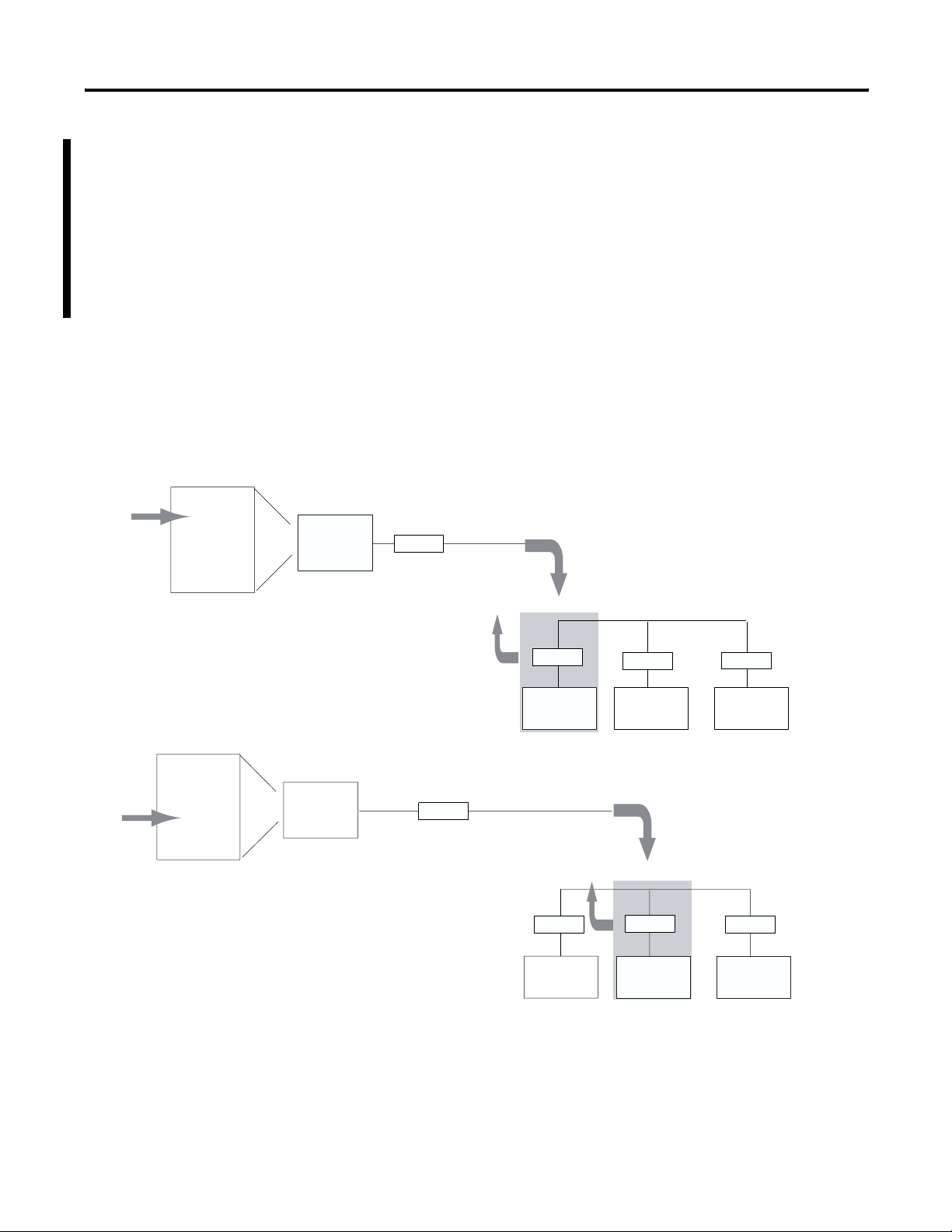
1. Master station polls a slave station for data.
2. If the slave station has data to send, then it sends a
data packet. If there is no data to send then it sends
an end of transmission packet (DLE EOT).
Standard-communication mode for an Allen-Bradley master station
uses centralized polling to gather data from slave stations. A master
station using this communication technique asks (polls) individual
slave stations if they have any information to send. All stations on the
link ‘hear’ the master station’s requests, but only the slave station to
which a request is addressed replies. PLC-5, Logix and RSLinx master
stations poll slave stations based on an ordered list (polling list)
configured by the system designer. SLC 500 and MicroLogix master
stations poll slave stations sequentially in a range of addresses
configured by the system designer.
Figure 1.1 shows how a slave
station gets polled and how it responds.
A master station polls the slave stations in the order the slave stations
appear on the list. Slave stations send either a data packet or a packet
indicating that the station has no data to send.
Figure 1.1 Slave Station Polling and Response
Master
Station
Modem
Return Data
Packet or DLE
EOT to Master
Modem
slave
station 1
Poll to slave
Modem
slave
station 2
Modem
slave
station 3
Polling List
Stn 1
Stn 2
Master
Station
Stn 3
1. Master station polls the next slave station for data.
2. If the slave station has data to send, then it sends a
data packet. If there is no data to send then it sends
an end of transmission packet (DLE EOT).
3. Master station continues to poll each slave station
in the polling list. When the end of the list is
reached, the master station then moves back to the
beginning of the list and starts the polling sequence
over again.
Publication AG-UM008C-EN-P - February 2005
Modem
Return Data
Packet or DLE
EOT to Master
Modem
slave
station 1
Modem
slave
station 2
Poll to slave
Modem
slave
station 3
41180
Page 27
Designing Communication 1-9
When the master station is configured for standard-communication
mode, you do not need to program any master-station message
instructions to communicate with slave stations. Communication with
slave stations occurs by the master station sending polling packets to
slave stations. You only need message instructions when you want the
master station to write data to or read data from a location within a
slave station’s data table.
To help you understand See
standard-communication mode Figure 1.2
how a master station requests data Figure 1.3
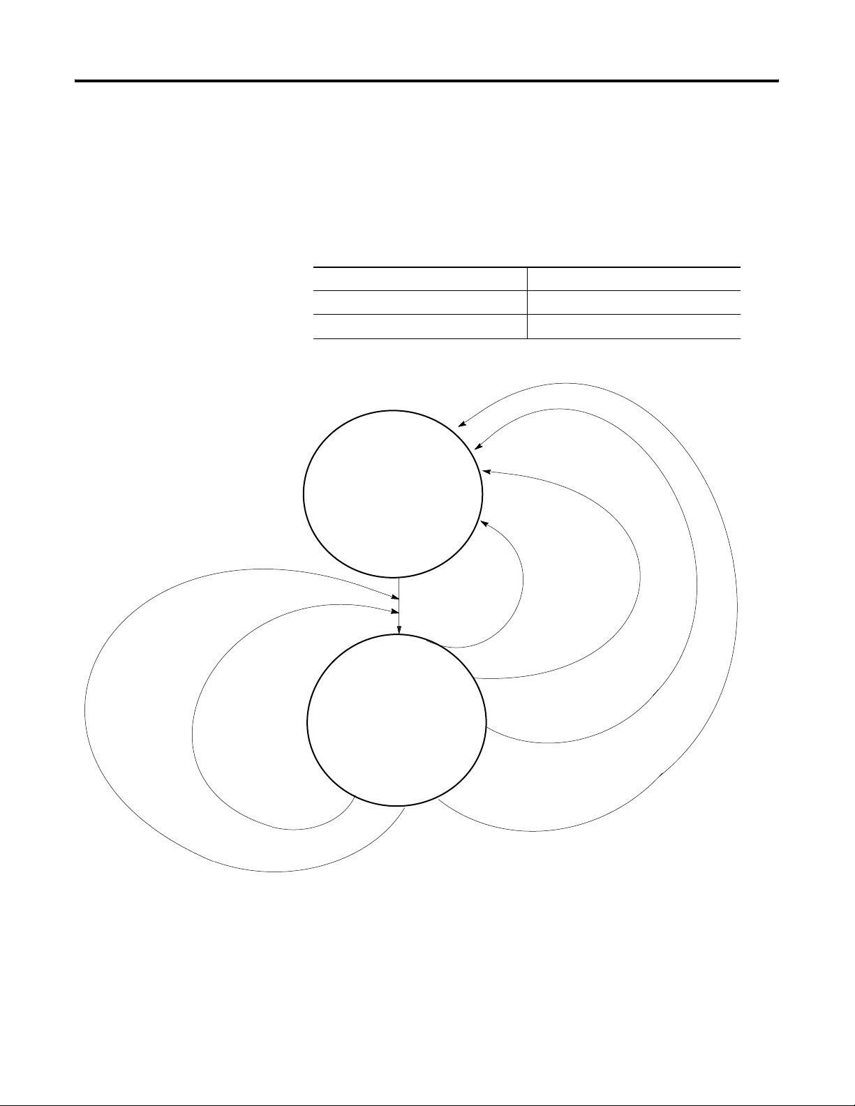
Figure 1.2 Standard Communication Mode
• Check for and send
outgoing MSG
• Select next station
to poll
timeout received and
station active and tries
< or = ‘DF1 message
retries’
MSG received and
multiple mode
forward data to or
return data from
data table
timeout received and
station inactive
• Send poll
• Start ACK timeout
• Wait for EOT or
MSG (or timeout)
timeout received and
station active and
tries > ‘DF1 message
retries’ make
station inactive
EOT received indicating no MSG to
send make station active
(if inactive)
MSG received and single
poll mode forward data
to or return data from
data table
41181
Publication AG-UM008C-EN-P - February 2005
Page 28

1-10 Designing Communication
Master data table
reply packet
received return
data
Figure 1.3 How a Master Station Requests Data
• Ladder logic
triggers MSG
• Master driver
formats command
packet
ACK timeout received and
tries > ‘DF1 message
retries’ return error
indication
• Send command
packet
• Start ACK timer
• Wait for ACK (or
timeout)
ACK timeout received
and station active and
tries < or = ‘DF1 message
retries’
reply timeout received
return error
indication
• Start reply timer
• Resume polling
• Wait for reply (or
timeout)
ACK received
To design a communication scheme using standard-communication
mode, you must do the following:
• design a polling scheme
• plan for timing issues
41182
Publication AG-UM008C-EN-P - February 2005
Page 29

Designing Communication 1-11
Designing a Polling Scheme
Each master station in a SCADA application must have a polling
scheme configured. To design a polling scheme, do the following:
• choose the type of scheme best suited for your application
• optimize your polling scheme to obtain the best efficiency
The master station you are using determines the type of polling
choices you have; however, Allen-Bradley master stations offer similar
choices, such as:
• normal and priority polling lists
• ability to poll a slave station:
– once per occurrence in the poll list (single)
– until it has no more messages to send (multiple)
Choosing Normal or Priority Polling Lists
Slave stations listed in a priority poll list are polled more frequently
than those listed in the normal poll list. Place the slave stations that
you need information from more frequently in a priority poll list.
Within each poll list, slave stations are assigned a status, which is
either active or inactive. A slave station becomes inactive when it does
not respond to a master station’s poll packet after the configured
number of retries.
If your master station is a Logix controller or PLC-5, you can use
application logic to reorder the polling lists and priority while the
application logic is executing.
Figure 1.4 and Figure 1.5 show how normal and priority lists relate to
one another.
Publication AG-UM008C-EN-P - February 2005
Page 30
1-12 Designing Communication
Figure 1.4 The master station scans slave stations in a set sequence.
1. Scans all stations in the active priority
2. Scans one station in the inactive priority
3. Scans stations in the active normal poll file
4. Scans one station in the inactive normal poll file
Active Priority
Inactive Priority
Active Normal
poll file.
poll file.
based on the normal poll group size, which you
specify during configuration. For example, if
the group size were 3, then three stations
would be polled in the normal file before the
master continues to the next step in the
sequence.
after all stations in the active normal list have
been polled.
Figure 1.5 Here is how the polling sequence applies to an application.
Poll List
STN1
STN7
Poll List
STN2
STN6
Poll List
STN3
STN4
Group size = 1
Active Priority
Poll List
Master
Station
Inactive Priority
Poll List
Active Normal
Poll List
aa
bb
cc
dd
Modem
Inactive Normal
Poll List
41183
Polling Sequence:
STN1
STN7
STN2
STN3
STN1
STN7
STN6
STN4
STN5
Inactive Normal
Beginning of new scan
Poll List
STN5
Modem
1
Modem
2
Modem
3
Modem
4
Modem
5
Modem
6
Modem
7
41184
Publication AG-UM008C-EN-P - February 2005
Page 31

Designing Communication 1-13
Choosing Single or Multiple Message Transfer
Depending on your application’s requirement, you can choose the
number of messages you want to receive from a slave station during
its turn.
If you want to receive Choose
only one message from a slave station per poll
per a station’s turn.
Choose this method only if it is critical to keep the
poll list scan time to a minimum.
single transfer
as many messages from the slave station as it has
in its queue.
multiple transfer
Planning for Timing Issues
Two types of timing categories exist.
• Protocol timers, which specify how long a master station will
wait to ‘hear’ from a slave station.
• Request to send (RTS) timers, which you can use to make sure
the modem is ready to accept data or has passed on the data
(does not apply when control line is configured for No
Handshaking).
Set and adjust these timing values as necessary for your application.
Set your RTS times based on the communication media and modem
you are using.
Design Considerations
• Define a polling list type to use (normal or priority).
• Define a station list.
• Use Figure 1.6 to help understand how the MSGs are handled
using standard communication.
Publication AG-UM008C-EN-P - February 2005
Page 32

1-14 Designing Communication
1. Polled station 1; ready to poll station 2.
2. MSG sent to station 3 (MSG was waiting in queue).
Polling List
Stn 1
Stn 2
Stn 3
Figure 1.6 Effect of MSGs on Logix, PLC-5, SLC 500, and MicroLogix Polling
Master
Station
Modem
MSG to slave
3. Master station continues polling where it left off in the polling
sequence, e.g., station 2.
Polling List
Stn 1
Stn 2
Master
Station
Stn 3
4. Master station polls station 3.
5. Station 3 replies with data.
Polling List
Stn 1
Stn 2
Master
Station
Modem
Stn 3
Modem
Modem
slave
station 1
Return Data Packet
or DLE EOT to
Master
Modem
slave
station 1
Modem
slave
station 2
Poll to slave
Modem
slave
station 2
Return Data Packet
to Master
Modem
slave
station 3
Modem
slave
station
Poll to slave
6. Master station returns to beginning of the poll list.
Publication AG-UM008C-EN-P - February 2005
Modem
slave
station 1
Modem
slave
station 2
Modem
slave
41185
station 3
Page 33

Designing Communication 1-15
Communication Scheme Design Using Message-Based Mode
Master
Station
3. Master station waits a user-defined time ‘Reply
Modem
Message Wait’ parameter before polling the
station for a reply.
In message-based communication mode, the master station sends
solicited messages (messages programmed via ladder logic) to a
specific slave station when the master requires information. In this
mode, the communication link is inactive until the master station has a
message to send to a slave station.
Figure 1.7 explains the
communication sequence that occurs.
Figure 1.7
Message-Based Communication
1. Message (via MSG instruction) sent
to a specific slave station
(eg., slave station 1).
2. Slave station receives message and
sends an acknowledgment back (ACK).
Modem
Slave
Station 1
4. Slave station forms a reply message to the
master station’s enquiry.
Modem
Slave
Station 2
5. Master station polls slave station for its reply.
6. Slave station sends its reply message.
7. Master station receives reply and sends an
acknowledgement back (ACK).
41186
Publication AG-UM008C-EN-P - February 2005
Page 34

1-16 Designing Communication
Designing Communication for DF1 Full-Duplex Protocol
Data table
reply packet received
return data
When designing communication using DF1 full-duplex protocol, you
must configure timeout values and retry counts that control the
communication between a transmitting station and a receiving station.
Consider the type of link media you are using to help you determine
the best values for the timer and counters. For example, you can
expect a message being sent over a satellite link to take longer than
one being sent over a telephone leased-line link.
Figure 1.8 shows the
communication sequence for DF1 full-duplex protocol.
Figure 1.8 Read or Write Requests via DF1 Full-Duplex
• Ladder logic
triggers MSG
• DF1 driver
formats
command
packet
NAK received and retries
NAK received and retries >
‘NAK retries’
or
ACK timeout received and
tries > ‘ENQ retries’ return
error indication
• Send command
packet
• Start ACK timer
• Wait for ACK
(or timeout)
< or = ‘NAK retries’
or
ACK timeout received and
tries < or = ‘ENQ retries’
send enquiry
reply timeout received
return error indication
Publication AG-UM008C-EN-P - February 2005
• Start reply
timer
• Wait for
reply (or
timeout)
ACK received
41187
Page 35

Designing Communication 1-17
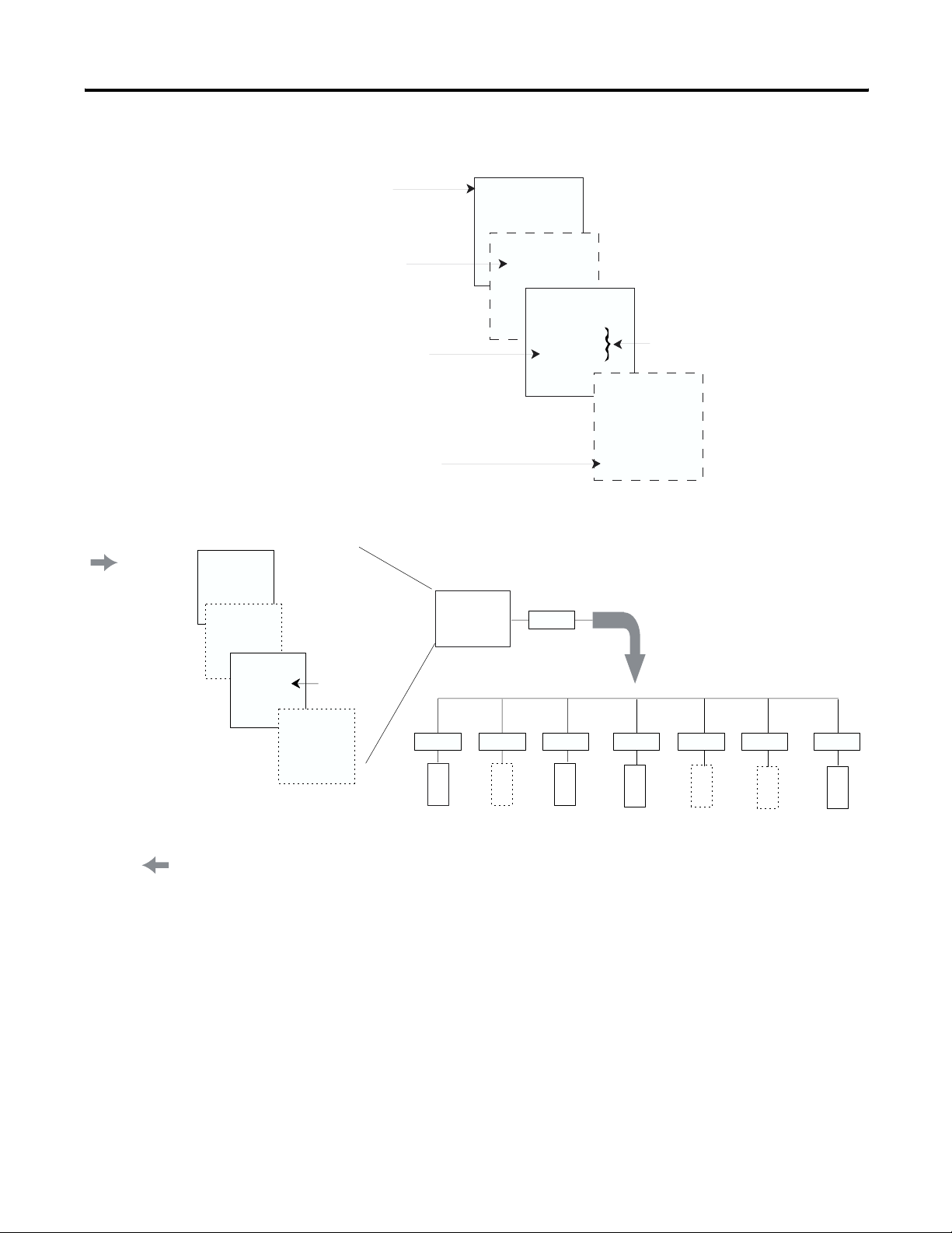
Designing Communication for DF1 Radio Modem Protocol
When designing communication using DF1 Radio Modem protocol,
you must consider the capabilities of both the controllers and radio
modems. The DF1 Radio Modem protocol can only be used with
contollers that support and are configured for this protocol.
Determining When to Use DF1 Radio Modem Protocol
If your radio modem can handle full-duplex data port buffering and
radio transmission collision avoidance, you can use peer-to-peer
message initiation capability in every node (i.e., the ladder logic in
any node can trigger a MSG instruction to any other node at any
time). For messaging between nodes that are outside of radio
transmission/reception range of each other, you may use either the
Store and Forward capability of the protocol or the repeater capability
of the radios.
If your radio modem cannot handle full-duplex data port buffering
and radio transmission collision avoidance, you can still use DF1
Radio Modem protocol in a Master/Slave configuration, with message
initiation limited to a single master node. If you still require slave
node message initiation, then you must use the DF1 Half-Duplex
protocol.
The primary advantage of using DF1 Radio Modem protocol for radio
modem networks is in the transmission efficiency. Each read/write
transaction (command and reply) requires only one transmission by
the initiator (to send the command) and one transmission by the
responder (to return the reply) as illustrated in
of transmissions is minimized, radio power is minimized, and
throughput is maximized. In contrast, DF1 Half-Duplex protocol
requires five transmissions for the DF1 Master to complete a
read/write transaction with a DF1 Slave as illustrated in
Figure 1.10 illustrates the DF1 Radio Modem protocol.
An efficiency trade-off exists in that the DF1 Radio Modem protocol
does not provide immediate feedback (ACK) to the initiator to indicate
that the responder successfully received the communications packet
without error.
The Store and Forward capability of the DF1 Radio Modem protocol
allows messages between nodes that are outside of radio
transmission/reception range of each other to be routed through
intermediary nodes that are within range. Each of the intermediary
nodes needs a Store and Forward table. The configuration needs to
indicate, based on the source and destination addresses in the
message packet, which packets to receive (store) and then
re-broadcast (forward).
capability.
Figure 1.11 illustrates the Store and Forward
Figure 1.9. The number
Figure 1.7.
Publication AG-UM008C-EN-P - February 2005
Page 36

1-18 Designing Communication
Station 2
Figure 1.9
DF1 Radio Communication
1. Message (via MSG instruction) sent to a specific
station (eg., station 1).
Modem
2. Station 1 sends its reply message.
Figure 1.10
Read or Write Requests via DF1 Radio Modem
Modem
Station 1
• Ladder logic
triggers MSG
• DF1 driver
formats
command
packet
Data table
reply packet received return data
reply timeout received
return error indication
• Send command
packet
• Start reply
timer
• Wait for reply
(or timeout)
Publication AG-UM008C-EN-P - February 2005
Page 37

Designing Communication 1-19
Figure 1.11
Applying Store and Forward in DF1 Radio Modem Protocol
What to Do Next?
Node 1
No Bits
(DST=4, SRC=1)
Make sure you:
• choose the communication method best suited for your
• make initial configuration choices for the communication
• use this chapter as a reference as you configure the devices in
(2nd rebroadcast)
REPLY 1
CMD 1
Node 2
1, 3, 4
CMD 1
(1st rebroadcast)
application.
method you have chosen.
your SCADA system.
(1st rebroadcast)
REPLY 1
Node 3
1, 2, 4
CMD 1
(2nd rebroadcast)
REPLY 1
(DST=1, SRC=4)
Node 4
No Bits
Publication AG-UM008C-EN-P - February 2005
Page 38

1-20 Designing Communication
Publication AG-UM008C-EN-P - February 2005
Page 39

Chapter
Configuring Enhanced PLC-5 Processors
2
Chapter Objectives
Overview
This chapter helps you set up an Enhanced PLC-5 processor as a
master station, as a slave station, or as a station on a point-to-point
link.
For information about See page
an overview of the tasks required to configure a PLC-5 processor 2-1
installing the processor 2-2
configuring the processor as a DF1 half-duplex master station using
standard-communication mode
configuring the processor as a DF1 half-duplex master station using
message-based communication mode
configuring the processor as a slave station 2-15
configuring the processor as a station on a point-to-point link 2-20
the types of messages you can send from a PLC-5 processor to
another processor, how to configure the MSG instruction, and some
configuration characteristics
To configure an Enhanced PLC-5 processor, perform these tasks:
2-3
2-11
2-23
1. Install the processor; connect the serial cable to channel 0.
2. Define the processor’s communication characteristics using your
PLC-5 programming software.
3. Install and configure the modem for communication with the
processor. Connect the modem to the processor’s serial channel.
1 Publication AG-UM008C-EN-P - February 2005
Page 40

2-2 Configuring Enhanced PLC-5 Processors
Figure 2.1 Configuring and Enhanced PLC-5
Modem
PLC-5
programming
software
41188
Installing the Processor
Before installing the processor, set the processor switch assemblies.
Define By setting switch assembly
DH+ and DF1 point-to-point station address S1
RS-232 as the electrical interface for the serial
S2
port
For details about installing the processor, see the Enhanced PLC-5
Programmable Controllers Quick Start, publication 1785-QS012.
For cable pinouts, see Figure 2.2 or Appendix A-2.
Figure 2.2 Enhanced PLC-5 Serial Port Pin Assignments and S2 Settings.
25-pin male 25-pin 9-pin
C. GND 1 1 NC
TXD.OUT 2 2 3
RXD.IN 3 3 2
RTS.OUT 4 4 7
CTS.IN 5 5 8
DSR.IN 6 6 6
SIG.GND 7 7 5
DCD.IN 8 8 1
DTR.OUT 20 20 4
Publication AG-UM008C-EN-P - February 2005
Page 41

Configuring Enhanced PLC-5 Processors 2-3
T
Configuring a DF1 Half-Duplex Standard Mode Master Station
Toggle pushed
toward TOP
OFF
Toggle pushed
toward BOTTOM
ON
o Specify:
RS-232C
Set Switches:
12345678910
ON ON ON OFF OFF ON ON OFF ON OFF
The DF1 Point-to-Point Station Address of the processor is the same as
the DH+ address defined by S1.
Choose standard-communication mode if you want to query slave
stations for information based upon user-configured polling lists. This
mode is used most often in point-to-multipoint configurations because
it allows polled report-by-exception (
page 1-4), slave-to-slave
messaging (page 1-5) and slave programming over the telemetry
network to be implemented. In addition, in this mode the master
station maintains an active node table which allows an HMI or
programming terminal to immediately identify which slave nodes can
currently communicate and which nodes cannot.
ATTENTION
Connect only the pins shown in figure 2.2. Do not
use a ribbon cable or one that connects to every
25-pin.
Publication AG-UM008C-EN-P - February 2005
Page 42

2-4 Configuring Enhanced PLC-5 Processors
1. Double-click on the Channel
Configuration file to bring up
the Edit Channel Properties
interface.
2. On the Channel 0 tab, choose
System (Master) for your
Communication Mode.
To configure the processor for a master station using standard
communication, place the processor into program mode and follow
the steps below using your RSLogix
™ 5 software:
3. Configure the Serial Port,
Options, and Polling
parameters according to
Table 2.1.
4.Configure Options parameters
according to Table 2.1.
5. Configure the Polling
parameters according to
Table 2.1.
6. When all parameters are set,
click OK.
7. Create station lists (page 2-8).
Publication AG-UM008C-EN-P - February 2005
Page 43

Configuring Enhanced PLC-5 Processors 2-5
Define the Communication Driver Characteristics
Use Table 2.1 to help you understand the communication parameters
you need to specify on the Channel Configuration screen for
standard-communication mode.
Use Worksheet 2.1 (page D-5) for an example configuration and to
record your station’s configuration.
Table 2.1 Communication Parameters for a PLC-5 Master Station Using
Standard-Communication Mode
RSLogix 5 Tab Parameter Selections
Channel 0 Diagnostic File Select an unused integer file to store channel status information. You must define a diagnostic
file in order to be able to view channel 0 status. See
description of what is in this file.
See Table 2.2 on page 2-8 for a
Remote Mode
Change
Mode Attention
Character
System Mode
Character
User Mode
Character
Serial Port Baud Rate Select a communication rate that all devices in your system support. Configure all devices in
Bits Per Character Match the number of bits per character to the devices with which you are communicating.
Stop Bits Match the number of stop bits to the devices with which you are communicating.
Control Line This parameter defines the mode in which the master driver operates. Choose a method
Check enable remote mode change if you want to switch the configuration of the channel
during runtime. Leave the parameter set at the default (unchecked) if you are not using this
feature.
Select a character that will signal a remote mode change. Leave the parameter set at the
default if you are not using remote mode change.
Select a character that will signal the channel to switch into system mode. Leave the
parameter set at the default if you are not using remote mode change.
Select a character that will signal the channel to switch into user mode. Leave the parameter
set at the default if you are not using remote mode change.
the system for the same communication rate.
appropriate for your system’s configuration:
• If you are not using a modem, choose NO HANDSHAKING.
• If the master modem is full duplex and the slave modem is full-duplex, choose
FULL-DUPLEX MODEM.
• If all the modems in the system are half-duplex, choose HALF-DUPLEX MODEM
WITHOUT CONTINUOUS CARRIER.
Serial Port Error Detect With this selection, you choose how the processor checks the accuracy of each DF1 packet
transmission.
BCC: This algorithm provides a medium level of data security. It cannot detect:
• transposition of bytes during transmission of a packet
• the insertion or deletion of data values of zero within a packet
CRC: This algorithm provides a higher level of data security.
Select an error detection method that all devices in your system support.
When possible, choose CRC.
Publication AG-UM008C-EN-P - February 2005
Page 44

2-6 Configuring Enhanced PLC-5 Processors
RSLogix 5 Tab Parameter Selections
Options Station Address Define the octal address of the processor on the DF1 half-duplex link. Each station on a link
must have a unique address. Choose an address between 0 and 376
.
8
Station address 3778 is the broadcast address, which you cannot select as a station’s
individual address.
DF1 Retries Defines the number of times a master station retries either a message before the master
station declares the message undeliverable, or poll packet to an active station before the
master station declares that station to now be inactive.
RTS Send Delay RTS send delay is the amount of time, in 20 millisecond increments, that elapses between the
assertion of the RTS signal and the beginning of the message transmission. This time allows
the modem to prepare to transmit the message.
The Clear to Send (CTS) signal must be high for transmission to occur.
RTS Off Delay RTS off delay is the amount of time, in 20 millisecond increments, that elapses between the
end of the message transmission and the de-assertion of the RTS signal. This time delay is a
buffer to make sure that the modem has transmitted the message but should normally be left
at zero.
ACK Timeout Define the amount of time, in 20 millisecond increments, that you want the processor to wait
for an acknowledgment from a slave station to its transmitted message before the processor
retries the message or the message errors out.
Reply Message
Wait
Define the amount of time, in 20 millisecond increments, that the master station will wait
after receiving an ACK (to a master-initiated message) before polling the slave station for a
reply.
Choose a time that is, at minimum, equal to the longest time that a slave station needs to
format a reply packet. This is typically the maximum scan time of the slave station.
Note: This field is only valid if the polling mode field is configured to be MESSAGE BASED.
MSG Application
Timeout
Define the number of 30 second increments within which the reply message must be received
before the error bit is set on the message. The timer starts when the ACK is received.
Polling Polling Mode If you want to receive:
• only one message from a slave station per its turn, choose STANDARD (SINGLE
MESSAGE TRANSFER PER NODE SCAN).
Choose this method only if it is critical to keep the poll list scan time to a minimum.
• as many messages from a slave station as it has, choose STANDARD (MULTIPLE
MESSAGE TRANSFER PER NODE SCAN).
Master Message
Transmit
If you want the master station to:
• send all of the master station-initiated MSG instructions to the slave stations before
polling the next slave station in the poll list, choose Between Station Polls.
This method makes certain that master station-initiated messages are sent in a timely
and regular manner (after every slave station poll).
• only send master station-initiated MSG instructions when the master’s station number
appears in the polling sequence, choose In Poll Sequence.
With this method, sending master station-initiated messages are dependent upon
where and how often the master station appears in the poll list. To achieve the same
goal as the Between Station Polls method, the master-station’s address would have to
appear after every slave-station’s address.
Publication AG-UM008C-EN-P - February 2005
Page 45

RSLogix 5 Tab Parameter Selections
Configuring Enhanced PLC-5 Processors 2-7
Polling Normal Poll Node
File
Normal Poll Group
Size
Priority Poll Node
File
Active Station File Enter an unused binary file that will store the status of all the stations in your network
1. To display Channel Status,
double-click on Channel
Status, which is located
within Channel Configuration.
Enter an unused integer file that will store the addresses of the slave stations you want in the
normal poll list.
Enter the quantity of active stations located in the normal poll list that you want polled during
a scan through the normal poll list before returning to the priority poll list.
Enter an unused integer file that will store the addresses of the slave stations you want in the
priority poll list.
configuration. The file stores one station address per bit.
0 = inactive; 1 = active.
Displaying System (Master) Channel Status
2. To access the various channels
from the Channel Status
screen, click on the tabs.
Descriptions of the status
screen fields can be found in
Table 2.2.
Publication AG-UM008C-EN-P - February 2005
Page 46

2-8 Configuring Enhanced PLC-5 Processors
Table 2.2 Descriptions of System Mode DF1 Master Channel Status Fields
Status Field Location Description
Clear Clear counters for all channels by clicking on Clear button.
DCD Recover word 11 Displays the number of times the processor detects the DCD handshaking line has
gone low to high.
Lost Modem word 12 Displays the number of times that the modem lost bit (S:17/5) has gone low to high.
Messages Sent word 1 Displays the number of messages sent by the processor (including message retry).
Messages Received word 2 Displays the number of messages the processor received with no error.
Undeliverable Messages word 3 Displays the number of messages that were sent by the processor but not received
by the destination device.
Messages Retry word 4 Displays the number of messages resent.
Duplicate Messages Received word 9 Displays the number of times the processor received a message packet identical to
the previous message packet.
EOT Received on First Poll word 8 Displays the number of times the Master received an EOT in response to the first
poll of a station.
Bad Packet / No ACK word 7 Displays the number of incorrect data packets that the processor has received.
Last Normal Poll List Scan (100 ms) word 5 The time it took to complete the previous scan of the normal station poll list.
Max Normal Poll List Scan (100 ms) word 6 The maximum time taken to complete a scan of the normal station poll list.
Last Priority Poll List Scan (100 ms) word 10 The time it took to complete the previous scan of the priority station poll list.
Max Priority Poll List Scan (100 ms) word 13 The maximum time taken to complete a scan of the priority station poll list.
DTR (Data Terminal Read) word 0; bit 4 Displays the status of the DTR handshaking line (asserted by the processor).
DCD (Data Carrier Detect) word 0; bit 3 Displays the status of the DCD handshaking line (received by the processor).
DSR (Data Set Ready) word 0; bit 2 Displays the status of the DSR handshaking line (received by the processor).
RTS (Request to Send) word 0; bit 1 Displays the status of the RTS handshaking line (asserted by the processor).
CTS (Clear to Send) word 0; bit 0 Displays the status of the CTS handshaking line (received by the processor).
Create Station Lists
After defining your polling files and group size, create station lists by
entering the station address of each slave station into either the
normal poll file or priority poll file of the PLC-5 data table. Place each
station address in an individual word in a poll file (normal and
priority) starting at word 2.
Publication AG-UM008C-EN-P - February 2005
Page 47

Configuring Enhanced PLC-5 Processors 2-9
The normal and priority poll file layout is as follows:
This word in a poll file Contains this information
word 0 total number of stations to be polled (for a list)
word 1 the address location (poll offset) of the station currently
being polled (as long as all configured stations are active)
For example: a value of 1 means the station address
stored in word 2 is being polled, 2 means the address
stored in word 3 is being polled, etc.
This word is automatically updated by the master station
as a new slave station is polled.
word 2 through word xx the slave station address in the order that the stations
should be polled
Store one station address in each word.
To place a station address in a poll file:
1. Access the PLC-5 data table.
2. Specify the address of the integer file that is either the normal
poll file or priority poll file (e.g., If the normal poll file is N11,
then you specify N11:0).
3. Enter the station addresses of the slave stations you want in the
poll list starting at word 2. Put them in the order you want them
polled.
IMPORTANT
PLC-5 station addresses are octal addresses.
The poll files are integer files that default to a
decimal radix. To properly enter PLC-5 station
addresses in a poll file, you must either:
• change the radix of the file to octal
• convert the PLC-5 octal station addresses to
decimal
Publication AG-UM008C-EN-P - February 2005
Page 48

2-10 Configuring Enhanced PLC-5 Processors
total number
of stations
pointer showing the station
address being polled
Figure 2.3 is an example of a station list containing three stations:
octal addresses 10, 3, and 12. Station 12 is being polled.
Figure 2.3 Example Station List
address of first
station in list
address of second
station in list
address of third
station in list
Monitor Active Stations
To see what stations are active, view the active station file. Each bit in
the file represents a station on the link. The stations are numbered in
order as a continuous bit-stream file starting with the first bit in the
first word (
Figure 2.4 Example Active Station File
Address 15 Data 0
B11:0 1111 1111 1111 1111 Remote station 0
B11:1 1111 1111 1111 1111 Remote station 16
B11:2 1111 1111 1111 1111
Figure 2.4).
10
For PLC-5 processors:
Starting with these PLC-5
firmware revisions
Series E/Revision B
Series D/Revision C
Series C/Revision L
Series B/Revision M
Series A/Revision M
For all prior firmware revisions At power-up or after reconfiguration, the master
This is what you will see
At power-up or after reconfiguration, the master
station assumes that all slave stations are
inactive (bit=0).
station assumes that all slave stations are active
(bit=1) and the station displays inactive only after
it fails to respond to a poll packet.
Publication AG-UM008C-EN-P - February 2005
Page 49

Configuring Enhanced PLC-5 Processors 2-11
Configuring a DF1 Half-Duplex Message-based Mode Master Station
Choose message-based communication mode if you want to use MSG
instructions in user programming to communicate with one station at
a time. If your application uses satellite transmission or public
switched telephone network transmission, consider choosing
message-based. Communication to a slave station can be initiated on
an as-needed basis.
Also choose message-based mode when a redundant PLC-5 system is
being used as a master station. Connect both PLC-5 processor serial
ports to the master station modem through an RS-232 modem splitter
and precondition all MSG instructions with the Primary Processor
status bit.
With message-based mode, you do not have an active station file that
you can use to monitor station status. Also, you cannot implement
slave-to-slave messaging or slave programming over the telemetry
network.
To configure the processor for a master station using message-based
communication, place the processor in program mode and follow the
steps below using RSLogix 5:
1. Double-click on the Channel
Configuration file to bring up
the Edit Channel Properties
interface.
2. On the Channel 0 tab, choose
System (Master) for your
Communication Mode.
3. Configure the Serial Port,
Options, and Polling
parameters according to
Table 2.3.
Publication AG-UM008C-EN-P - February 2005
Page 50

2-12 Configuring Enhanced PLC-5 Processors
4.Configure Options parameters
according to Table 2.3.
5. Configure the Polling
parameters according to
Table 2.3.
6. When all parameters are set,
click OK.
Use Table 2.3 to help you understand the communication parameters
you need to specify on the Edit Channel Properties screen.
Use Worksheet 2.2 (page D-6) for an example configuration and to
record your station’s configuration.
Table 2.3 Communication Parameters for a PLC-5 Master Station Using
Message-Based Communication Mode
RSLogix 5 Tab Parameter Selections
Channel 0 Diagnostic File Select an unused integer file to store channel status information. You must define a
diagnostic file in order to be able to view channel 0 status.
description of what’s in this file.
Remote Mode Change Check enable remote mode change if you want to switch the configuration of the channel
during runtime. Leave the parameter set at the default (unchecked) if you are not using
this feature.
Mode Attention
Character
Select a character that will signal a remote mode change. Leave the parameter set at the
default if you are not using remote mode change.
System Mode Character Select a character that will signal the channel to switch into system mode. Leave the
parameter set at the default if you are not using remote mode change.
User Mode Character Select a character that will signal the channel to switch into user mode. Leave the
parameter set at the default if you are not using remote mode change.
Serial Port Baud Rate Select a communication rate that all devices in your system support. Configure all
devices in the system for the same communication rate.
Bits Per Character Match the numbers of bits per character to the devices with which you are
communicating.
Stop Bits Match the number of stop bits to the devices with which you are communicating.
See Table 2.2 on page 2-8 for
Publication AG-UM008C-EN-P - February 2005
Page 51

Configuring Enhanced PLC-5 Processors 2-13
RSLogix 5 Tab Parameter Selections
Serial Port Control Line This parameter defines the mode in which the master driver operates. Choose a method
appropriate for your system’s configuration:
• If you are not using a modem, choose NO HANDSHAKING.
• If the master modem is full duplex and the slave modem is full-duplex, choose
FULL-DUPLEX MODEM.
• If all the modems in the system are half-duplex, choose HALF-DUPLEX MODEM
WITHOUT CONTINUOUS CARRIER.
Parity Parity provides additional message packet error detection. To implement even parity
checking, choose Even. To implement no parity checking, choose None.
Error Detect With this selection, you choose how the processor checks the accuracy of each DF1
packet transmission.
BCC: This algorithm provides a medium level of data security. It cannot detect:
• transposition of bytes during transmission of a packet
• the insertion or deletion of data values of zero within a packet
CRC: This algorithm provides a higher level of data security.
Select an error detection method that all devices in your system support.
When possible, choose CRC.
Options Station Address Define the octal address of the processor on the DF1 half-duplex link. Each station on a
link must have a unique address. Choose an address between 0 and 376
.
8
Station address 3778 is the broadcast address, which you cannot select as a station’s
individual address.
DF1 Retries Define the number of times a master station retries either a message before the master
station declares the message undeliverable, or a poll packet to an active station before
the master station declares the station to be inactive.
RTS Send Delay RTS send delay is the amount of time, in 20 millisecond increments, that elapses
between the assertion of the RTS signal and the beginning of the message transmission.
This time allows the modem to prepare to transmit the message. The Clear to Send (CTS)
signal must be high for transmission to occur.
RTS Off Delay RTS off delay is the amount of time, in 20 millisecond increments, that elapses between
the end of the message transmission and the de-assertion of the RTS signal. This time
delay is a buffer to ensure that the modem has transmitted the message but should
normally be left at zero.
ACK Timeout Define the amount of time, in 20 millisecond increments, that you want the processor to
wait for an acknowledgment from a slave station to its transmitted message before
retrying. This timeout value is also used for the poll response timeout.
Reply Message Wait Define the amount of time, in 20 millisecond increments, that the master station will wait
after receiving an ACK (to a master-initiated message) before polling the slave station for
a reply.
Choose a time that is, at minimum, equal to the longest time that a slave station needs to
format a reply packet. This is typically the maximum scan time of the slave station.
MSG Application
Timeout
The application timeout of the message is the number of 30 second increments within
which the reply message must be received before the error bit is set on the message. The
timer starts when the ACK is received.
Publication AG-UM008C-EN-P - February 2005
Page 52

2-14 Configuring Enhanced PLC-5 Processors
RSLogix 5 Tab Parameter Selections
Polling Polling Mode If you want to:
• accept unsolicited messages from slave stations, choose MESSAGE BASED
(ALLOW SLAVE TO INITIATE MESSAGES).
Slave station-initiated messages are acknowledged and processed after all
master station-initiated (solicited) messages.
Note: Slave stations can only send messages when they are polled. If the
message-based master station never sends a slave station a message, the master
station will never send the slave station a poll. Therefore, to regularly obtain a
slave station-initiated message from a slave station, you should choose to use
standard communications mode instead.
• ignore unsolicited messages from slave stations, choose MESSAGE BASED
(DO NOT ALLOW SLAVES TO INITIATE MESSAGES).
Slave station-initiated messages are acknowledged and discarded. The master
station acknowledges the slave station-initiated message so that the slave
station removes the message from its transmit queue, which allows the next
packet slated for transmission into the transmit queue.
Master Message
Transmit
If you want the master station to:
• send all of the master station initiated MSG instructions to the remote stations
before polling the next remote station in the poll list, choose Between Station
Polls.
This method makes certain that master station initiated messages are sent in a
timely and regular manner (after every remote station poll).
• send only master station initiated MSG instructions when the master’s station
number appears in the polling sequence, choose In Poll Sequence.
With this method, sending master station initiated messages are dependent on
where and how often the master station appears in the poll list. To achieve the
same goal as Between Station Polls method, the master station’s address would
need to appear after every remote station’s address.
Normal Poll Node File Enter an unused integer file that will store addresses of the remote stations you want in
the normal poll list.
Active Station File Enter an unused binary file that will store the status of all the stations in your network
configuration. The file stores one address per bit. 0=inactive, 1=active.
Priority Poll Node File Enter an unused integer file that will store the addresses of the remote stations you want
in the priority poll list.
Normal Poll Group Size Enter the quantity of active stations located in the normal poll list that you want polled
during a scan through the normal poll list before returning to the priority poll list.
Publication AG-UM008C-EN-P - February 2005
Page 53

Configuring Enhanced PLC-5 Processors 2-15
Configuring the Processor as a Slave Station
1. Double-click on the Channel
Configuration file to bring up
the Edit Channel Properties
interface.
2. On the Channel 0 tab, choose
System (Slave) for your
Communication Mode.
To configure the processor as a slave station, place the processor in
program mode and follow the steps below using your programming
software:
3. Configure the Serial Port
parameters according to
Table 2.4.
4.Configure the Options
parameters according to
Table 2.4.
5. When all parameters are set,
click OK.
Use Table 2.4. to help you understand the communication parameters
you need to specify on the Channel Configuration screen.
Use Worksheet 2.3 (page D-7) for an example configuration and to
record your station’s configuration.
Publication AG-UM008C-EN-P - February 2005
Page 54

2-16 Configuring Enhanced PLC-5 Processors
Table 2.4 Communication Parameters for a PLC-5 Slave Station.
RSLogix 5 Tab Parameter Selections
Channel 0 Diagnostic File Select an unused integer file to store channel status information. You must define a
diagnostic file in order to be able to view channel 0 status.
See Table 2.5 on
page 2-18 for a description of what this file contains.
Remote Mode Change
Enable
Check enable remote mode change if you want to switch the configuration of the
channel during runtime. Leave the parameter set at the default (unchecked) if you
are not using this feature.
Mode Attention Character Select a character that will signal a remote mode change. Leave the parameter set
at the default if you are not using remote mode change.
System Mode Character Select a character that will signal the channel to switch into system mode. Leave
the parameter set at the default (unchecked) if you are not using remote mode
change.
User Mode Character Select a character that will signal the channel to switch into user mode. Leave the
parameter set at the default if you are not using remote mode change.
Serial Port Baud Rate Select a communication rate that all devices in your system support. Configure all
devices in the system for the same communication rate.
Bits Per Character Match the number of bits per character to the devices with which you are
communicating.
Stop Bits Match the number of stop bits to the devices with which you are communicating.
Control Line This parameter defines the mode in which the slave station driver operates. Choose
a method appropriate for your system’s configuration:
• If you are not using a modem, choose NO HANDSHAKING.
• If the master modem is full duplex and transmits a constant carrier and the
slave modem is half-duplex, choose HALF-DUPLEX MODEM WITH
CONTINUOUS CARRIER.
• If all the modems in the system are half-duplex, choose HALF-DUPLEX
MODEM WITHOUT CONTINUOUS CARRIER.
Parity Parity provides additional message packet error detection. To implement even parity
checking, choose Even. To implement no parity checking, choose None.
Serial Port Error Detect With this selection, you choose how the processor checks the accuracy of each DF1
packet transmission.
BCC: This algorithm provides a medium level of data security. It cannot detect:
• transposition of bytes during transmission of a packet
• the insertion or deletion of data values of zero within a packet
CRC: This algorithm provides a higher level of data security.
Select an error detection method that all devices in your system support.
When possible, choose CRC.
Publication AG-UM008C-EN-P - February 2005
Page 55

Configuring Enhanced PLC-5 Processors 2-17
RSLogix 5 Tab Parameter Selections
Options Station Address Define the octal address of the processor on the DF1 half-duplex link. Each station
on a link must have a unique address. Choose an address between 0 and 376
.
8
Station address 3778 is the broadcast address, which you cannot select as a
station’s individual address.
DF1 Retries The number of times a slave station retries a message before the slave station
declares the message undeliverable.
RTS Send Delay RTS send delay is the amount of time, in 20 millisecond increments, that elapses
between the assertion of the RTS signal and the beginning of the message
transmission. This time allows the modem to prepare to transmit the message.
The CTS (Clear-to-Send) signal must be high for transmission to occur.
RTS Off Delay RTS off delay is the amount of time, in 20 millisecond increments, that elapses
between the end of the message transmission and the de-assertion of the RTS
signal. This time delay is a buffer to make sure that the modem has transmitted the
message but should normally be left at zero.
ACK Timeout Define the amount of time, in 20 millisecond increments, that you want the
processor to wait for an acknowledgment from the master station to its transmitted
message.
Detect Duplicate Messages Duplicate packet detection lets the PLC-5 processor detect if it has received a
message that is a duplicate of its most recent message from the master station. If
you choose detect duplicate messages, the processor will acknowledge (ACK) the
message but will not act on it since it has already performed the message’s task
when it received the command from the first message.
If you want to detect duplicate packets and discard them, check this parameter. If
you want to accept duplicate packets and execute them, leave this parameter
unchecked.
MSG Application Timeout Define the number of 30 second increments within which the reply message must be
received before the error bit is set on the message. The timer starts when the ACK is
received.
Publication AG-UM008C-EN-P - February 2005
Page 56

2-18 Configuring Enhanced PLC-5 Processors
1. To display Channel Status,
double click on Channel
Status, which is located
within Channel Configuration.
2. To access the various channels
from the Channel Status
Screen, click on the tabs.
Descriptions of the status
screen fields can be found in
Table 2.5.
Displaying Slave System Channel Status
Table 2.5 Descriptions of System Mode DF1 Slave Channel Status Fields
Status Field Diagnostic File Location Definition
DCD Recover word 11 The number of times the processor detects the DCD handshaking line
has gone low to high
Messages Sent word 1 The total number of DF1 messages sent by the processor (including
message retries)
Messages Received word 2 The number of messages received with no errors
Polling Received word 6 The number of master poll packets received by the processor
Received NAK word 5 The number of NAKs received by the processor
Lack of Memory/No ACK
Sent
word 8 The number of times the processor could not receive a message
because it did not have available memory
Lost Modem word 12 The number of times the lost modem bit has gone low to high
Messages Retry word 4 The number of message retries sent by the processor
Publication AG-UM008C-EN-P - February 2005
Page 57

Configuring Enhanced PLC-5 Processors 2-19
Status Field Diagnostic File Location Definition
Undelivered Messages word 3 The number of messages that were sent by the processor but not
acknowledged by the destination device
Duplicate Messages
Received
word 9 The number of times the processor received a message packet identical
to the previous message packet
Bad Packet/No ACK word 7 The number of incorrect data packets received by the processor for
which a no ACK was returned
DTR (Data Terminal Ready) word 0;bit 4 The status of the DTR handshaking line (asserted by the processor)
DSR (Data Set Ready) word 0;bit 2 The status of the DSR handshaking line (received by the processor)
RTS (Request to Send) word 0;bit 1 The status of the RTS handshaking line (asserted by the processor)
CTS (Clear to Send) word 0;bit 0 The status of the CTS handshaking line (received by the processor)
DCD (Carrier Detect) word 0;bit 3 The status of the DCD handshaking line (received by the processor)
Publication AG-UM008C-EN-P - February 2005
Page 58

2-20 Configuring Enhanced PLC-5 Processors
Configuring the Processor as a Station on a Point-to-Point Link
1. Double-click on the Channel
Configuration file to bring up
the Edit Channel Properties
interface.
2. On the Channel 0 tab, choose
System (Point-to-Point) for
your Communication Mode.
To configure the processor as a station on a point-to-point link, place
the processor in program mode and follow the steps below using your
programming software:
3. Configure the Serial Port
parameters according to
Table 2.6.
4.Configure the Options
parameters according to
Table 2.6.
5. When all parameters are set,
click OK.
Use Table 2.6. to help you understand the screen parameters you
need to specify on the Channel Configuration screen.
Use Worksheet 2.4 (page D-8) for an example configuration and to
record your station’s configuration.
Publication AG-UM008C-EN-P - February 2005
Page 59

Configuring Enhanced PLC-5 Processors 2-21
Table 2.6 Configuring the PLC-5 Processor as a Device on a Point-to-Point Link
RSLogix 5 Tab Parameter Selections
Channel 0 Diagnostic File Select an unused integer file that you want to use to store channel status information. You
must define a diagnostic file in order to be able to view channel 0 status.
See Table 2.7 on
page 2-22 for a description of what this file contains.
Remote Mode Change Enable remote mode change if you want to switch the configuration of the channel during
runtime. Leave the parameter set at the default if you are not using remote mode change.
Mode Attention
Character
Select a character that will signal a remote mode change. Leave the parameter set at the
default if you are not using remote mode change.
System Mode Character Select a character that will signal the channel to switch into system mode. Leave the
parameter set at the default if you are not using remote mode change.
User Mode Character Select a character that will signal the channel to switch into user mode. Leave the
parameter set at the default if you are not using remote mode change.
Serial Port Baud Rate Select a communication rate that all devices in your system support. Configure all devices
in the system for the same communication rate.
Bits Per Character Match the number of bits per character to the device with which you are communicating.
Stop Bits Match the number of stop bits to the device with which you are communicating.
Control Line This parameter defines the mode in which the driver operates. Choose a method
appropriate for your system’s configuration:
• If you are not using a modem, choose NO HANDSHAKING.
• If you are using a full-duplex modem, choose FULL-DUPLEX.
Parity Parity provides additional message packet error detection. To implement even parity
checking, choose Even. To implement no parity checking, choose None.
Options NAK Receive Define the number of NAKs the processor can receive in response to a transmitted message
before the station declares the message undeliverable.
DF1 ENQs Define the number of enquiries (ENQs) that you want the processor to send after an ACK
timeout occurs before the station declares the message undeliverable.
ACK Timeout Define the amount of time, in 20 millisecond increments, you want the processor to wait for
an acknowledgment from a station to its transmitted message.
Options Detect Duplicate
Messages
Duplicate Packet Detection lets the PLC-5 processor detect if it has received a message that
is a duplicate of its most recent message from another station. If you choose detect
duplicate messages, the processor will acknowledge (ACK) the message but will not act on
it since it has already performed the message’s task when it received the command from
the first message.
If you want to detect duplicate packets and discard them, check this parameter. If you want
to accept duplicate packets, and execute them, leave this parameter unchecked.
MSG Application
Timeout
Define the number of 30 second increments within which the reply message must be
received before the error bit is set on the message. The timer starts when the ladder
program first initiates the message and is restarted if/when the ACK is received.
Error Detect With this selection you choose how the processor checks the accuracy of each DF1 packet
transmission.
BCC: This algorithm provides a medium level of data security. It cannot detect:
• transposition of bytes during transmission of a packet
• the insertion or deletion of data values of zero within a packet
CRC: This algorithm provides a higher level of data security.
Select an error detection method that all devices in your system support.
When possible, choose CRC.
Important: The station address in the point-to-point driver is determined by the DH+ address defined by switch assembly S1.
Publication AG-UM008C-EN-P - February 2005
Page 60

2-22 Configuring Enhanced PLC-5 Processors
1. To display Channel Status,
double-click on Channel
Status, which is located
within Channel Configuration.
2. To access the various channels
from the Channel Status
screen, click on the tabs.
Descriptions of the status
screen fields can be found in
Table 2.7.
Displaying Point-to-Point System Channel Status
Table 2.7 Descriptions of System (Point-to-Point) Channel Status Fields
Status Field Diagnostic File Location Definition
DCD Recover word 11 The number of times the processor detects the DCD handshaking line has
gone low to high
Messages Sent word 1 The total number of DF1 messages sent by the processor (including
message retries)
Messages Received word 2 The number of messages received with no errors
Inquiry Received word 6 The number of master poll packets received by the processor
Received NAK word 5 The number of NAKs received by the processor
Lack of Memory/Sent NAK word 8 The number of times the processor could not receive a message because
it did not have available memory
Lost Modem word 12 The number of times the lost modem bit has gone low to high
Undelivered Messages word 3 The number of messages that were sent by the processor but not
acknowledged by the destination device
Duplicate Messages
Received
Publication AG-UM008C-EN-P - February 2005
word 9 The number of times the processor received a message packet identical
to the previous message packet
Page 61

Configuring Enhanced PLC-5 Processors 2-23
Status Field Diagnostic File Location Definition
Inquiry Sent word 4 The number of ENQs sent by the processor
Bad Packet/No ACK word 7 The number of incorrect data packets received by the processor for which
a NAK was returned
DTR (Data Terminal Ready) word 0;bit 4 The status of the DTR handshaking line (asserted by the processor)
DSR (Data Set Ready) word 0;bit 2 The status of the DSR handshaking line (received by the processor)
RTS (Request to Send) word 0;bit 1 The status of the RTS handshaking line (asserted by the processor)
CTS (Clear to Send) word 0;bit 0 The status of the CTS handshaking line (received by the processor)
DCD (Carrier Detect) word 0;bit 3 The status of the DCD handshaking line (received by the processor)
Messaging
Messaging can occur between:
• a master station and a slave station
• a slave station and its master station
(See Polled Report-by-Exception)
• slave stations or between two processors connected via a
point-to-point link
Master Station to Slave Station
A PLC-5 master station communicates with the slave stations that are
connected to it via modems in a point-to-multipoint configuration. A
master station sends a slave station messages to receive status or issue
commands. For sample messaging ladder logic, see page
E-8.
Polled Report-by-Exception
Slave stations can gather information from the I/O points they are
responsible for and can send any anomalous readings to the master
station. To do this, write ladder logic in the slave station to monitor
certain conditions and send the data in a MSG instruction to the
master station.
block that a PLC-5 processor in a slave station can send to a PLC-5
master station. For sample messaging ladder logic when using a PLC-5
as a slave, see page
Figure 2.6 is an example MSG instruction and control
E-12.
Publication AG-UM008C-EN-P - February 2005
Page 62

2-24 Configuring Enhanced PLC-5 Processors
Processor-to-Processor
A processor-to-processor message can be two types:
• In a point-to-multipoint configuration, the messaging would be
between slave stations; the master station automatically routes
the message.
Master
Station
MSG from Slave
Station 1 to Slave
Station 2
Modem
Modem
Slave
Station 1
Master Station
routes MSG to
Slave Station 2
Modem
Slave
Station 2
• In a point-to-point configuration, the messaging would be
between the two connected peer devices.
MSG
Modem
Station 1
Modem
Station 2
The configuration of the network (point-to-multipoint vs.
point-to-point) and the configuration of the station (master, slave, or
peer) does not affect how you configure a MSG instruction. That is, a
MSG instruction being sent between two PLC-5 slave stations is
configured the same as a MSG instruction between two PLC-5
processors connected point-to-point, which is configured the same as
a MSG instruction between a PLC-5 master station and a PLC-5 slave
station. See
Figure 2.5 through Figure 2.8 for example MSG control
blocks.
Publication AG-UM008C-EN-P - February 2005
Page 63

Configuring Enhanced PLC-5 Processors 2-25
Considerations When Configuring MSG Control Blocks
Keep these considerations in mind when configuring messages
between a PLC-5 and SLC 500 or MicroLogix processor.
The following table lists which PLC-5 processors (series and revision)
you can use with the MSG instruction to transfer data from/to a PLC-5
processor to/from any SLC 500 processor or MicroLogix 1000 in SLC
native mode.
Processor
Series/Revision
Series A / revision M PLC-5/40, -5/40L, -5,60, -5/60L
Series A / revision J PLC-5/30
Series A / revision H PLC-5/11, -5/20
Series B / revision J PLC-5/40, -5/40L, -5/60, -5/60L
Series C / revision G PLC-5/11, -5/20, -5/20E, -5/30, -5/40, -5/40L, -5/V40,
Series D / all PLC-5/11, -5/20, -5/20E, -5/30, -5/40, -5/40L, -5/V40,
Series E / all PLC-5/11, -5/20, -5/20E, -5/30, -5/40, -5/40L, -5/V40,
Processors
-5/V40L, -5/40E, -5/60, -5/60L, -5/80, -5/80E, -5/V80,
-5/20C, -5/40C, -5/80C
-5/V40L, -5/40E, -5/60, -5/60L, -5/80, -5/80E, -5/V80,
-5/20C, -5/40C, -5/80C
-5/V40L, -5/40E, -5/60, -5/60L, -5/80, -5/80E, -5/V80,
-5/20C, -5/40C, -5/80C
• Since all SLC 5/05, 5/04 and 5/03 processors with Operating
System 301 or higher can respond to (and initiate) PLC-5 native
mode message commands, all PLC-5 processors can transfer data
between their data tables and the data table of these particular
SLC processors (except for the I/O image table) as if they were
messaging with another PLC-5 processor.
• In a single instruction, the maximum amount of words you can
read from or write to through channel 0 is as follows:
– SLC 500, 5/01, 5/02, and MicroLogix 1000 processor, 41 words
– SLC 5/03, 5/04, 5/05, MicroLogix 1100/1200/1500 processor,
103 words
When configuring messages between a PLC-5 and Logix processor,
use the PLC-5 typed read and write commands and enclose the name
of the Logix tag in double quotes. This is called logical ASCII
addressing.
Publication AG-UM008C-EN-P - February 2005
Page 64

2-26 Configuring Enhanced PLC-5 Processors
Example MSG Control Blocks
Application See Page
PLC-5 read message to another PLC-5 processor Figure 2.5 2-26
PLC-5 write message to another PLC-5 processor Figure 2.6 2-27
Ladder Rung
Control Block
PLC-5 read message to an SLC 500 or MicroLogix 1000
Figure 2.7 2-28
processor
PLC-5 write message to an SLC 500 or MicroLogix 1000
Figure 2.8 2-29
processor
Figure 2.5 Example of a PLC-5 read MSG to Another PLC-5
(or SLC 5/03, 5/04, 5/05, MicroLogix 1100/1200/1500, or Logix) processor
MSG being sent to another
PLC-5 processor.
MSG being sent out channel
0 (must use MG file type).
If the destination were a Logix
processor, then the address
could also be entered as
’tagname’.
Publication AG-UM008C-EN-P - February 2005
This MSG example tells this (master) PLC-5 to read the information
from PLC-5 (slave) station 13
’s, location N7:0 and place the
8
information in file N19:0 (master).
Page 65

Ladder Rung
Control Block
Configuring Enhanced PLC-5 Processors 2-27
Figure 2.6 Example of a PLC-5 Write MSG to Another PLC-5
(or SLC 5/03, 5/04, 5/05, MicroLogix 1100/1200/1500, or Logix) Processor
MSG being sent to another
PLC-5 processor.
MSG being sent out channel
0 (must use MG file type).
If the destination were a
Logix processor, then the
address could also be
entered as “tagname”.
This MSG example tells this (master) PLC-5 to write the information
from its file N19:0 through its serial port (channel 0) to the PLC-5
(slave) station 13
. The data’s destination is N7:0 of the PLC-5 (slave)
8
station.
Publication AG-UM008C-EN-P - February 2005
Page 66

2-28 Configuring Enhanced PLC-5 Processors
Ladder Rung
Control Block
Figure 2.7 Example of a PLC-5 Read MSG to an SLC 500 or MicroLogix Processor
MSG being sent to an SLC 500
or MicroLogix processor.
MSG being sent out channel 0
(must use MG file type).
This MSG example tells this PLC-5 (master) to read the information
from SLC 500 (slave) 13
(158) S:1 and place the information in its
10
N15:0 file.
Publication AG-UM008C-EN-P - February 2005
Page 67

Ladder Rung
Control Block
MSG being sent to an SLC 500
or MicroLogix processor.
Configuring Enhanced PLC-5 Processors 2-29
Figure 2.8 Example of a PLC-5 Write MSG to an SLC 500 or MicroLogix Processor
MSG being sent out channel 0
(must use MG file type).
This MSG example tells the PLC-5 master station to write the
information from its N15:1 through its serial port (channel 0) to the
SLC 500 slave station 13
(158). The data’s destination is N7:0 of the
10
SLC 500 slave station.
Publication AG-UM008C-EN-P - February 2005
Page 68

2-30 Configuring Enhanced PLC-5 Processors
Publication AG-UM008C-EN-P - February 2005
Page 69

Chapter
Configuring MicroLogix 1100/1200/1500 Controllers
3
Chapter Objectives
This chapter helps you set up a MicroLogix 1100, 1200, or 1500
controller as a master station, as a slave station, as a radio modem
station, or as a station on a point-to-point link.
For information about See page
an overview of the tasks required to configure a MicroLogix
1100/1200/1500 controller
installing the controller 3-2
using modems that support DF1 communication protocol 3-6
modem control line operation 3-8
configuring DF1 half-duplex channel 0 parameters 3-11
configuring the controller as a DF1 half-duplex master station using
standard communication
configuring the controller as a DF1 half-duplex master station using
message-based communication
configuring the controller as a DF1 half-duplex slave station 3-22
configuring channel 0 poll timeout 3-25
configuring the controller as a DF1 radio modem station 3-27
configuring the controller for DF1 point-to-point communication 3-33
3-2
3-12
3-19
the types of DF1 messages you can send from a MicroLogix
1100/1200/1500 controller to another processor; how to configure
the MSG instruction and some configuration characteristics
example MSG control blocks 3-42
configuring the controller a a Modbus RTU master station 3-46
configuring the controller as a Modbus RTU slave station 3-47
data logging 3-58
conditions that will erase the data retrieval file 3-69
1 Publication AG-UM008C-EN-P - February 2005
3-36
Page 70

3-2 Configuring MicroLogix 1100/1200/1500 Controllers
Overview
RSLogix 500 Programming Software
To configure a MicroLogix 1100/1200/1500 controller:
1. Install the controller; connect the serial cable to one of the
communication channels.
2. Define the processor’s communication characteristics using
RSLogix
™ 500 programming software.
3. Install and configure the modem for communication with the
controller; connect the modem to one of the controller’s serial
channels.
Figure 3.1 Configuring a MicroLogix 1100/1200/1500 Controller
Modem
MicroLogix 1500
Installing the Controller
Modem
For details about installing the controller, see the MicroLogix 1100
Installation Instructions, publication 1763-IN001, MicroLogix 1200
Installation Instructions, publication 1762-IN006 or the MicroLogix
1500 Installation Instructions, publication 1764-IN001. Cable pinouts
are shown in each example configuration as well as in Appendix
IMPORTANT
The MicroLogix 1200/1500 channel 0 port is not
A.
optically isolated. For all modem applications, an
external optical isolator is recommended. You may
either supply your own or use a 1761-NET-AIC. The
MicroLogix 1500 Channel 1 port and MicroLogix
Channel 0 port are optically isolated.
Publication AG-UM008C-EN-P - February 2005
Page 71

Configuring MicroLogix 1100/1200/1500 Controllers 3-3
MicroLogix 1200/1500 Channel 0 Cable Pinouts - User Supplied
Optical Isolator
Standard Allen-Bradley cables include:
• 1761-CBL-PM02 Series B or higher (6.5 ft, 1.98 m)
• 1761-CBL-AP00 (17.7 in., 449.58 mm)
MicroLogix Optical Isolator Modem
8-pin
MiniDIN
(1)
DCD
RXD 4 RXD 2 2 2 3
TXD 7 TXD 3 3 3 2
GND 2 GND 5 5 5 7
RTS 3 RTS 7 7 7 4
CTS 6 CTS 8 8 8 5
1761-CBL-PM02
1761-CBL-AP00
5
9-pin
9-pin male 9-pin 25-pin
female
DCD 1 1 1 8
DTR 4 4 4 20
DSR 6 6 6 6
(1) This pin is not active.
Figure 3.2 8-pin MiniDIN to 9-pin Cable Pinouts - User Supplied Optical Isolator
9
8
7
6
5
4
3
2
1
7
8
6
3
4
5
12
Publication AG-UM008C-EN-P - February 2005
Page 72

3-4 Configuring MicroLogix 1100/1200/1500 Controllers
MicroLogix 1200/1500 Channel 0 Cable Pinouts - Allen-Bradley
Supplied Optical Isolator
Standard Allen-Bradley cables include:
MicroLogix 1761-NET-AIC Modem
8-pin
MiniDIN
DCD
RXD 4 RXD 4 RXD.IN 2 2 3
TXD 7 TXD 7 TXD.OUT 3 3 2
GND 2 GND 2 DTR.OUT 4 4 20
RTS 3 RTS 3 SIG.GND 5 5 7
CTS 6 CTS 6 DSR.IN 6 6 6
1761-CBL-HM02
1761-CBL-AM00
(1)
5
8-pin
MiniDIN
DCD 5 DCD.IN 1 1 8
• 1761-CBL-HM02 Series B or higher (6.5 ft, 1.98 m)
• 1761-CBL-AM00 (17.7 in., 449.58 mm)
9-pin female 9-pin 25-pin
RTS.OUT 7 7 4
CTS.IN 8 8 5
(1) This pin is not active.
Publication AG-UM008C-EN-P - February 2005
Page 73

Configuring MicroLogix 1100/1200/1500 Controllers 3-5
MicroLogix 1500 LRP Channel 1 Cable Pinouts
MicroLogix Modem
9-pin female 25-pin 9-pin
DCD.IN 1 8 1
RXD.IN 2 3 2
TXD.OUT 3 2 3
DTR.OUT
(1)
4
SIG.GND 5 7 5
(1)
DSR.IN
6
RTS.OUT 7 4 7
CTS.IN 8 5 8
(1) These pins are not active.
Figure 3.3 MicroLogix 1500 LRP Channel 1 Cable Pinouts
20 4
6 6
To modem
9-pin female cable connector
MicroLogix 1100 Channel 0 Cable Pinouts
MicroLogix Modem
8-pin
MiniDIN
DCD
RXD 4 RXD 2 2 3
TXD 7 TXD 3 3 2
GND 2 GND 5 5 7
RTS 3 RTS 7 7 4
CTS 6 CTS 8 8 5
(1)
5
1761-CBL-PM02
1761-CBL-AP00
9-pin
9-pin 25-pin
female
DCD 1 1 8
DTR 4 4 20
DSR 6 6 6
(1) This pin is not active.
Publication AG-UM008C-EN-P - February 2005
Page 74

3-6 Configuring MicroLogix 1100/1200/1500 Controllers
Using Modems that Support DF1 Communication Protocols
The types of modems that you can use with MicroLogix
1100/1200/1500 controllers include dial-up phone modems,
leased-line modems, radio modems and line drivers. For
point-to-point full-duplex modem connections, use DF1 full-duplex
protocol. For general point-to-multipoint modem connections, use
DF1 half-duplex master and slave protocols. In this case, one (and
only one) of the other devices must be configured for DF1 half-duplex
master protocol. For most radio modem connections, use DF1 radio
modem protocol.
IMPORTANT
Do not attempt to use DH-485 protocol through
modems under any circumstance.
Dial-up Phone Modems
Dial-up phone line modems support point-to-point full-duplex
communications. Normally, a MicroLogix 1100/1200/1500 controller
on the initiating or receiving end of the dial-up connection, will be
configured for DF1 full-duplex protocol with the control line
parameter set for no handshaking.
When a MicroLogix 1100/1200/1500 controller is the initiator of the
dial-up connection, use one of the ASCII write instructions to send out
the AT dial-up string (for example ATDT 555-1212). For the
MicroLogix 1500 LRP channel 1 only, bit (CS1:9/3) provides the
feedback that the connection has been successfully made. To hang up
the connection, return the modem to Command Mode and use an
ASCII Write instruction to send out the ATH hang-up string.
See Chapter 11 for further details on using MicroLogix 1100/1200/1500
controllers in dial-up modem applications.
Publication AG-UM008C-EN-P - February 2005
Page 75

Configuring MicroLogix 1100/1200/1500 Controllers 3-7
Leased-Line Modems
Leased-line modems are used with dedicated phone lines that are
typically leased from the local phone company. The dedicated lines
may be point-to-point topology supporting full-duplex
communications between two modems or in a point-to-multipoint
topology supporting half-duplex communications between three or
more modems. In the point-to-point topology, configure the
MicroLogix 1100/1200/1500 controllers for DF1 full-duplex protocol
with the control line parameter set to Full-Duplex Modem. In the
point-to-multipoint topology, configure the MicroLogix
1100/1200/1500 controllers for DF1 half-duplex master or slave
protocol with the control parameter set to Half-Duplex Modem
(RTS/CTS Handshaking).
Radio Modems
Radio modems may be implemented in a point-to-point topology
supporting either half-duplex or full-duplex communications, or in a
point-to-multipoint topology supporting half-duplex communications
between three or more modems. In the point-to-point topology using
full-duplex radio modems, configure the MicroLogix 1100/1200/1500
for DF1 radio modem protocol. In the point-to-multipoint topology
using half-duplex radio modems, configure the MicroLogix
1100/1200/1500 for DF1 radio modem protocol. If these radio
modems require RTS/CTS handshaking, configure the control line
parameter to Half-Duplex Modem (RTS/CTS Handshaking).
Line Drivers
Line drivers, also called short-haul modems, do not actually modulate
the serial data, but rather condition the electrical signals to operate
reliably over long transmission distances (up to several miles).
Allen-Bradley’s AIC+ Advanced Interface Converter is a line driver that
converts an RS-232 electrical signal into an RS-485 electrical signal,
increasing the signal transmission distance from 50 to 4000 feet. In a
point-to-point line driver topology, configure the MicroLogix
1100/1200/1500 controllers for DF1 radio modem protocol. In a
point-to-multipoint line driver topology, configure the MicroLogix
1100/1200/1500 for DF1 half-duplex master or slave protocol. If these
line drivers require RTS/CTS handshaking, configure the control line
parameter to Half-Duplex Modem (RTS/CTS Handshaking).
Publication AG-UM008C-EN-P - February 2005
Page 76

3-8 Configuring MicroLogix 1100/1200/1500 Controllers
Modem Control Line Operation
The following explains the operation of the MicroLogix
1100/1200/1500 controllers when you configure the RS-232 channel
for the following applications.
DF1 Full-Duplex
When configured for DF1 full-duplex, the following control line
operation takes effect:
No Handshaking Selected
RTS is always inactive (low). Receptions and transmissions take place
regardless of the state of CTS input. Only make this selection when
the MicroLogix 1100/1200/1500 controllers are directly connected to
another device that does not require handshaking signals.
Full-Duplex Modem (RTS On) Selected
RTS is always active (high).
Transmissions require CTS to be active.
DF1 Half-Duplex Slave
When configured for DF1 half-duplex slave, the following control line
operation takes effect:
No Handshaking Selected
RTS is always inactive. Receptions and transmissions take place
regardless of the state of CTS input. Only make this selection when
the controller is directly connected to another device that does not
require handshaking signals.
Half-Duplex Modem (RTS/CTS Handshaking) Selected
RTS is only activated during transmissions (and any programmed
delays before or after transmissions). Transmissions require CTS to be
active.
Publication AG-UM008C-EN-P - February 2005
Page 77

Configuring MicroLogix 1100/1200/1500 Controllers 3-9
DF1 Half Duplex Master
When configuring for DF1 half-duplex master, the following control
line operation takes effect:
No Handshaking Selected
RTS is always inactive. Receptions and transmissions take place
regardless of the state of CTS input. Only make this selection when
the controller is directly connected to another device that does not
require handshaking signals.
Full-Duplex Modem (RTS On) Selected
RTS is always active (high).
Transmissions require CTS to be active.
Half-Duplex Modem (RTS/CTS Handshaking) Selected
RTS is only active during transmissions (and any programmed delays
before and after transmissions).
Transmissions require CTS to be active
DF1 Radio Modem
When you configure the MicroLogix 1100/1200/1500 controllers for
DF1 Radio Modem, the following control line operation takes effect:
No Handshaking Selected
RTS is always inactive. Receptions and transmissions take place
regardless of the state of CTS input. This selection should only be
made when the processor is directly connected to another device that
does not require handshaking signals.
Half-Duplex Modem (RTS/CTS Handshaking) Selected
RTS is activated during transmission and during any programmed
delays before or after transmissions. Programmed delays include RTS
Send Delay and RTS Off Delay.
Transmissions require CTS to be active. If CTS is inactive at the onset
of transmission, one second will be provided to wait for CTS to
become active before the message packet is discarded.
Publication AG-UM008C-EN-P - February 2005
Page 78

3-10 Configuring MicroLogix 1100/1200/1500 Controllers
Half-Duplex Modem with DCD Handshaking (MicroLogix 1500 LRP Channel 1
Only) Selected
RTS is activated during transmissions and during any programmed
delays before and after transmissions. Programmed delays include RTS
Send Delay and RTS Off Delay. The DCD input signal is monitored to
determine if transmissions are acceptable. If DCD is active, receptions
are possible.
Transmissions require CTS to be active and DCD to be inactive. If
DCD is active at the onset of transmission, a configured delay (DCD
Wait Delay) will wait for DCD to become inactive before discarding
the packet. If CTS is inactive at the onset of transmission, one second
will be provided to wait for CTS to become active before the message
packet is discarded.
Publication AG-UM008C-EN-P - February 2005
Page 79

Configuring MicroLogix 1100/1200/1500 Controllers 3-11
Configuring DF1 Half-Duplex Channel 0 Parameters
RTS Send Delay and RTS Off Delay
Through your programming software, the parameters RTS Send Delay
and RTS Off Delay let you set how long RTS is on prior to
transmission, as well as how long to keep it on after transmission is
complete. These parameters only apply when you select half-duplex
modem. For maximum communication throughput, leave these
parameters at zero.
For use with half-duplex modems that require extra time to
turnaround or key-up their transmitter even after they have activated
CTS, the RTS Send Delay specifies (in 20 millisecond increments) the
amount of delay time after activating RTS to wait before checking to
see if CTS has been activated by the modem. If CTS is not yet active,
RTS remains active, and as long as CTS is activated within one second,
the transmission occurs. After one second, if CTS is still not activated,
then RTS is set inactive and the transmission is aborted.
For modems that do not supply a CTS signal but still require RTS to be
raised prior to transmission, jumper RTS to CTS and use the shortest
delay possible without losing reliable operation.
IMPORTANT
Certain modems will drop their carrier link when RTS is set inactive
even though the transmission has not quite been finished. The RTS
Off Delay parameter specifies in 20 millisecond increments the delay
between when the last serial character is sent to the modem and when
RTS is deactivated. This gives the modem extra time to transmit the
last character of a packet.
ATTENTION
If an RTS Send Delay of 0 is selected, then
transmission starts as soon as CTS is activated. If CTS
does not go active within one second after RTS is
raised, RTS is set inactive and the transmission is
aborted.
For almost all modem applications, the RTS Off
Delay should be left at 0. Never select an RTS Off
Delay that is greater than the RTS Send Delay in
the other devices on the network, or you may
incur two devices trying to transmit
simultaneously.
Publication AG-UM008C-EN-P - February 2005
Page 80

3-12 Configuring MicroLogix 1100/1200/1500 Controllers
Configuring a Standard-Mode DF1 Half-Duplex Master Station
1. To bring up the Channel
Configuration interface,
double-click on the Channel
Configuration icon.
Choose standard mode if you want to query slave stations for
information based upon user-configured polling ranges. This mode is
used most often in general point-to-multipoint configurations.
To configure the processor for a master station using standard
communication, place the processor into program mode and follow
the steps below using your programming software:
2. On the Channel tab, choose
DF1 Half-Duplex Master for
your Driver.
3. Choose a Standard Polling
Mode.
4. Configure the rest of the
communication driver
characteristics according to
the table starting on
page 3-13.
Use Worksheet 3.1 MicroLogix 1100/1200/1500 DF1 Half-Duplex
Master Station Configuration Using Standard Communication (page
D-9) for an example configuration and to record your station’s
configuration.
The table starting on page 3-13 shows the parameters for configuring
a MicroLogix 1100/1200/1500 controller as a master station using
standard-communication mode to talk to slave stations.
Publication AG-UM008C-EN-P - February 2005
Page 81

Configuring MicroLogix 1100/1200/1500 Controllers 3-13
Table 3.1 MicroLogix 1100/1200/1500 Master Using Standard-Communication Mode
Parameter Selections
Baud Rate Select a communication rate that all devices in your system support. Configure all
devices in the system for the same communication rate.
Parity Parity provides additional message packet error detection. To implement even
parity checking, choose Even. To implement no parity checking, choose None.
Node Address A node address identifies the controller on the DF1 half-duplex link. Each station
on a link must have a unique address. Choose an address between 0
Node address 255
is the broadcast address, and cannot be selected as a
10
station’s individual address.
Control Line This parameter defines the mode in which the driver operates. Choose a method
appropriate for your system’s configuration:
• If you are not using a modem, choose NO HANDSHAKING.
• If the master modem is full duplex, choose FULL-DUPLEX MODEM (RTS
ON).
• If all the modems in the system are half-duplex, choose HALF-DUPLEX
MODEM (RTS/CTS Handshaking).
See page 3-8 for a description of the control line operation settings.
and 254
10
10.
Error Detection With this selection, you choose how the controller checks the accuracy of each
DF1 packet transmission.
BCC: This algorithm provides a medium level of data security. It cannot detect:
• transposition of bytes during transmission of a packet
• the insertion or deletion of data values of zero within a packet
CRC: This algorithm provides a higher level of data security.
Select an error detection method that all devices in your configuration can use.
When possible, choose CRC.
Polling Mode If you want to receive:
• only one message from a slave station per its turn, choose STANDARD
(SINGLE MESSAGE TRANSFER PER NODE SCAN). Choose this method only
if it is critical to keep the poll list scan time to a minimum.
• as many messages from a slave station as it has, choose STANDARD
(MULTIPLE MESSAGE TRANSFER PER NODE SCAN).
Duplicate Packet Detect Duplicate Detect lets the controller detect if it has received a message that is a
duplicate of its most recent message from another station. If you choose duplicate
detect, the processor will acknowledge (ACK) the message but will not act on it
since it has already performed the message’s task when it received the command
from the first message.
If you want to detect duplicate packets and discard them, check this parameter. If
you want to accept duplicate packets and execute them, leave this parameter
unchecked.
ACK Timeout The amount of time, in 20 millisecond increments, that you want the controller to
wait for an acknowledgment to the message it has sent before the processor
retries the message or the message errors out. This timeout value is also used for
the poll response timeout. See page
3-14 for recommendations to minimize this
value.
RTS Off Delay Defines the amount of time, in 20 millisecond increments, that elapses between
the end of the message transmission and the de-assertion of the RTS signal. This
time delay is a buffer to make sure that the modem has transmitted the message
but should normally be left at zero. See page
3-11 for further guidelines for setting
this parameter.
Publication AG-UM008C-EN-P - February 2005
Page 82

3-14 Configuring MicroLogix 1100/1200/1500 Controllers
Table 3.1 MicroLogix 1100/1200/1500 Master Using Standard-Communication Mode
Parameter Selections
RTS Send Delay Defines the amount of time, in 20 millisecond increments, that elapses between
Pre-Transmit Delay Defines the amount of time in 1 millisecond increments that elapses between
Message Retries Defines the number of times a master station retries either:
Priority Polling Range – High Select the last slave station address to priority poll.
Priority Polling Range – Low Select the first slave station address to priority poll. Entering 255 disables priority
Normal Polling Range – High Select the last slave station address to normal poll.
Normal Polling Range – Low Select the first slave station address to normal poll. Entering 255 disables normal
the assertion of the RTS signal and the beginning of the message transmission.
This time allows the modem to prepare to transmit the message. The
Clear-to-Send (CTS) signal must be high for transmission to occur. See page
for further guidelines for setting this parameter.
when the processor has a message to send and when it asserts the RTS signal.
• a message before it declares the message undeliverable
• or a poll packet to an active station before the master station declares that
station to be inactive.
polling.
polling.
3-11
Normal Poll Group Size Enter the quantity of active stations located in the normal poll range that you want
polled during a scan through the normal poll range before returning to the priority
poll range. If no stations are configured in the Priority Polling Range, leave this
parameter at 0.
Minimum DF1 Half-Duplex Master Channel 0 ACK Timeout
The governing timeout parameter to configure for a DF1 Half-Duplex
Master is the channel 0 ACK Timeout. The ACK Timeout is the amount
of time you want the processor to wait for an acknowledgment of its
message transmissions. Set in 20 millisecond intervals, the value is the
amount of time the master will wait for:
• an ACK to be returned by a slave when the master has just sent
it a message, or
• a poll response or message to be returned by a slave when the
master has just sent it a poll packet.
The timeout must be long enough that after the master has transmitted
the last character of the poll packet, there is enough time for a slave to
transmit (and the master receive) a maximum-sized packet before the
time expires.
Publication AG-UM008C-EN-P - February 2005
Page 83

Configuring MicroLogix 1100/1200/1500 Controllers 3-15
To calculate the minimum ACK timeout, you must know:
• the modem baud rate
• maximum-sized data packet (the maximum number of data
words that a slave write command or read reply packet might
contain)
• the RTS/CTS or turnaround delay of the slave modem
• the configured RTS Send Delay in the slave
• the program scan time of the slave
Determining Minimum Master ACK Timeout
To determine the minimum ACK Timeout, you must first calculate the
transmission time by multiplying the maximum-sized data packet for
your processor by the modem rate in ms/byte. For an example we
will assume a MicroLogix controller (103 data words or 224 bytes total
packet size including overhead) and a 9600 bps modem, which
transmits at approximately 1 ms/byte. Therefore, the message
transmission time is 224 ms. For approximate modem transmission
rates, see the following table.
Table 3.2 Approximate Modern Transmission Rates
modem bps approx. ms/byte
4800 2 ms/byte
9600 1 ms/byte
19200 0.5 ms/byte
Next, you need to determine the average slave program scan time. In
RSLogix 500, double click on the Processor Status icon and then locate
Average on the Scan Times tab. For this example, assume an average
slave program scan time of 20 ms. The program scan time will vary by
application.
Publication AG-UM008C-EN-P - February 2005
Page 84

3-16 Configuring MicroLogix 1100/1200/1500 Controllers
Finally, you must determine the larger of two values, either the
configured slave RTS Send Delay or the turnaround time of the slave
modem. The RTS Send Delay time can be found by double-clicking
on the slave’s Channel Configuration icon and looking at the
particular channel tab of the Channel Configuration screen. Note that
the RTS Send Delay time is in intervals of 20 ms, so with a value of 3
in the box, the RTS Send Delay time would be 20 ms multiplied by 3.
Using this value (60 ms) for our example, and assuming that the
turnaround time of the modem is 50 ms (which will vary by modem),
you would choose to use the RTS Send Delay time of 60 ms for your
calculation.
Having determined the maximum message transmission time (224
ms), the average slave program scan time (20 ms) and the largest of
either RTS Send Delay (60 ms) or the modem turnaround time, the
minimum ACK timeout is simply the sum of these values.
Parameter Example Values (in ms)
Use only the largest of these two values.
Max message transmission
time
Average program scan time 20
RTS Send Delay 60
modem turnaround time 50
calculated ACK Timeout 304
round up to nearest 20 ms 320
224
Publication AG-UM008C-EN-P - February 2005
Page 85

1. Double-click on the Channel
Status icon located beneath
the Configuration icon to bring
up the Channel Status
interface.
Configuring MicroLogix 1100/1200/1500 Controllers 3-17
DF1 Half-Duplex Master Channel Status
Channel Status data is stored in the Communication Status Function
File.
Table 3.3 explains information regarding the diagnostic counter
data displayed.
2. See Table 3.3 for details
concerning the DF1
Half-Duplex Master Channel
Status interface.
Table 3.3 Understanding the DF1 Half-Duplex Master Status Screen Fields
Status Field Communication Status
Function File Location
Definition
(2)
Messages Sent CSx:10 The total number of DF1 messages sent by the processor (including message
retries)
Messages Received CSx:11 The number of messages received with no errors
Poll Sent CSx:15 The total number of poll packets sent by the controller
Lack of Memory CSx:17 The number of packets dropped due to lack of memory
Last Normal Poll List Scan CSx:19 Time in 100 ms increments of last scan through Normal Poll List
Last Priority Poll List Scan CSx:21 Time in 100 ms increments of last scan through Priority Poll List
Message Retried CSx:13 The number of message retries sent by the processor
Publication AG-UM008C-EN-P - February 2005
Page 86

3-18 Configuring MicroLogix 1100/1200/1500 Controllers
Table 3.3 Understanding the DF1 Half-Duplex Master Status Screen Fields
Status Field Communication Status
Function File Location
Undelivered Messages CSx:12 The number of messages that were sent by the controller but not
Duplicate Messages
Received
Bad Packet Received CSx:16 The number of incorrect data packets received by the controller for which no
Max Normal Poll List Scan CSx:20 Maximum time in 100 ms increments to scan the Normal Poll List
Max Priority Poll List Scan CSx:22 Maximum time in 100 ms increments to scan the Priority Poll List
RTS (Request to Send) CSx:9/1 The status of the RTS handshaking line (asserted by the processor)
CTS (Clear to Send) CSx:9/0 The status of the CTS handshaking line (received by the processor)
DCD (Data Carrier Detect)
(1) Only present on the MicroLogix 1500 LRP channel 1.
(2) The channel number equals x.
CSx:18 The number of times the controller received a message packet identical to
CSx:9/3 The status of the DCD handshaking line (received by the processor)
(1)
Definition
(2)
acknowledged by the destination device
the previous message packet
ACK was returned
Monitor Active Stations
To see what slave stations are active when the channel is configured
for Standard Polling Mode (either single or multiple message per
scan), view the DF1 Half-Duplex Master Active Node Table. The table
is stored in the Communications Status Function File, words CSx:27 to
CSx:42, where x is the channel number (x=0 for MicroLogix 1100,
1200 and MicroLogix 1500 1764-LSP; x=1 for MicroLogix 1500
1764-LRP). Each bit in the table represents a station on the link, from 0
to 254, starting with CSx:27/0 for address 0 and CSx:42/14 for address
254. The bit for address 255 (CSx:42/15) is never set, since it is the
broadcast address which never gets polled.
When valid Normal and/or Priority Poll Ranges are defined:
• if a slave responded the last time it was polled by the master, the
bit corresponding to its address is set (1=active).
• if a slave did not respond the last time it was polled by the
master, the bit corresponding to its address is cleared
(0=inactive).
TIP
The bit corresponding to the address configured for
the DF1 Master is always cleared because the master
address never gets polled.
Publication AG-UM008C-EN-P - February 2005
Page 87

Configuring MicroLogix 1100/1200/1500 Controllers 3-19
If you are using RSLogix 500 version 6.10.10 or higher, you can view
the active node table by clicking on Processor Status and then
selecting the tab for the DF1 Master channel.
Figure 3.4 Example Active Node Table
Configuring a Message-based Mode DF1 Half-Duplex Master Station
At powerup or after reconfiguration, the master station assumes that
all slave stations are inactive. A station is shown active only after it
responds to a poll packet.
Choose message-based communication mode if you want to use MSG
instructions in user programming to communicate with one station at
a time. If your application uses satellite transmission or public
switched telephone network transmission, consider choosing
message-based. Communication to a slave station can be initiated on
an as-needed basis.
With message-based mode, you do not have an active node file that
you can use to monitor station status. Also, you cannot implement
slave station-to-slave station messaging or slave programming.
Publication AG-UM008C-EN-P - February 2005
Page 88

3-20 Configuring MicroLogix 1100/1200/1500 Controllers
To configure the processor for a master station using message-based
communication, place the processor in program mode and follow the
steps below using your programming software:
1. To bring up the Channel
Configuration interface,
double-click on the Channel
Configuration icon.
2. On the Channel 1 tab, choose
DF1 Half-Duplex Master for
your Driver.
3. Choose a Message-based
Polling Mode.
4. Configure the communication
driver characteristics
according to Table 3.4.
Use Worksheet 3.2 MicroLogix 1100/1200/1500 DF1 Half-Duplex
Master Station Configuration Using Message-based Communication
(page D-10) for an example configuration and to record your station’s
configuration.
Publication AG-UM008C-EN-P - February 2005
Page 89

Configuring MicroLogix 1100/1200/1500 Controllers 3-21
Define the parameters shown in Table 3.4 when configuring a
MicroLogix 1100/1200/1500 controller as a master station using
message-based communication mode to talk to slave stations.
Table 3.4 Configuring a MicroLogix 1100/1200/1500 as a Master Using Message-based Communication Mode
Parameter Selections
Baud Rate Select a communication rate that all devices in your system support. Configure all devices in the
system for the same communication rate.
Parity Parity provides additional message packet error detection. To implement even parity checking,
choose Even. To implement no parity checking, choose None.
Node Address A node address identifies the controller on the DF1 half-duplex link. Each station on a link must
have a unique address. Choose an address between 0
broadcast address, and cannot be selected as a station’s individual address.
Control Line This parameter defines the mode in which the driver operates. Choose a method appropriate for
your system’s configuration:
• If you are not using a modem, choose NO HANDSHAKING.
• If the master modem is full duplex, choose FULL-DUPLEX MODEM (RTS On).
• If all the modems in the system are half-duplex, choose HALF-DUPLEX MODEM
(RTS/CTS Handshaking).
See page 3-8 for descriptions of control line operation settings.
and 254
10
Node address 25510 is the
10.
Error Detection With this selection, you choose the how the processor checks the accuracy of each DF1 packet
transmission.
BCC: This algorithm provides a medium level of data security. It cannot detect:
• transposition of bytes during transmission of a packet
• the insertion or deletion of data values of zero within a packet
CRC: This algorithm provides a higher level of data security.
Select an error detection method that all devices in your configuration can use.
When possible, choose CRC.
Polling Mode If you want to:
• accept unsolicited messages from slave stations, choose MESSAGE BASED (ALLOW
SLAVES TO INITIATE MESSAGES)
Slave station-initiated messages are acknowledged and processed after all master
station-initiated (solicited) messages.
Note: Slave stations can only send messages when they are polled. If the
message-based master station never sends a slave station a message, the master
station will never send the slave station a poll. Therefore, to regularly obtain a slave
station-initiated message from a slave station, you should choose to use standard
communication mode instead.
• ignore unsolicited messages from slave stations, choose MESSAGE BASED (DO NOT
ALLOW SLAVES TO INITIATE MESSAGES)
Slave station-initiated messages are acknowledged and discarded. The master station
acknowledges the slave station-initiated message so that the slave station removes the
message from its transmit queue, which allows the next packet slated for transmission
into the transmit queue.
Duplicate Packet
Detect
Duplicate Detect lets the controller detect if it has received a message that is a duplicate of its
most recent message from another station. If you choose duplicate detect, the processor will
acknowledge (ACK) the message but will not act on it since it has already performed the
message’s task when it received the command from the first message.
If you want to detect duplicate packets and discard them, check this parameter. If you want to
accept duplicate packets and execute them, leave this parameter unchecked.
Publication AG-UM008C-EN-P - February 2005
Page 90

3-22 Configuring MicroLogix 1100/1200/1500 Controllers
Table 3.4 Configuring a MicroLogix 1100/1200/1500 as a Master Using Message-based Communication Mode
Parameter Selections
Reply Message Wait
Timeout
ACK Timeout The amount of time, in 20 millisecond increments, that you want the controller to wait for an
RTS Off Delay Defines the amount of time, in 20 millisecond increments, that elapses between the end of the
RTS Send Delay Defines the amount of time, in 20 millisecond increments, that elapses between the assertion
Pre-Transmit Delay Defines the amount of time, in 1 millisecond increments, that elapses between when the
Message Retries Defines the number of times a master station retries a message before it declares the message
Defines the amount of time, in 20 millisecond increments, that the master station will wait after
receiving an ACK (to a master-initiated message) before polling the slave station for a reply.
Choose a time that is, at minimum, equal to the longest time that a slave station needs to
format a reply packet. This would typically be the maximum scan time of the slave station.
acknowledgment to the message it has sent before the processor retries the message or the
message errors out. This timeout value is also used for the poll response timeout. See page
3-14 for recommendations to minimize this value.
message transmission and the de-assertion of the RTS signal. This time delay is a buffer to
make sure that the modem has transmitted the message but should normally be left at zero. See
page
3-11 for further guidelines for setting this parameter.
of the RTS signal and the beginning of the message transmission. This time allows the modem
to prepare to transmit the message. The Clear-to-Send (CTS) signal must be high for
transmission to occur. See
processor has a message to send and when it asserts the RTS signal.
undeliverable.
page 3-11 for further guidelines for setting this parameter.
Configuring a Slave Station
1. To bring up the Channel
Configuration interface,
double-click on the Channel
Configuration icon.
To choose the processor as a slave station, follow the steps below
using your programming software:
Publication AG-UM008C-EN-P - February 2005
Page 91

2. On the Channel tab, choose
DF1 Half-Duplex Slave for
your Driver.
3. Configure the communication
driver characteristics
according to Table 3.5.
Configuring MicroLogix 1100/1200/1500 Controllers 3-23
Use Worksheet 3.3 MicroLogix 1100/1200/1500 DF1 Half-Duplex Slave
Station Configuration (pageD-11) for an example configuration and to
record your station’s configuration.
Define these parameters when configuring a MicroLogix
1100/1200/1500 controller as a slave station.
Table 3.5 Configuring a MicroLogix 1100/1200/1500 controller as a Slave Station
Parameter Selections
Baud Rate Select a communication rate that all devices in your system support. Configure all
devices in the system for the same communication rate.
Parity Parity provides additional message packet error detection. To implement even parity
checking, choose Even. To implement no parity checking, choose None.
Node Address A node address identifies the controller on the DF1 half-duplex link. Each station on a
link must have a unique node address. Choose an address between 0
address 255
individual address.
Control Line This parameter defines the mode in which the driver operates. Choose a method
appropriate for your system’s configuration:
• If you are not using a modem, choose NO HANDSHAKING.
• If the master modem is full duplex and the slave modem is half-duplex, choose
See page 3-8 for descriptions of the control line operation settings.
is the broadcast address, which you cannot select as a station’s
10
HALF-DUPLEX MODEM (RTS/CTS Handshaking).
and 254
10
10.
Node
Error Detection With this selection, you choose how the controller checks the accuracy of each DF1
packet transmission.
BCC: This algorithm provides a medium level of data security. It cannot detect:
• transposition of bytes during transmission of a packet
• the insertion or deletion of data values of zero within a packet
CRC: This algorithm provides a higher level of data security.
Select an error detection method that all devices in your configuration can use.
When possible, choose CRC.
Publication AG-UM008C-EN-P - February 2005
Page 92

3-24 Configuring MicroLogix 1100/1200/1500 Controllers
Table 3.5 Configuring a MicroLogix 1100/1200/1500 controller as a Slave Station
Parameter Selections
Duplicate Packet Detect Duplicate Detect lets the controller detect if it has received a message that is a
duplicate of its most recent message from the master station. If you choose duplicate
detect, the processor will acknowledge (ACK) the message but will not act on it since it
has already performed the message’s task when it received the command from the first
message.
If you want to detect duplicate packets and discard them, check this parameter. If you
want to accept duplicate packets and execute them, leave this parameter unchecked.
Poll Timeout The timer keeps track of how often the station is polled. If the station has a message to
send, it starts a timer.
If the poll timeout expires before the message timeout, which you specify in the MSG
control block, the MSG error bit is set and the message is removed from the transmit
queue.
If the message timeout, which you specify in the MSG control block, expires before the
poll timeout expires, the MSG error bit and MSG timeout bit are set.
The poll timeout can be disabled by entering a zero. See page 3-25 for
recommendations to minimize this value.
RTS Off Delay Defines the amount of time, in 20 millisecond increments, that elapses between the
end of the message transmission and the de-assertion of the RTS signal. This time
delay is a buffer to make sure that the modem has transmitted the message, but should
normally be left at zero. See page
3-11 for further guidelines for setting this parameter.
RTS Send Delay Defines the amount of time, in 20 millisecond increments, that elapses between the
assertion of the RTS signal and the beginning of the message transmission. This time
allows the modem to prepare to transmit the message. The Clear-to-Send (CTS) signal
must be high for transmission to occur.See page
3-11 for further guidelines for setting
this parameter.
Message Retries Defines the number of times a slave station resends its message to the master station
before the slave station declares the message undeliverable.
Pre-Transmit Delay Defines the amount of time in 1 millisecond increments that elapses between when the
processor has a message to send and when it asserts the RTS signal.
EOT Suppression If you want to minimize traffic on the network, you can choose to have the slave station
not send EOT packets to the master station. When EOT packets are suppressed, the
master station automatically assumes a slave station has no data to give if the slave
station does not send a message packet as a response to a poll.
A disadvantage of suppressing EOTs is that the master station cannot distinguish
between an active station that has no data to transmit and an inactive station.
A possible application for suppressing EOTs is the following: conserving power with a
radio modem because the radio transmitter does not have to power-up to transmit a
DLE EOT packet (”no data to give” packet).
To suppress EOTs, check this parameter. To have the processor send EOTs, leave this
parameter unchecked.
Publication AG-UM008C-EN-P - February 2005
Page 93

Configuring MicroLogix 1100/1200/1500 Controllers 3-25
Configuring Poll Timeout
The Poll Timeout is only used when the DF1 half-duplex slave is
initiating MSG instructions in ladder logic. This implies that the Master
is most likely configured for Standard Polling Mode. The minimum
Poll Timeout value is dependent on the maximum Master poll scan
rate. Since the Master’s polling and the Slave’s triggering of a MSG
instruction are asynchronous events, it is possible that in the instant
just after the slave was polled, the MSG instruction gets triggered. This
means the MSG instruction will remain queued-up for transmission
until the Master has polled every other slave first. Therefore, the
minimum Slave channel 0 Poll Timeout value is equal to the
maximum Master poll scan rate rounded up to the next 20 ms
increment.
Minimum Channel 0 Poll Timeout = Maximum Master Scann Poll Rate
DF1 Half-Duplex Slave Channel Status
Channel Status data is stored in the Communication Status Function
file. Table
diagnostic counter data displayed.
3.6 on page 3-25 explains information regarding the
1. Double-click on the Channel
Status Icon Located beneath
the Configuration icon to bring
up the Channel Status screen.
Table 3.6 Understanding the DF1 Half-Duplex Slave Status Screen Fields
Status Field Communication Status
Function File Location
Messages Sent CSx:10 The total number of DF1 messages sent by the processor (including
Messages Received CSx:11 The number of messages received with no errors
Polls Received CSx:15 The number of master poll packets received by the processor
Received NAK CSx:14 The number of NAKs received by the processor
Lack of Memory CSx:17 The number of times the processor could not receive a message because
(2)
Definition
message retries)
it did not have available memory
Publication AG-UM008C-EN-P - February 2005
Page 94

3-26 Configuring MicroLogix 1100/1200/1500 Controllers
Table 3.6 Understanding the DF1 Half-Duplex Slave Status Screen Fields
Status Field Communication Status
Function File Location
(2)
Definition
Messages Retried CSx:13 The number of message retries sent by the processor
Undelivered Messages CSx:12 The number of messages that were sent by the processor but not
acknowledged by the destination device
Duplicate Messages
Received
CSx:18 The number of times the processor received a message packet identical
to the previous message packet
Bad Packet Received CSx:16 The number of incorrect data packets received by the processor for which
no ACK was returned
RTS (Request to Send) CSx:9/1 The status of the RTS handshaking line (asserted by the processor)
CTS (Clear to Send) CSx:9/0 The status of the CTS handshaking line (received by the processor)
DCD (Carrier Detect)
(1) Only present on the MicroLogix 1500 LRP channel 1.
(2) The channel number equals x.
(1)
CSx:9/3 The status of the DCD handshaking line (received by the processor)
Publication AG-UM008C-EN-P - February 2005
Page 95

Configuring MicroLogix 1100/1200/1500 Controllers 3-27
Configuring a Radio Modem Station
1. To bring up the Channel
Configuration interface,
double-click on the Channel
Configuration icon.
To configure a MicroLogix 1100/1200/1500 controller channel 1 for
DF1 Radio Modem, do the following using your programming
software:
2. On the Channel tab, choose
DF1 Radio Modem for your
Driver.
3. Configure the communication
driver characteristics
according to Table 3.7.
Publication AG-UM008C-EN-P - February 2005
Page 96

3-28 Configuring MicroLogix 1100/1200/1500 Controllers
Table 3.7 Define these communication parameters when configuring a MicroLogix 1100/1200/1500
controller for DF1 Radio Modem communication.
Parameter Default Selections
Baud Rate 19,200 Select a communication rate that all devices in your system support.
Configure all devices in the system for the same communication rate.
Parity None Parity provides additional message packet error detection. To
implement even parity checking, choose Even. To implement no parity
checking, choose None.
Node Address 1 A node address identifies the processor on the DF1 half-duplex link.
Each station on a link must have a unique node address. Choose an
address between 0
address, which you cannot select as a station’s individual address.
and 254
10
Node address 25510 is the broadcast
10.
Store and Forward
File Number
0 Select an unused file (9 to 255) to be the 256-bit Store and Forward
table. Zero disables Store and Forward. Refer to Configuring the
Store and Forward table for more information.
Control Line No Handshaking This parameter defines the mode in which the driver operates.
Choose a method appropriate for your system’s configuration:
• If you are not using a modem, choose NO HANDSHAKING.
• Half-Duplex Modem (RTS/CTS Handshaking)
(1)
• Half-Duplex Modem with DCD Handshaking
See page 3-8 for descriptions of the control line operation settings
Error Detection CRC With this selection, you choose the how the processor checks the
accuracy of each DF1 packet transmission.
BCC: This algorithm provides a medium level of data security. It
cannot detect:
• transposition of bytes during transmission of a packet
• the insertion or deletion of data values of zero within a packet
CRC: This algorithm provides a higher level of data security.
Select an error detection method that all devices in your
configuration can use.
RTS Off Delay 0 Defines the amount of time, in 20 millisecond increments, that
Publication AG-UM008C-EN-P - February 2005
When possible, choose CRC.
elapses between the end of the message transmission and the
de-assertion of the RTS signal. This time delay is a buffer to make
sure that the modem has transmitted the message, but should
normally be left at zero. See page
3-11 for further guidelines for
setting this parameter.
Page 97

Table 3.7 Define these communication parameters when configuring a MicroLogix 1100/1200/1500
controller for DF1 Radio Modem communication.
Parameter Default Selections
RTS On Delay
0 Defines the amount of time, in 20 millisecond increments, that
elapses between the assertion of the RTS signal and the beginning of
the message transmission. This time allows the modem to prepare to
transmit the message. The Clear-to-Send (CTS) signal must be high
for transmission to occur. See page
setting this parameter.
(1)
DCD Wait Delay
1 Only used with Half-Duplex Modem with DCD Handshaking Control
Line setting. Defines how long, in seconds, the processor will wait
for DCD to go low so that it can transmit, before giving up and
erroring out MSG.
Pre-Transmit Delay 0 Defines the amount of time, in 1 millisecond increments, that elapses
between when the processor has a message to send and when it
asserts the RTS signal (if handshaking is selected) or begins
transmitting (if no handshaking is selected).
(1) MicroLogix 1500 LRP Channel 1 only.
Configuring MicroLogix 1100/1200/1500 Controllers 3-29
3-11 for further guidelines for
Publication AG-UM008C-EN-P - February 2005
Page 98

3-30 Configuring MicroLogix 1100/1200/1500 Controllers
DF1 Radio Modem Channel Status
Channel status data is stored in the Communication Status Function
file.
data displayed.
1. Double-click on the Channel
Status Icon Located beneath
the Configuration icon to bring
up the Channel Status screen.
See Table 3.8 for information regarding the diagnostic counter
2. See Table 3.8 for details
concerning the DF1 Radio
Modem Channel Status
Screen.
Table 3.8 Understanding the DF1 Radio Modem Channel Status
Status Field Communication Status
Function File Location
(2)
Definition
Messages Sent CSx:10 The total number of DF1 messages sent by the controller
Messages Received CSx:11 The number of messages received with no errors
Lack of Memory/Packet
Dropped
CSx:17 The number of times the controller could not receive a message because
it did not have available memory
Undelivered Messages CSx:12 The number of messages that could not be sent by the controller because
of incorrect modem handshaking conditions.
Publication AG-UM008C-EN-P - February 2005
Page 99

Table 3.8 Understanding the DF1 Radio Modem Channel Status
Configuring MicroLogix 1100/1200/1500 Controllers 3-31
Status Field Communication Status
Function File Location
Duplicate Messages
Received
Bad Packets Received CSx:16 The number of data packets received with transmission errors by the
RTS (Request to Send) CSx:9/1 The status of the RTS handshaking line (asserted by the processor)
CTS (Clear to Send) CSx:9/0 The status of the CTS handshaking line (received by the processor)
DCD (Data Carrier Detect)
(1) Only present on the MicroLogix 1500 LRP channel 1.
(2) The channel number equals x.
CSx:18 The number of times the processor received a message packet identical
CSx:9/3 The status of the DCD handshaking line (received by the processor)
(1)
(2)
Definition
to the previous message packet
processor
For the MicroLogix 1500 LRP, clicking the Clear button while
monitoring Channel Status of either channel 1 or channel 0 online,
will reset all of the channel status diagnostic counters for both
channels to zero.
Configuring the Store & Forward Table
The Store & Forward Table occupies a 16-word binary data table file.
Each bit in this file corresponds to a DF1 Radio Modem node address.
In order to configure a MicroLogix to Store & Forward message
packets between two other nodes, the bits corresponding to the
addresses of those two other nodes must be set. For instance, if node
2 is used to Store & Forward message packets between nodes 1 and 3,
then both bits Bx/1 and Bx/3 would have to be set in the Store &
Forward Table (see
Figure 3.6). You can set bit 255 to enable Store &
Forward of broadcast packets, as well.
IMPORTANT
Once Store & Forward is enabled, duplicate packet
detection is also automatically enabled. Whenever
Store & Forward is used within a radio modem
network, every node should have Store & Forward
enabled, even if all of the bits in the file are cleared,
so that duplicate packets will be ignored.
Publication AG-UM008C-EN-P - February 2005
Page 100

3-32 Configuring MicroLogix 1100/1200/1500 Controllers
Figure 3.5 Applying Store and Forward with DF1 Radio Modem Protocol
(2nd Rebroadcast)
REPLY 1
Node 1
CMD 1
No Bits
Note 1
Note 1 – The link layer of Node 1 blocks the re-transmission of a packet that is received with the SRC byte equal to the
receiving node’s station address. Packets received that originate from the receiving node should never be re-transmitted.
Note 2 – To prevent Node 2 from re-transmitting a duplicate packet, the link layer of Node 2 updates the duplicate packet
table with the last 20 packets received.
Note 3 – The link layer of Node 4 blocks the re-transmission of a packet that is received with the SRC byte equal to the
receiving node’s station address. Packets received that originate from the receiving node should never be re-transmitted.
Note 4 – To prevent Node 3 from re-transmitting a duplicate packet, the link layer of Node 3 updates the duplicate packet
table with the last 20 packets received.
(DST = 4, SRC = 1)
Node 2
1, 3, 4
CMD1
(1st Rebroadcast)
Note 2
Note 4
(1st Rebroadcast)
REPLY 1
Node 3
1, 2, 4
CMD 1
(2nd Rebroadcast)
Note 3
REPLY 1
(DST = 1, SRC = 4)
Node 4
No Bits
Figure 3.6 Store & Forward Table for Node 2
Publication AG-UM008C-EN-P - February 2005
 Loading...