

Pyramid Integrator
Installation Manual
Important User Information
Because of the variety of uses for the products described in this
publication, those responsible for the application and use of this control
equipment must satisfy themselves that all necessary steps have been taken
to assure that each application and use meets all performance and safety
requirements, including any applicable laws, regulations, codes and
standards.
The illustrations, charts, sample programs and layout examples shown in
this guide are intended solely for purposes of example. Since there are
many variables and requirements associated with any particular
installation, Allen-Bradley does not assume responsibility or liability
(to include intellectual property liability) for actual use based upon the
examples shown in this publication.
Allen-Bradley publication SGI-1.1, Safety Guidelines for the Application,
Installation, and Maintenance of Solid State Control (available from your
local Allen-Bradley office), describes some important differences between
solid-state equipment and electromechanical devices that should be taken
into consideration when applying products such as those described in this
publication.
Reproduction of the contents of this copyrighted publication, in whole or
in part, without written permission of Allen-Bradley Company, Inc., is
prohibited.
Throughout this manual we use notes to make you aware of safety
considerations:
ATTENTION: Identifies information about practices or
circumstances that can lead to personal injury or death, property
damage or economic loss.
Attention statements help you to:
identify a hazard
avoid the hazard
recognize the consequences
Important: Identifies information that is critical for successful application
and understanding of the product.

Summary of Changes
Summary of Changes
Additional Information
In general, we improved the format and added greater detail to this manual.
The table below lists specific changes we made:
We have: To chapter/appendix:
added and updated drawings for the chassis, I/O scanner (RS5),
power supply module, Color CVIM module, CVIM2 module, User
Interface box (2801N26), I/O interface box (2801N27) and
camera (2801YE)
updated the Rack Mount the Components" and Mount the Fan
Assembly" procedures
updated the drawing for grounding the components 3
updated the installation procedures for:
• power supply
• RS (added steps for RS5)
• Replace a MicroVAX Information Processor"
We have also combined the installation procedures for RM and KA
module into one procedure
replaced information on industrial disk 5710ID4 and ID5 with
5710ID6 and ID7
added the information on configuring the extendedlocal I/O
adapter module
updated these procedures:
• Connecting Remote I/O to the RS"
• Connecting the Extendedlocal I/O link"
• Connecting to a PanelView Operator Terminal"
updated the power supply information 10
updated the procedure on Checking the PI modules" and added
new information for RS5
combined the chapters on MicroVAX Information Processor and
MicroVAX Information Processor EE or EP into one chapter and
added the Verify and Format Disk for 5730CPU1)" section
updated the installing and removing PI modules sections A
added dimensions information for the new user interface box
(2801N26), I/O interface box (2801N27) and camera (2801YE)
added flowcharts for RS5 D
1
2
4
5
7
9
11
12
B
To help you find new or updated information in this release of the manual, we
have included change bars as shown to the left of this paragraph.
i

Table of Contents
Summary of Changes
Additional
Information
Using this Manual
Manual
Objectives
Pyramid Integrator Documentation
Who Should Use this Manual iv
Related
Terms and Conventions v
Publications
. . . . . . . . . . . . . . . . . . . . . . . . . . . .
. . . . . . . . . . . . . . . . . . . . . . . . . . . . . . .
. . . . . . . . . . . . . . . . . . . . . . . . . . . . . . . . . . .
. . . . . . . . . . . . . . . . . . . . . . . .
. . . . . . . . . . . . . . . . . . . . . . . . . . .
. . . . . . . . . . . . . . . . . . . . . . . . . . . . . . .
iii
v. . . . . . . . . . . . . . . . . . . . . . . . . . . . . . . . . .
Preparing for Installation 11. . . . . . . . . . . . . . . . . . . . . . . . . .
Chapter
To Prepare for Installation 11
Gather
Hardware Availability 12
Unpack the Hardware 12
Identify the Hardware 13
Module Weights 110
What to do Next 110
Objectives
the Documentation
. . . . . . . . . . . . . . . . . . . . . . . . . . . . . . . . .
. . . . . . . . . . . . . . . . . . . . . . . . . . . . . . . . .
. . . . . . . . . . . . . . . . . . . . . . . . . . . . . . . . .
. . . . . . . . . . . . . . . . . . . . . . . . . . . . . . . . . . . . .
. . . . . . . . . . . . . . . . . . . . . . . . . . . . . . . . . . . . .
11. . . . . . . . . . . . . . . . . . . . . . . . . . . . . . . . . . .
. . . . . . . . . . . . . . . . . . . . . . . . . . . . . .
11. . . . . . . . . . . . . . . . . . . . . . . . . . . . .
i
i. . . . . . . . . . . . . . . . . . . . . . . . . . . . . . . . .
iii
iii
Mounting the Components 21. . . . . . . . . . . . . . . . . . . . . . . .
Chapter
To Mount the System Components 21
Gather
Gather the PI Components 21
Gather the Tools and Supplies 22
Rack Mount the Components 22
Panel Mount the Components 25
Mount the Fan Assembly 28
Mount the Camera 210
Mounting a Black and White Monitor (2801N6,N9,N20) 211
Mounting the I/O Board 1771JMB 211
What to do Next 212
Objectives
the Mounting Documentation
. . . . . . . . . . . . . . . . . . . . . . . . . . . . .
. . . . . . . . . . . . . . . . . . . . . . . . . . .
. . . . . . . . . . . . . . . . . . . . . . . . . . .
. . . . . . . . . . . . . . . . . . . . . . . . . . .
. . . . . . . . . . . . . . . . . . . . . . . . . . . . . .
. . . . . . . . . . . . . . . . . . . . . . . . . . . . . . . . . . .
. . . . . . . . . . . . . . . . . . . . . . . . . . . . . . . . . . . . .
21. . . . . . . . . . . . . . . . . . . . . . . . . . . . . . . . . . .
. . . . . . . . . . . . . . . . . . . . . . .
21. . . . . . . . . . . . . . . . . . . . . .
. . . . . . .
. . . . . . . . . . . . . . . . . . . . . . . .

Table of Contentsii
Grounding the Components 31. . . . . . . . . . . . . . . . . . . . . . .
Chapter
To Ground the Components 31
Gather the Grounding Documentation 31
Gather the Necessary Tools and Supplies 31
Ground the Components 32
What to do Next 34
Objectives
. . . . . . . . . . . . . . . . . . . . . . . . . . . . . . . . . . . . .
31. . . . . . . . . . . . . . . . . . . . . . . . . . . . . . . . . . .
. . . . . . . . . . . . . . . . . . . . . . . . . . . .
. . . . . . . . . . . . . . . . . . . . .
. . . . . . . . . . . . . . . . . .
. . . . . . . . . . . . . . . . . . . . . . . . . . . . . . .
Installing the Modules 41. . . . . . . . . . . . . . . . . . . . . . . . . . . .
Chapter
How to Use this Chapter 41
Help to Prevent Electrostatic Damage 41
Lithium
Gather
Power Supply 45
RM/KA Module 48
RS Module 415
LP Module 418
Vision Processor Modules 420
MicroVAX Information Processors 421
EI Module 424
OSI Carrierband/Broadband Interface Module 426
Configuring
OSI Interface 432
Objectives
. . . . . . . . . . . . . . . . . . . . . . . . . . . . . . .
. . . . . . . . . . . . . . . . . . . . .
Battery Information
the Module Documentation
. . . . . . . . . . . . . . . . . . . . . . . . . . . . . . . . . . . . . .
. . . . . . . . . . . . . . . . . . . . . . . . . . . . . . . . . . . . .
. . . . . . . . . . . . . . . . . . . . . . . . . . . . . . . . . . . . . . . .
. . . . . . . . . . . . . . . . . . . . . . . . . . . . . . . . . . . . . . . . .
. . . . . . . . . . . . . . . . . . . . . . . . . . . . . .
. . . . . . . . . . . . . . . . . . . . . . . .
. . . . . . . . . . . . . . . . . . . . . . . . . . . . . . . . . . . . . . . . .
. . . . . . . . . . . . . . .
the PI OSI Interface Module
. . . . . . . . . . . . . . . . . . . . . . . . . . . . . . . . . . . . . . .
41. . . . . . . . . . . . . . . . . . . . . . . . . . . . . . . . . . .
41. . . . . . . . . . . . . . . . . . . . . . . . . . . . .
44. . . . . . . . . . . . . . . . . . . . . . . .
431. . . . . . . . . . . . . . . . . . . .
Installing the Peripherals 51. . . . . . . . . . . . . . . . . . . . . . . . . .
Chapter
Where
Install a Programming Terminal 51
Install
Install the 4Port Distribution Panel 59
Install the Program Loader 59
What to do Next 510
Objectives
to Begin
the Industrial Disk
. . . . . . . . . . . . . . . . . . . . . . . . . . . . . . . . . . . . .
51. . . . . . . . . . . . . . . . . . . . . . . . . . . . . . . . . . .
51. . . . . . . . . . . . . . . . . . . . . . . . . . . . . . . . . . . . .
. . . . . . . . . . . . . . . . . . . . . . . . . .
52. . . . . . . . . . . . . . . . . . . . . . . . . . . . . . .
. . . . . . . . . . . . . . . . . . . . . . .
. . . . . . . . . . . . . . . . . . . . . . . . . . . . .
Installing the Vision Components 61. . . . . . . . . . . . . . . . . . .
Chapter
Installing the V
Before You Begin 61
Connect
Connect the User Interface Box 63
Connect
Connect the I/O Board 66
Connect
What to do Next 67
Objectives
ision System
. . . . . . . . . . . . . . . . . . . . . . . . . . . . . . . . . . . .
the I/O Interface Box
. . . . . . . . . . . . . . . . . . . . . . . . . .
the Camera to the CVIM Module
. . . . . . . . . . . . . . . . . . . . . . . . . . . . . . . .
to Remote I/O Link
. . . . . . . . . . . . . . . . . . . . . . . . . . . . . . . . . . . . .
61. . . . . . . . . . . . . . . . . . . . . . . . . . . . . . . . . . .
61. . . . . . . . . . . . . . . . . . . . . . . . . . . . .
62. . . . . . . . . . . . . . . . . . . . . . . . . . .
65. . . . . . . . . . . . . . . . . . .
67. . . . . . . . . . . . . . . . . . . . . . . . . . . .

Table of Contents iii
Installing 1771 I/O 71. . . . . . . . . . . . . . . . . . . . . . . . . . . . . . .
Chapter
What You Should Have Completed 71
Before You Begin 71
Set
Set the I/O Chassis Configuration Jumper 73
Set
Configure the ExtendedLocal I/O Adapter Module 77
Set 1771AM1, AM2 I/O Chassis/Adapter Switches 710
Install Keying Bands 711
Installing and Wiring I/O Modules 712
Connecting Shielded Cables 717
Connecting I/O Power Supplies 719
What to do Next 719
Objectives
. . . . . . . . . . . . . . . . . . . . . . . . . . . . . . . . . . . .
I/O Chassis Switches
I/O Adapter Module Switches
. . . . . . . . . . . . . . . . . . . . . . . . . . . . . . . . . .
. . . . . . . . . . . . . . . . . . . . . . . . . . . .
. . . . . . . . . . . . . . . . . . . . . . . . . . . . . . . . . . . . .
71. . . . . . . . . . . . . . . . . . . . . . . . . . . . . . . . . . .
. . . . . . . . . . . . . . . . . . . . . . .
72. . . . . . . . . . . . . . . . . . . . . . . . . . . . . .
. . . . . . . . . . . . . . . . . .
73. . . . . . . . . . . . . . . . . . . . . . . .
. . . . . . . . . . . .
. . . . . . . . . . .
. . . . . . . . . . . . . . . . . . . . . . . . .
. . . . . . . . . . . . . . . . . . . . . . . . . .
Installing Nonstandard I/O 81. . . . . . . . . . . . . . . . . . . . . . . .
Chapter
Setting
Setting PLC Interface Module Switches 83
Setting 1785 PLC5 Processor Switches 84
Setting
Setting
What to do Next 86
Objectives
Direct Communication Module Switches
. . . . . . . . . . . . . . . . . . . .
. . . . . . . . . . . . . . . . . . .
RediP
ANEL Pushbutton Module Switches 86. . . . . . . . . . . .
RediP
ANEL Keypad Module Switches 86. . . . . . . . . . . . . . . .
. . . . . . . . . . . . . . . . . . . . . . . . . . . . . . . . . . . . .
81. . . . . . . . . . . . . . . . . . . . . . . . . . . . . . . . . . .
81. . . . . . . . . . . . . .
Connecting the I/O Link 91. . . . . . . . . . . . . . . . . . . . . . . . . . .
Chapter
Connecting
Connecting the ExtendedLocal I/O Link on the RS5 Modules 95
Connecting to a 1771AM1, AM2 I/O Chassis with Integral
Connecting to a 1785 PLC5 Controller 97
Connecting
Connecting
Connecting to a PLC Interface Module 99
Connecting to a PanelView Operator Terminal 910
What to do Next 910
Objectives
the Remote I/O Link
. . . .
Power Supply and Adapter 97
to a Direct Communication Module
to a RediP
ANEL Module 98. . . . . . . . . . . . . . . . . . . . . .
. . . . . . . . . . . . . . . . . . . . . . . . . . . . . . . . . . . . .
. . . . . . . . . . . . . . . . . . . . . . . . . .
. . . . . . . . . . . . . . . . . . . .
. . . . . . . . . . . . . . . . . . . . .
. . . . . . . . . . . . . . .
91. . . . . . . . . . . . . . . . . . . . . . . . . . . . . . . . . . .
91. . . . . . . . . . . . . . . . . . . . . . . . .
98. . . . . . . . . . . . . . .

Table of Contentsiv
Connecting ac Power 101. . . . . . . . . . . . . . . . . . . . . . . . . . . . .
Chapter
What You Will Be Doing 101
Disable Inputs and Outputs 102
Power Supply 102
Industrial Disk 103
Fan Assembly 104
Connecting I/O Power Supplies 104
Objectives
. . . . . . . . . . . . . . . . . . . . . . . . . . . . . . .
Gather ac Wiring Documentation 101
. . . . . . . . . . . . . . . . . . . . . . . . . . . . .
. . . . . . . . . . . . . . . . . . . . . . . . . . . . . . . . . . . . . .
. . . . . . . . . . . . . . . . . . . . . . . . . . . . . . . . . . . . . .
. . . . . . . . . . . . . . . . . . . . . . . . . . . . . . . . . . . . . .
. . . . . . . . . . . . . . . . . . . . . . .
. . . . . . . . . . . . . . . . . . . . . . . . . .
101. . . . . . . . . . . . . . . . . . . . . . . . . . . . . . . . . . .
Checking the Hardware 111. . . . . . . . . . . . . . . . . . . . . . . . . . .
Chapter
Checking the Hardware 111
Disable
Perform Standalone Hardware Check 112
Check
Check
Check Vision Components 118
Check Peripherals 119
What to do Next 1111
Objectives
. . . . . . . . . . . . . . . . . . . . . . . . . . . . . . .
All Inputs and Outputs
the PI Modules
I/O
. . . . . . . . . . . . . . . . . . . . . . . . . . . . . . . . . . .
. . . . . . . . . . . . . . . . . . . . . . . . . . . . . . . . . . . . .
111. . . . . . . . . . . . . . . . . . . . . . . . . . . . . . . . . . .
111. . . . . . . . . . . . . . . . . . . . . . . . . . .
. . . . . . . . . . . . . . . . . . . . .
113. . . . . . . . . . . . . . . . . . . . . . . . . . . . . . . .
117. . . . . . . . . . . . . . . . . . . . . . . . . . . . . . . . . . . . . . . . .
. . . . . . . . . . . . . . . . . . . . . . . . . . . . .
Configuring Hardware for the MicroVAX
Information Processors 121. . . . . . . . . . . . . . . . . . . . . . .
Chapter
Gather Your Equipment 121
Start Up and Test MicroVAX Information Processor Hardware 121
Verify and Format Disk (for 5730CPU1) 1212
Formatting the Industrial Disk (for 5731CPU1, CPU2) 1216
Set Hardware Defaults 1217
What to do Next 1218
Objectives
. . . . . . . . . . . . . . . . . . . . . . . . . . . . . . . . . . . . .
121. . . . . . . . . . . . . . . . . . . . . . . . . . . . . . . . . . .
. . . . . . . . . . . . . . . . . . . . . . . . . . . . . . .
. . . .
. . . . . . . . . . . . . . . . . . .
. . . . . . . . .
. . . . . . . . . . . . . . . . . . . . . . . . . . . . . . . .
Installing and Removing a Module A1. . . . . . . . . . . . . . . . . . .
What's in this Appendix A1. . . . . . . . . . . . . . . . . . . . . . . . . . . . . . . .
Changing a Memory Module A1
Installing a PI Module in the Chassis A5
Removing a PI Module from the Chassis A8
Installing
How to Wire a Connector A11
Filler Plates
. . . . . . . . . . . . . . . . . . . . . . . . . . . .
. . . . . . . . . . . . . . . . . . . . . .
. . . . . . . . . . . . . . . . . . .
A10. . . . . . . . . . . . . . . . . . . . . . . . . . . . . . . . .
. . . . . . . . . . . . . . . . . . . . . . . . . . . . . .
Mounting Dimensions B1. . . . . . . . . . . . . . . . . . . . . . . . . . . .
What's in this Appendix B1. . . . . . . . . . . . . . . . . . . . . . . . . . . . . . . .

Table of Contents v
Cable Connections for the RM and KA Module C1. . . . . . . . . .
What's in this Appendix C1. . . . . . . . . . . . . . . . . . . . . . . . . . . . . . . .
Switch
Settings
Cable Connections C3
Cable
Pinouts
. . . . . . . . . . . . . . . . . . . . . . . . . . . . . . . . . . .
C2. . . . . . . . . . . . . . . . . . . . . . . . . . . . . . . . . . . . .
C4. . . . . . . . . . . . . . . . . . . . . . . . . . . . . . . . . . . . . .
Start Up and Configure the Modules D1. . . . . . . . . . . . . . . . .
What's in this Appendix D1. . . . . . . . . . . . . . . . . . . . . . . . . . . . . . . .
Figures/Tables
Figure 9.4
Make ExtendedLocal I/O Connections 96
Table 7.A
Switch
Settings for A
rack Numbers 78. . . . . . . . . . . . . . . . . . . . . . . . . . . . . . . . . . . .
Table 7.B
ExtendedLocal
Group Number 79. . . . . . . . . . . . . . . . . . . . . . . . . . . . . . . . . . .
vailable Starting Extendedlocal I/O
I/O Adapter Switch Settings, First I/O
. . . . . . . . . . . . . . . . . .

Using this Manual
Preface
Manual Objectives
Pyramid Integrator Documentation
Read this manual to learn how to install the Pyramid Integrator
hardware.
Use this manual with the Pyramid Integrator Design Manual
(5000-6.2.10).
We assume that you are familiar with:
basic cabling
wiring
grounding procedures
programmable controllers
For more information, see the Programmable Controller Wiring and
Grounding Guidelines (1770-4.1).
iii

Preface
Using this Manual
Who Should Use this Manual
Use this manual if you are installing any of the following hardware:
Modules: Cat. no.:
power supply 5120P1/B
resource manager 5130RM1,RM2
remote scanner 5150RS2, RS5
logic processor 5250LP1/B, LP2/B, LP3/B, LP4/B
MicroVAX
MicroVAX Information Processor module EE 5731CPU2
MicroVAX Information Processor module 5730CPU1
EthernetTM interface module 5820EI/A
vision processor 5370CVIM, CVIM2, CVIMC
DH/DH+TM interface module (KA module) 5130KA
OSI interface module
carrierband 5820CC
broadband 5820CBA, CBB, CBC
Chassis: Cat. no.:
4slot chassis 5110A4/B
8slot chassis 5110A8/B
fan assembly 5110FAN8
Peripherals: Cat. no.:
4port distribution panel 5710DPI
159 Mbyte industrial disk 5730ID3
209, 418, or 480 Mbyte industrial disk 5710ID4, ID5, ID6, ID7
program loader 5710PL/B
Vision components: Cat. no.:
user interface box 2801N22, N26
I/O interface box 2801N21, N27
rack mount color monitor 2801N8
black and white monitor 2801N6,N9, N20
camera 2801YB, YC, YD, YE
I/O board 1771JMB
Other components: Cat. no.:
I/O chassis 1771A1A2,A4, A1B, A2B, A3B, A4B
I/O power supply 1771P2,P4,P7
Information Processor module EP
5731CPU1
iv

Preface
Using this Manual
Related Publications
For additional information on topics related to the PI system, see
these publications:
Publication: Catalog
AllenBradley Data Highway Cable Layout Manual 17706.2.1
Pyramid Integrator System Design Manual 50006.2.1
CVIM User Manual 5370ND001
CVIM Communications Manual 5370ND002
CVIM QuickStart SelfTraining Guide 5370ND003
INTERCHANGE Software for PI MicroVAX Documentation Set 5730DTLD
Pyramid Integrator OSI Interface Software User's Manual 58206.5.1
INTERCHANGE Software for VMS Documentation Set
INTERCHANGE Software for HPUX (Ethernet) Documentation Set
PLC5/250 Programming Software Documentation Set 6200N8.002
AllenBradley MAP Station Manager Software User's Manual 66306.5.2
No. /
Publication No.:
5830VDOC
5840HPUD
If your system includes a 1785 PLC-5 programmable controller, see
PLC-5 Family Programmable Controllers Hardware Installation
Manual (1785-6.6.1).
Terms and Conventions
In this manual, we use the following terms and conventions:
We refer to the: As the:
Data Highway link DH link
Data Highway Plus link
Resource manager module RM
Logic processor module LP
Remote scanner 5150RS2 and RS5 modules RS. Unless noted otherwise, RS
Ethernet interface module
Configurable vision input module
Data Highway/Data Highway Plus interface module
Open Systems Interconnect module
MicroVAX Information Processor, MicroVAX Information
Processor EP, and MicroVAX Information Processor EE
MicroVAX Information Processor with expanded
processor (16 Mbytes)
MicroVAX Information Processor with expanded
processor (32 Mbytes)
Pyramid Integrator system PI system
DH+ link
denotes both modules.
EI
CVIM module or vision processor
KA module
OSI interface module or Cx module
MicroVAX information processors
MicroVAX information processor EP
MicroVAX information processor EE
v

Preface
Using this Manual
When we refer to words of memory in PI modules, we mean 16-bit words
unless otherwise stated.
In addition, you may encounter words in different typefaces. We use these
conventions to help differentiate descriptive information from information
that you enter while programming your PI system.
Words or commands that you enter appear in boldface. For example:
TEST 50
Messages or prompts on the screen look like this:
PV_SCS_FMT_CHN (0=SCSIA \ 1 = SCSIB)?
“Enter” means –– type in the information and then press the
[Return] key.
vi

Chapter
Preparing for Installation
1
Chapter Objectives
To Prepare for Installation
Gather the Documentation
This chapter lists the tasks that must be completed before you install
the hardware.
To prepare for installation, complete the following:
gather the documentation from your system designer
make sure the hardware is available
unpack the hardware
identify the hardware
While designing your system, your system designer completes
documentation that describes what to install and how. Gather the
documentation from your system designer. You will use this
documentation with the procedures in this manual to install the hardware.
If you are installing I/O, make sure you have the installation information
for each type of I/O you are installing.
You may have only some of the documentation below because you may
not be installing some of the components.
Get this information from your system designer: In chapter: To :
list of the components you will install 1 identify components
the position of the components 2 mount components
the points to ground 3 ground components
the PI modules you install, switch settings,
and connections
other PI components you will install (industrial disk) 5 install peripherals
vision system information 6 install vision components
standard 1771 I/O 7 install standard 1771 I/O
nonstandard 1771 I/O 8 install nonstandard 1771 I/O
I/O points to wire 9 wire I/O link
ac wiring diagrams 10 connect ac power
4 and
appendix A
install modules
1-1
Chapter 1
Preparing for Installation
Hardware Availability
Unpack the Hardware
Using the list of hardware supplied by your system designer, make sure all
the listed hardware is available.
Check the invoice to make sure that the catalog numbers on the boxes
match the hardware that’s on your hardware list.
If the hardware is: Then:
not available check with your system designer to see if something has changed.
available continue to the next section.
Some of the PI modules are packaged in bags to help protect them from
electrostatic damage. When you see this bag, provide a static-safe
environment when:
taking the module out of the bag
setting jumpers inside the module
placing the side panel on the module
As a minimum, we recommend the 3M Type 8005 Portable Field Service
Grounding Kit or its equivalent for providing a static safe environment.
ATTENTION: If you perform operations on a module
improperly, you may cause an electrostatic discharge, which can
damage the module. Perform internal operations, such as setting
the jumpers, only in a static safe environment.
For further information, see the application data, Guarding Against ESD
Application Note (ICCG-4.3).
1-2
Chapter 1
Preparing for Installation
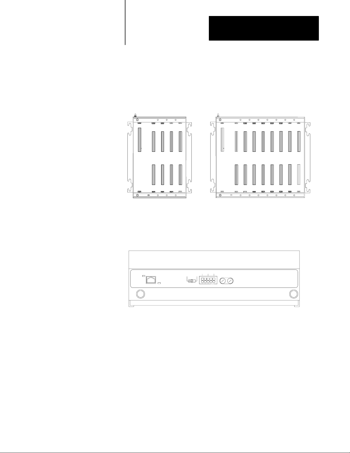
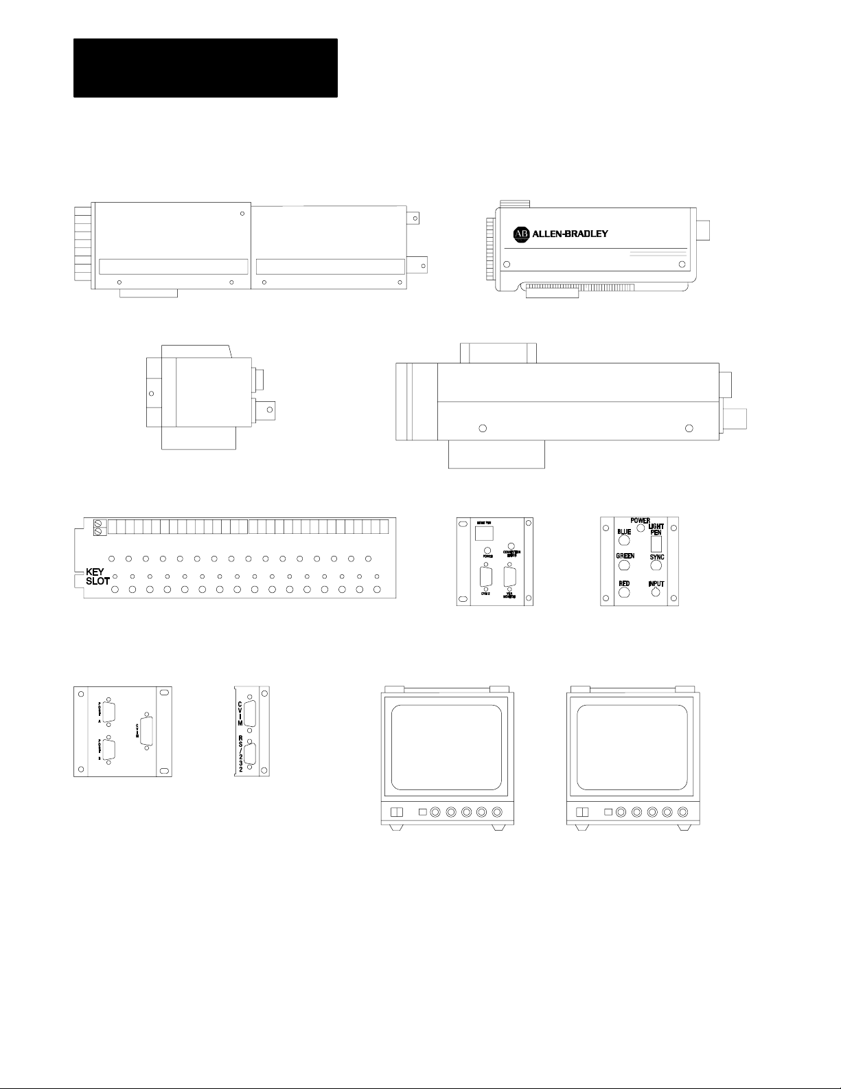
Identify the Hardware
After you unpack the hardware, use the figures below to help identify
the components.
Figure 1.1
Chassis
4slot chassis (5110A4/B) 8slot chassis (5110A8/B)
19775
Figure 1.2
Assembly
Fan
Fan
Cable
Status
100/200
V
ac
Fan Status
Fan assembly (5110FAN8)
220
Gnd L2/N L1
Vac
Fuse
15A 250V
Slow Blow
16725
1-3
Chapter 1
Preparing for Installation
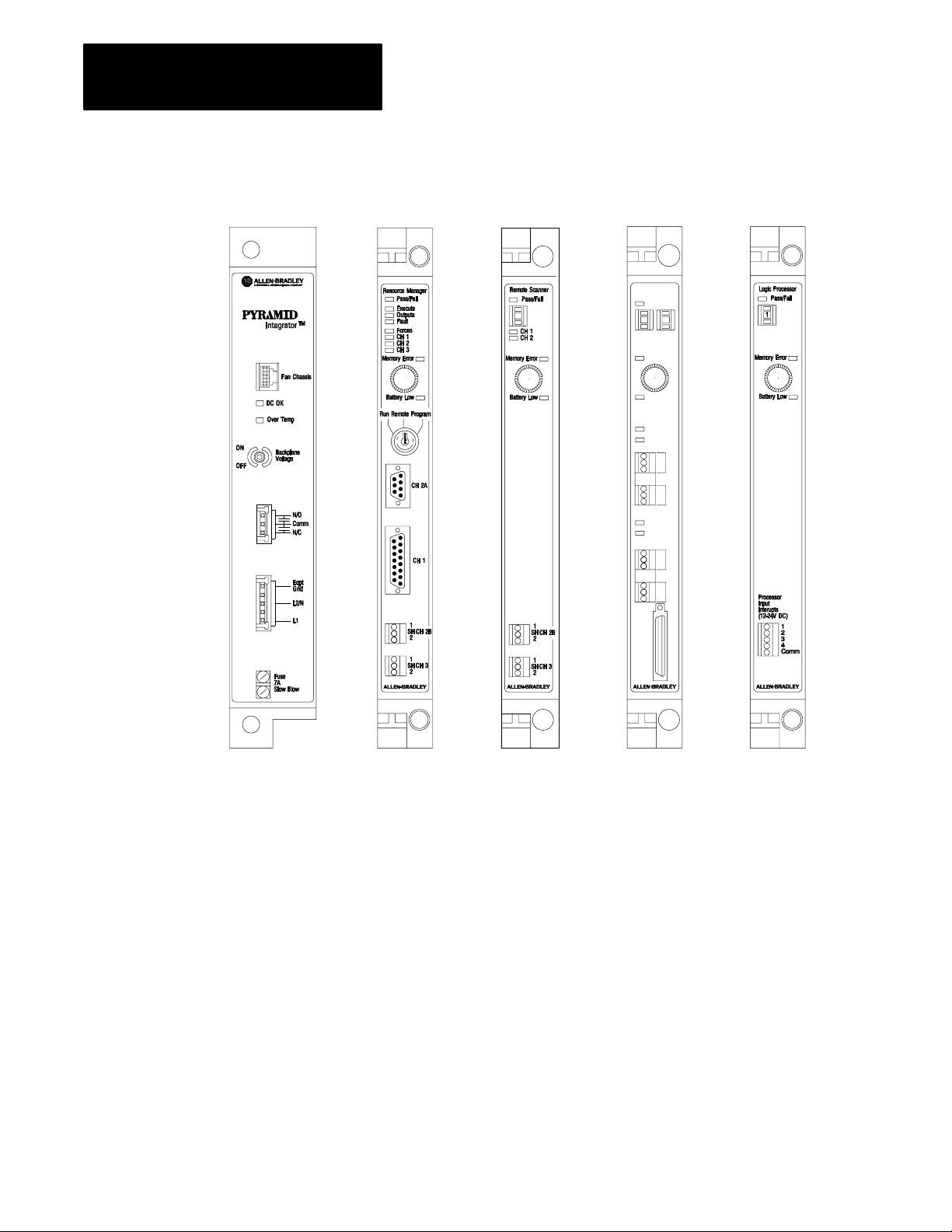
Figure 1.3
Modules
Remote/Local
Scanner
Pass/Fail
Scanner Range
Error
Battery Low
CH1
CH2
1
SH
2
1
SH
2
CH3
CH4
1
SH
2
1
SH
2
CH1
CH2
CH3
CH4
CH5
Power supply
(5120P1/B)
RM
(5130RM1, RM2)
RS2
(5150RS2)
CH5
RS5
(5150RS5)
LP
(5250LP1/B, LP2/B,
LP3/B, -LP4/B)
1-4
Chapter 1
Preparing for Installation
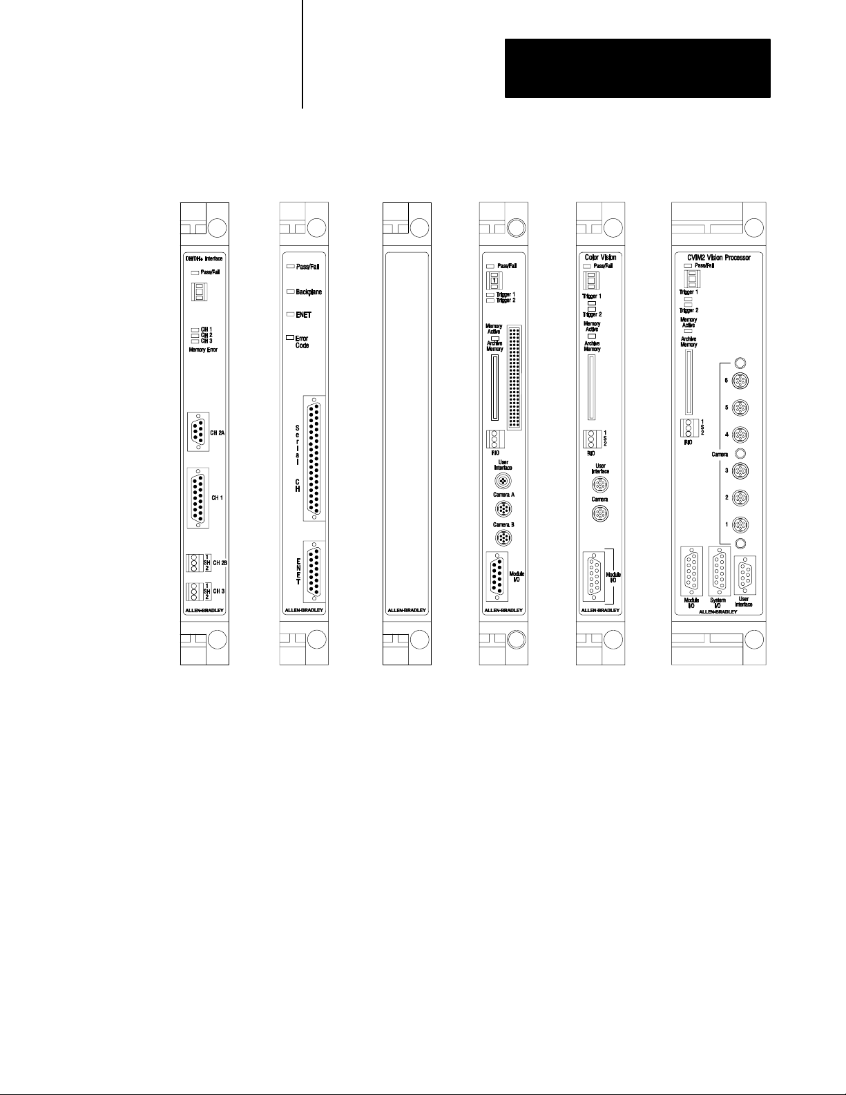
Figure 1.4
Modules
(continued)
KA module
(5130KA)
EI module
(5820EI)
Filler Plate
(5110FP)
CVIM module
(5370CVIM)
Color CVIM module
(5370CVIMC)
CVIM2 module
(5370CVIM2)
17185b
1-5
Chapter 1
Preparing for Installation
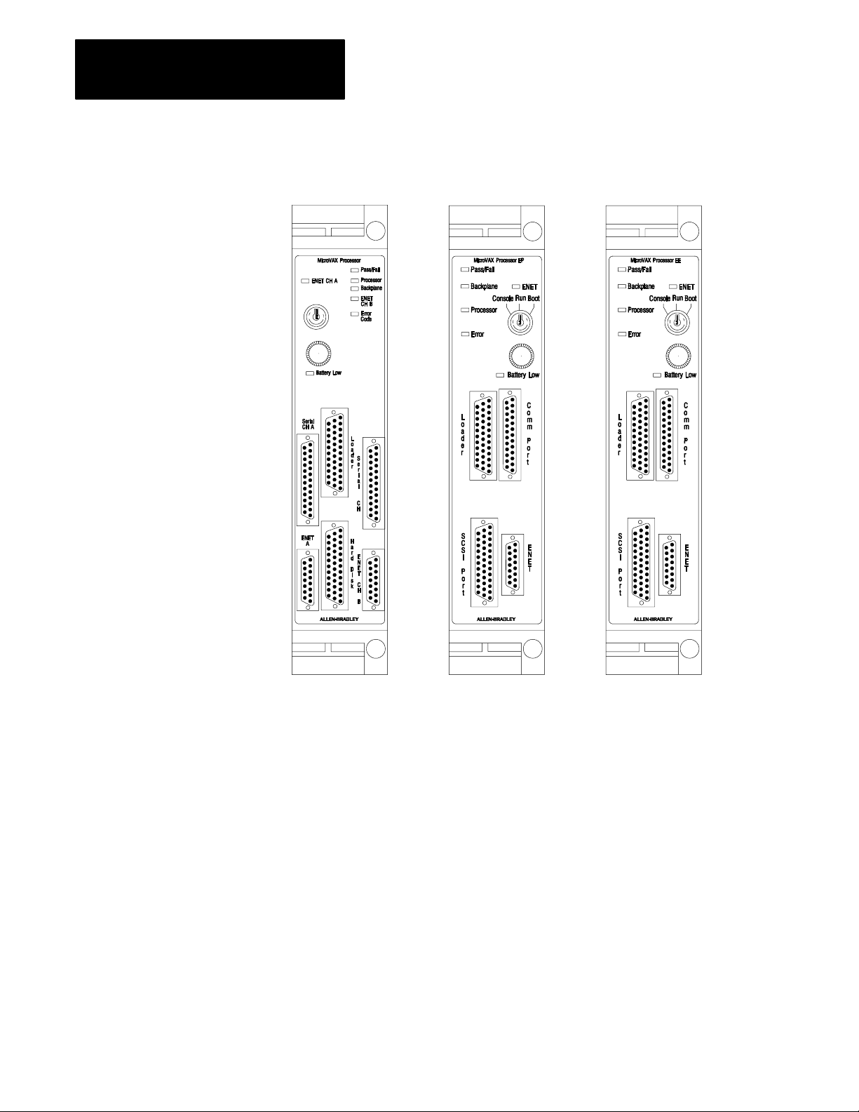
Figure 1.5
Modules
(continued)
1-6
MicroVAX Information
Processor (5730CPU1)
MicroVAX Information
Processor EP (5731CPU1)
MicroVAX Information
Processor EE (5731CPU2)
17185a
Chapter 1
Preparing for Installation
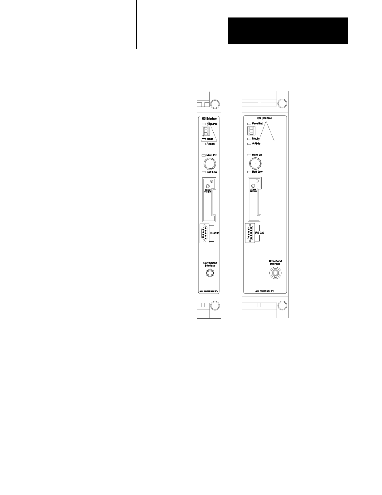
Figure 1.6
Modules
The cat. no. 5820CC
is used on an 802.4
carrierband network
(continued)
OSI Interface
Carrierband module
(5820CC)
OSI Interface
Broadband module
(5820CBx)
18395
1-7
Chapter 1
Preparing for Installation
Figure 1.7
Vision Components
Camera
(2801YD)
Camera
(2801YB)
I/O board
(1771JMB)
User interface box
(2801N26) for
CVIM2 only
Camera
(2801YC)
Camera
(2801YE)
User interface box
(2801N22)
I/O interface box
(2801N27)
1-8
I/O interface box
(2801N21)
Rack mount color monitor
(2801NB)
Black & white monitor
9" and 12"
(2801N9, N6, N20)
18784
Chapter 1
Preparing for Installation
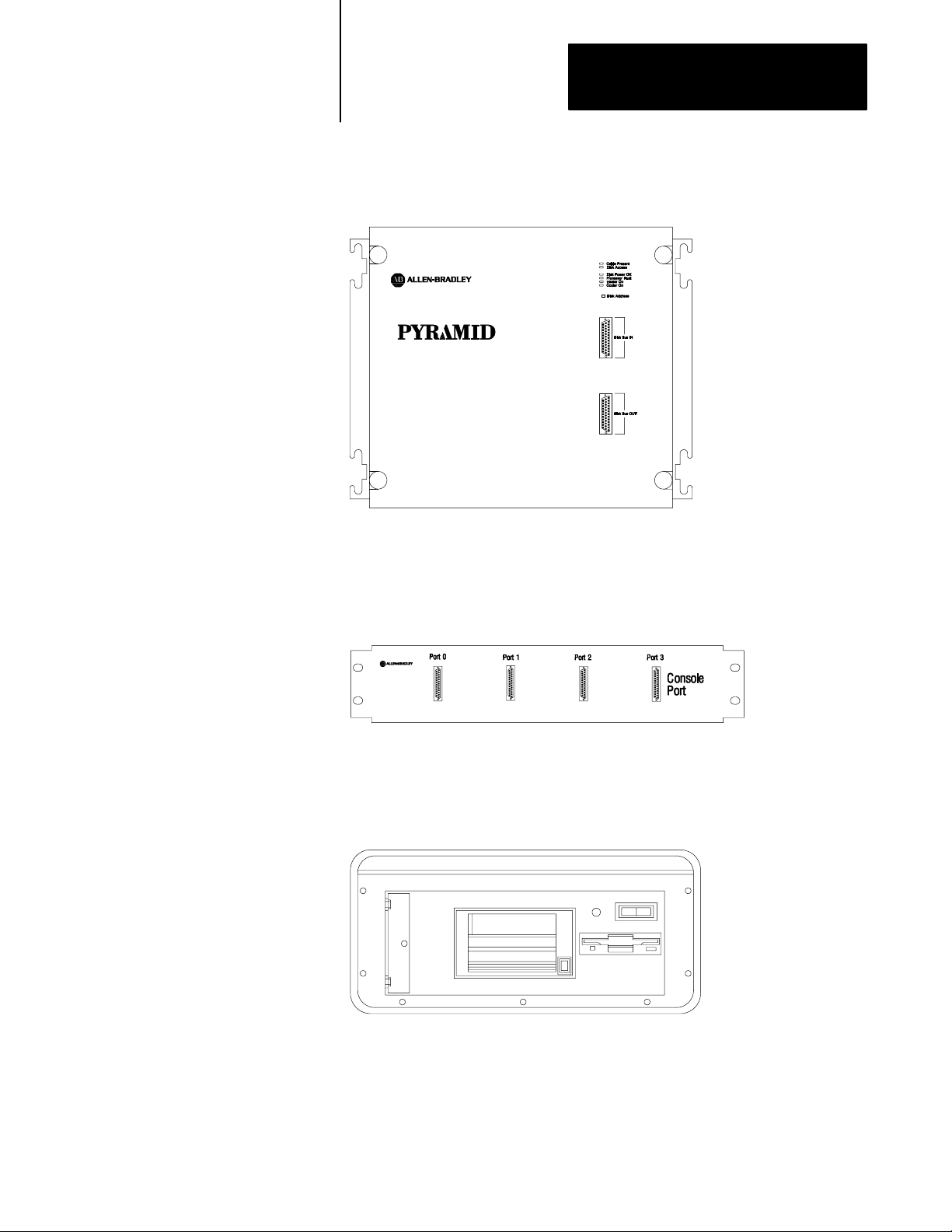
Figure 1.8
Industrial
Disk
159 / 209, 418, or 480 Mbyte industrial disk
(5730ID3 / 5710ID4, ID5, ID6, ID7)
Figure 1.9
Distribution Panel
4Port
18541
Figure 1.10
Program
Loader
4port distribution panel (5710DPI)
Program loader (5710PL/B)
17186
17188
1-9

Chapter 1
Preparing for Installation
Module Weights
Here are the weights of the PI modules, the fan assembly, industrial disks,
and the 4- and 8-slot chassis:
Module: Pounds: Kilograms:
RM 4 lbs, 4.0 oz 1.92 kg
LP 3 lbs, 13.5 oz 1.74 kg
RS2 3 lbs, 11.0 oz 1.67 kg
RS5 2 lbs, 15.6 oz 1.35 kg
MicroVAX Information Processor EP 8 lbs, 6.5 oz 3.81 kg
MicroVAX Information Processor EE 8 lbs, 6.5 oz 3.81 kg
MicroVAX Information Processor 9 lbs, 6.0 oz 4.24 kg
Ethernet Interface module 5 lbs, 3.0 oz 2.35 kg
CVIM module 3.70 lbs 1.68 kg
Color CVIM module 3.70 lbs 1.68 kg
CVIM2 module 7.97 lbs 3.62 kg
KA module 3 lbs, 11.0 oz 1.67 kg
OSI carrierband interface module 7 lbs 3.17 kg
OSI broadband interface module 8 lbs 3.62 kg
power supply 9 lbs, 10.0 oz 4.38 kg
fan assembly 11 lbs, 5.0 oz 5.12 kg
4slot chassis 5 lbs, 8.0 oz 2.5 kg
8slot chassis 12 lbs, 1.0 oz 5.48 kg
industrial disk (5710ID4, ID5, ID6, ID7) 58 lbs 26.24 kg
industrial disk (5730ID3) 63 lbs, 12 oz 28.95 kg
What to do Next
1-10
Go to chapter 2 to mount the components.

Chapter
Mounting the Components
2
Chapter Objectives
To Mount the System Components
Gather the Mounting Documentation
Read this chapter to learn how to mount various system components.
To mount the system components, complete the tasks below:
gather the mounting documentation
gather the PI components
gather the tools and supplies
rack mount the components and/or
panel mount the components
If your system includes the hardware below, also complete these tasks:
mount the fan assembly
mount the camera
mount the black and white monitor
Gather the mounting documentation. Check this documentation and
determine the:
components you are mounting
method of mounting to use (panel or rack)
position of the components
Gather the PI Components
Gather the PI components you will mount. If you are mounting any of the
following components, see either the rack or panel mounting procedure:
4-slot chassis
8-slot chassis
industrial disk
4-port distribution panel
I/O board for vision
I/O chassis and power supply
rack mount color monitor
If you are mounting the following hardware, go to page 2-8.
fan assembly
camera
black and white monitor
I/O interface box
user interface box
2-1
Chapter 2
Mounting the Components
Gather the Tools and Supplies
Rack Mount the Components
Gather these tools and supplies you will need:
#10-32 screws, lock washers, flat washers and screw driver set, if you
are rack mounting
#10-32 screws, lock washers, flat washers, and drill and tapping
equipment if you are panel mounting
wrench set, if applicable
wire brush
tape measure
marker or grease pencil
copper ground bus
two spacers, for use between the ground bus and panel
To: Then:
Panel mount the components go to page 25.
Rack mount the components continue reading.
After you have gathered the equipment, mounting documentation, and
tools, you are ready to mount the components.
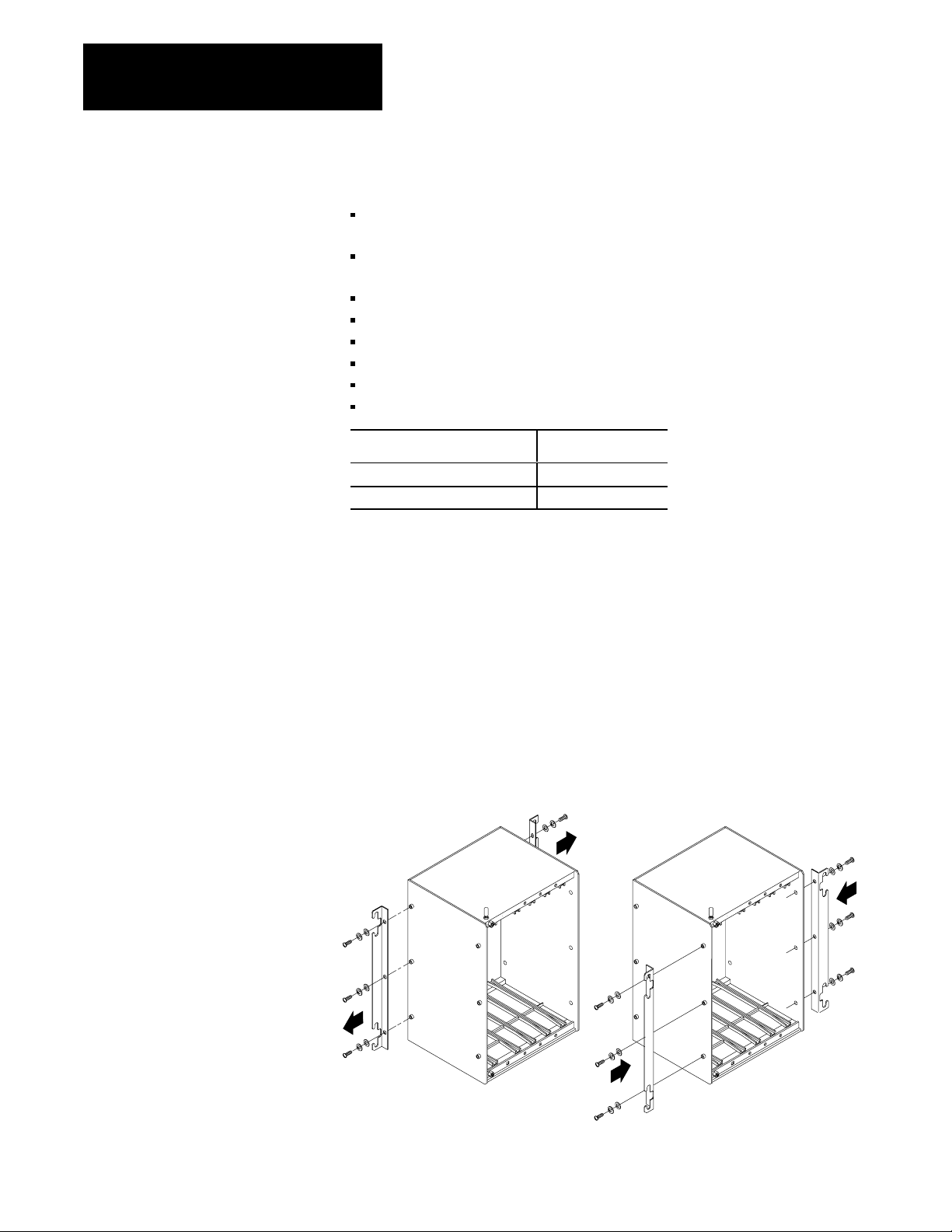
Follow these steps to rack mount the components.
1. Prepare each component.
For the 4- and 8-slot chassis, remove the brackets from the back of
the chassis, and install them on the front of the chassis for
rack mounting.
If you are using fan assembly, attach the fan assembly to the bottom
of the chassis and then mount the chassis to the rack or panel.
Remove brackets
Install brackets
19778
2-2
Chapter 2
Mounting the Components
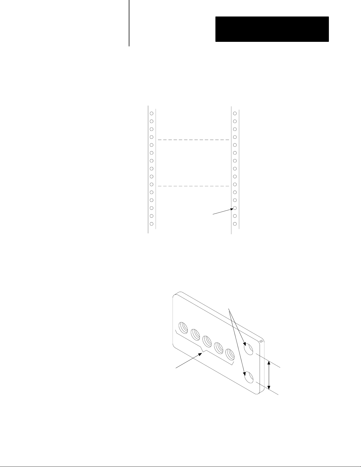
2. Prepare the rack.
Mark the position of each component you will mount. Make sure the
holes line up with the holes of the mounting brackets.
Planned position of
component on rack
#1032
Nominal
hole size
13220
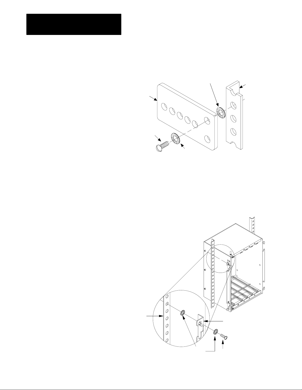
3. Mount a copper ground bus on the rack:
a. Drill two clearance holes for #10-32 mounting screws in the
bus. Drill and tap a #10-32 hole for each component you will
attach to the rack.
Drilled clearance
holes for mounting
Drilled and
tapped holes
Distance on rack
b. Prepare a mounting location for the bus as indicated by the
mounting diagram and as you did in step 2.
17171
2-3
Chapter 2
Mounting the Components
c. Attach the ground bus to the rack using the two drilled
mounting holes. One connection is shown below.
Star washer
Rack
Copper
ground
bus
#1032
screw
Star washer
4. Repeat this procedure for each component you mount:
a. Position the component on the spot you have prepared for it on
the rack.
b. Attach the component using #10-32 screws and lock washers.
Do not tighten the screws yet (you will tighten the screws after
you ground the components).
13235
2-4
Rack
Star
washers
Mounting bracket
#1032 screw
19779
Chapter 2
Mounting the Components
Panel Mount the Components
With the equipment, mounting documentation, and tools you are ready to
mount the components.
Follow these steps to panel mount the components.
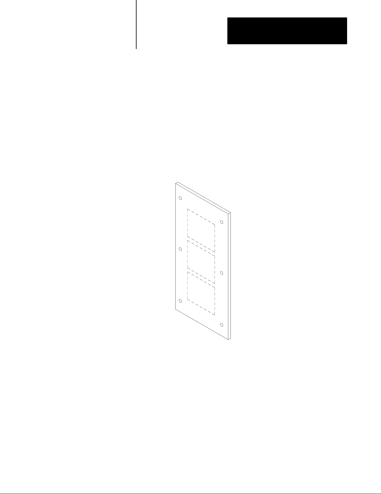
1. Prepare the panel:
a. Remove the panel from its enclosure and lay the panel flat, with
its front facing up.
b. Using the mounting worksheet from your system designer, mark
the location of the component on the panel for each component
you will mount.
Planned positions
of components
16731
2-5
Chapter 2
Mounting the Components
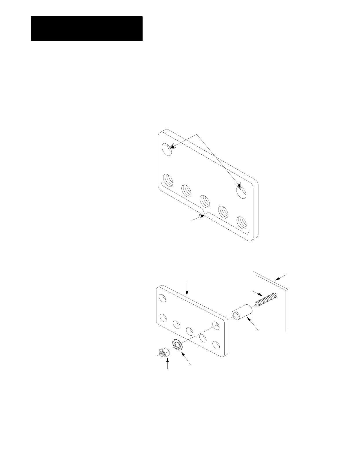
2. Prepare to attach the component to the panel: drill and tap a #10-32
hole through the panel at each point where component will attach.
3. Mount a copper ground bus on the panel:
a. Drill two clearance holes for #10-32 inch mounting screws in
the bus. Drill and tap a #10-32 hole for each component you
will mount on the panel.
Drilled clearance holes
for mounting
Drilled and
tapped holes
13234
b. Connect the ground bus to the panel using the mounting holes,
as shown below.
Panel
Ground bus
Screw
Conductive
metal spacer
13230
Nut
Start washer
2-6
Chapter 2
Mounting the Components
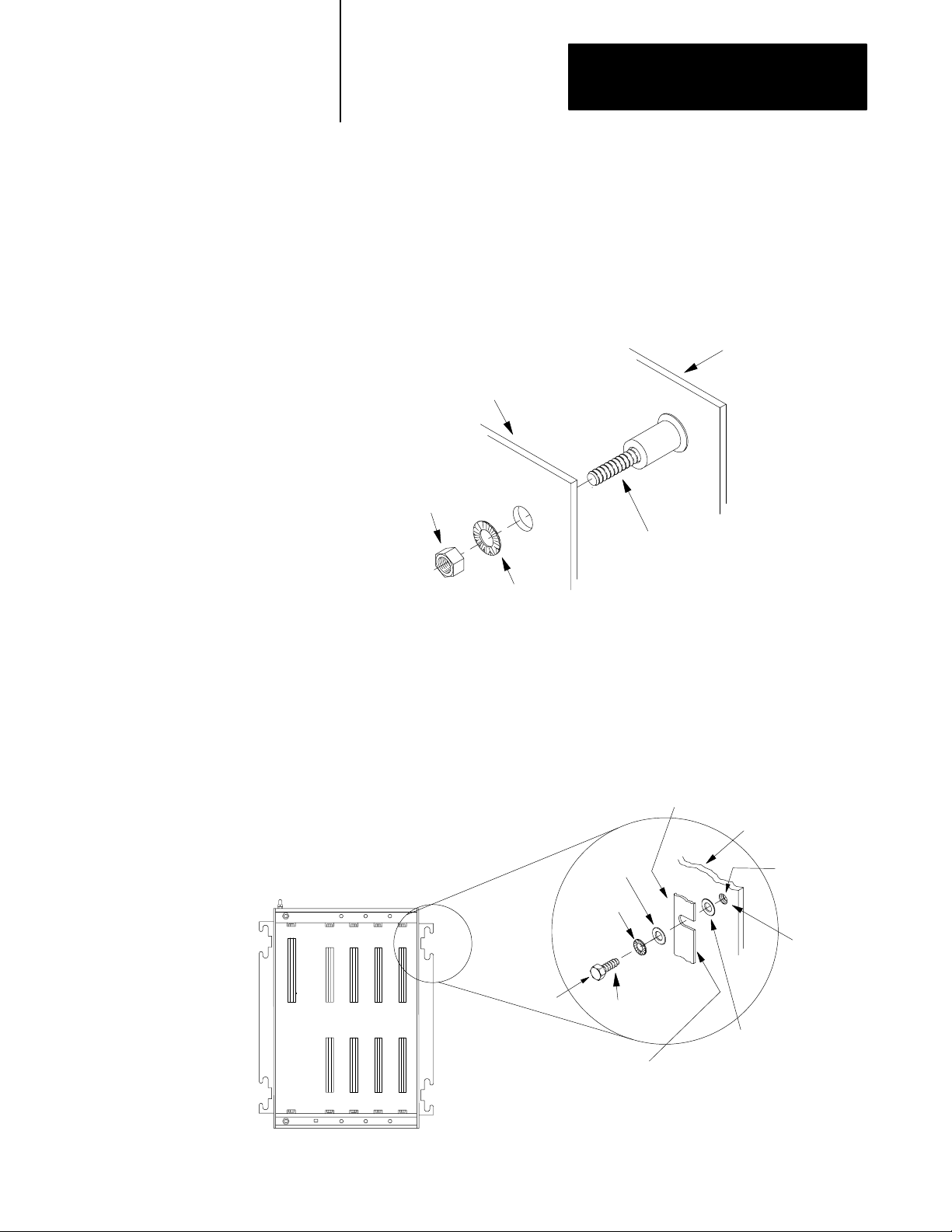
4. Return the panel to its enclosure:
a. Scrape paint and other nonconductive finishes from the shoulder
studs on the back wall of the enclosure. Scrape clear an area at
least as large as the washer to be used.
b. Attach the panel to the back wall of the enclosure as
shown here:
Back wall of
enclosure
Panel
Nut
Shoulder bolt on back
wall of enclosure
Star washer
13871
5. Repeat this procedure for each component you mount:
a. Position the component on the screws you have prepared for it
on the panel.
b. Attach the component to the panel as shown below. Do not
tighten the nuts yet (you will tighten the nuts after you have
completed grounding the component).
Mounting bracket
Back panel
Flat
washer
Star
washer
Tapped hole
Scrape paint
Bolt
If the mounting bracket is coated with
a nonconductive material (anodized,
painted, etc.), scrape the material
around the mounting hole.
#1032 screw
Flat
washer
16732
2-7
Chapter 2
Mounting the Components
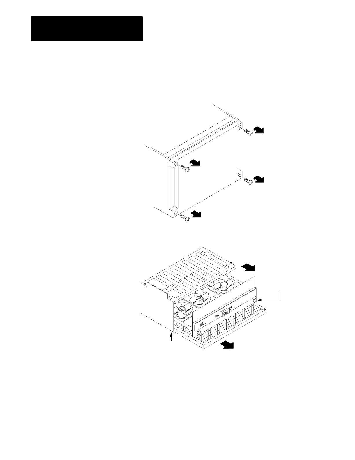
Mount the Fan Assembly
To mount the fan assembly, follow the steps below:
1. Remove the four screws in the bottom of the 8-slot chassis with a
phillips screwdriver.
16733
2. Remove the fan drawer and air filter from the fan cover.
b. Loosen the two screws on
bottom of the drawer and slide
the air filter from the fan cover.
a. Loosen the two screws
on the fan drawer and slide
the fan from the cover.
19780
2-8

Chapter 2
Mounting the Components
3. Attach the fan cover to the bottom of chassis:
a. Place the fan cover under the chassis. Make sure the screw holes
line up.
b. Place the four screws into the holes and tighten them.
4. Install the fan drawer:
19781
a. Slide the fan drawer into the fan
cover. Make sure the fan drawer
engages the rear edge of the fan cover.
b. Tighten the two captive screws.
19782
2-9

Chapter 2
Mounting the Components
5. Install the filter:
a. Make sure the air flow arrows on
the front of the filter are pointing up.
b. Align the filter with the two clips
at the bottom of assembly and slide
filter into the assembly.
Mount the Camera
19783
To mount a camera, follow the steps below.
1. Mount the camera on your own mounting bracket.
a. Design your bracket so that it:
does not cover any connectors
allows you to adjust the lens
holds the camera steady
attaches to the mounting holes on the camera
b. Mount the bracket in the indicated position in the
mounting documentation.
c. Attach the bracket to the camera.
2. Attach the optional camera enclosure, if your configuration has it.
2-10

Chapter 2
Mounting the Components
Mounting a Black and White
Monitor (2801N6,N9,N20)
Mounting the I/O Board
1771JMB
Check the mounting documentation to see how you should mount the black
and white monitor.
If mounting: Make sure:
on a table or shelf
• the connectors are accessible so you can connect the cables to the
monitor
• the table or shelf can hold the weight of the monitor
place the monitor in the position indicated by the mounting documentation.
on a shelf that
slides out of a rack
• to attach the slides and shelf to the rack by following the
documentation for the slides
• to place the monitor on the slides
a color monitor you follow the rack mounting procedure at the beginning of this chapter.
To mount the I/O board, attach the:
I/O interface box to I/O board and attach to mounting surface
user interface box to I/O board and attach to mounting surface
Attach I/O Interface Box
Attach the I/O interface box to the I/O board by following the steps below.
1. Locate the 50-pin connector on the side of the I/O board.
49
13
KEY
11
SLOT
1
0123456780
16903
2. Plug the I/O interface box’s 50-pin connector to the I/O board’s
50-pin connector.
C
V
I
M
R
S
/
2
3
2
49
13
11
1
KEY
SLOT
0123456780
3. Secure the I/O interface box and the I/O board to the mounting
surface using two screws.
16904
2-11

Chapter 2
Mounting the Components
Attach the User Interface Box
To attach the user interface box, follow the steps below:
1. Align the flange of the user interface with the two standoffs on the
bottom of the I/O board.
POWER
LIGHT
BLUE
PEN
What to do Next
910
11 12 14
13
GREEN
15
RED
SYNC
INPUT
16906
2. Secure the user interface and I/O board to the mounting surface using
two screws.
After you have mounted the components, go to chapter 3 to ground
the system.
2-12

Chapter
Grounding the Components
3
Chapter Objectives
To Ground the Components
Gather the Grounding Documentation
Gather the Necessary Tools and Supplies
Read this chapter to learn how to ground the components.
To ground the components, complete the following:
gather the grounding documentation from your system designer
gather the necessary tools and supplies
ground the components
Gather and check the grounding documentation to locate the point of each
component that you are to ground.
Important: The 4- and 8-slot chassis have a grounding stud located on the
top left front of each chassis. Use the grounding stud to ground the chassis.
Gather the following tools you will use to ground the chassis and camera:
8 AWG stranded wire or equivalent tinned braided cable (the exact wire
should be indicated on the grounding documentation from your
system designer)
screw driver set
a wire cutter/stripper
a quantity of #10-32 screws and ring terminals
3-1

Chapter 3
Grounding the Components
Ground the Components
Chassis
ground stud
Cup washer
#10 keps
nut
Follow the grounding documentation and the steps below to ground
the components.
1. Prepare and connect grounding conductors to the components.
a. Determine which mounting point on the chassis you are going to
use to ground the components (some chassis have grounding
lugs; for other chassis, you have to use a mounting screw).
b. Construct an equipment-grounding conductor for each
component. Make each one long enough to connect directly to
the ground bus. Keep the length to a minimum. Use the
specified wire and ring lugs.
c. Connect one end of each conductor to each component and
leave the other end loose, as shown below.
Mounting bracket
Star
washer
Using the mounting bracket for
chassis without grounding studs
for example, on the industrial disk.
Ring
Using
grounding lug
Mounting
screw
terminal
Flat
washer
Ring terminal
3-2
Star
washer
#10 hex
nut
19784
d. Tighten all mounting nuts or screws on the components.

Chapter 3
Grounding the Components
2. Prepare and connect grounding conductors to the ground bus:
a. Construct an equipment-grounding conductor long enough to
extend from the ground bus to an enclosure wall. Use 8 AWG
stranded wire or equivalent tinned braided cable copper wire
(the exact AWG should be in the grounding documentation from
the system designer) and ring terminals.
b. Construct a grounding-electrode conductor long enough to
extend from the bus to your grounding electrode system (earth
ground potential). Use 8 AWG copper wire (the exact AWG
should be in the grounding documentation from the system
designer) and ring terminals.
c. Connect the loose equipment-grounding conductors from step 1
and the two new conductors to the ground bus as shown below.
You can connect the conductors to the bus in any order.
Ground bus mounting
New
wires
Screw
Star washer
From component
Tapped hole
3. Connect the equipment-grounding conductor and
grounding-electrode conductor.
Ground bus
13271
a. Connect the equipment-grounding conductor to an enclosure
wall, as shown below.
b. Scrape paint and other non-conductive finishes from both sides
of the enclosure wall, at the point where the grounding
conductor will attach. Be sure to scrape clear an area at least the
size of the ring terminal to be used.
3-3

Chapter 3
Grounding the Components
Important: Make sure the scraped surface of the enclosure
wall is in contact with the total surface area of the ring terminal.
Enclosure wall
Ground
lug
Nut
Star
washer
Scrape paint
Scrape paint on enclosure wall
and use a star washer.
Equipmentgrounding
conductor
Bolt
10020
c. Connect the grounding electrode conductor to your grounding
electrode system (earth ground potential). We recommend a
direct earth ground for maximum protection.
ATTENTION: Do not use an indirect earth ground,
such as a water pipe, building structure, or power distribution
system, otherwise your components may experience grounding
problems.
What to do Next
3-4
After you have grounded the components, go to chapter 4 to continue
installing your system.

Installing the Modules
Chapter
4
Chapter Objectives
How to Use this Chapter
Help to Prevent Electrostatic Damage
This chapter shows you how to install each module and is divided into
sections that cover the installation tasks for each module.
Use this chapter with the completed module worksheets from the PI
Design Manual (5000-6.2.1) to perform various installation tasks for each
module. The worksheets contain specific settings and connections for each
module. This chapter describes how to make those settings and
connections. Also, it guides you to additional connection information for
the module.
After you have used the worksheets to install the modules, we suggest you
keep them with the system for future reference.
To install a PI module in a chassis, see appendix A.
When you:
remove the modules from the protective bags
set the jumpers or switches inside a module
change memory boards
Do so in a static-safe environment. As a minimum, we recommend the 3M
Type 8005 Portable Field Service Grounding Kit or its equivalent for
providing a static-safe environment.
Lithium Battery Information
ATTENTION: If you perform operations on a module
improperly, you may cause an electrostatic discharge, which can
damage the module. Perform internal operations, such as setting
the jumpers, only in a static-safe environment.
PI modules that come with a lithium battery are:
MicroVAX Information Processor
LP
RM
RS
OSI interface module
4-1

Chapter 4
Installing the Modules
Disposing of a Lithium Battery
ATTENTION: Do not incinerate or dispose of lithium batteries
in general trash collection. Explosion or violent rupture
is possible.
Follow these guidelines when you dispose of the module’s battery.
Important: Check your state and local regulations that deal with the
disposal of lithium batteries.
Do not: Because the battery:
dispose of lithium batteries whose combined
weight is greater than or equal to 1/2 gram
in general trash collection
incinerate or expose the battery to high
temperatures
solder the battery or leads could explode
open, puncture, or crush the battery could explode and toxic, corrosive, and
charge the battery could explode or the cell might overheat and
short positive or negative terminals together will heat up
ship on passenger aircraft could become dangerous
ship while connected to equipment could become dangerous
could become dangerous
could explode
flammable chemicals could be exposed
cause burns
Batteries should be collected for disposal in a manner to prevent short
circuiting, compacting, or destruction of case integrity and hermetic seal.
For disposal, batteries must be packaged and shipped, in accordance with
transportation regulations, to a proper disposal site. The U.S. Department
of Transportation authorizes shipment of “lithium batteries for disposal” by
motor vehicle only in regulation 173.1015 of CFR49 (effective Jan. 5,
1983). For additional detailed information, contact:
4-2
U.S. Department of Transportation
Research and Special Programs Administration
400 Seventh Street., S.W.
Washington, D.C. 20590
Although the United States Environmental Protection Agency at this time
has no regulations specific to lithium batteries, the material contained in
the battery may be considered toxic, reactive, or corrosive. The person
disposing of the material is responsible for any hazard created in doing so.
State and local regulations may exist regarding the disposal of
these materials.

Chapter 4
Installing the Modules
Emergencies
Emergencies can occur due to the battery’s makeup.
Major components of the cell are: And these components are:
lithium metal highly reactive in water, flammable, and can create
toxic fumes when burned.
inorganic electrolyte thionyl chloride
(SOCI2)
fast evaporating, corrosive, has a pungent odor, reacts
violently to water, causes burns on contact, and
produces toxic and corrosive fumes and chemicals
upon decomposition.
Storing Lithium Batteries
To avoid hazardous situations, follow the guidelines below:
store in a cool, dry environment; typically 20 to 25° C (68 to 77° F) and
40 to 60% relative humidity
replace the batteries at least every two years
do not store used batteries longer than three months before disposal
use a first-in/first-out system for handling the batteries
clearly mark the contents of the storage area
do not smoke in the storage area
regularly monitor the temperature and humidity of the storage area
storage area should be well-ventilated and fire-protected; it should have
a system that automatically detects fires, extinguishes fires, and
activates an alarm signal
Personnel Protection
Safety equipment should be available and personnel should be equipped
with self-contained breathing apparatus, safety shields, safety goggles, and
protective clothing when they have to handle overheated or
leaking batteries.
Overheated Battery
When a lithium battery is overheated, explosion or violent rupture is
possible. Attempt to eliminate any external source of heat. If connected to
equipment, un-power the equipment. After cooling, remove the battery to
a well-ventilated fire-protected area.
4-3

Chapter 4
Installing the Modules
Leaking Battery
If the hermetic seal of the case is broken, ventilate the area. Using tongs,
scoop, or shovel, remove the leaking battery to a well-ventilated
fire-protected area.
Fire
ATTENTION: Do not use water or carbon dioxide (CO2) fire
extinguishers on the fire. Lithium is reactive with
these substances.
As described for overheated batteries, explosion or violent rupture is
possible. If a cell is ruptured, the exposed lithium is combustible and is
reactive in water. If lithium is burning, use a Class D Powder fire
extinguisher or smother with a graphite powder, such as Lith-X, or an
appropriate metal fire extinguishing powder, applied with a long-handled
tool. Avoid exposure to toxic fumes from burning lithium.
Gather the Module Documentation
Gather the module documentation and check to see which modules you are
installing. See Table 4.A for which page you should go to for
the procedures.
Table 4.A
Installing
If you are installing this module: See page:
power supply (5120P1/B) 45
RM (5130RM1,RM2)
KA module (5130KA)
RS (5150RS2, RS5) 415
LP (5250LP1,LP2,LP3,LP4) 418
vision processor (5370CVIM, CVIM2, CVIMC) 420
MicroVAX Information Processor module
(5730CPU1, 5731CPU1, CPU2)
EI module (5820EI) 424
OSI carrierband interface module (5820CC) 426
OSI broadband interface module (5820CBx) 426
PI Modules
48
421
4-4

Chapter 4
Installing the Modules
ATTENTION: If you have any empty slots in the chassis,
install filler plates (5110-FP) in them. Otherwise, the modules
could be damaged. To install filler plates, see appendix A.
Many of the connections you make to the modules are made to connectors
that you wire. If you do not know how to wire these connectors, see
appendix A.
Important: Save the packing material in case you have to ship a module.
Power Supply
To install the power supply, complete the following tasks:
set the power supply operating voltage
install the power supply in the chassis
make connections to the power supply
Set the Operating Voltage Switch (115 or 230V ac)
Follow the steps below to set the operating voltage.
Important: You do not have to remove any covers to set the
operating voltage.
For 5120P1/B
(Front)
230V
(Bottom view)
1.
Locate the red voltage selector switch
inside the bottom of the power supply.
2.
Set the switch to either 230V or 115V.
The switch is factory set at 230V ac.
115V
Install the Power Supply in the Chassis
The installation procedure for the power supply is similar to other PI
modules, see “Installing a PI Module in the Chassis” in appendix A to
install the power supply in the chassis.
17204
4-5

Chapter 4
Installing the Modules
If you have this configuration: Make this connection: With this cable: Go to this step:
Connect the Fan Assembly/External Power Source
If you have a fan assembly or are connecting the power supply to an
external power source, make this connection. If you don’t have to make
this connection, go to the next section. To make this connection, follow
the steps below.
1. Determine which fan assembly and/or power source connections you
are making.
PI chassis with MicroVAX Information Processor
and no vision processor
PI chassis with a MicroVAX Information Processor
and at least one vision processor
•PI chassis with more than two vision processors
•At least one vision processor, PLC5/250
controller and no MicroVAX
Information Processor
2. Connect the 5120-CP1 cable to the fan chassis and the power supply.
a. Gather the fan status cable that
came with the fan assembly.
b. Connect the rightangle connector
of the fan status cable to the port
labeled FAN CHASSIS on the
power supply.
c. Route the fan status cable away
from the Interlock Relay and Line
Voltage connectors.
power supply to fan assembly cat no. 5120CP1 2.
power supply to fan assembly and
external power source
power supply to external power source cat no. 5120CP3 4.
cat no. 5120CP2 3.
5120CP1
4-6
d. Connect the straight end of the
cable to the port labeled FAN
STATUS CABLE on the fan chassis.
19785

Chapter 4
Installing the Modules
3. Connect the 5120-CP2 cable to the fan chassis, the power supply
and a 24V external power supply.
a. Connect the spade lugs to
an external 24V power supply.
Connect triple red to +.
Connect triple
black to -.
Connect single red
to + sense or +.
Connect triple red to +.
Connect triple
black to -.
Connect single black
to - sense or -.
b. Connect the rightangle
connector of the 5120CP2
cable to the port labeled FAN
5120CP2
CHASSIS on the power supply.
c. Route the cable away from
the Interlock Relay and Line
Voltage connectors.
d. Connect the straight end of
the cable to the port labeled
FAN STATUS CABLE on the
fan chassis.
4. Connect the 5120-CP3 cable to a 24V external power supply.
a. Connect the spade lugs
to an external 24V power
supply.
b. Connect the rightangle
connector of the 5120CP3
cable to the port labled
5120CP3
FAN CHASSIS on the
power supply.
c. Route the cable away
from the Interlock Relay
and Line Voltage
connectors.
19786
Connect single red
to + sense or +.
19787
Connect single black
to - sense or -.
Connect to Interlock Relay
See chapter 9 to connect the interlock relay.
Connect to Line Voltage
See chapter 10 to connect ac power.
4-7
Chapter 4
Installing the Modules
RM/KA Module
To install the RM/KA module, use the worksheets as guides and complete
the following:
set the RM/KA module switches and jumpers
install the module in the chassis
install the battery (RM only)
set the KA module address
make connections to the module
set the keyswitch (RM only)
Set the RM/KA Module Switches and Jumpers
Set the RM/KA module switches and jumpers to configure:
switch bank 1 (communication parameters)
switch bank 2 (station address)
jumpers 9 and 10 (termination resistor)
jumpers 5-8 (channel 1 interface)
ATTENTION: If you perform operations on a module
improperly, you may cause an electrostatic discharge, which can
damage the module. Perform internal operations, such as setting
the jumpers, only in static-safe environment.
Channel 1 is factory set to RS-232. You do not have to remove the
memory board unless you are changing the channel 1 interface.
4-8

Chapter 4
Installing the Modules
Follow the steps below to set the jumpers and switches.
Set Switch Bank
1. Set switch bank 1 as shown on the worksheet for the RM/KA module.
Switch bank 1 (communication channel)
Top of RM/KA module
(Front)
SB1
Up
(away from board)
12345678
SB1
Down (toward board)
17078
2. Set switch bank 2 as shown on the worksheet for the RM/KA module.
Switch bank 2 (station address)
Top of RM/KA module
(Front)
SB2
Up
(away from board)
12345678
SB2
Down (toward board)
17079
4-9

Chapter 4
Installing the Modules
Set Jumpers 9 and 10
Set jumpers 9 and 10 as shown on the worksheet for the RM/KA module.
Jumpers JP9 and JP10 (termination resistor)
Bottom of RM/KA module
(Front)
CH2
CH3
123
JP9
123
JP10
17080
Set Jumpers 5 through 8
Set jumpers 5 through 8 as shown on the worksheet for the RM/KA
module.
Jumpers JP5 to JP8 (channel 1 interface)
Module
(Front)
Memory module
4-10
CH1
1
2
3
JP5 JP6 JP7 JP8
17081

Chapter 4
Installing the Modules
Install the RM/KA Module
Install the RM/KA module as shown in appendix A.
Install the Battery (RM only)
1. Unscrew the battery holder from the module.
2. Insert the battery (that came with the module) into the holder as
shown below.
+ (positive)
- (negative)
16913
3. Screw the battery holder (with battery inserted in holder) into the
module. Make sure you do not overtighten the battery holder.
When you first install the RM, it powers up with a red fault LED
illuminated. You have to clear memory with 6200 software or
INTERCHANGE software or re-download a previously saved PLC-5/250
configuration to clear this LED. You must clear this LED before you can
use the PLC-5/250 processor.
4-11

Chapter 4
Installing the Modules
Set the KA Module Address
Follow the steps on the next page to set the KA module address. The
address must start at 1 for the first interface module and be consecutive for
the other interface modules up to 4.
KA module
1
1. Locate the pushwheel on the front panel of the
KA module.
2. Set the pushwheel as indicated on the worksheet.
Setting the pushwheel:
To: Push the:
decrease the number
increase the number
top button
bottom button
17973
Connect the RM/KA Module
The table below lists what you can connect to the RM/KA module:
You can connect the module to: Using channel:
RM KA module
programming terminal 2A 2A
RS232, RS422, RS423 devices (terminal or modem) 1 1
DH link 2B or 3 2B or 3
DH+ link 2B or 3 3B or 3
4-12
Check the appropriate worksheet for the RM/KA module to see which
connections to make. To connect a programming terminal, see chapter 5.
To connect an RS-232, RS-422 or RS-423 device to channel 1, follow
these steps.
1. Depending upon the type of device you are connecting, use the pin
assignments in Table 4.B through Table 4.D to construct a cable.

Chapter 4
Installing the Modules
Table 4.B
Pin Assignments
RS232
Pin: Input to RM or KA/output from
1
Description:
RM or KA module:
1 not applicable chassis ground
2 output transmitted data
3 input received data
4 output request to send
5 input clear to send
6 input data set ready
7 na signal ground
8 input received line signal detector
20 output data terminal ready
1
Complies
with the RS232 standard as a DTE typeD interface.
Table 4.C
Pin Assignments
RS422
Pin: Input to RM or KA/output from
1
Description:
RM or KA module
1 na chassis ground
2 output transmitted data
14 output transmitted data
1
3 input received data
16 input received data
1
4 output request to send
19 output request to send
1
5 input clear to send
13 input clear to send
1
6 input data set ready
22 input data set ready
1
7 na signal ground
8 input received line signal detector
10 input received line signal detector
20 output data terminal ready
23 output data terminal ready
1
Compatible
with RS422 equipment as long as a pointtopoint connection is used.
1
1
4-13

Chapter 4
Installing the Modules
Table 4.D
Pin Assignments
RS423
Pin: Input to RM or KA/output from
1 na chassis ground
2 output transmitted data
3 input received data
4 output request to send
5 input clear to send
6 input data set ready
7 na signal ground
8 input received line signal detector
14 not applicable send common
16 na receive common
20 output data terminal ready
1
Compatible
RM or KA module:
with RS423 standard for the signals used.
1
Description:
2. Connect the device as shown below.
KA module
RM
To connect computer to KA CH1:
a. Attach the usersupplied cable to
the device.
b. Locate the port labeled CH1 on
the module.
c. Attach the cable from the device to
the port.
d. Secure the connector.
To connect computer to RM CH1:
Programming
terminal
16748
4-14

Chapter 4
Installing the Modules
To connect to DH or DH+ link, follow the steps below.
KA module
RM
1. Locate the connectors labeled CH 2B and/or CH3.
2. (Option) Unplug the 3pin connector and wire using
Twinaxial cable (cat. no. 1770CD).
3. Reattach the wired connector to the port.
Shield 2
Blue 1
Clear 3
16749
RS Module
Set the Keyswitch (RM only)
Set keyswitch in the position indicated on the worksheet.
To install the RS, use the worksheets as guides and complete the following:
configure the termination resistors (RS2 only)
install the RS in the chassis
install the battery
set the RS module address
connect the RS to I/O
Configure the Termination Resistor (RS2 only)
This section tells you when to use:
internal 150-Ohm termination resistors for RS2 (Figure 4.1)
external 82-Ohm termination resistors (supplied with 5150-RS2)
Use Table 4.E to configure your termination resistors for RS2.
4-15

Chapter 4
Installing the Modules
Table 4.E
T
Configure
If the transmission rate is: And the scanner is physically located: Then put the internal 150Ohm
57.6k bit/s or 115k bit/s middle of remote I/O link out position
230k bit/s middle of remote I/O link out position
ermination Resistors for the RS2
terminationresistor jumper in the:
end of remote I/O link in position
end of remote I/O link out position, and attach 82Ohm termination
resistor between pins 2 and 3
Figure 4.1
Internal 150Ohm T
RS2
(Front)
ermination Resistors
RS2 (internal 150Ohm termination resistor)
Module
Memory module
4-16
Termination
Resistor
CH JMPR IN OUT
1 E1 3 2 1 3 2 1
2 E2 3 2 1 3 2 1
17085
Install the RS
Install the module as shown in appendix A.

Chapter 4
Installing the Modules
Install the Battery
To install the RS battery, see “Install the Battery” section on page 4-11
for instruction.
Set the RS Module Address
Follow the steps below to set the RS module address. For RS2, the address
must start at 1 for the first RS and be consecutive for the other RS modules
up to 4.
For RS5, the address can be spread among the RS modules, or all four
addresses may be used on one RS5. The addresses must be consecutive.
RS5
Connect
14
1. Locate the pushwheel on the front panel of the RS.
2. Set the pushwheel as indicated on the worksheet.
Setting the pushwheel:
To: Push the:
decrease the number
increase the number
top button
bottom button
I/O
19788
To connect remote I/O to the ports labeled CH 1 to CH 4, and local I/O to
CH5, see chapter 7.
The RS5 pushwheels: Is equivalent to:
14 four RS2 modules' pushwheels.
11 one RS2 module's pushwheel.
4-17

Chapter 4
Installing the Modules
LP Module
To install the LP, use the worksheet as a guide and complete the following:
install the LP
install the battery
set the LP module address
make connections to the module
Install the LP
See appendix A to install the module in the chassis.
Install the Battery
To install the LP battery, see “Install the Battery” section on page 4-11
for instructions.
Set the LP Address
Follow the steps below to set the LP module address. The address must
start at 1 for the first LP and be consecutive for the other LP modules up
to 4.
LP
1
1. Locate the pushwheel on the front panel of the LP.
2. Set the pushwheel as indicated on the worksheet.
Setting the pushwheel:
To: Push the:
decrease the number
increase the number
top button
bottom button
16751
4-18
Chapter 4
Installing the Modules
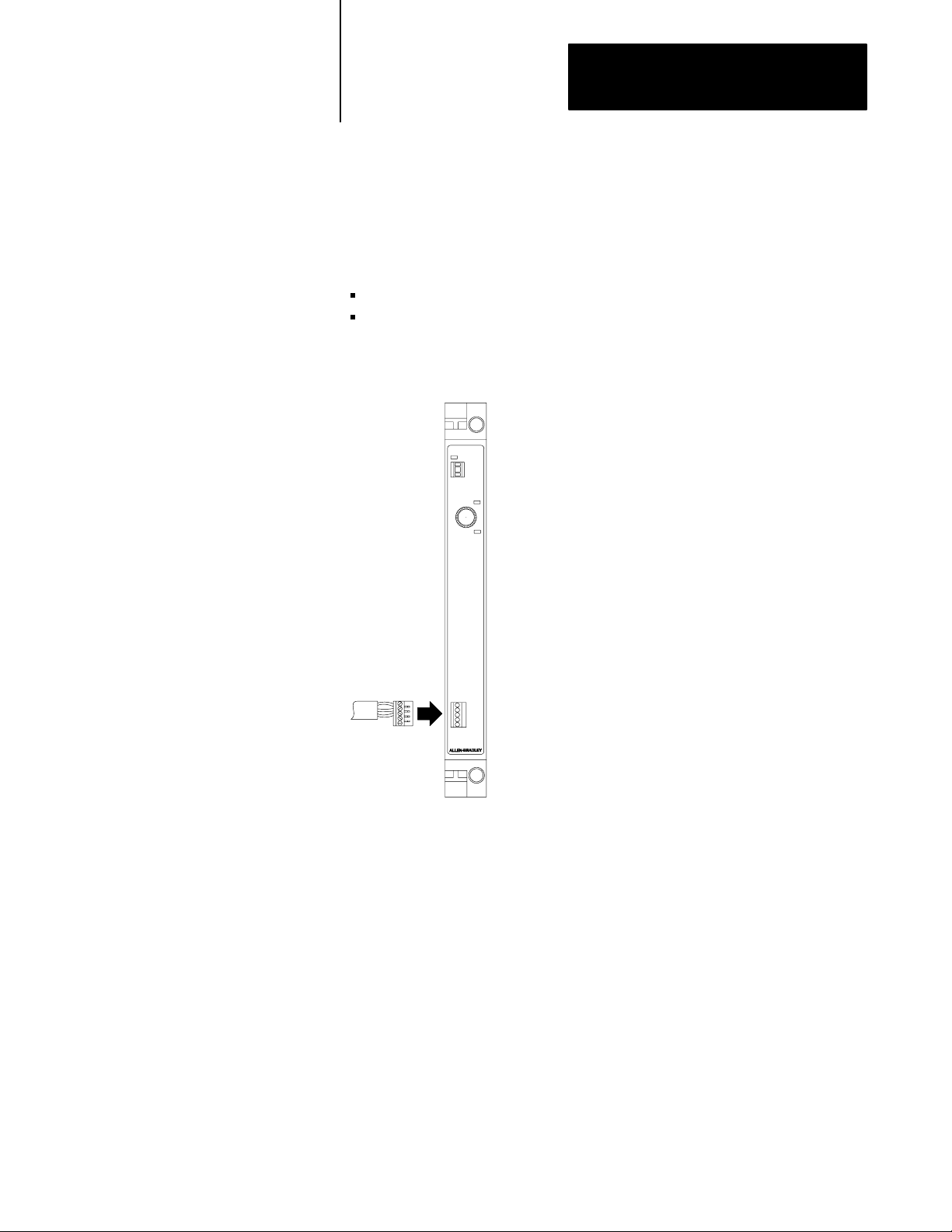
Connect Processor Input Interrupts
Check the worksheet to see if you have to make this connection. If you do
not have to make this connection, go to the next section. If you have to
make this connection, use:
14-28 AWG wire
strip .276” (7mm) insulation from the wire
Follow the steps belows to connect the Processor Input Interrupts.
LP
1. Remove the connector on the port labeled
PROCESSOR INPUT INTERRUPTS and wire it
as shown on the worksheet.
2. Plug the wired connector into the port labeled
PROCESSOR INPUT INTERRUPTS.
3. Connect the other end of the wire as shown in
the worksheet or the wiring diagrams from your
system designer.
16752
4-19

Chapter 4
Installing the Modules
Vision Processor Modules
To install the CVIM module, CVIM2 module and Color CVIM module,
use Worksheet 2.2 as a guide and complete the following:
set the switch for camera power
install the vision processor module in the chassis
set the module address
make connections to the module
Set Switch for Camera Power
Before you install the module, set the switch for camera power. It is
factory set for +/– 12 volts. If you are using an external power supply for
the camera, set the switch to +24 volts as shown below.
Back of a CVIM module
+24
±12
±12 factory setting
If using external power
supply for camera, put
switch in +24 position.
17087
Install the CVIM Module
See appendix A to install the module in the chassis.
4-20

Chapter 4
Installing the Modules
Set the Module Address
Follow the steps below to set the module address.
1
1. Locate the pushwheel on the front panel
of the CVIM module.
2. Set the pushwheel as indicated on
Worksheet 2.2.
Setting the pushwheel:
MicroVAX Information Processors
To: Push the:
decrease the number
increase the number
top button
bottom button
16753
There are other connections to make to the vision processor modules. To
continue installing the vision components, see chapter 6.
Important: If you have a RM with firmware revision A04 or earlier and
you’re replacing a MicroVAX Processor, go to the section “Replace a
MicroVAX Processor” on page 4-24.
To install the MicroVAX Information Processor, use the appropriate
worksheet as a guide and complete the following:
install the processor in the chassis
install the battery
set the keyswitch
connect Ethernet and make other connections to the module
replace the module (if applicable)
Install the Processor
See appendix A to install the processor in the chassis.
4-21

Chapter 4
Installing the Modules
Install the Battery
To install the MicroVAX Information Processor battery, see “Install the
Battery” section on page 4-11 for instruction.
Set the Keyswitch
Set the keyswitch as indicated on the processor’s worksheet.
MicroVAX Information
Processor EP or EE
Console
Select: To:
CONSOLE
RUN
BOOT
halt module and use diagnostic
console monitor
normally operate the module
reset the module
Run
MicroVAX Information Processor
Boot
16754
4-22

Chapter 4
Installing the Modules
Connect Ethernet
To connect the processor to Ethernet, follow these steps:
MicroVAX Information ProcessorMicroVAX processor EE or EP
1. Run the Ethernet cable to the processor as indicated
in your system designer wiring diagrams.
2. Locate the port on the processor labeled ENET CH #
(for MicroVAX Information Processor EE or EP) or
ENET CH A (for MicroVAX Information Processor)
and attach the Ethernet cable to the port.
3. Secure the connector.
ATTENTION: The Ethernet connection must be secure while
the PI system is controlling equipment; otherwise, the
MicroVAX Information Processor may shut down the system’s
power supply.
If the system power shuts down, follow these steps:
1. Make sure the Ethernet connection is secure.
2. Cycle power by turning off the power from the power supply and
turning it on again.
Make Connections to the Processor
To make the following connections to the processor, see chapter 5.
the 4-port distribution panel
the program loader
an industrial disk
16755
4-23

Chapter 4
Installing the Modules
Replace a MicroVAX Information Processor
If you have a RM with firmware revision A04 or less and you are replacing
a 5730-CPU1 processor with either a MicroVAX Information Processor EE
or EP, or an EI module, follow the steps below.
1. Save the program image with the original module installed.
2. Power the system down.
3. Remove the module you are replacing.
4. Restore power.
5. Clear memory using 6200 series software.
6. Power the system down.
7. Install the new processor.
EI Module
8. Restore power.
9. Restore the saved image to the PI system.
Important: If you have a RM with firmware revision A04 or earlier and
you’re replacing a 5730-CPU1 processor with an EI module, go to the
above section “Replace a MicroVAX Information Processor.”
To install the EI module, complete the following:
install the EI module in the chassis
connect Ethernet and make other connections to the module
check jumper settings
replace the module (if applicable)
Install the EI Module
See appendix A to install the module in the chassis.
4-24

Chapter 4
Installing the Modules
Connect Ethernet
To connect the module to the Ethernet, follow the steps below.
1. Run the Ethernet cable to the processor as indicated in your
system designer wiring diagrams.
2. Locate the connector on the EI module labeled ENET and
attach the Ethernet cable to the connector.
3. Secure the connector.
18543
Important: If you’re not using a powered transceiver, make sure the
Ethernet connection is secure before cycling power.
ATTENTION: The Ethernet connection must be secure while
the PI system is controlling equipment; otherwise, the EI
module may shut down the system’s power supply.
If the system power shuts down, follow these steps:
1. Make sure Ethernet connection is secure.
2. Cycle power by turning off the power from the power supply and
turning it on again.
Ethernet Heartbeat
The EI module requires the IEEE 802.3 SQE (Signal Quality Error) test
(also known as Ethernet heartbeat). Make sure your Ethernet transceiver is
set with the SQE test enabled. For more information about the SQE test,
see the documentation that came with your transceiver.
4-25

Chapter 4
Installing the Modules
ATTENTION: Do not use a transceiver that has a disabled
SQE test to connect an EI module to an Ethernet network
because it could disrupt network activity.
Check Jumper Settings
The jumpers on the EI module are factory set. Make sure the jumpers are
set as shown below.
OSI Carrierband/Broadband Interface Module
(Front)
123
JP3
123
JP2
Top of EI module
123
JP1
123
JP0
18544
To install the OSI interface module, use the worksheets as guides and
complete the following:
set the switches
install the module in the chassis
install the battery
set the pushwheel
make connections to the module
4-26
Set the OSI Interface Switches
Set the OSI interface module’s switches for:
operating modes (switch 1)
communication defaults (switch 2)
ATTENTION: If you perform operations on a module
improperly, you may cause an electrostatic discharge, which can
damage the module. Perform internal operations, such as setting
the jumpers, only in static-safe environment.

Chapter 4
Installing the Modules
Follow these steps to set the switches.
Important: Set the switches before you put the module in the chassis and
power up.
Set Switch Bank
1. Set switch 1 as shown on the worksheet.
Switch 1 (operating modes)
Top of OSI Interface module
(Front)
Up
(away from board)
Down (toward board)
1234
18414
2. Set switch 2 as shown on the worksheet.
Switch 2 (use defaults)
Top of OSI Interface module
Up
(away from board)
Down (toward board)
1234
Important: Leave switches 3 and 4 in the up position.
Install the OSI Interface Module
(Front)
18415
Install the module as shown in appendix A.
Install the Battery
To install the OSI interface module battery, see page 4-11.
4-27

Chapter 4
Installing the Modules
Set the OSI Interface Module Pushwheel Address
Follow the steps below to set the OSI interface module’s pushwheel
address. If you have more than one OSI interface module in the same
chassis, set the pushwheels sequentially; make sure you set the first OSI
interface module’s pushwheel to 1.
1
1. Locate the pushwheel on the front panel of the
carrierband or broadband Interface modules
2. Set the pushwheel as indicated on the worksheet.
Setting the pushwheel:
To: Push the:
decrease the number
increase the number
top button
bottom button
18385
Connect the OSI Interface Module
The table below lists what you can connect to the OSI interface module.
You can connect the module to: Using connector/port:
AB MAP Station Manager
(communicates locally as well as through the network)
PLC3 controller
PI system
Thirdparty device
carrierband or broadband
4-28
Check the worksheet to see which connections to make. To connect to a
programming terminal running A-B MAP Station Manager software, see
chapter 5. To connect an RS-232 device, follow the steps below and see
Figure 4.2.

Chapter 4
Installing the Modules
1. Using the pin-outs in the table below, construct a cable depending
upon the type of device you are connecting. The OSI interface
module’s RS-232 port is configured as a DCE port.
RS232C
Pin: Signal:
1 reserved. The reserved signals are for future use and shouldn't be wired to.
The OSI Interface's RS232 port does not supply a shield connection.
2 TXD
3 RXD
4 reserved
5 signal ground
6 reserved
7 reserved
8 reserved
9 reserved
Figure 4.2
Assignments for the 9Pin RS232 Connector
Pin
RS232 port
Carrierband
module
Broadband
module
9
8
7
6
5
4
3
2
1
18394
2. If you want to use a shielded RS-232 cable, wire the shield:
at the other end of the cable or
via an RS-232 connector with a metal hood
4-29

Chapter 4
Installing the Modules
3. Connect the device as shown below.
Programming terminal
Carrierband
module
To connect to carrierband/broadband, follow the steps below.
Carrierband
module
Broadband
module
18391
Broadband
module
4-30
1. Run the MAP cable to the module.
2. Locate the connector on the module
labeled BROADBAND or CARRIERBAND
and attach the MAP cable to the connector.
3. Secure the connector.
For more information on broadband or carrierband cabling specifications,
call General Motors Photographic (313) 422-2900 and ask for:
MAP/TOP Broadband Specification
MAP/TOP Carrierband Specification

Chapter 4
Installing the Modules
Important: These are not A-B publications.
Configuring the PI OSI Interface Module
This section shows you how to configure the OSI interface module.
You need:
a programming terminal that has already been configured as an A-B
MAP Station Manager
a RM that has been configured using the information in chapter 3
PI OSI interface module software (cat. no. 5820-OS)
Allen-Bradley MAP Station Manager Software User’s
Manual (6630-6.5.2)
Pyramid Integrator OSI Interface Software User’s Manual (5820-6.5.1)
Figure 4.3
Interface Module Communication Ports
OSI
The cat. no. 5820CC is
used for on an 802.4
carrierband network.
RS232
Carrierband
Interface
Carrierband
module
Broadband
module
Broadband
Interface
18390
4-31

Chapter 4
Installing the Modules
Broadband versions of the OSI interface module transmit and receive on
the following frequency channel pairs:
Cat. no.: MAP channel: Transmit channel: Transmit frequency: Receive channel: Receive frequency:
5820CBA A 3'/4' 59.75 - 71.75 MHz P/Q 252 - 264 MHz
5820CBB B 4A'/5' 71.75 - 83.75 MHz R/S 264 - 276 MHz
5820CBC C 6'/FM1 83.75 - 95.75 MHz T/U 276 - 288 MHz
OSI Interface
To install the OSI interface module, complete the following:
make sure slot time is consistent with other nodes on the 802.4 network.
A-B defaults to 80 decimal (50 HEX)
perform system load
check default settings
specify switch settings (see chapter 7 of the PI Design Manual
(5000-6.2.1) for more information.)
Slot Time
The default slot time is 80 decimal (50 HEX). To change slot times:
use the local interface capability of A-B MAP Station Manager
see A-B MAP Station Manager Software User’s Manual
see PI OSI Interface Software User’s Manual
System Load
See both the A-B MAP Station Manager Software User’s Manual and the
PI OSI Interface Software User’s Manual for information on
system loading.
4-32
Configurable Parameters
All OSI-related configurable parameters have factory-default settings that
work for most networks. If you need to change any of these default
settings, see:
A-B MAP Station Manager Software User’s Manual
PI OSI Interface Software User’s Manual

Chapter 4
Installing the Modules
Specify Switch Settings on the OSI Carrierband/Broadband
Interface Module
Switch: Position: Description:
1 up if there is a valid image in nonvolatile memory, the OSI interface module will enter fully operational
mode after:
• a power cycle, regardless of the mode preceding the power cycle
• you enter a reset command from the AB MAP Station Manager, regardless of the mode
preceding the reset
• you enter a change mode to Fully Operational from the AB MAP Station Manager
if there is not a valid image in nonvolatile memory, the OSI interface module will not enter fully
operational mode but will enter Partially Operational mode.
down the OSI interface module will enter partially operational mode after:
• a power cycle, regardless of the mode preceding the power cycle
• you enter a reset command from the AB MAP Station Manager, regardless of the mode
preceding the reset
• you enter a change mode to Partially Operational from the AB MAP Station Manager
2 up the OSI interface module uses user defaults, if available, at powerup or reset (see the PI OSI Interface
Software User's Manual for a list of user defaults). If user defaults aren't available, the interface will
use AB communication defaults.
down the OSI interface module uses AB communication defaults at powerup or reset.
3 preset at AB reserved (do not change)
4 preset at AB reserved (do not change)
Important:
Keep switches 3 and 4 in the up position; otherwise, the PI system stays in a power cycle.
4-33

Chapter
Installing the Peripherals
5
Chapter Objectives
Where to Begin
This chapter describes how to install the following peripherals:
programming terminal
209, 418, or 480 Mbyte industrial disk (5710-ID4, -ID5, -ID6, -ID7)
159Mbyte industrial disk (5730-ID3)
4-port distribution panel (5710-DPI)
program loader (5710-PL/B)
The table below lists the page numbers for installation procedures.
To complete installation of: See page:
programming terminal 51
industrial disk 52
4port distribution panel 59
program loader 59
If you are installing an industrial disk and/or a distribution panel, make
sure you have mounted and grounded these components as shown in
chapters 2 and 3.
Important: Save the packing material in case you have to ship a disk.
Install a Programming Terminal
If you are connecting a programming terminal to the RM, follow
these steps.
1. Install a DH+ Interface Board (cat. nos. 1784-KT,-KTK1) in the
programming terminal.
2. Use the appropriate interconnect cable to connect the interface board
to the terminal as shown below. For more information on
interconnect cables, see appendix C.
5-1

Chapter 5
Installing the Peripherals
To connect a programming terminal to RM/KA module, follow these steps.
Programming terminal
RM
Install the Industrial Disk
16773
To install the industrial disk, perform the following tasks:
set the operating voltage
set the address (for 5710-ID4, -ID5 only)
wire an out-of-temperature shutdown warning device (optional)
wire the industrial disk for ac power
connect the industrial disk to the MicroVAX Information Processors
connect the industrial disk to second industrial disk (optional)
connect a terminator on the last disk
5-2

Chapter 5
Installing the Peripherals
Remove the Front Panel
To set the operating voltage and wire the disk you have to access the inside
of the industrial disk’s chassis. To access the inside of the industrial disk’s
chassis, remove the front panel as shown below.
Industrial disk Unscrew the four
captive screws
and remove the
front panel.
16758
Set the Operating Voltage and SCSI Address
The operating voltage is factory set to 230V ac and can be changed to
115V ac.
To set the: On: See:
operating voltage 5730ID3, 5710ID6, 1-ID7 Figure 5.1
operating voltage and address 5710ID4, ID5 Figure 5.2
Figure 5.1
Operating Voltage on a 159Mbyte Industrial Disk
Set
1. Locate the operating voltage switch.
2. Set the switch to the operating voltage of your
system (the switch is shipped set to 230V ac and
can be changed to 115V ac).
16759
5-3

Chapter 5
Installing the Peripherals
Figure 5.2
Operating Voltage and Address on a 209Mbyte or 418Mbyte
Set
Industrial Disk
5710ID4
0
5710ID5
0
or
1
1. Locate the operating voltage switch.
2. Set the switch to either 230V or 115V.
The switch is factory set at 230V ac.
3. Set ID4 address to 0.
ID5 address to 0 and 1.
Important: Set each disk to a unique address.
18537
ATTENTION: The 5710-ID6 has SCSI bus address preset to 0
and 1. The 5710-ID7 has SCSI bus address preset to 2 and 3.
These values are not configurable.
Wire an OutofTemperature Warning Device
If you are not going to wire this device, you can skip this section. Check
the disk information from your system designer. It should tell you if you
are going to make this connection and if so, what device you are going
to connect.
Important: For industrial disk cat. no. 5730-ID3, this function is not
available on early revisions with part numbers 532029301 and 532029302.
If the disk’s external environment temperature falls below 0
60
°C and remains so, you have no less than 9 minutes to orderly shut down
the system. After 9 minutes, the disk shuts itself down and data may
be lost.
°C or exceeds
5-4

Chapter 5
Installing the Peripherals
The signal is an open collector output capable of sinking 48ma. The signal
is low true when:
the disk’s external environment temperature is below 0°C or above 60°C
the processor that controls the disk drive’s environment has faulted
Follow the steps below to wire a warning device.
1. Locate the terminal strip labeled N.C.,
OT WARNING L, OT WARNING RET on
the front of the disk.
2. Wire the terminal strip as indicated below:
Wire terminal: To:
1
2
3
3. Connect the other end of the wires to the
appropriate device.
no connection
OT WARNING L
OT WARNING RET
16760
Wire the Disk for ac Power
The disk connects to ac power. The input ranges for the disk are:
90 to 132V ac or 180 to 264V ac
47 to 63 Hz
Follow these steps to wire the disk for ac power. Do not connect the other
end of the cable to ac power yet. You will make that connection in
chapter 9.
1. Locate the terminal block labeled L1, L2/N,
GND on the front of the disk.
2. Wire the terminal strip as indicated below:
Wire terminal: To:
L1
L2/N
GND
* Do not wire if you used a chassis ground.
L1
L2 Neutral
Equip GND*
16761
5-5

Chapter 5
Installing the Peripherals
Reattach the Front Panel
You can now re-attach the front panel of the disk as shown below.
Place the panel over the
front of the chassis and
tighten the thumbscrews.
16762
Connect the MicroVAX Information Processors
Connect the disk to the MicroVAX Information Processor as shown in
Figure 5.3 or Figure 5.4. Connect either a one meter cable (5710-SDC) or
a two meter cable (5710-SSA).
Figure 5.3
Connecting
Industrial disk (5730ID3)
1. Attach the one end of the cable (5730IDC) to the port
labeled DISK BUS IN on the disk.
a 159Mbyte Industrial Disk
MicroVAX Information Processor
5-6
2. Attach the other end of the cable to the port labeled
HARD DISK on the MicroVAX Information Processor.
16763

Chapter 5
Installing the Peripherals
Figure 5.4
Connecting
1. Attach the one end of the cable to the port labeled DISK BUS IN
2. Attach the other end of the cable to the port labeled SCSI PORT
3. If you are only connecting one disk, a terminator (5710SSC)
a 209Mbyte, 418Mbyte or a 480Mbyte Industrial Disk
Industrial disk (5710-ID4, ID5, ID6, ID7)
Terminator
on the first disk.
on the MicroVAX Information Processor EE or EP.
must be placed in the port labeled DISK BUS OUT.
MicroVAX
Information
Processor EE
or EP
18535
Connect Second Disk
Check your documentation to see if you are to connect a second disk.
If you are: Then:
Connecting a second disk follow the steps below.
Not connecting a second disk go to the next appropriate section.
Connect either a one meter cable (5710-SDC) or a two meter
cable (5710-SSA).
5-7

Chapter 5
Installing the Peripherals
Do
this if you are
connecting a
159Mbyte industrial
disk to the MicoV
AX
Information Processor
Industrial disk (5730ID3)
1. Attach the one end of the cable
(5730IDC) to the port labeled
DISK BUS OUT on the first disk
2. Attach the other end of the cable to the port
labeled DISK BUS IN on the second disk.
Do
this
if you are
connecting a
209Mbyte,
418Mbyte, or a
480Mbyte
industrial disk to
the MicoV
AX
Information
Processor
3. Secure the connectors.
16764
Industrial disk (5710ID4, ID5, ID6, ID7)
1. Attach the one end of the cable to
the port labeled DISK BUS OUT
on the first disk.
2. Attach the other end of the cable
to the port labeled DISK BUS IN
on the second disk.
3. Secure the connectors.
5-8
4. Then attach the terminator
(5710SSC) to the port labeled
DISK BUS OUT on the second disk.
Terminator
18536

Chapter 5
Installing the Peripherals
Install the 4Port
Distribution Panel
To connect the 4-port distribution panel, follow the steps below.
1. Route the cable from the back of the distribution panel to the
information processor.
2. Using the following pin-outs table to construct a cable for the device
that will connect to the panel.
Port 0 Port 1 Port 2 Port 3
Pin Signal Pin Signal Pin Signal Pin Signal
2 TXD0 2 TXD1 2 TXD2 2 TXD3
3 RXD0 3 RXD1 3 RXD2 3 RXD3
7 SIG GND 7 SIG GND 4 RTS2
5 CTS2
6 DSR2
7 SIG GND
8 DCD2
20 DTR2
22 RI
1
5731CPU1
and 5731CPU2 do not support line signals.
1
1
1
1
7 SIG GND
Install the Program Loader
3. Connect the cable to the MicroVAX Information Processor ’s port
labeled Comm Port (5731-CPU-1, CPU-2) or Serial CH A
(5730-CPU1).
4. Connect the device to the distribution panel.
a. Attach one end of the cable you made to the appropriate
connector on the distribution panel (port 3 is the console port).
b. Attach the other end of the cable to the device.
The program loader connects to the MicroVAX Information Processor.
Connect the program loader before you boot the system. To connect the
program loader, follow the steps below.
1. Plug in the program loader.
2. Run the cable with the 50-pin, D-shell connector from the program
loader to the MicroVAX Information Processor.
3. Connect the 50-pin, D-shell connector to the port labeled LOADER
on the MicroVAX Information Processor.
For more information on the program loader, see the Program Loader
Installation Data (5000-2.93).
5-9

Chapter 5
Installing the Peripherals
What to do Next
After you have completed installing the peripherals,
If you are installing: Go to chapter:
vision components 6
I/O 7
5-10

Chapter
6
Installing the Vision Components
Chapter Objectives
Installing the Vision System
Before You Begin
This chapter shows you how to install your vision components. If you are
not installing a vision system, go to the next chapter.
To complete the installation of your vision components, you connect the:
I/O interface box
user interface box
camera to the CVIM module
I/O board
CVIM module to a remote I/O link (optional)
Make sure you have mounted and grounded the following components as
shown in chapters 3 and 4:
monitor (2801-N6,-N8,-N9,-N20)
I/O board (1771-JMB)
I/O interface box (2801-N21)
user interface box (2801-N22)
6-1

Chapter 6
Installing the Vision Components
Connect the I/O Interface Box
To connect the I/O interface box (2801-N21) to the CVIM module, follow
these steps:
CVIM module
1. Connect the cable (2801NC17) to the CVIM port
labeled MODULE I/O.
2. Run the cable to the CVIM as indicated in the
wiring documentation.
3. Connect the cable to the port labeled CVIM on the
I/O Interface box.
I/O interface box
16774
6-2

Chapter 6
Installing the Vision Components
Connect the User Interface Box
To connect the user interface box (2801-N22) to the:
CVIM module
color monitor (2801-N8) or black and white monitor
(2801-N6, -N9,-N20)
light pen (2801-N7)
CVIM Module
To connect the CVIM module, follow these steps:
1. Connect the cable (2801NC18) to the CVIM port
labeled USER INTERFACE.
2. Route the cable to the user interface as indicated
in the wiring documentation.
3. Connect the cable to the port labeled INPUT on the
user interface.
User interface
POWER
BLUE
GREEN
RED
LIGHT
PEN
SYNC
INPUT
16775
6-3

Chapter 6
Installing the Vision Components
Color Monitor
To connect the color monitor, follow the steps below.
Color monitor
1. Connect each of the four colorcoded cables into its
port on the monitor (connect the white cable to the port
labeled SYNC).
2. Route the cables to the user interface.
3. Connect the other end of each cable into
corresponding port on the user interface.
POWER
LIGHT
BLUE
PEN
User interface
GREEN
SYNC
RED
INPUT
16776
Black and White Monitor
To connect the black and white monitor, follow the steps below:
Black and white monitor
1. Plug the cable into the monitor's port
VIDEO
IN
labeled VIDEO IN.
2. Route the cable to the user interface.
3. Plug the other end of the cable into the
user interface's port labeled GREEN.
6-4
User interface
POWER
LIGHT
BLUE
PEN
GREEN
SYNC
INPUT
RED
16901

Chapter 6
Installing the Vision Components
Light Pen
To connect the light pen, connect the light pen’s cable to the user
interface’s port labeled LIGHT PEN as shown below.
Light pen
User interface
POWER
LIGHT
BLUE
PEN
GREEN
SYNC
INPUT
RED
16902
Connect the Camera to the CVIM Module
To connect the camera to the CVIM module, follow the steps below.
Follow this procedure for each camera you connect to the CVIM module.
CVIM module
1. Connect the cable to the module.
If connecting
camera:
2801YB
2801YC
2801YD
2. Route the cable from the VISION
PROCESSOR to the camera as
described in the wiring information.
Use one of these cable:
2801NC5, NC6, NC7
2801NC13, NC14, NC15, NC16
2801NC15, NC16, NC17
Camera
Back of
camera A
3. Connect the cable to
the camera.
16779
6-5

Chapter 6
Installing the Vision Components
Connect the I/O Board
You can connect up to 16 I/O modules to the I/O board (1771-JMB).
Check your vision documentation to see which connections you have to
make and follow the steps below.
1. Gather the I/O modules you are to install.
49
13
KEY
SLOT
11
1
2 connectors for
trigger inputs
0123456789
0
14 connectors for
general outputs
10
11 12 14
13
15
16899
2. Attach each I/O module to the I/O board.
1. Push the I/O module into its
connectors (see your system
designer vision information).
2. Using a phillips screwdriver,
secure the connection by
tightening the module's screw.
DIMENSIONS
(
(MILLIMETERS)
INCHES
16900
3. Wire the terminal strip as indicated in your system designer vision
documentation.
6-6

Chapter 6
Installing the Vision Components
Connect to Remote I/O Link
If you have to make this connection, use the steps below to attach the cable
to the module using Belden 9463 cable.
1. Remove the male connector for the port labeled RIO
and wire it as shown below:
Shield
Blue2
Clear 1
2. Plug the wired connector into the processor's
female connector labeled RIO.
3. Route the cable to the adapter as shown in the
wiring documentation.
4. Attach the other end of the cable to the adapter.
16781
What to do Next
After completing the installation of your vision components,
If you are: Go to chapter:
Installing I/O 7
Not installing I/O 8
6-7

Installing 1771 I/O
Chapter
7
Chapter Objectives
What You Should Have Completed
Before You Begin
This chapter guides you in installing your I/O. It shows you how to:
set the I/O chassis switches
set the I/O chassis configuration jumper
set the I/O adapter module switches
install keying bands and wiring arms
install I/O modules
connect wiring arms
connect your I/O to the RS module
If you are not installing I/O modules, go to the next chapter.
Make sure you have mounted and grounded your I/O chassis and power
supply as shown in chapters 2 and 3 of this manual.
Gather the I/O information from the system designer (including the
worksheet). This information should contain:
switch settings for the I/O chassis and modules
the names of the I/O modules to install and where to install them
(chassis, rack)
the I/O to wire
identification for each I/O
the I/O channel connections to make
You may also need the specific publication for each type of I/O module
you are installing.
7-1

Chapter 7
Installing 1771 I/O
Set I/O Chassis Switches
On (toward board)
12345678
Off
(away from board)
On the 1771-A1B, -A2B, -A3B, -A3B1, -A4B chassis set the backplane
switches to determine:
last state (switch 1)
processor restart lockout (switch 2)
type of addressing (switches 5 and 6)
Set these switches before you install the adapter module.
1. Locate the eight switches located on the left side of the
chassis backplane.
2. Using the worksheet, set the I/O chassis switch assembly as indicated
with a ball-point pen (Figure 7.1). Do not use a pencil because the tip
can break off and jam or short the switch.
Figure 7.1
Switches on the I/O Chassis
Set
Last State
On
Off
Outputs of this I/O chassis remain in their last state when a fault is
detected by this I/O adapter
1
.
Outputs of this I/O chassis are turned off when a fault is
detected by this I/O adapter.
Always
Always
Processor Restart Lockout
On
On
Off
On
1
A
TTENTION:
chassis remain in their last state to allow machine motion to continue. W
OFF
2
The 1771AS adapter does not support 1slot or 1/2slot addressing. When you use this adapter
and 6 to the
3
The 1771ASB series A adapter does not support 1/2slot addressing.
If you set this switch to the ON position, when a fault is detected, outputs connected to this
position to deenergize outputs wired to this chassis when a fault is detected.
OFF
position.
The I/O chassis can be restarted from
the processor.
The processor is locked out from
restarting the I/O chassis after a fault.
Addressing
Off Off
On Off
Off On
On On
2slot
2
1slot
2, 3
1/2slot
Not allowed
e recommend that you set switch 1 to the
, set switches 5
16191
7-2

Chapter 7
Installing 1771 I/O
Set the I/O Chassis Configuration Jumper
Set the configuration jumper to indicate which type of power supply the
chassis will use.
1. Locate the chassis jumper on the backplane.
2. Set the jumper (Figure 7.2). It is factory set to Y for a power-supply
module that you install in the chassis. If you are using a power
supply that is not installed inside the chassis, set the jumper to N.
Figure 7.2
the Configuration Jumper
Set
YN
Using power supply
module in this
chassis?
Set I/O Adapter Module Switches
YN
Set Y when you
install a power supply
module in the chassis
YN
Set N when you
use an external
power supply
Important: You cannot power
a single I/O chassis with both a
power supply module and an
external power supply.
17075
On the adapter you install in the 1771-A1B, -A2B, -A3B, -A3B1, -A4B
chassis, set the switches as shown in Figure 7.3 or Figure 7.4.
1. Locate switch assembly 1 (SW-1) and switch assembly 2 (SW-2).
See Figure 7.3.
7-3

Chapter 7
Installing 1771 I/O
Figure 7.3
Settings for 1771AS, ASB/A, ASB/B Adapter
Switch
Off
(away from board)
x
On (toward board)
SW1 SW2
12345678 1234
Starting
I/O Rack Number
on
on
off
off
on
off
on
off
I/O Group
0
2
4
6
Always
Off
Data Transmission Rate
On
57.6k bits/s (10,000 cableft max)
115.2k bits/s (5,000 cableft max)
Off
+
16192
Figure 7.4
Switch Settings for 1771ASB/C Adapter
Off
(away from board)
On (toward board)
SW1
12345678
I/O Rack Number
on
on
on
off
off
on
off
off
Starting
I/O Group
0
2
4
6
x
SW2
123456
Scan on for all but last 4 slots
Always
Data Transmission Rate
off
on
off
off
57.6k bits/s (10,000 cableft max)
off
115.2k bits/s (5,000 cableft max)
on
230k bits/s (2,500 cableft max)
+
Always Off
Link Response always off for unrestricted
off for all slots
Off
16192
7-4

Chapter 7
Installing 1771 I/O
2. Set switches 1 through 6 of switch assembly SW-1 to the desired I/O
rack number.
I/O rack number,
(octal)
1 2 3 4 5 6
0 ON ON ON ON ON ON
1 ON ON ON ON ON OFF
2 ON ON ON ON OFF ON
3 ON ON ON ON OFF OFF
4 ON ON ON OFF ON ON
5 ON ON ON OFF ON OFF
6 ON ON ON OFF OFF ON
7 ON ON ON OFF OFF OFF
10 ON ON OFF ON ON ON
11 ON ON OFF ON ON OFF
12 ON ON OFF ON OFF ON
13 ON ON OFF ON OFF OFF
14 ON ON OFF OFF ON ON
15 ON ON OFF OFF ON OFF
16 ON ON OFF OFF OFF ON
17 ON ON OFF OFF OFF OFF
20 ON OFF ON ON ON ON
21 ON OFF ON ON ON OFF
22 ON OFF ON ON OFF ON
23 ON OFF ON ON OFF OFF
24 ON OFF ON OFF ON ON
25 ON OFF ON OFF ON OFF
26 ON OFF ON OFF OFF ON
27 ON OFF ON OFF OFF OFF
30 ON OFF OFF ON ON ON
31 ON OFF OFF ON ON OFF
32 ON OFF OFF ON OFF ON
33 ON OFF OFF ON OFF OFF
34 ON OFF OFF OFF ON ON
35 ON OFF OFF OFF ON OFF
36 ON OFF OFF OFF OFF ON
37 ON OFF OFF OFF OFF OFF
Switch
7-5

Chapter 7
Installing 1771 I/O
3. Set the number of the starting I/O group in the chassis (SW1).
Starting I/O group Switch:
number: 7 8
0 on on
2 on off
4 off on
6 off off
4. Set the data transmission rate on the adapters as shown in Figure 7.3
or Figure 7.4.
5. For 1771-ASB/C, select the scan mode as shown Figure 7.4 (SW2).
If you set the switch to on, all but the last four slots will be
scanned. Do this if you’re not using the last four slots in the
chassis to minimize scan time.
If you set the switch to off, all slots will be scanned.
6. For 1771-ASB/C, set link response off for unrestricted (SW2).
7-6

Chapter 7
Installing 1771 I/O
Configure
the
ExtendedLocal I/O
Adapter Module
Off
(away from board)
To configure the extended-local I/O adapter module (cat. no. 1771-ALX),
you must:
define the starting I/O rack number and available first I/O group for the
extended-local I/O adapter by setting the switches on switch
assembly SW1
specify the types of I/O modules being used in the extended-local I/O
racks by setting the configuration plug
Set Switch Assembly 1
To set switch assembly SW1, do the following:
1. Locate switch assembly SW1 on the extended-local I/O
adapter module.
SW1
On (toward board)
SW2
12345678
First I/O
Group Number
I/O Rack Number
Not Used
2. Set switches to define the I/O rack address. Use Table 7.A
7-7

Chapter 7
Installing 1771 I/O
Table 7.A
Settings for A
Switch
Set switch: Set switch:
To select rack: 1 2 3 4 5 6 To select rack: 1 2 3 4 5 6
00 on on on on on on 40 off on on on on on
01 on on on on on off 41 off on on on on off
02 on on on on off on 42 off on on on off on
03 on on on on off off 43 off on on on off off
04 on on on off on on 44 off on on off on on
05 on on on off on off 45 off on on off on off
06 on on on off off on 46 off on on off off on
07 on on on off off off 47 off on on off off off
10 on on off on on on 50 off on off on on on
11 on on off on on off 51 off on off on on off
12 on on off on off on 52 off on off on off on
13 on on off on off off 53 off on off on off off
14 on on off off on on 54 off on off off on on
15 on on off off on off 55 off on off off on off
16 on on off off off on 56 off on off off off on
17 on on off off off off 57 off on off off off off
20 on off on on on on 60 off off on on on on
21 on off on on on off 61 off off on on on off
22 on off on on off on 62 off off on on off on
23 on off on on off off 63 off off on on off off
24 on off on off on on 64 off off on off on on
25 on off on off on off 65 off off on off on off
26 on off on off off on 66 off off on off off on
27 on off on off off off 67 off off on off off off
30 on off off on on on 70 off off off on on on
31 on off off on on off 71 off off off on on off
32 on off off on off off 72 off off off on off on
33 on off off on off off 73 off off off on off off
34 on off off off on on 74 off off off off on on
35 on off off off on off 75 off off off off on off
36 on off off off off on 76 off off off off off on
37 on off off off off off 77 off off off off off off
vailable Starting Extendedlocal I/O rack Numbers
7-8

Chapter 7
Installing 1771 I/O
3. Set switches to define the first I/O group number. Use Table 7.B
Table 7.B
ExtendedLocal
I/O Adapter Switch Settings, First I/O
Group Number
Set switch:
For First I/O Group Number: 7 8
0 on on
2 on off
4 off on
6 off off
Set the Configuration Plug
Use the configuration plug to specify whether you want to use 32-point
modules or 1771-IX and -IY modules in the chassis with the
extended-local I/O adapter module. If you are not using either one, the
plug may by left in either position.
1. Lay the module on its
right side.
2. Set the configuration
Configuration Plug
Do not place a jumper
on this set of pins.
If you are using: But not: Set configuration plug:
32-point I/O modules
and any address
method
1771-IX and 1771-IY
modules and any
addressing method
1771-IX or 1771-IY on the 2 lower pins
32-point I/O modules on the 2 upper pins
The configuration plugs
are visible on the lower
rear of the module.
plug as shown below
according to your
application.
17341
7-9

Chapter 7
Installing 1771 I/O
Set 1771AM1, AM2 I/O
Chassis/Adapter Switches
12345678
9101112 123456
On the 1771-AM1, -AM2 I/O chassis with integral power supply and
adapter set the switches as shown in Figure 7.5.
Figure 7.5
Settings on the I/O Chassis with Integral Power Supply and Adapter
Switch
(1771AM1,AM2)
SW1
Starting
I/O Group
on
I/O Rack
Number
Always
On
on
on
off
off
on
off
off
On
Off
Outputs of this I/O chassis remain in their last state
when a fault is detected by this I/O adapter.
Output of this I/O chassis are turned Off when a fault is
detected by this I/O adapter.
0
2
4
6
Data Transmission Rate
On
57.6k bit/s (10,000 ft. max.)
Off
115.2k bit/s (5,000 ft. max.)
Last State
SW2
Always
On
Off (away from board)
On (toward board)
Addressing
1/2slotOn
1slot (select this always for 1771AM1)Off
Processor Restart Lockout
The I/O chassis can be
On
restarted from the processor
The processor is locked out
Off
from restarting the I/O
chassis after a fault.
12211I
7-10

Chapter 7
Installing 1771 I/O
Install Keying Bands
To install keying bands, you need the:
installation documentation for the specific 1771 I/O module you
are using
I/O documentation from the system designer (including Worksheet 3.9)
that indicates the position of each module
ATTENTION: A module inserted into a wrong slot could be
damaged by improper voltages connected through the wiring
arm. Use keying bands to help prevent damage to the module.
Follow the steps below to key the I/O modules:
1. Locate the module’s location (chassis and rack) in the I/O information
from your system designer.
2. Locate the keying information in the installation data sheet of the I/O
module you are installing.
3. Using long nose pliers, insert keys for each I/O module into the
backplane sockets of the I/O chassis at the module’s location.
4. Position the keys between the numbers at the right of the connectors
as indicated in the module’s documentation (Figure 7.6).
Figure 7.6
Keying Bands
Install
2
4
I/O chassis
backplane
connector
Keying bands
(cat. no. 1771RK)
6
8
10
12
14
16
18
20
22
24
26
28
30
32
34
36
38
40
42
44
46
48
50
52
54
56
Use these numbers
as a guide.
12062
7-11

Chapter 7
Installing 1771 I/O
Installing and Wiring I/O Modules
Install the I/O modules, including wiring between wiring arms and various
input and output devices. If you follow this procedure carefully, you can
minimize wiring errors. You must place each I/O module correctly, and
make every I/O connection at the proper wiring-arm terminal.
Color-coded labels identify the various types of I/O modules. Also, other
labels allow you to write in the address of each I/O terminal.
Insulation color is useful for identifying various groupings of wires. For
example, the Bulletin 1790 Assembled Systems, optionally available from
A-B Quality and Productivity Systems Division, typically have red ac
wires and blue dc wires. However, follow all local electrical codes.
Several I/O modules require shielded-cable connections. We give you
shielded-cable-connection instructions (page 7-17), which supplement the
general instructions in this section.
This installation procedure is necessarily general in nature. Many types of
I/O modules are available, and the connections vary according to module
type. The specific wiring required for each type of I/O module is in the
separate installation data publication for that specific module type.
Therefore, see Figure 7.7 and the appropriate installation data publication
during execution of the following steps.
ATTENTION: Do not force a module into a backplane
connector; if you cannot seat a module with firm pressure,
check the alignment and keying. Forcing a module can damage
the backplane connector or the module.
7-12
 Loading...