

Page 1

DH-485/RS-232C
Interface Module
Catalog Number 1747-KE
User Manual
Page 2
Important User Information
Solid state equipment has operational characteristics differing from those of
electromechanical equipment. Safety Guidelines for the Application,
Installation and Maintenance of Solid State Controls, publication SGI-1.1,
available from your local Rockwell Automation sales office or online at
http://www.literature.rockwellautomation.com, describes some important
differences between solid state equipment and hard-wired electromechanical
devices. Because of this difference, and also because of the wide variety of
uses for solid state equipment, all persons responsible for applying this
equipment must satisfy themselves that each intended application of this
equipment is acceptable.
In no event will Rockwell Automation, Inc. be responsible or liable for
indirect or consequential damages resulting from the use or application of
this equipment.
The examples and diagrams in this manual are included solely for illustrative
purposes. Because of the many variables and requirements associated with
any particular installation, Rockwell Automation, Inc. cannot assume
responsibility or liability for actual use based on the examples and diagrams.
No patent liability is assumed by Rockwell Automation, Inc. with respect to
use of information, circuits, equipment, or software described in this manual.
Reproduction of the contents of this manual, in whole or in part, without
written permission of Rockwell Automation, Inc., is prohibited.
Throughout this manual, when necessary, we use notes to make you aware
of safety considerations.
WARNING
IMPORTANT
ATTENTION
SHOCK HAZARD
BURN HAZARD
Identifies information about practices or circumstances
that can cause an explosion in a hazardous environment,
which may lead to personal injury or death, property
damage, or economic loss.
Identifies information that is critical for successful
application and understanding of the product.
Identifies information about practices or circumstances
that can lead to personal injury or death, property
damage, or economic loss. Attentions help you:
• identify a hazard.
• avoid a hazard.
• recognize the consequences.
Labels may be located on or inside the equipment (for
example, drive or motor) to alert people that dangerous
voltage may be present.
Labels may be located on or inside the equipment (for
example, drive or motor) to alert people that surfaces may
be dangerous temperatures.
Page 3

Summary of Changes
The information below summarizes the changes to this manual since
the last printing.
To help you find new and updated information in this release of the
manual, we have included change bars as shown to the right of this
paragraph.
For See page
Updated method of ordering publications P-2
Updated battery location on circuit board 1-2, C-2
Revised JW1 jumper illustration 1-2, 1-4
Revised JW2 jumper illustration 1-2, 1-4
Revised JW4 jumper illustration 1-2, 1-4
Replaced APS with RSLinx software throughout
Updated information on configuring your SLC chassis 4-13
Updated information on configuring your DF1 driver with
RSLinx software
4-14
Publication 1747-UM005B-EN-P - March 2006
Page 4

2 Summary of Changes
Notes:
Publication 1747-UM005B-EN-P - March 2006
Page 5

Overview
Table of Contents
Preface
Who Should Use This Manual . . . . . . . . . . . . . . . . . . . . . . P-1
Purpose of This Manual. . . . . . . . . . . . . . . . . . . . . . . . . . . P-1
Related Documentation . . . . . . . . . . . . . . . . . . . . . . . . P-2
Terms and Abbreviations. . . . . . . . . . . . . . . . . . . . . . . . . . P-2
Conventions Used in This Manual . . . . . . . . . . . . . . . . . . . P-3
Chapter 1
Interface Module Overview . . . . . . . . . . . . . . . . . . . . . . . . 1-1
Features . . . . . . . . . . . . . . . . . . . . . . . . . . . . . . . . . . . . . . 1-2
LED Indicators . . . . . . . . . . . . . . . . . . . . . . . . . . . . . . . 1-3
Jumper JW1. . . . . . . . . . . . . . . . . . . . . . . . . . . . . . . . . 1-4
Jumper JW2. . . . . . . . . . . . . . . . . . . . . . . . . . . . . . . . . 1-4
Jumper JW4. . . . . . . . . . . . . . . . . . . . . . . . . . . . . . . . . 1-4
Use a Modem with Your Interface Module . . . . . . . . . . . . . 1-5
Use DF1 Protocol and Your Module. . . . . . . . . . . . . . . . . . 1-5
Typical Configurations. . . . . . . . . . . . . . . . . . . . . . . . . . . . 1-6
Full-duplex (Point-to-point) . . . . . . . . . . . . . . . . . . . . . 1-6
Full-duplex (Network, Example 1) . . . . . . . . . . . . . . . . 1-6
Full-duplex (Network, Example 2) . . . . . . . . . . . . . . . . 1-7
Half-duplex (Local Mode). . . . . . . . . . . . . . . . . . . . . . . 1-8
Half-duplex (Remote Mode) . . . . . . . . . . . . . . . . . . . . . 1-9
Half-duplex (Slave-to-slave Communication) . . . . . . . . . 1-10
Quick Start
Communicate with the Interface
Module
Installation and System
Configuration
Chapter 2
Required Tools and Equipment . . . . . . . . . . . . . . . . . . . . . 2-1
Procedures . . . . . . . . . . . . . . . . . . . . . . . . . . . . . . . . . . . . 2-2
Unpack the Module . . . . . . . . . . . . . . . . . . . . . . . . . . . 2-2
Install the Module . . . . . . . . . . . . . . . . . . . . . . . . . . . . 2-2
Configure the Module . . . . . . . . . . . . . . . . . . . . . . . . . 2-3
Start-up the Module . . . . . . . . . . . . . . . . . . . . . . . . . . . 2-3
Chapter 3
DF1 Communication . . . . . . . . . . . . . . . . . . . . . . . . . . . . . 3-1
Full-duplex DF1 Protocol . . . . . . . . . . . . . . . . . . . . . . . 3-1
Half-duplex DF1 Protocol. . . . . . . . . . . . . . . . . . . . . . . 3-2
Communicate with DH-485 Devices. . . . . . . . . . . . . . . . . . 3-10
DH-485 Token Passing Devices . . . . . . . . . . . . . . . . . . 3-10
DH-485 Non-Token Passing Devices. . . . . . . . . . . . . . . 3-11
Communicate with a Modem. . . . . . . . . . . . . . . . . . . . . . . 3-11
Chapter 4
European Union Directives Compliance . . . . . . . . . . . . . . . 4-1
EMC Directive . . . . . . . . . . . . . . . . . . . . . . . . . . . . . . . 4-1
Choose the Module’s Functionality. . . . . . . . . . . . . . . . . . . 4-2
i Publication 1747-UM005B-EN-P - March 2006
Page 6

ii Table of Contents
Module Configuration Using an
ASCII Terminal
Add an Interface Module to Your System . . . . . . . . . . . 4-2
Replace a Series A Interface Module in Your System . . . 4-2
Set the Module’s Mode . . . . . . . . . . . . . . . . . . . . . . . . . . . 4-4
Configure with an ASCII Terminal . . . . . . . . . . . . . . . . 4-4
Configure Through the Backplane . . . . . . . . . . . . . . . . 4-4
Verify CONFIG Port Configuration . . . . . . . . . . . . . . . . . . . 4-5
Verify DF1 Port Configuration . . . . . . . . . . . . . . . . . . . . . . 4-6
Install Your Module in an Open Slot . . . . . . . . . . . . . . . . . 4-7
Connect Cable to CONFIG or DF1 Ports. . . . . . . . . . . . . . . 4-8
Connect Cable to the DH-485 Port . . . . . . . . . . . . . . . . . . . 4-11
Configure Your SLC Chassis. . . . . . . . . . . . . . . . . . . . . . . . 4-13
Configure the DF1 Driver within RSLinx Software. . . . . . . . 4-14
Configure Your Module. . . . . . . . . . . . . . . . . . . . . . . . . . . 4-15
Complete the Installation of Your Module . . . . . . . . . . . . . 4-15
Chapter 5
ASCII Terminal Configuration . . . . . . . . . . . . . . . . . . . . . . 5-2
Module Configuration with a Terminal Overview . . . . . . . . 5-3
Top Level Setup Menu . . . . . . . . . . . . . . . . . . . . . . . . . . . 5-4
Change Parameters for Menus 1 through 4 . . . . . . . . . . 5-4
CONFIG Port Menu. . . . . . . . . . . . . . . . . . . . . . . . . . . . . . 5-5
CONFIG PORT Setup Parameters . . . . . . . . . . . . . . . . . 5-5
DF1 Port Menu . . . . . . . . . . . . . . . . . . . . . . . . . . . . . . . . . 5-6
DF1 Port Setup Parameters. . . . . . . . . . . . . . . . . . . . . . 5-6
DH-485 Port Menu . . . . . . . . . . . . . . . . . . . . . . . . . . . . . . 5-7
DH-485 Port Setup Parameters . . . . . . . . . . . . . . . . . . . 5-7
DF1 Protocol Menu . . . . . . . . . . . . . . . . . . . . . . . . . . . . . . 5-8
DF1 Full-duplex Setup Menu . . . . . . . . . . . . . . . . . . . . 5-8
DF1 Full-duplex Setup Parameters . . . . . . . . . . . . . . . . 5-9
DF1 Half-duplex Setup Menu . . . . . . . . . . . . . . . . . . . . 5-10
DF1 Half-duplex Setup Parameters . . . . . . . . . . . . . . . . 5-10
Display Parameters Menu . . . . . . . . . . . . . . . . . . . . . . . . . 5-12
Module Configuration Using the
Backplane
Publication 1747-UM005B-EN-P - March 2006
Chapter 6
Overview . . . . . . . . . . . . . . . . . . . . . . . . . . . . . . . . . . . . . 6-1
Configure the Interface Module from the SLC Processor . . . 6-2
Place the Module into Software Run Mode from
SLC Processor . . . . . . . . . . . . . . . . . . . . . . . . . . . . . . . . . . 6-4
Read the Module’s Configuration from the SLC Processor . . 6-5
Examine the SLC Processor’s Status Word. . . . . . . . . . . . . . 6-6
SLC Output Status Word to the Interface Module. . . . . . 6-6
SLC Input Status Word from the Interface Module . . . . . 6-6
Status Codes from the Module to the Processor. . . . . . . 6-7
Build the DF1 Configuration Packet . . . . . . . . . . . . . . . . . . 6-8
DF1 Port Setup Parameters. . . . . . . . . . . . . . . . . . . . . . 6-9
Page 7

Interpret the LED Indicators
Table of Contents iii
DF1 Full-duplex Setup Parameters . . . . . . . . . . . . . . . . 6-10
DF1 Half-duplex Setup Parameters . . . . . . . . . . . . . . . . 6-11
Build the DH-485 Configuration Packet . . . . . . . . . . . . . . . 6-12
DH-485 Port Setup Parameters . . . . . . . . . . . . . . . . . . . 6-12
Build the Modem Init String Configuration Packets . . . . . . . 6-13
Modem Init String for Characters 1 Through 14 . . . . . . . 6-14
Modem Init String for Characters 15 Through 28 . . . . . . 6-15
Use the Real Time Clock . . . . . . . . . . . . . . . . . . . . . . . . . . 6-16
Establish a Data Echo Between the Interface Module and
the SLC Processor . . . . . . . . . . . . . . . . . . . . . . . . . . . . . . . 6-17
Reset the Interface Module from the SLC Processor. . . . . . . 6-18
Chapter 7
Interface Module Status Indicators . . . . . . . . . . . . . . . . . . . 7-1
Input Image Description . . . . . . . . . . . . . . . . . . . . . . . . . . 7-2
Status Codes from the Module to the Processor . . . . . . . . . 7-3
SLC Fault Code . . . . . . . . . . . . . . . . . . . . . . . . . . . . . . . . . 7-3
Application Examples
Specifications
Chapter 8
Basic Configuration Example Using the Backplane . . . . . . . 8-1
Parameter Locations. . . . . . . . . . . . . . . . . . . . . . . . . . . 8-1
Parameter Settings . . . . . . . . . . . . . . . . . . . . . . . . . . . . 8-2
Configuration Results . . . . . . . . . . . . . . . . . . . . . . . . . . 8-3
Backplane Configuration User Program. . . . . . . . . . . . . 8-4
Configuration Data Table . . . . . . . . . . . . . . . . . . . . . . . 8-8
Supplementary Example Using the Backplane . . . . . . . . . . 8-9
Real Time Clock . . . . . . . . . . . . . . . . . . . . . . . . . . . . . 8-9
Parameter Settings . . . . . . . . . . . . . . . . . . . . . . . . . . . . 8-9
Data Echo Feature . . . . . . . . . . . . . . . . . . . . . . . . . . . . 8-11
RSLogix Software to SLC Network via Modem Example . . . 8-14
Configure the Module’s Serial Port . . . . . . . . . . . . . . . . 8-15
Configure the DF1 Modem Driver Using RSLinx 2.x or
Later. . . . . . . . . . . . . . . . . . . . . . . . . . . . . . . . . . . . . . 8-16
Go Online using RSLogix 500 Software and RSLinx
Version 2.x and Later . . . . . . . . . . . . . . . . . . . . . . . . . . 8-25
Appendix A
Hardware Specifications . . . . . . . . . . . . . . . . . . . . . . . . . . A-1
Certification . . . . . . . . . . . . . . . . . . . . . . . . . . . . . . . . . A-2
Port Isolation . . . . . . . . . . . . . . . . . . . . . . . . . . . . . . . . A-2
Maximum Communication Distances . . . . . . . . . . . . . . A-3
Publication 1747-UM005B-EN-P - March 2006
Page 8

iv Table of Contents
PLC-5 to SLC 500 Communications
Lithium Battery Replacement,
Handling, and Disposal
Interface Module Configuration
Worksheets
Appendix B
Overview . . . . . . . . . . . . . . . . . . . . . . . . . . . . . . . . . . . . . B-1
PLC-5 Message Instruction . . . . . . . . . . . . . . . . . . . . . . . . . B-2
Use the SLC 500 CIF File . . . . . . . . . . . . . . . . . . . . . . . . . . B-2
Use the PLC-5 Message Instruction with Word . . . . . . . . . . B-3
Use the PLC-5 Message Instruction with Byte . . . . . . . . . . . B-4
Appendix C
Battery Replacement . . . . . . . . . . . . . . . . . . . . . . . . . . . . . C-1
Battery Handling. . . . . . . . . . . . . . . . . . . . . . . . . . . . . . . . C-3
Storage . . . . . . . . . . . . . . . . . . . . . . . . . . . . . . . . . . . . C-3
Transportation . . . . . . . . . . . . . . . . . . . . . . . . . . . . . . . C-3
Battery Disposal . . . . . . . . . . . . . . . . . . . . . . . . . . . . . . . . C-5
Appendix D
DF1 Full-duplex . . . . . . . . . . . . . . . . . . . . . . . . . . . . . . . . D-2
DF1 Half-duplex . . . . . . . . . . . . . . . . . . . . . . . . . . . . . . . . D-3
Index
Publication 1747-UM005B-EN-P - March 2006
Page 9

Preface
Read this preface to familiarize yourself with the rest of the manual.
This preface covers the following topics.
• Who should use this manual
• The purpose of this manual
• Contents of this manual
• Terms and abbreviations
• Conventions used in this manual
Who Should Use This Manual
Purpose of This Manual
Use this manual if you are responsible for designing, installing,
programming, or troubleshooting control systems that use
Allen-Bradley small logic controllers.
You should have a basic understanding of SLC 500 products, DF1
communications protocol, and DH-485 network communications. If
you do not, contact your local Allen-Bradley representative for
information on available training courses before using this product.
This manual is a reference guide for the DH-485/RS-232C Interface
Module. It describes the procedures you use to install and configure
your interface module for application with PLC and SLC controllers.
1 Publication 1747-UM005B-EN-P - March 2006
Page 10

2 Preface
Related Documentation
The following documents contain additional information regarding
Rockwell Automation products.
Related Documentation
For Read This Document Document
Number
A guide to understanding and selecting SLC 500 products SLC 500 System Selection Guide 1747-SG001
A description on how to install and use your modular SLC 500
programmable controller
A reference manual that contains status file data, instruction set, and
troubleshooting information
A glossary of industrial automation terms and abbreviations Allen-Bradley Industrial Automation Glossary AG-7.1
If you would like a manual, you can:
• download a free electronic version from the Internet at
www.literature.rockwellautomation.com.
• purchase a printed manual by contacting your local distributor
or Rockwell Automation representative.
User Manual for Modular Hardware Style
Programmable Controllers
SLC 500 Instruction Set Reference Manual 1747-RM001
1747-UM011
Terms and Abbreviations
The following terms and abbreviations are specific to this product. For
a complete listing of Allen-Bradley terminology, refer to the
Allen-Bradley Industrial Automation Glossary, publication AG-7.1.
ASCII Terminal - an industrial terminal, workstation, or personal
computer with terminal mode software (such as PBASE or Windows
HyperTerminal) that communicates in alphanumeric mode.
Backplane - a printed circuit board, at the back of a chassis, that
provides electrical interconnection between the modules inserted into
the chassis.
DF1 - a serial communication protocol capable of
delimiting-messages, controlling message flow, detecting and
signalling errors, and retrying after errors are detected. See half- and
full-duplex.
DH-485 Link - Data Highway-485 link. An Allen-Bradley token-passing
baseband link for a local area network based on the RS-485 standard.
Full-duplex - a mode of operation for a point-to-point link with two
physical circuits, in which messages or transmission blocks can be
sent in both directions at the same time.
Publication 1747-UM005B-EN-P - March 2006
Page 11

Preface 3
Half-duplex - a mode of operation for a point-to-point or multi-point
baseband link with two physical circuits, in which messages or
transmission blocks can be sent in one direction or the other, but not
both at the same time.
Modem - Modulator/demodulator. Equipment that connects data
terminal equipment to a communication line.
RAM - random access memory. The type of memory in which each
storage location is by X/Y coordinates, as in core or semiconductor
memory. (Tape or bubble memory cannot be random access.) Thus,
the data access time is independent of the location of the data. Unless
stated otherwise, RAM usually implies read/write and volatile.
RS-232-C - an EIA standard that specifies electrical, mechanical, and
functional characteristics for serial-binary communication circuits in a
point-to-point link.
RS-422 - an EIA standard that specifies electrical characteristics of
balanced-voltage digital interface circuits in a point-to-point link.
Conventions Used in This Manual
RS-423 - an EIA standard that specifies electrical characteristics of
unbalanced voltage digital interface circuits in a point-to-point link.
RS-485 - an EIA standard that specifies mechanical and functional
characteristics for digital interface circuits. This standard is used in
combination with either RS-422 or RS-423.
SLC 500 controller - the SLC 500 family of fixed and modular
controllers.
The following conventions are used throughout this manual.
• Bulleted lists such as this one provide information, not
procedural steps.
• Numbered lists provide sequential steps or hierarchical
information.
• Bold type is used for emphasis
Publication 1747-UM005B-EN-P - March 2006
Page 12

4 Preface
Publication 1747-UM005B-EN-P - March 2006
Page 13
Chapter
Overview
This chapter provides:
• an overview of the interface module.
• features (communication ports, LED indicators, and jumpers).
• guidelines outlining the type of modems you can use with the
module.
• a brief discussion on using RSLinx software with your module.
• typical configurations.
1
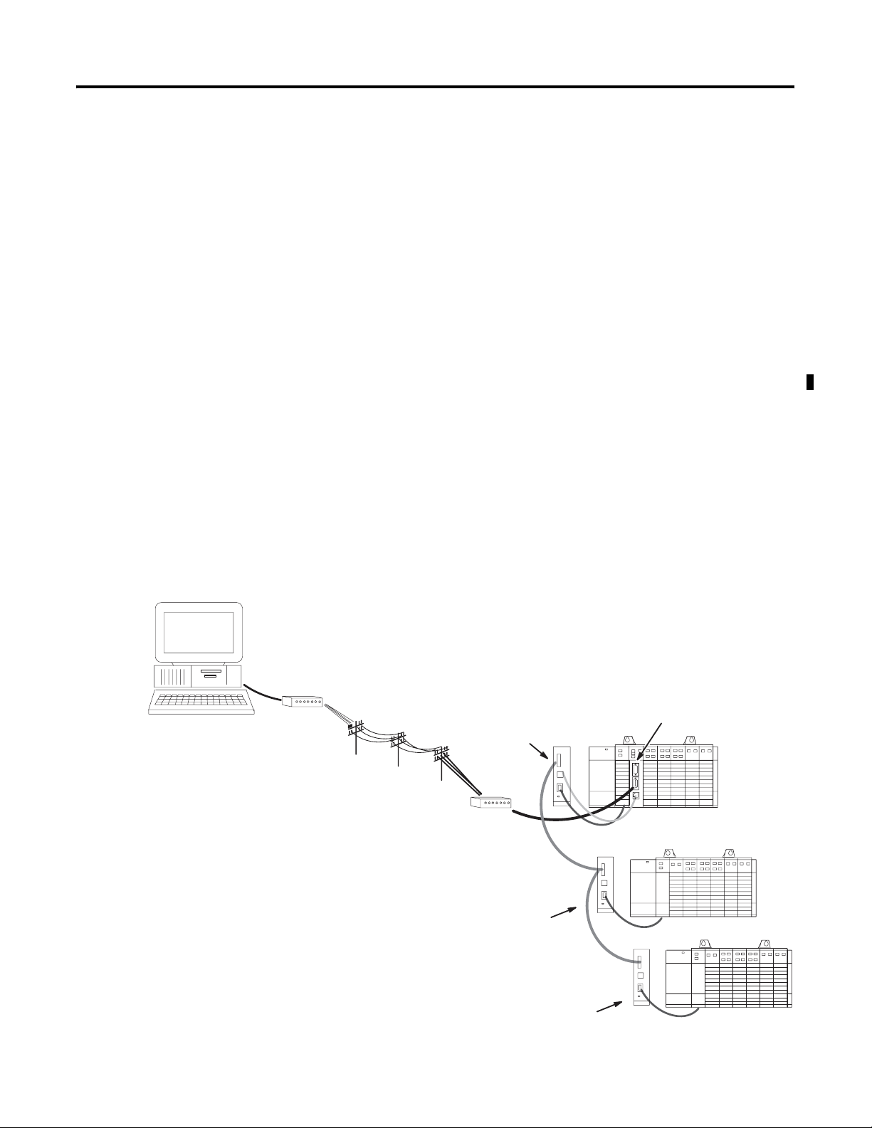
Interface Module Overview
Local Host
Modem
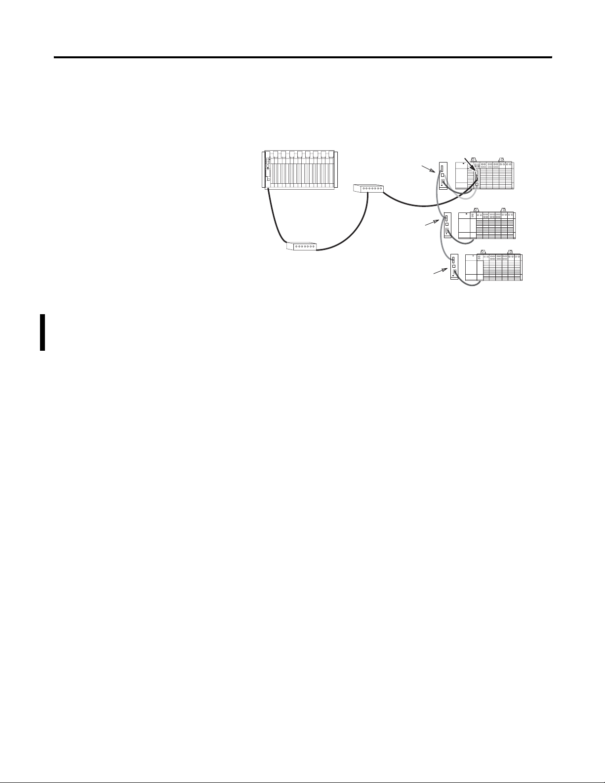
The DH-485/RS-232C Interface Module, catalog number 1747-KE, is a
communications interface module that acts as a bridge between
DH-485 networks and devices requiring DF1 protocol. The DF1 port
on the interface module can be configured for RS-232/423, RS-422, or
RS-485 devices. Residing in an SLC 500 chassis, the module is ideally
used as an interface module, linking remote DH-485 networks via a
modem to a central host.
Interface Module Overview
Interface Module
Link Coupler
(1747-AIC)
Modem
DH-485
(1747-KE)
Link Coupler
(1747-AIC)
DH-485
Link Coupler
(1747-AIC)
1 Publication 1747-UM005B-EN-P - March 2006
Remote Network
Page 14
1-2 Overview
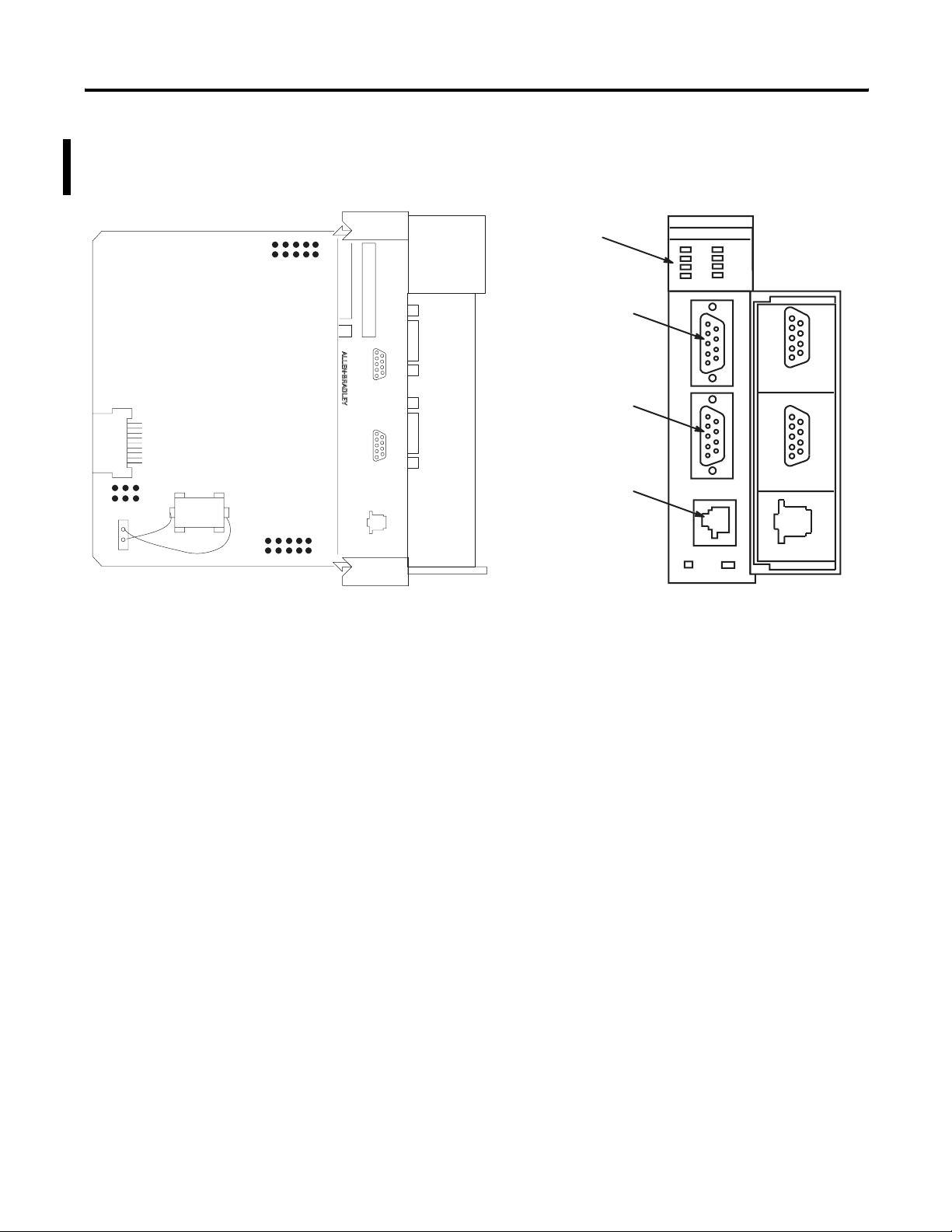
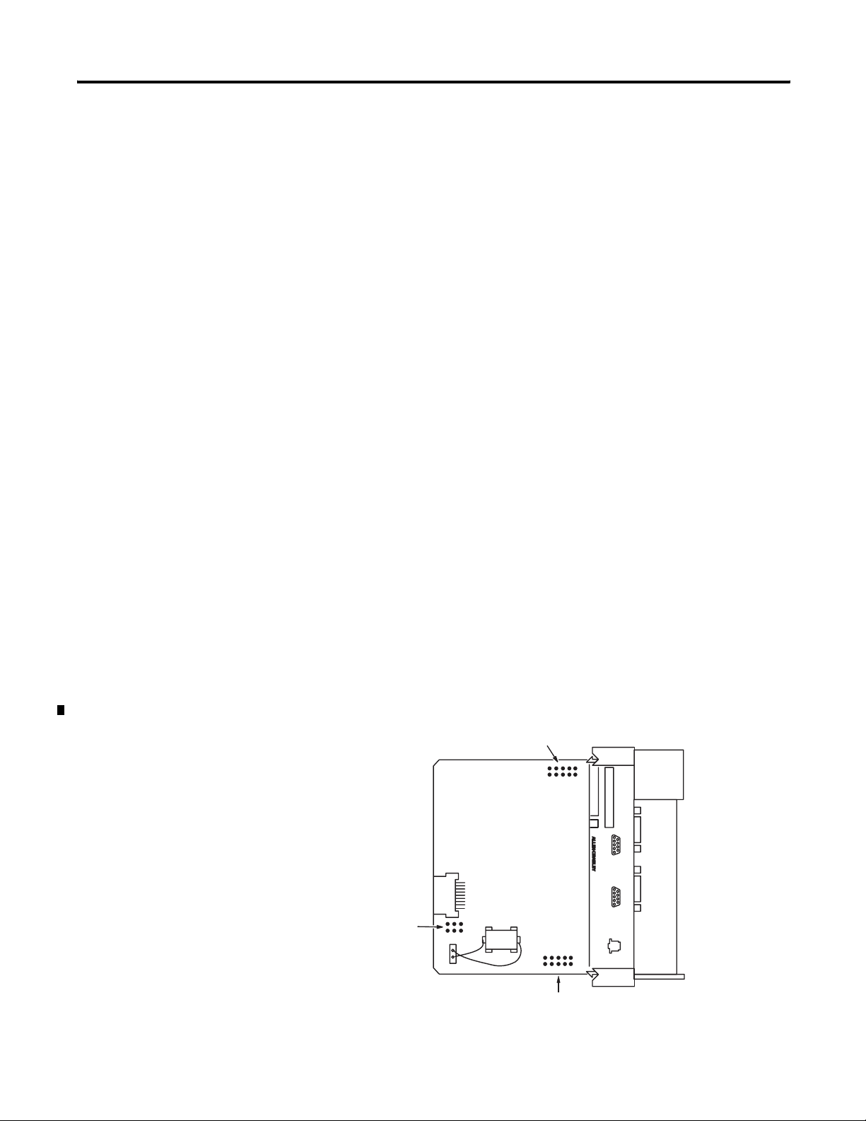
Features
JW4
Battery
JW1
JW2
The features of the module are shown below.
1747-KE Module Features
SERIAL NO.
FRN
CONFIG
12345
DF1
12345
DH485
CAT SER
SLC 500
INTERACE MODULE
6789
6789
LEDs
CONFIG
Port
DF1
Port
DH-485
Port
DH-485/RS-232C
5
4
3
2
1
CONFIG
5
4
3
2
1
DF1
DH485
Door Label
9
8
7
6
9
8
7
6
There are three communication ports on the front of the module.
They are:
• CONFIG - used to configure the module with an ASCII terminal.
This serial port accommodates RS-232/423, RS-422, and RS-485
communication interfaces. The CONFIG port is capable of
operating at 300, 600, 1200, 2400, 4800, 9600, and 19200 Kbps. It
is electrically isolated to 500V dc.
• DF1 - used to interface the module to a modem or other user
devices using DF1 protocol. This serial port accommodates
RS-232/423, RS-422, and RS-485 communication interfaces. The
DF1 port is capable of operating at 300, 600, 1200, 2400, 4800,
9600, and 19200 Kbps. It is electrically isolated to 500V dc.
• DH485 - used to interface the module with the DH-485 network.
This port is not isolated and cannot directly drive a multi-node
DH-485 network. You must use a 1747-AIC link coupler to
connect this port to a DH-485 network that includes multiple
SLC 500 processors.
The 1747-C11 or 1747-C13 cables can connect the interface module’s
DH-485 port to a 1747-AIC link coupler. The 1747-C13 cable can also
connect the module’s DH-485 port directly to a single SLC processor.
Publication 1747-UM005B-EN-P - March 2006
See page 4-11 for cable connections.
Page 15
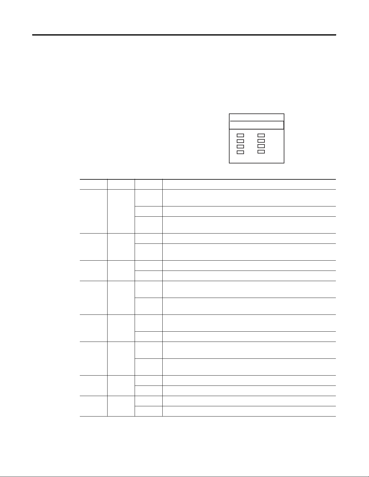
LED Indicators
DH
485/RS-
232
C
There are eight LED indicators on the front of the module. These LED
indicators are used for module diagnostics and operator interface. The
LED indicators and their descriptions are provided below.
LED Indicators
LED Indicator Status
LED Color Status Indication
ACT Green
ON
(1)
The module is receiving power from the backplane, is configured properly, and
is placed in Run mode.
Flashing The module requires configuration or is being configured.
DH
485/RS-
AC
485
C
FG
DF1
INTERFACE
Overview 1-3
232
C
T
FAULT
BA
LO W
H/D
F/
D
OFF The module is not receiving power from the backplane. A fault condition
exists.
485 Green ON The DH485 port is active on the network.
OFF The DH485 port is not active on the network or the module is in Configuration
mode.
CFG Green Flashing The CONFIG port is transmitting or receiving signals.
OFF The CONFIG port is not transmitting or receiving signals.
DF1 Green Flashing The DF1 port is transmitting or receiving signals. (The flashing may occur so
rapidly that the LED indicator appears to be on.)
OFF The DF1 port is not transmitting or receiving signals or the module is in
Configuration mode.
FAULT Red ON A system problem was detected during diagnostics. Cycle power to reset. If it
remains on, contact your Allen-Bradley representative.
OFF No system problems are detected during diagnostics.
BA LOW Red ON The voltage of the battery that backs up configuration RAM is low. A new
battery is needed.
OFF The voltage of the battery that backs up configuration RAM is at an
acceptable level.
H/D Amber ON The module is configured for half-duplex DF1 protocol (local or remote).
OFF The module is not configured for half-duplex DF1 protocol.
F/D Amber ON The module is configured for full-duplex DF1 protocol.
OFF The module is not configured for full-duplex DF1 protocol.
(1)
Indicates normal operation after the module has been configured.
Publication 1747-UM005B-EN-P - March 2006
Page 16
1-4 Overview
Jumper JW1
JW1 lets you to select the communication interface for the CONFIG
port.
Refer to page 4-5.
Jumper JW2
JW2 lets you to select the communication interface for the DF1 port.
Refer to page 4-6.
Jumper JW4
JW4 lets you to select the functionality and mode of the interface
module. The orientation of the jumper determines the module’s
functionality. A horizontal orientation gives the module functionality
equivalent to a series A module (module configuration ID=4209),
while a vertical orientation of the jumper accesses the added
functionality of a series B module (module configuration ID=3509).
The position of the jumper determines the module’s mode
(Configuration or Run), and thus, which method is used to configure
the module (ASCII terminal or backplane communications).
Refer to Chapter 4.
Jumper Placement
JW1
CAT SER
SERIAL NO.
SLC 500
INTERACE MODULE
FRN
CONFIG
6789
12345
DF1
6789
12345
JW4
DH485
Publication 1747-UM005B-EN-P - March 2006
JW2
Page 17
Overview 1-5
Use a Modem with Your Interface Module
The module can be connected to most types of dial-up network or
direct connect modems.
IMPORTANT
The type of modems you can use are:
• Manual - typically acoustically-coupled modems. A person on
each end of the phone line establishes the connection. They
then insert the handsets into an acoustic coupler to complete the
connection.
• DTE controlled answer - these unattended modems are attached
directly to the phone lines. The interface module acts as the
Data Terminal Equipment (DTE), which controls the modem via
the DTR, DSR, and DCD signals. The module incorporates
timeouts and tests to properly operate these types of modems.
• Auto answer - these modems have self-contained timeouts and
tests. They can answer and hang up the phone automatically.
The module has no means of controlling an auto-dial modem,
but it can be used in conjunction with a separate auto-dialer.
• Direct connect - these modems connect to a dedicated, leased
phone line and remain active at all times.
Some modems are designed to respond to the DTR
signal by answering the phone whether it is ringing
or not. Since the module asserts DTR at all times
(except during the hang-up sequence), the phone
appears to be busy at all times. Do not use the
interface module with any type of modem that
answers the phone as soon as DTR is asserted.
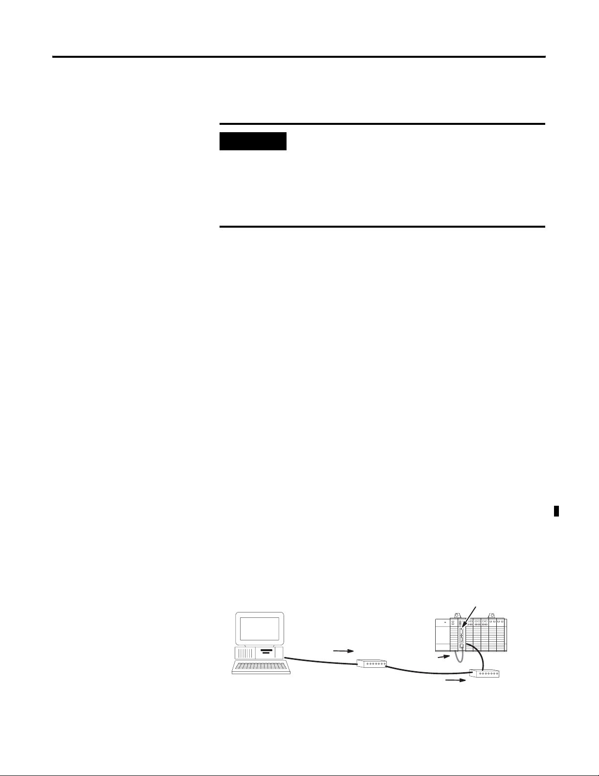
Use DF1 Protocol and Your Module
RSLinx software supports DF1 communications directly from your
computer’s serial communication port. Connecting a modem to this
port lets you to call remote networks and control them as if you were
connected locally.
DF1 Protocol
Interface Module
(1747-KE)
DF1
DF1 Protocol
1747-C13 Cable
Modem
DF1 Protocol
Publication 1747-UM005B-EN-P - March 2006
Modem
Page 18
1-6 Overview
Typical Configurations
The following configurations illustrate some of the possible uses for
the module.
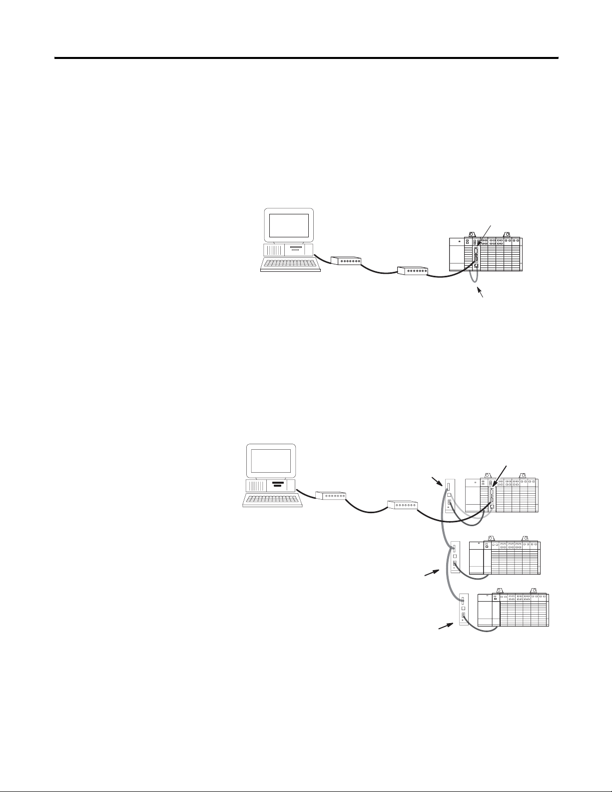
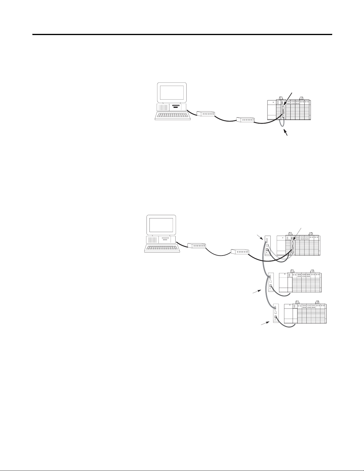
Full-duplex (Point-to-point)
Full-duplex (Point-to-point)
Interface Module
DF1
Modem
Modem
This illustration shows a connection to a single remote SLC node. The
1747-C13 cable eliminates the need for a 1747-AIC link coupler.
(1747-KE)
1747-C13 Cable
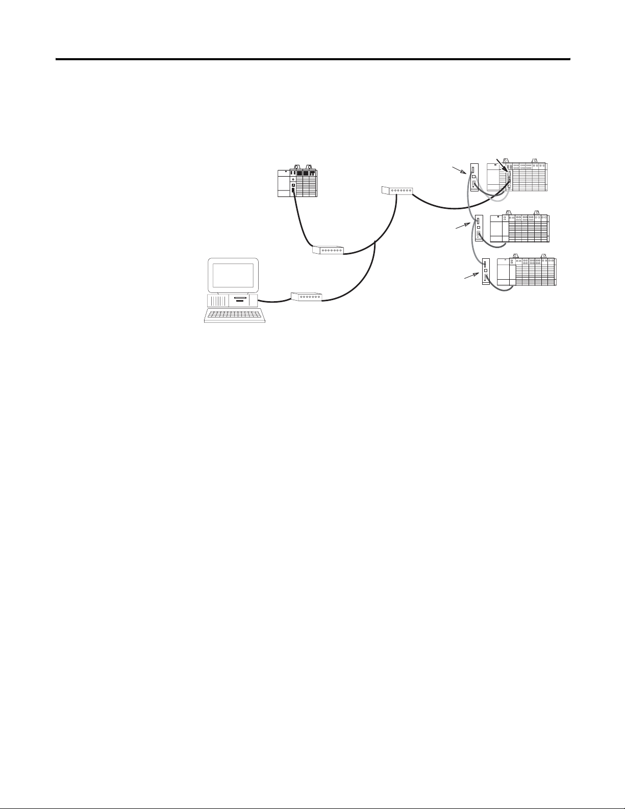
Full-duplex (Network, Example 1)
Full-duplex (Network, Example 1)
Interface Module
RSLInx
Link Coupler
(1747-AIC)
Modem
Modem
Link Coupler
(1747-AIC)
Link Coupler
(1747-AIC)
This illustration shows a connection to a remote DH-485 network of
up to 31 SLC nodes.
(1747-KE)
Publication 1747-UM005B-EN-P - March 2006
Page 19
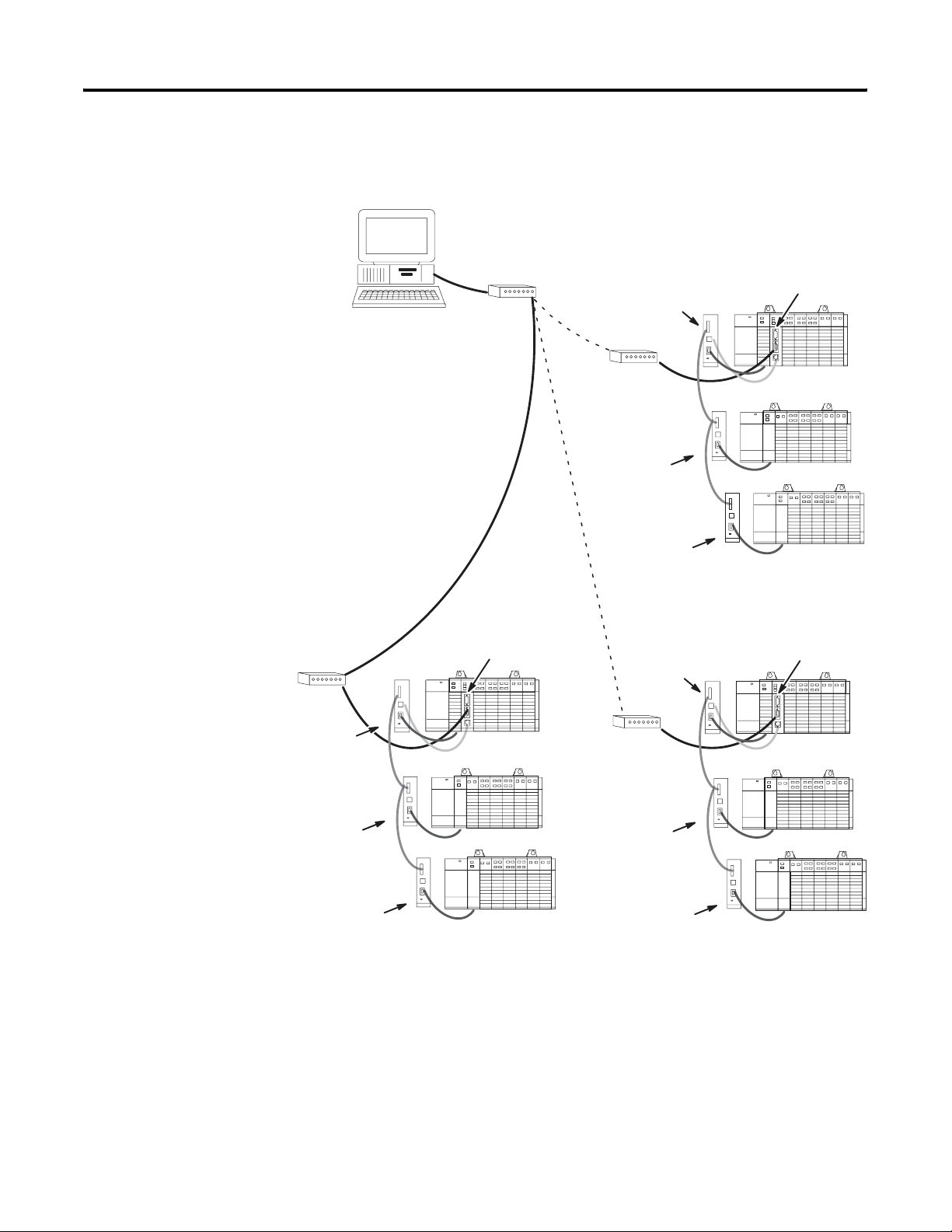
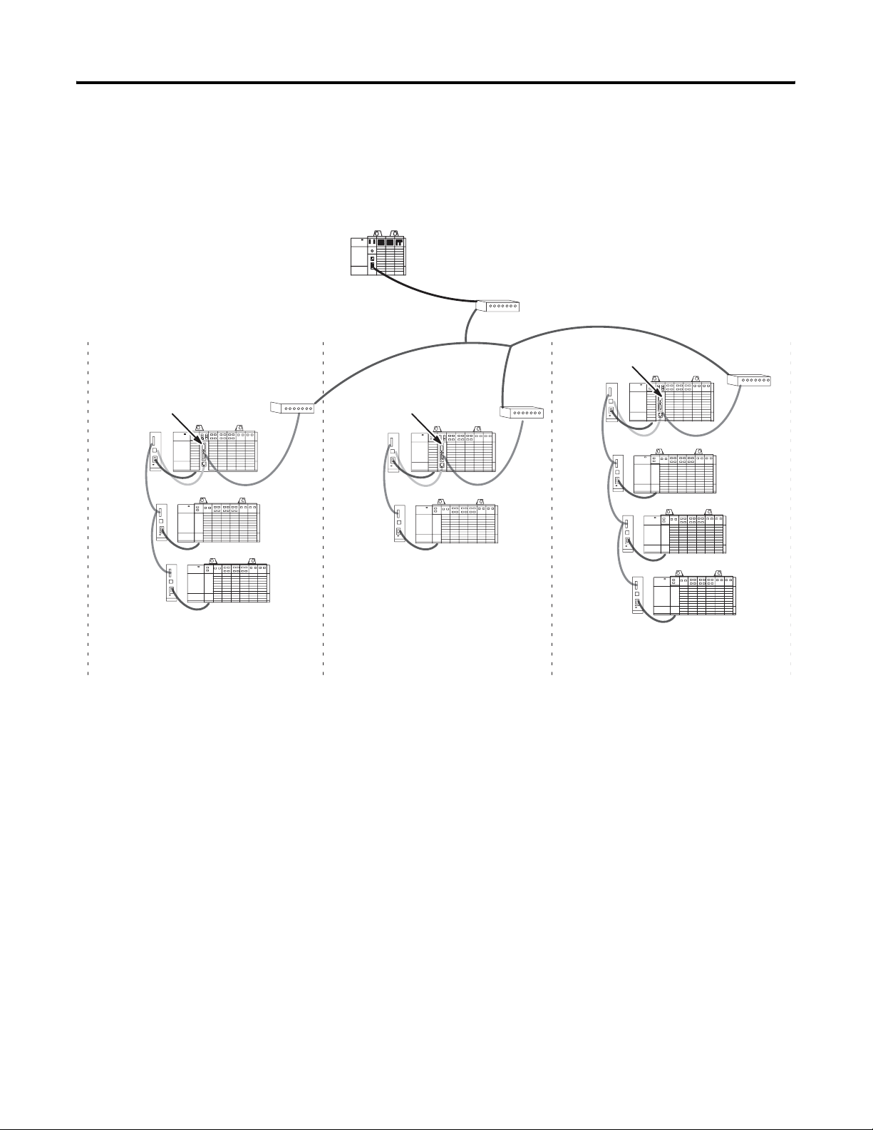
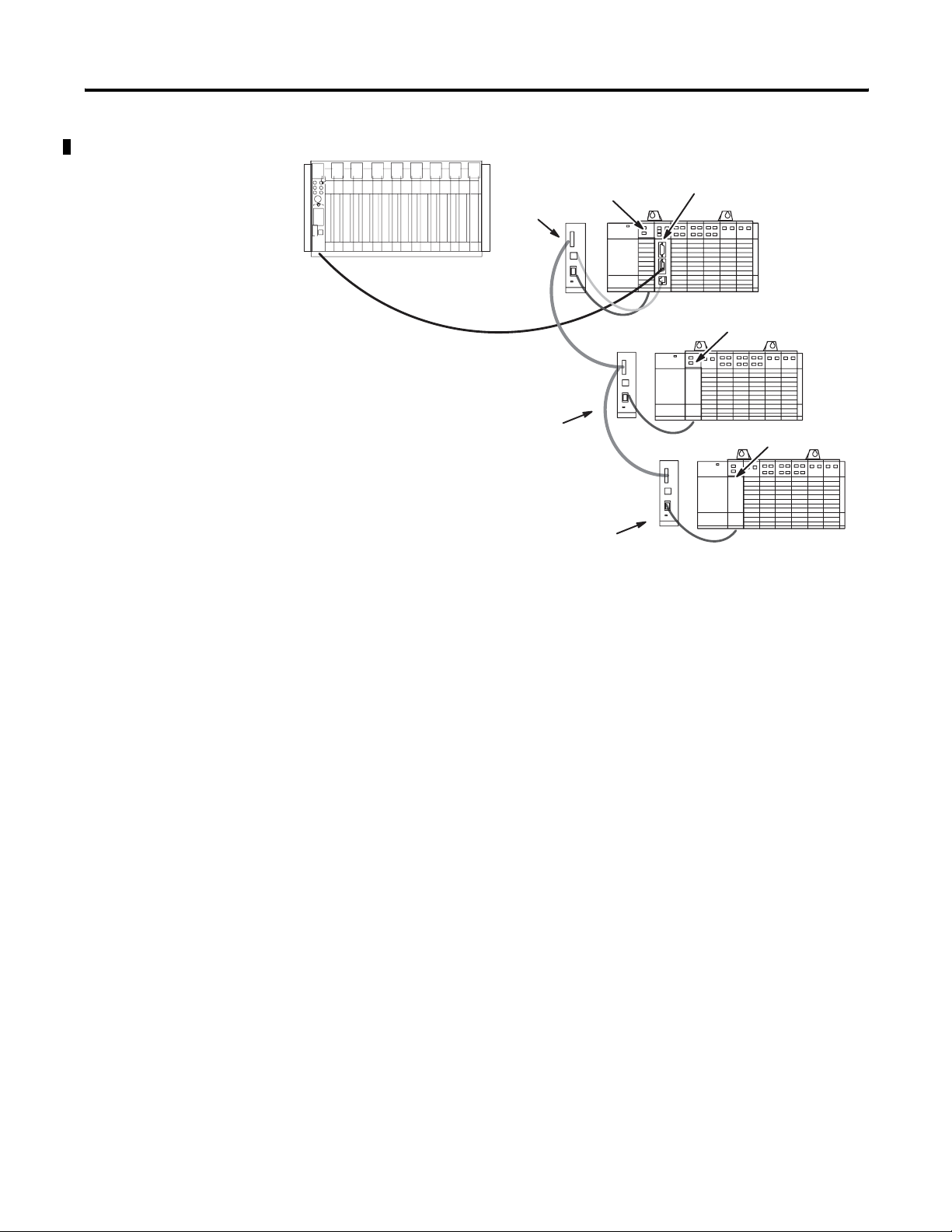
Full-duplex (Network, Example 2)
Full-duplex (Network, Example 2)
RSLinx
Modem
Host computer is capable of
calling and interfacing with
one network at a time.
Overview 1-7
Interface Module
(1747-KE)
Link Coupler
(1747-AIC)
Modem
Link Coupler
(1747-AIC)
Modem
Link Coupler
(1747-AIC)
Link Coupler
(1747-AIC)
Link Coupler
(1747-AIC)
Link Coupler
(1747-AIC)
Interface Module
(1747-KE)
Link Coupler
(1747-AIC)
Modem
Link Coupler
(1747-AIC)
Link Coupler
(1747-AIC)
Interface Module
(1747-KE)
This configuration allows the host to call more than one remote
network (one network connected at a time). Each remote network can
consist of up to 31 SLC nodes.
Publication 1747-UM005B-EN-P - March 2006
Page 20
1-8 Overview
Half-duplex (Local Mode)
Half-duplex (Local Mode) Master
Interface Module
PLC-5
processor
Modem
Link Coupler
(1747-AIC)
Modem
Link Coupler
(1747-AIC)
Link Coupler
(1747-AIC)
This configuration allows the host controller to interface on a remote
DH-485 network of up to 31 SLC nodes using the half-duplex
protocol.
(1747-KE)
Publication 1747-UM005B-EN-P - March 2006
Page 21
Half-duplex (Remote Mode)
Half-duplex (Remote Mode) Master
SLC 5/05
processor
Overview 1-9
Dedicated Line
Modem
Interface Module
(1747-KE)
Dedicated Line
Modem
Dedicated
Line Modem
Interface Module
(1747-KE)
Group 01Group 00
Dedicated Line
Modem
Interface Module
(1747-KE)
Group
02
This illustration shows a host connect up to eight groups of DH-485
networks, connecting up to a total of 254 SLC nodes.
Publication 1747-UM005B-EN-P - March 2006
Page 22
1-10 Overview
Half-duplex (Slave-to-slave Communication)
Half-duplex (Slave-to-slave Communication)
Link Coupler
Link Coupler
(1747-AIC)
SLC 5/05
processor
Dedicated Line
Modem
(1747-AIC)
Interface Module
(1747-KE)
(DF1 Slave)
RSLinx
(DF1 Slave)
Dedicated Line
Modem
Dedicated Line
Modem
Link Coupler
(1747-AIC)
Link Coupler
(1747-AIC)
This configuration allows a DF1 slave device send a message to
another DF1 slave device. In this example, RSLinx can communicate
to an SLC slave.
Publication 1747-UM005B-EN-P - March 2006
Page 23

Chapter
2
Quick Start
This chapter can help you to get started using the DH-485/RS-232C
Interface Module (catalog number 1747-KE). The procedures included
here assume that you have a basic understanding of SLC 500 products.
You should understand electronic process control and be able to
interpret the ladder logic instructions required to generate the
electronic signals that control your application.
Because it is a start-up guide, this chapter does not contain detailed
explanations about the procedures listed. It does, however, reference
other chapters in this book where you can get more information about
applying the procedures described in each step.
Required Tools and Equipment
If you have any questions or are unfamiliar with the terms used or
concepts presented in the procedural steps, always read the
referenced chapters and other recommended documentation before
trying to apply the information.
This chapter:
• tells you what tools and equipment you need.
• lists preliminary considerations.
• explains how to install the module.
• describes when to configure the module.
• discusses system start-up procedures.
Have the following tools and equipment ready.
• Medium blade screwdriver
• Programming equipment (RSLogix 500 software)
1 Publication 1747-UM005B-EN-P - March 2006
Page 24
2-2 Quick Start
Procedures
Unpack the Module
Remove the items from the package making sure that the contents
include:
• DH-485/RS-232C Interface Module (catalog number 1747-KE).
• cable (1747-C13).
• installation instructions, publication 1747-IN006.
If the contents are incomplete, call your local Rockwell Automation
representative for assistance.
Install the Module
ATTENTION
Do not install or remove the 1747-KE module from
the SLC chassis until all power dissipates from the
SLC 500 power supply (approximately 10 seconds).
Install the module and configure the SLC chassis. The following steps
summarize these procedures.
1. Choose the module’s functionality.
2. Select the configuration method you want to use and place your
module in the corresponding mode using JW4.
3. Set your CONFIG and DF1 ports using JW1 and JW2.
4. Configure your SLC chassis using RSLogix 500 software.
5. Configure the module.
6. If your module is still in Configuration mode, place it in Run
mode using the JW4 jumper.
7. Connect your DH-485 and DF1 cabling.
8. Turn on power and verify module status.
For more information refer to Chapter 4 (Installation and System
Configuration).
Publication 1747-UM005B-EN-P - March 2006
Page 25

Quick Start 2-3
Configure the Module
Configure the module by either connecting to an ASCII terminal or
communicating through the backplane.
For more information, see Chapter 5 (Module Configuration Using an
ASCII Terminal) and Chapter 6 (Module Configuration Using the
Backplane).
Start-up the Module
Power up your system by performing standard start-up procedures as
indicated in your processor manual. No special start-up procedures
are required when using the module.
Before applying power to the module, make sure:
• the module is installed in the SLC chassis.
• all communication devices are connected.
• your SLC processor is configured to operate with the interface
module.
Refer to Chapter 4 for more information.
• your interface module is configured properly.
Refer to Chapters 5 and 6 for more information.
When power is applied to the SLC system, the SLC processor and
module run through a power cycle diagnostic sequence. After the
diagnostics are successfully completed, the SLC processor enters Run
mode and normal operation begins.
ATTENTION
This module is a device used for communications.
Improper configuration or module failure may cause
communications to stop. Be careful to avoid system
designs that would cause potential safety concerns
within the system in the event of a communications
failure.
Publication 1747-UM005B-EN-P - March 2006
Page 26

2-4 Quick Start
Publication 1747-UM005B-EN-P - March 2006
Page 27

Chapter
Communicate with the Interface Module
This chapter explains:
• full- and half-duplex DF1 communication.
• local and remote half-duplex operation.
• communicating with master and slave DH-485 devices.
• communicating with a modem.
3
DF1 Communication
The module supports full-duplex DF1 protocol and half-duplex DF1
slave protocol on its RS-232 connection to the host computer (using
the DF1 Port). The details of these protocols can be found in the DF1
Protocol and Command Set Reference Manual, publication
1770-RM516.
Full-duplex DF1 Protocol
Full-duplex DF1 protocol is provided for applications where high
performance peer-to-peer communication is needed.
In full-duplex mode, the module can send embedded responses. If the
embedded response detect option is set to auto-detect embedded
response, the module will not send embedded responses until it
receives one from the host. The module makes an assumption that if a
host computer sends embedded responses, it can also receive them.
In full-duplex mode, the destination address in a packet sent from the
host computer to the module is the address of the DH-485 node for
which the packet is intended. The source address in packets received
by the host computer from the module is the node address of the
sender.
1 Publication 1747-UM005B-EN-P - March 2006
Page 28
3-2 Communicate with the Interface Module
Full-duplex (Point-to-point)
Full-duplex (Point-to-point)
Interface Module
RSLinx
Modem
Modem
(1747-KE)
1747-C13 Cable
This illustration shows a connection to a single remote SLC node. The
1747-C13 cable eliminates the need for a 1747-AIC link coupler for
connections to one node.
Full-duplex (Network Example)
Full-duplex (Network Example)
Interface Module
RSLinx
Link Coupler
((1747-AIC)
Modem
Modem
Link Coupler
((1747-AIC)
Link Coupler
((1747-AIC)
(1747-KE)
This illustration shows a connection to a remote DH-485 network of
up to 31 SLC nodes.
Publication 1747-UM005B-EN-P - March 2006
Half-duplex DF1 Protocol
The module provides two modes of half-duplex addressing: local and
remote. Local mode is provided for compatibility with earlier DF1
products, such as the Data Highway/Data Highway Plus
Asynchronous Interface Module (catalog number 1770-KF2) and when
only one interface module is used in the system.
Page 29

Communicate with the Interface Module 3-3
You may prefer local mode for use in applications where the RS-232C
link is not networked, since it simplifies the polling algorithm.
Remote mode should be used when more than 31 SLC nodes are
required on the DH-485 network. Because the interface module is
transparent to the master device, existing drivers can be used without
rewriting.
Local Mode
Local mode requires an intelligent master device, capable of
specifying both a station address and a destination address. Because
the interface module acts as a slave on a half-duplex network, the
half-duplex master’s access to the DH-485 node is indirect. The
destination address and the station address are generally different.
In local mode, the polling algorithm used by the half-duplex master is
simplified so that the master only needs to poll the single interface
module. The module will respond to messages from the half-duplex
master only if the station address contained in these messages is the
node address of the interface module. The module then forwards the
packet to the appropriate DH-485 node, as defined by the destination
address.
Responses from remote nodes on the DH-485 network contain a
destination address equal to that of the interface module, and not that
of the half-duplex master device. The module responds to poll
packets from the half-duplex master by returning whatever data has
been forwarded to it by the remote nodes under its jurisdiction.
In the Local Mode illustration on page 3-4, the half-duplex master only
polls the interface module at station address 01.
Messages from the half-duplex master to the SLC 500 controllers are
sent using a master message containing both the station address of the
interface module (node 01) and the destination address of the SLC 500
controller (node 03 for example). Responses from the SLC 500
controllers to the half-duplex master contain the destination address
of the interface module (node 01), which then returns all responses to
the half-duplex master station upon being polled.
During configuration of the interface module, the module’s
destination address, or slave address, is selected if Local mode has
been selected.
Publication 1747-UM005B-EN-P - March 2006
Page 30
3-4 Communicate with the Interface Module
Local Mode
PLC 5
controller
DF1 Master
Remote Mode
Link Coupler
((1747-AIC)
RS-232C DF1
Link Coupler
((1747-AIC)
DH-485
SLC 500
Node 02
DH-485
Link Coupler
((1747-AIC)
SLC 500
Node 01
SLC 500
Node 03
SLC 500
Node 00
The valid range of slave addresses on a half-duplex network is 000
through 376 octal (000 through 254 decimal) accommodating a total of
255 devices. The valid range of addresses on a DH-485 network is 00
through 37 octal (00 through 31 decimal).
To let addressing of up to 255 DH-485 nodes, eight groups (group
numbers 00 through 07) of DH-485 networks are established. Each
group number defines a DH-485 network, which can consist of up to
32 nodes each (except for group 07 which is limited to 31 nodes).
Refer to the table on page 3-6.
During configuration of the interface module, the module’s group
number is selected if Remote mode has been selected.
In remote mode, the module appears transparent to the half-duplex
master, so that remote SLC 500 controllers can be polled directly as
individual slaves on the half-duplex network. The interface module
responds to the half-duplex master if the station address specified
corresponds to the node address of any (token-passing) station on
the DH-485 network connected to that interface module.
Publication 1747-UM005B-EN-P - March 2006
Page 31

Communicate with the Interface Module 3-5
Messages from the remote nodes on the DH-485 network (such as the
SLC nodes) use the destination address of the module. Normally the
module responds to a message from the DF1 master by swapping the
source and destination addresses in the received message, assuring
that the reply message is sent to the proper DF1 master station.
If a DH-485 node initiates a message to the DF1 master, the module
overwrites the destination address with the master station value
configured in the Remote mode submenu. The message received by
the half-duplex master will contain a source address equal to the
station address specified in the poll packet, and a destination address
equal to the address of the half-duplex master device.
Remember that half-duplex DF1 (group) addresses are in octal and
DH-485 node addresses are in decimal.
The table on page 3-6 provides the conversion using the group
number.
Publication 1747-UM005B-EN-P - March 2006
Page 32

3-6 Communicate with the Interface Module
Half-duplex Remote Address Conversion Table
DH-485
Node
Address
(decimal)
Group 00 Group 01 Group 02 Group 03 Group 04 Group 05 Group 06 Group 07
Half–duplex DF1 Address (octal)
00 000 040 100 140 200 240 300 340
01 001 041 101 141 201 241 301 341
02 002 042 102 142 202 242 302 342
03 003 043 103 143 203 243 303 343
04 004 044 104 144 204 244 304 344
05 005 045 105 145 205 245 305 345
06 006 046 106 146 206 246 306 346
07 007 047 107 147 207 247 307 347
08 010 050 110 150 210 250 310 350
09 011 051 111 151 211 251 311 351
10 012 052 112 152 222 252 322 352
11 013 053 113 153 213 253 313 353
12 014 054 114 154 214 254 314 354
13 015 055 115 155 215 255 315 355
14 016 056 116 156 216 256 316 356
15 017 057 117 157 217 257 317 357
16 020 060 120 160 220 260 320 360
17 021 061 121 161 221 261 321 361
18 022 062 122 162 222 262 322 362
19 023 063 123 163 223 263 323 363
20 024 064 124 164 224 264 324 364
21 025 065 125 165 225 265 325 365
22 026 066 126 166 226 266 326 366
23 027 067 127 167 227 267 327 367
24 030 070 130 170 230 270 330 370
25 031 071 131 171 231 271 331 371
26 032 072 132 172 232 272 332 372
27 033 073 133 173 233 273 333 373
28 034 074 134 174 234 274 334 374
29 035 075 135 175 235 275 335 375
30 036 076 136 176 236 276 336 376
31 037 077 137 177 237 277 337 Illegal
Publication 1747-UM005B-EN-P - March 2006
Page 33

Remote Mode Addressing on a Multi-drop Network Example
This example shows a PLC-5 controller as the half-duplex master in a
multi-drop configuration. Each interface module has been configured
after Remote mode has been selected. The half-duplex master address
of the PLC-5 controller has been set to 010 (octal).
Remote Mode Addressing on a Multi-drop Network
PLC-5 processor
010
8
Communicate with the Interface Module 3-7
Dedicated Line
Modem
SLC 500
005
8
05
SLC 500
002
02
SLC 500
011
09
Interface Module
010
8
01
8
8
Dedicated Line
Modem
Interface Module
040
8
Dedicated Line
Modem
00
SLC 500
044
8
04
SLC 500
043
8
03
XXX
= DF1 Multi-drop Address (octal)
8
XX = DH-485 Local (decimal) Network Address
Group 01Group 00
SLC 500
100
8
00
SLC 500
131
8
25
SLC 500
120
16
Interface Module
0101
8
01
8
SLC 500
104
8
04
Group
Dedicated Line
Modem
02
IMPORTANT
Each interface module must be set up for a unique
group number.
Publication 1747-UM005B-EN-P - March 2006
Page 34

3-8 Communicate with the Interface Module
The group number is used by the interface module to create a
half-duplex DF1 address for each node on the DH-485 network. The
DF1 addresses are the octal equivalent of an eight bit binary word
with the three most significant bits corresponding to the group
number and the five least significant bits corresponding to the local
network address.
Addresses
Group Number
(3 in this example)
and
DH-485 Local Network Address
(29 in this example)
011 11101
combine to make
this binary word
which has this octal value.
(DF1 Multi-drop Address)
The following table lists the devices from the above network along
with their DH-485 local network address and their DF1 multi-drop
address.
Devices and Corresponding Addresses
Group Device DH-485 Address
00 1747–KE 01 00|000|001 001
SLC 500 02 00|000|010 002
SLC 500 05 00|000|101 005
SLC 500 09 00|001|001 011
01 1747–KE 00 00|100|000 040
SLC 500 04 00|100|100 044
SLC 500 03 00|100|011 043
1747–KE 01 01|000|001 101
02 SLC 500 00 01|000|000 100
SLC 500 25 01|011|001 131
SLC 500 16 01|010|000 120
SLC 500 04 01|000|100 104
01
(decimal)
111 101
17
DF1 Address
(binary)
5
DF1 Address
(octal equivalent)
Publication 1747-UM005B-EN-P - March 2006
Page 35

Communicate with the Interface Module 3-9
Slave-to-slave Communication
The interface module lets communication from a DH-485 network
device to a single DF1 slave device, regardless of which mode of
half-duplex addressing is selected (local or remote). To achieve this,
the interface module’s Master Station Address must be configured as
that DF1 slave address.
For example, if the RSLinx terminal in the illustration below is DF1
node 3, the interface module’s Master Station Address must be
configured as node 3.
Slave-to-slave Communication
PLC-5
processor
(DF1 Master)
(DF1 Slave)
DF1 Slave
Dedicated Line
Modem
Dedicated Line
Modem
Dedicated Line
Modem
Link Coupler
(1747-AIC)
Link Coupler
(1747-AIC)
Link Coupler
(1747-AIC)
Interface Module
(1747-KE)
In this illustration, a packet from the RSLinx computer, intended for an
SLC node, is first transferred to the PLC-5 controller (DF1 master). The
PLC-5 controller then transfers the packet to the interface module,
which converts it to a DH-485 packet and sends it to the specified SLC
node. The SLC node’s response goes through the interface module to
the PLC-5 controller. The PLC-5 controller then transfers the response
to the RSLinx computer.
The operation of slave-to-slave communication differs slightly
depending on whether the interface module is in local or remote
mode.
Publication 1747-UM005B-EN-P - March 2006
Page 36

3-10 Communicate with the Interface Module
Slave-to-slave communication
When the interface module is in Slave-to-slave communication occurs
Local mode Only if the module’s DF1 node is the same as the
DH-485 node for which the message is destined.
In this mode the RSLinx computer can only
communicate with one SLC node.
For example, if you want a DF1 slave terminal in
the illustration above to communicate with an
SLC processor in node 2 of the DH-485 network,
then the interface module’s DF1 slave address
must be set to 2.
Remote mode Between the DF1 slave and any of the DH-485
devices connected to the interface module. The
addresses for the DH-485 devices are
determined by the group number in the interface
module.
Refer to the Half-duplex Remote Address
Conversion Table in Chapter 3.
Communicate with DH-485 Devices
For example, if the interface module in the
illustration above is configured as group 03, and
the DH-485 node to be accessed has a DH-485
address of 01, then the DF1 slave device will use
address 141 (octal) when accessing this device.
ATTENTION
Do not force outputs to a remote SLC system through
the interface module. Phone line disturbances,
interface module failure, or other system failure
could disrupt remote communications and cause the
outputs to remain active.
DH-485 Token Passing Devices
The interface module operates as a token passing master on the
DH-485 network. It can communicate with other DH-485 master
stations (such as an SLC 5/02 processor) and with DH-485 token
passing slave devices (such as an SLC 5/01 processor).
Publication 1747-UM005B-EN-P - March 2006
The module communicates with other master stations using the
Allen-Bradley programmable controller command set. For details,
refer to the DF1 Protocol and Command Set Reference Manual,
publication 1770-RM516.
Page 37

Communicate with the Interface Module 3-11
DH-485 Non-Token Passing Devices
The DH-485 network also supports non-token passing slave devices.
The module communicates with these slaves using a special PLC
command (CMD) byte.
Application programs communicate with non-token passing slaves via
Send and Receive Data (SRD) messages on DH-485. The SRD message
is a link layer service provided on DH-485. The Programmable
Controller Communications Command Set (PCCC) has been extended
to provide SRD messages by setting the PCCC CMD byte to 09. The
SRD message cannot be used in slave-to-slave communication.
A detailed description of the packet is found in the DF1 Protocol and
Command Set Reference Manual, publication 1770-RM516.
The format of the application layer data within the packet is
completely dependent on how the destination device is implemented.
Refer to the destination device’s user manual for this information.
Communicate with a Modem
The hardware handshaking option must be enabled for the module to
properly control a modem.
The module continually asserts DTR while it is waiting for a call.
Under this condition, the modem answers a call and asserts DCD
upon connection. When the module detects DCD, communications
can start.
After detecting DCD, the module continues to monitor the DCD line.
If DCD goes off, the module restarts the 10-second timeout. If DCD is
not restored within 10 seconds, the module initiates the hang-up
sequence. This feature lets the remote node to redial in case the
connection was lost due to a fault in the phone system.
This handshaking is necessary to guarantee access to the phone line.
If the handshaking protocol is defeated by improper selection of
modem options or wiring of communication cables, the modem may
still answer a call. But if the connection is lost, the modem will not
hang up. It will then be impossible for the remote node to reestablish
the connection because it will get a busy signal.
Publication 1747-UM005B-EN-P - March 2006
Page 38

3-12 Communicate with the Interface Module
For successful modem communication be sure that:
• RSLinx software and the interface module agree on
communication rate and error checking.
• both modems have the echo disabled.
• both modems have Carrier Detect set to normal (unforced).
• both modems have DTR Dialing disabled.
• the modem to receive the call has auto answer enabled.
Publication 1747-UM005B-EN-P - March 2006
Page 39

Chapter
Installation and System Configuration
This chapter provides the following installation and system
configuration information.
• European Union directives compliance
• Module functionality
• Mode selection
• Port configuration verification
• Module installation
• Cable connection
•
SLC chassis, DF1 driver, and module configuration
4
European Union Directives Compliance
ATTENTION
If this product has the CE mark, it is approved for installation within
the European Union and EEA regions. It has been designed and tested
to meet the following directives.
Do not install or remove the 1747-KE module from
the SLC chassis until all power dissipates from the
SLC 500 power supply (approximately 10 seconds).
EMC Directive
This product is tested to meet Council Directive 89/336/EEC
Electromagnetic Compatibility (EMC) and the following standards, in
whole or in part, documented in a technical construction file:
• EN 50081-2
EMC - Generic Emission Standard, Part 2 - Industrial
Environment
• EN 50082-2
EMC - Generic Immunity Standard, Part 2 - Industrial
Environment
This product is intended for use in an industrial environment.
1 Publication 1747-UM005B-EN-P - March 2006
Page 40

4-2 Installation and System Configuration
Choose the Module’s Functionality
Your series B interface module has the ability to function as a series A
interface module. This feature may be important to you if you are
replacing a series A module with a series B module.
Refer to page 4-2 for more information.
The module’s functionality depends on the placement of the JW4
jumper. Horizontal placement of the jumper gives the module
functionality equivalent to a series A interface module, while vertical
placement of the jumper accesses the added functionality of a series B
interface module.
Module Functionality Settings
Series A Functionality
(mod. config. ID=4209)
Horizontal
Configuration
Mode
Horizontal Run
Mode
Series B Functionality
(mod. config. ID=3509)
Vertical
Configuration
Mode
Vertical Run
Mode
Add an Interface Module to Your System
If you are not replacing a series A module, you will want to access the
full functionality of the series B module. Therefore, as you work
through the remainder of this manual, follow the instructions for
series B functionality (vertical placement of the JW4 jumper).
Skip the next section and move on to Set the Module’s Mode.
Replace a Series A Interface Module in Your System
IMPORTANT
Series A Functionality
If you do not want to alter the existing configuration in your user
program in any way, choose the series A functionality for your new
module. The horizontal placement of JW4 gives the series B module a
Choosing series B functionality requires you to
change the module configuration ID assigned in
your processor.
Publication 1747-UM005B-EN-P - March 2006
Page 41

Installation and System Configuration 4-3
module configuration ID equivalent to the module configuration ID of
the series A module you are replacing (4209).
As you work through the remainder of this manual, follow the
instructions for series A functionality (horizontal placement of the JW4
jumper).
IMPORTANT
The increased functionality of the series B interface
module (for example, the Real Time Clock,
backplane configuration, and SLC processor reset of
the interface module) is not available with the series
A functionality.
Series B Functionality
The series B module functions identical to the series A module, but
has these additional features.
• Real Time Clock (RTC)
• Backplane configuration
• SLC processor reset of the interface module
If you want to use the added features of the series B interface module,
follow the directions given for series B functionality (vertical
placement of the JW4 jumper) as you work through the remainder of
this manual.
IMPORTANT
You will be required to change the module
configuration ID assigned in your processor. The
vertical placement of the JW4 jumper gives your
module a configuration ID that differs from the
configuration ID of your series A interface module.
The procedure for changing the module
configuration ID is explained later in this chapter.
See page 4-13 for more information.
Publication 1747-UM005B-EN-P - March 2006
Page 42

4-4 Installation and System Configuration
Set the Module’s Mode
Setting the module’s mode depends on which method you want to
use to configure the module. You can configure the module using:
• an ASCII terminal.
• backplane communications.
IMPORTANT
You can only use backplane communications if you
selected series B functionality for the module.
Decide which method you want to use and then place the JW4 jumper
according to the directions given below.
Configure with an ASCII Terminal
Configuration of the interface module with an ASCII terminal is
allowed only when the JW4 jumper is in Configuration mode. Place
the module in the Configuration mode that corresponds to the
functionality you chose for the interface module.
JW4 in Configuration Mode
Series A Functionality Series B Functionality
Horizontal
Configuration
Mode
Vertical
Configuration
Mode
Configure Through the Backplane
Reading and writing configuration data through the backplane is
allowed only for series B interface modules, and then only when the
JW4 jumper is in the vertical Run mode position. Place the module in
vertical Run mode.
JW4 in Vertical Run Mode
JW4
Publication 1747-UM005B-EN-P - March 2006
Vertical Run Mode
Page 43

Installation and System Configuration 4-5
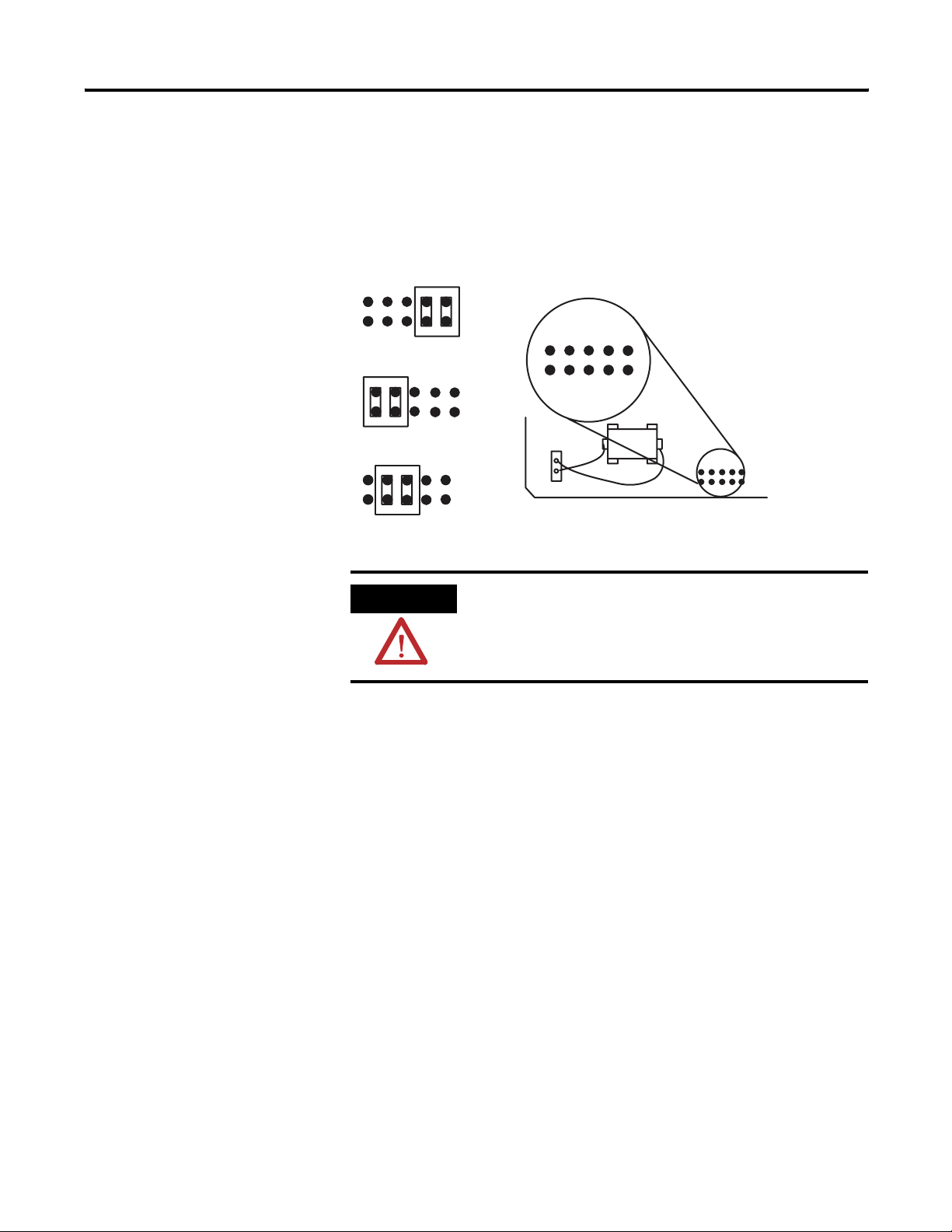
Verify CONFIG Port Configuration
RS-423/232
RS-422
RS-485
Jumper JW1, located at the top of the module, selects the following
electrical interface for the CONFIG port.
• RS-423/232 (default)
• RS-422
• RS-485
CONFIG Port Configuration
246810
13579
JW1 CONFIG Port
ATTENTION
All other jumper settings are illegal and may cause
damage to the module.
Publication 1747-UM005B-EN-P - March 2006
Page 44
4-6 Installation and System Configuration
Verify DF1 Port Configuration
RS-423/232
RS-485
RS-422
Jumper JW2 selects the following electrical interface for the DF1 port.
• RS-423/232 (default)
• RS-422
• RS-485
DF1 Port Configuration
13579
246810
JW2 DF1 Port
ATTENTION
All other jumper settings are illegal and may cause
damage to the module.
Publication 1747-UM005B-EN-P - March 2006
Page 45

Installation and System Configuration 4-7
Install Your Module in an Open Slot
Installation procedures for this module are the same as any other
digital I/O or specialty module.
IMPORTANT
ATTENTION
Make sure you have JW1, JW2, and JW4 configured.
Do not install or remove the 1747-KE module from
the SLC 500 chassis until all power dissipates from
the SLC 500 power supply (approximately 10
seconds).
To install the module:
1. Align the full-size module circuit board with the chassis card
guide.
The first slot (slot 0) of the first chassis is reserved for the CPU.
2. Slide the module into the chassis until the top and bottom
latches are latched.
To remove the module, press the releases at the top and bottom
of the module and slide it out.
Module Release
Card Guide
Publication 1747-UM005B-EN-P - March 2006
Page 46

4-8 Installation and System Configuration
Connect Cable to CONFIG or DF1 Ports
The CONFIG and DF1 ports communicate to user devices through
RS-423/232, RS-422, and RS-485 Communication modes.
The Communication mode is selected by setting jumpers JW1 and JW2
as described on pages 4-5 and 4-6.
IMPORTANT
The following table and cable drawings assume the
peripheral devices have conventional pin
assignments. Check the documentation for your
device to verify signals conform to those shown.
Use these pin assignments to construct communication cables for the
CONFIG and DF1 ports. These connectors must be wired to
correspond to the selected communication mode.
Pin Assignments for CONFIG and DF1 Ports
Pin for
Interface
Module
1
RS-423/232
Signal
(1)
RS-422
Signal
RS-485
Signal
IBM AT Standard
RS-423/232
Signal 25-pin
Pin
9-pin
Pin
TXD- TRXD- DCD or CD81
2 RXD RXD-
3TXD
4DTR
(2)
(2) (2)
(3)
(2)
RXD 3 2
TXD 2 3
DTR 20 4
5 COM COM COM COM 7 5
6 DSR RXD+
7RTS
8CTS
9
(1)
(2)
(3)
(1)
In RS-423 mode, these pins are still connected to their RS-422 loads. Do not use these pins in RS-423
mode.
In RS-422 and RS-485 modes these pins are connected to their RS-423 drivers and receivers. Do not
use these pins in either RS-422 or RS-485 modes.
In RS-485 mode, these pins are still connected to their RS-422 receivers. Do not use these pins in
RS-485 mode.
IMPORTANT
(2) (2)
(2) (2)
TXD+ TRXD+ RI 22 9
The signal names on a DCE device are viewed from
(3)
DSR 6 6
RTS 4 7
CTS 5 8
a DTE perspective. For example, TXD is a DTE
output and also a DCE input.
Publication 1747-UM005B-EN-P - March 2006
Page 47

Installation and System Configuration 4-9
These illustrations show wiring diagrams for the RS-423/232, RS-422,
and RS-485 communications.
RS-423/232 DTE to DCE (Non-modem Hardware Handshake to DCE)
Interface Module
NC
1
RXD
TXD
DTR
COM
DSR
RTS
CTS
NC
2
3
4
5
6
7
8
9
DTE DCE
RS-423/232 DTE to DCE (Modem Hardware Handshake to DCE)
NC
RXD
TXD
DTR
COM
DSR
RTS
CTS
NC
1
2
3
4
5
6
7
8
9
CD
RXD
TXD
DTR
COM
DSR
RTS
CTS
PeripheralInterface Module
CD
RXD
TXD
DTR
COM
DSR
RTS
CTS
RI
Peripheral
RI
9-pin 25-pin
1
2
3
4
5
6
7
8
9
9-pin 25-pin
1
8
2
3
3
2
4
20
5
7
6
6
7
4
8
5
9
22
8
3
2
20
7
6
4
5
22
DTE DCE
Publication 1747-UM005B-EN-P - March 2006
Page 48

4-10 Installation and System Configuration
1)
1)
1)
1)
RS-423/232 DTE to DCE (No Handshake to DCE)
PeripheralInterface Module
9-pin 25-pin
NC
RXD
TXD
DTR
COM
DSR
RTS
CTS
NC
1
2
3
4
5
6
7
8
9
CD
RXD
TXD
DTR
COM
DSR
RTS
CTS
RI
1
8
2
3
3
2
4
20
5
7
6
6
7
4
8
5
9
22
(
(
DTE DCE
(1)
Connect DSR to DTR and CTS to RTS when using devices that cannot disable their hardware handshaking.
RS-423/232 DTE to DTE (Soft or No Handshake to DTE
Interface Module
NC
RXD
TXD
DTR
COM
DSR
RTS
CTS
NC
1
2
3
4
5
6
7
8
9
COM
Peripheral
CD
RXD
TXD
DTR
DSR
RTS
CTS
RI
9-pin 25-pin
1
8
2
3
3
2
4
20
5
7
6
6
7
4
8
5
9
22
(
(
(1)
Publication 1747-UM005B-EN-P - March 2006
DTE DTE
Connect DSR to DTR and CD, and CTS to RTS when using devices that cannot disable their handshaking.
RS-422
PeripheralInterface Module
TXDRXD-
COM
RXD+
TXD+
DTE
1
2
3
RXDTXD-
4
5
6
7
COM
TXD+
8
9
RXD+
Page 49

RS-485
Installation and System Configuration 4-11
PeripheralInterface Module
Connect Cable to the DH-485 Port
TRXD-
COM
TRXD+
1
2
3
4
5
6
7
8
9
DTE
TRXD-
COM
TRXD+
The DH485 port can communicate to user devices through the
DH-485 Communication mode. Use a 1747-C11, 1747-C10, or
1747-C13 interface cable to connect the module to a link coupler
interfaced with the DH-485 network.
If you use the 1747-C11 or 1747-C10 cable, it connects between the
DH-485 port on the module and the J1 (CPU) connector on the link
coupler. Power for the link coupler will come from the interface
module.
Refer to page A-1 for more information.
Connect to the DH-485 Port via the 1747-C11 Cable
Link Coupler (1747-AIC)
J1 (CPU)
Cable
(1747-C11)
Interface Module (1747-KE)
CONFIG Port
DF1 Port
DH-485 Port
If you use the 1747-C13 cable, it connects between the DH-485 port
on the module and the J2 (Peripheral) connector on the link coupler.
Power for the link coupler must be provided from some other source.
See page A-1 for more information.
Publication 1747-UM005B-EN-P - March 2006
Page 50

4-12 Installation and System Configuration
Connect to the DH-485 Port via the 1747-C11 Cable
Link Coupler (1747-AIC)
Cable
(1747-C11)
Power is supplied to link coupler through the
DH-485 port on the SLC 500 processor.
OR
Power is supplied to link coupler by an
eternal power source.
J2 (Peripheral)
J1 (CPU)
The 1747-C13 cable can also connect the module’s DH-485 port
directly to a single SLC processor. It connects between the DH-485
port on the module and the DH-485 port on the SLC 500 processor.
Connect to the DH-485 Port via the 1747-C13 Cable
SLC 500 Processor
Interface Module (1747-KE)
Cable
(1747-C11)
Interface Module
(1747-KE)
CONFIG Port
DF1 Port
DH-485 Port
Publication 1747-UM005B-EN-P - March 2006
Module is connected directly to the
DH-485 port on the SLC processor.
Cable
(1747-C13)
Page 51

Installation and System Configuration 4-13
Configure Your SLC Chassis
The slot containing the interface module must be assigned within the
SLC program. Using RSLogix 500 software, you can either manually
insert the KE module into the chassis configuration in I/O
Configuration or select Read I/O Config to read the current I/O
configuration out of the processor and insert the module
automatically. Enter the module ID code 4209. The ID code for
interface modules with series A functionality is 4209, while the ID
code for the interface modules with series B functionality is 3509.
Entering the module ID code will automatically create the correct
input and output words.
Publication 1747-UM005B-EN-P - March 2006
Page 52

4-14 Installation and System Configuration
Configure the DF1 Driver within RSLinx Software
To configure the DF1 driver within RSLinx software:
1. Open RSLinx Classic.
2. Select Configure Drivers.
3. Click Add New.
4. Click Auto-Configure.
If RSLinx software successfully communicates with the 1747-KE
module, the following dialog appears.
Publication 1747-UM005B-EN-P - March 2006
Page 53

Installation and System Configuration 4-15
Configure Your Module
Complete the Installation of Your Module
Configuration instructions are in Chapter 5, Module Configuration
Using an ASCII Terminal, and Chapter 6, Module Configuration Using
the Backplane.
Proceed to the chapter that corresponds to the configuration method
you have chosen.
ATTENTION
This module is a device used for communications.
Improper configuration or module failure may cause
communications to stop. Be careful to avoid system
designs that would cause probable safety concerns
within the system in the event of a communication
failure.
Once your interface module has been configured, complete the
module’s installation.
ATTENTION
Do not install or remove the 1747-KE module from
the SLC 500 chassis until all power dissipates from
the SLC 500 power supply (approximately 10
seconds).
1. If you configured your module using an ASCII terminal, place
the module into Run mode.
a. Remove the module from the chassis.
The removal is reverse of the installation directions found on
page 4-7.
b. Place your module in Run mode using JW4
Series A Functionality
(mod. config. ID=4209)
Horizontal Run
Mode
Series B Functionality
(mod. config. ID=3509)
Vertical Run
Mode
Publication 1747-UM005B-EN-P - March 2006
Page 54

4-16 Installation and System Configuration
c. Re-insert the module into the chassis.
IMPORTANT
Make sure you have JW4 positioned for the Run
mode that corresponds to the functionality you’ve
chosen for your module.
2. Connect the DF1 cable to the DF1 port.
3. Connect the DH-485 cable to the DH-485 port.
4. Insert the cable tie in the slots and secure the cable.
5. Cover all unused slots with the Card Slot Filler (catalog number
1746-N2).
Publication 1747-UM005B-EN-P - March 2006
DF1 Port
DH-485 Port
6. Apply power to the SLC 500 chassis.
7. Verify that the LED indicators on the module indicate normal
operation per the LED indicator table on page 1-3.
Page 55

Chapter
5
Module Configuration Using an ASCII Terminal
This chapter guides you through the configuration of your interface
module using an ASCII terminal.
If you prefer to configure your module using backplane
communication, proceed to Chapter 6.
Once you complete the configuration, return to page 4-15 for
instructions on completing the installation of your module.
This chapter includes:
• configuration of the ASCII terminal.
• overview of module configuration with a terminal.
• top level setup menu.
• CONFIG port menu.
• DF1 port menu.
• DH-485 port menu.
• DF1 protocol menu.
• display parameters menu.
IMPORTANT
Configuration with an ASCII terminal is an alternate
configuration method than that presented in Chapter
6, Module Configuration Using the Backplane.
1 Publication 1747-UM005B-EN-P - March 2006
Page 56

5-2 Module Configuration Using an ASCII Terminal
ASCII Terminal Configuration
To communicate with the interface module through an ASCII terminal,
connect the terminal to the CONFIG port.
ASCII Terminal Configuration
Interface Module
(1747-KE)
ASCII Terminal
Cable
(1747-C13)
The ASCII terminal can be any industrial terminal, workstation, or
personal computer with terminal mode software that communicates in
alphanumeric mode.
Allen-Bradley has a development software package (catalog number
1747-PBASE) for the SLC 500 BASIC module that is capable of ASCII
terminal emulation on an IBM compatible computer.
HyperTerminal is a terminal emulation program included with all
versions of MicroSoft Windows.
Configure the ASCII terminal’s communication parameters for:
• 1200 Kbps.
• 8 bits per character.
• no parity.
• 1 stop bit.
• software handshaking enabled (
XON/XOFF).
Publication 1747-UM005B-EN-P - March 2006
Page 57

Module Configuration Using an ASCII Terminal 5-3
Module Configuration with a Terminal Overview
Configuration of the module with an ASCII terminal requires:
• an ASCII terminal connected to the CONFIG port.
• jumper JW4 to be in the configuration position.
See page 4-4 for more information.
• knowledge of the communication parameters of the devices you
will be connecting to each of the module ports.
• knowledge of what types of cables will be used to connect
devices to the module ports.
Refer to the cable information beginning on page 4-8.
When you power up the module and your ASCII terminal, a Top Level
Setup menu appears. The menu structure is three levels deep.
Menu Structure
Top Level
Setup
Menu
CONFIG
Setup
Port
DF1 Port
Setup
DH-485 Port
Setup
Half-duplex
Setup
DF1
Protocol
Setup
Display
Parameters
Full-duplex
Setup
Publication 1747-UM005B-EN-P - March 2006
Page 58

5-4 Module Configuration Using an ASCII Terminal
Top Level Setup Menu
The Top Level Setup Menu provides six selections.
Top Level Setup Menu
1747 KE Module, FRN #
T
op Level Setup Menu.
1.
CONFIG PORT
2. DF1 PORT
3. DH 485 PORT
4. DF1 PROTOCOL
5. DISPLA
X. SA
Enter Selection. . . . .
Y P
ARAMETERS
VE AND EXIT
• To redisplay the above menu, press [ENTER].
• To access the corresponding menus (described on the following
pages), press [1] through [5].
• To save changes and exit, press [X]. This enables the DH-485
and DF1 ports.
IMPORTANT
After configuration is complete, place the module in
Run mode as described on page 4-15.
If you operate the module in Configuration mode,
cycling power will disable the DF1 and DH-485
ports, return to the configuration mode, and display
the Top Level Setup Menu on your ASCII terminal.
Change Parameters for Menus 1 through 4
To change any of the parameters in menus 1 through 4:
1. Select the parameter you wish to change. The current parameter
setting and a prompt for entering a new value appear at the
bottom of the screen.
2. Type in the new value and press [ENTER].
If you enter an invalid value, the ASCII terminal beeps and the
prompt remains. Refer to the tables on pages 5-5 through 5-12
for the valid parameter options.
Publication 1747-UM005B-EN-P - March 2006
Page 59

Module Configuration Using an ASCII Terminal 5-5
When you enter a valid value the prompt line disappears,
indicating that your change has been saved. You now have the
option to select another parameter.
3. Once you finish changing parameters, press [X] to return to the
Top Level Setup Menu.
CONFIG Port Menu
The CONFIG PORT Setup Menu provides six selections.
CONFIG Port Setup Menu
CONFIG
Enter Selection. . . . .
PORT
Setup Menu
1. Baudrate
2. Bits per character
3. Parity
4. Stop bits
5. Handshaking
X. SA
VE AND EXIT
CONFIG PORT Setup Parameters
Whenever the module is powered up, the CONFIG port is set to the
default parameters. If these parameters are changed and the setup is
saved, they will remain changed only as long as module power
remains on. Whenever power to the module is cycled off, the
CONFIG port parameters return to their default values.
CONFIG PORT Setup Parameters
Parameter Default Options Description
Communication Rate 1200 300, 600, 1200, 2400,
4800, 9600, 19200
Bits Per Character 8 7, 8 The size in number of bits of each character to be
Parity None Even, Odd, None Used for checking data during the transfer. Must be set the
Stop Bits 1 1, 2 Used for delineating data during the transfer. Must be set
Handshaking Software None, Software,
Hardware, Both
The speed in bits per second at which data is transferred.
Must be set the same as the ASCII terminal.
transferred. Must be set the same as the ASCII terminal.
same as the ASCII terminal.
the same as the ASCII terminal.
Describes the communication protocol. If Hardware
handshaking or Both is selected, you must use cables
wired accordingly.
Publication 1747-UM005B-EN-P - March 2006
Page 60

5-6 Module Configuration Using an ASCII Terminal
DF1 Port Menu
The DF1 PORT Setup Menu provides five selections.
DF1 PORT Setup Menu
DF1
POR
T Setup Menu
1. Baudrate
2. Bits per character
3. Parity
4. Stop bits
X. SA
VE AND EXIT
Enter Selection. . . . .
DF1 Port Setup Parameters
When the module is powered up for the first time, the DF1 port will
be set to the default parameters. If these parameters are changed and
the setup is saved, then the module will always power up with the
new settings, unless the battery fails and power to the module’s RAM
is lost.
DF1 Port Setup Parameters
Parameter Default Options Description
Communication Rate 1200 300, 600, 1200, 2400,
4800, 9600, 19200
Bits Per Character 8 7, 8 The size in number of bits of each character to be
Parity None Even, Odd, None Used for checking data during the transfer. Must be set the
Stop Bits 1 1, 2 Used for delineating data during the transfer. Must be set
The speed in bits per second at which data is transferred.
Must be set the same as the DF1 device.
transferred. Must be set the same as the DF1 device.
same as the DF1 device.
the same as the DF1 device.
Publication 1747-UM005B-EN-P - March 2006
Page 61

Module Configuration Using an ASCII Terminal 5-7
DH-485 Port Menu
The DH-485 PORT Setup Menu provides six selections.
DH-485 Port Menu
DF1
POR
T Setup Menu
1. Baudrate
2. Bits per character
3. Parity
4. Stop bits
X. SA
VE AND EXIT
Enter Selection. . . . .
DH-485 Port Setup Parameters
When the module is powered up for the first time, the DH-485 port
will be set to the default parameters. If these parameters are changed
and the setup is saved, then the module will always power up with
the new settings, unless the battery fails and power to the module’s
RAM is lost.
DH-485 Port Setup Parameters
Parameter Default Options Description
Node Address 2 0...31 (decimal) The address of this node on the DH-485 network. Every
device on the DH-485 network must be given a unique
node address. For optimum performance, set devices to
consecutive addresses starting at 0. This minimizes the
solicitation of new stations.
Max. Node Address 31 1...31 (decimal) The number of nodes that will be polled. For optimum
performance this value should be set no larger than the
value of the highest numbered node on the network.
Message Timeout 10,000 ms 100...12,750 ms The time to wait for a response to a message sent on a
DH-485 network.
Pass Through Disabled Enabled, Disabled Determines whether diagnostic commands are executed
by the module (Disabled) or passed through to the host
(Enabled).
Communication Rate 19200 300, 600, 1200, 2400,
4800, 9600, 19200
The speed in bits per second at which data is transferred
on the DH-485 link.
Important: All stations on the DH-485 link must be set to
the same communication rate.
Publication 1747-UM005B-EN-P - March 2006
Page 62

5-8 Module Configuration Using an ASCII Terminal
DF1 Protocol Menu
When you press [4] to select the DF1 Protocol Menu, you are first
prompted at the bottom of the Top Level Setup Menu to select [H] or
[F] for half- or full-duplex.
IMPORTANT
Choose [F] for full-duplex when using RSLinx
software.
DF1 Protocol Menu
1. CONFIG PORT
2. DF1 PORT
3. DH 485 PORT
4. DF1 PROTOCOL
5. DISPLA
X. SA
Enter
Selection. . . . .4
DF1 Duplex = Full, New V
Y P
ARAMETERS
VE AND EXIT
alue (H/F) =
DF1 Full-duplex Setup Menu
Select full-duplex by pressing [F] when prompted at the bottom of
the Top Level Setup Menu. The DF1 Full-duplex Setup Menu provides
12 selections.
DF1 Full-duplex Setup Menu
DF1
Full Duplex Setup Menu
1. Duplicate Packet Detection
2. Checksum
3. Constant Carrier Detect
4. Modem Init String
5. Modem Init String Delay
6. Message T
7. Hardware Handshaking
8. Embedded Response Detect
9. ACK T
A. ENQuiry Retries
B. NAK Received Retries
X. SA
imeout
imeout
VE AND EXIT
Publication 1747-UM005B-EN-P - March 2006
Enter Selection. . . . .
Page 63

Module Configuration Using an ASCII Terminal 5-9
DF1 Full-duplex Setup Parameters
When the module is powered up for the first time, the DF1 protocol
will be set to the default parameters. If these parameters are changed
and the setup is saved, then the module will always power up with
the new settings, unless the battery fails and power to the module’s
RAM is lost.
DF1 Full-duplex Setup Parameters
Parameter Default Options Description
Duplicate Packet
Detection
Checksum BCC BCC, CRC16 Determines the type of error detection that will be
Constant Carrier Detect Disabled Disabled, Enabled If enabled, hardware handshaking is forced on. The
Modem Init String (blank) Lets you configure your modem using Hayes
Modem Init String Delay 0 s 0...25 s Determines the amount of time the module will wait
Message Timeout 10,000 ms 100...12,750 ms The time to wait for a response to a message sent on a
Hardware Handshaking Disabled Disabled, Enabled If enabled, the module will use the RTS and CTS
Embedded Response
Detect
ACK Timeout 200 x 5 ms (0...65,535) x 5 ms Determines the time the module will wait for an ACK
ENQuiry Retries 2 0...254 Determines the number of enquiry retries that will be
NAK Received Retries 2 0...254 Determines the number of packet retries that will be
Disabled Enabled, Disabled Determines whether duplicate message detection is
Disabled or Enabled. When enabled, duplicate
messages will be acknowledged and discarded.
used on the DF1 link. It must be the same as that for
any application programs that may be running.
module will monitor the carrier from the modem (DCD
signal) and will not begin communication until it is
detected.
commands upon every power cycle of the module. For
example, entering ATDT here would get the modem’s
attention (AT) and set it to tone dialing (DT). Sending a
(~) character will produce a 1 s wait on the modem.
Refer to your modem user manual for details.
before sending the Modem Init String to the modem.
DF1 network. This parameter is rounded down to the
nearest 50 ms increment. For example, if you enter 199
ms, it is accepted as 150 ms.
signals for control of the modem.
Embedded
Response
Embedded
Response,
Auto Detect
Embedded Response
Selecting Embedded Response lets the module to send
embedded responses within packets. Selecting Auto
Detect Embedded Response causes the module to use
embedded responses only if an embedded response
from the host is received by the module.
to be received from the host DF1 device.
attempted before a packet transmission is considered
to have failed.
attempted when NAK responses are received on
previous transmissions of the packet.
Publication 1747-UM005B-EN-P - March 2006
Page 64

5-10 Module Configuration Using an ASCII Terminal
DF1 Half-duplex Setup Menu
When you press [4] on the Top Level Setup Menu, you are prompted
at the bottom of the menu to select [H] or [F] for half- or
full-duplex. Enter [H] to display the Half–Duplex Setup Menu.
IMPORTANT
Choose [F] for full-duplex when using RSLinx
software.
DF1 Half-duplex Setup Menu
DF1
Half Duplex Setup Menu
1. Duplicate Packet Detection
2. Checksum
3. Constant Carrier Detect
4. Modem Init String
5. Modem Init String Delay
6. Message T
7. Hardware Handshaking
8. Poll T
9. Message Retries
A. R
TS On Delay
B. R
TS Of
C. Local/Remote Mode
D. Slave Address/Group Number
C. Master Station Address
X. SA
Enter Selection. . . . .
imeout
imeout
f Delay
VE AND EXIT
Publication 1747-UM005B-EN-P - March 2006
DF1 Half-duplex Setup Parameters
When the module is powered up for the first time, the DF1 protocol
will be set to the default parameters. If these parameters are changed
and the setup is saved, then the module will always power up with
the new settings, unless the battery fails and power to the module’s
RAM is lost.
Page 65

Module Configuration Using an ASCII Terminal 5-11
DF1 Half-duplex Setup Parameters
Parameter Default Options Description
Duplicate Packet
Detection
Disabled Enabled, Disabled Determines whether duplicate message detection is Disabled
or Enabled. When enabled, duplicate messages will be
acknowledged and discarded.
Checksum BCC BCC, CRC16 Determines the type of error detection that will be used on
the DF1 link. It must be the same as that for the DF1 device.
Constant Carrier Detect Disabled Disabled, Enabled If enabled, hardware handshaking is forced on. The module
will monitor the carrier from the modem (DCD signal) and will
not begin communication until it is detected.
Modem Init String (blank) Lets you configure your modem using Hayes commands upon
every power cycle of the module. For example, entering ATDT
here would get the modem’s attention (AT) and set it to tone
dialing (DT). Sending a (~) character will produce a one
second wait on the modem. Refer to your modem user
manual for details.
Modem Init String Delay 0 s 0...25 s Determines the amount of time the module will wait before
sending the Modem Init String to the modem.
Message Timeout 10,000 ms 100...12,750 ms The time to wait for a response to a message sent on a DF1
network. This parameter is rounded down to the nearest 50
ms increment. For example, if you enter 199 ms, it is
accepted as 150 ms.
Hardware Handshaking Disabled Disabled, Enabled If enabled, the module will use the RTS and CTS signals for
control of the modem.
Poll Timeout 200 x 5 ms (0...65,535) x 5 ms Determines the time to wait to be polled by the DF1 master
before a transmission request is ignored.
Message Retries 2 0...254 Determines the number of allowable retries on the DF1 link
before failure.
RTS On Delay 0 x 5 ms (0...65,535) x 5 ms Determines the delay between the RTS (Request to Send)
signal and the start of transmission by the module. This
parameter is only required when communicating with the
type of radio modem that requires a delay after exerting the
RTS signal. It only takes effect if hardware handshaking is
enabled. Refer to your modem user manual.
RTS Off Delay 0 x 5 ms (0...65,499) x 5 ms Determines the delay between the end of the message and
the module setting RTS (Request to Send) inactive. This
parameter is only required when communicating with
modems that require a delay between sending the last
character and raising the RTS signal. It only takes effect if
hardware handshaking is enabled. Refer to your modem user
manual.
Local/Remote Mode Local Local, Remote Refer to pages 3-3 and 3-4 for a description of these
half-duplex modes.
Slave Address/
Group Number
0 Slave Add. = 0...254
Group No. = 0...7
Slave address is a half-duplex local mode parameter and is
the address of the module on the DF1 link. Group Number is a
half-duplex remote mode parameter and allows a means of
addressing more than 32 DH-485 nodes.
This is explained in detail on page 3-4.
Master Station Address 8 (10 octal) 0...254 (decimal) Determines the address of the half-duplex DF1 master
device. For slave-to-slave communication, this is the address
of the DF1 slave device. Refer to page 3-10.
Publication 1747-UM005B-EN-P - March 2006
Page 66

5-12 Module Configuration Using an ASCII Terminal
Display Parameters Menu
When you press [5] from the Top Level Setup Menu, you see a
screen displaying all of the parameter settings of the CONFIG, DF1,
and DH-485 ports. There are two Setup Summary screens, one for
full-duplex and one for half-duplex. If you are in full-duplex mode
when you select [5] you will see the full-duplex summary screen.
Similarly, if you are in half-duplex mode when you select [5] you
will see the half-duplex summary screen.
To exit the Display Parameters screen and return to the Top Level
Setup Menu, press any key.
Full-duplex Setup Summary
Setup Summary
CONFIG POR T DF1 POR T DH-485 POR T DF1 PR TCL (Full Dup)
Baud 1200 Baud 1200 Baud 19200 DPD Off. . . . . . . . . . . . . . . . . . . . . . . . . . . . .
Checksum BCC. . . . . . . .
Bits/char 8 Bits/char 8 Node 2 CCD Off. . . . . . . . . . . . . . . . . . . . . . . . . . . . . . . . .
Modem Init Delay 0S. . . .
Parity None Parity None Max Node Add 31 Msg Time 10000mS. . . . . . . . . . . . . . .
RTS/CTS Off. . . . . . . . . .
Stop Bits 1 Stop Bits 1 Msg Time 10000ms Em Resp Detect ER. . . . . . . . . . . . . . .
ACK T ime 200x5mS. . . . .
Hndshking Soft Pass Thru Off ENQ Retries 2. . . . . . . . . . . . . . .
NAK Retries 2. . . . . . . . .
Modem Init String =
Hit any key to continue. . . . .
Half-duplex Setup Summary
Setup Summary
CONFIG POR T DF1 POR T DH-485 POR T DF1 PR TCL (Half Dup)
Baud 1200 Baud 1200 Baud 19200 DPD Off. . . . . . . . . . . . . . . . . . . . . . . . . . . . .
Bits/char 8 Bits/char 8 Node 2 CCD Off. . . . . . . . . . . . . . . . . . . . . . . . . . . . . . . . .
Parity None Parity None Max Node Add 31 Msg Time 10000mS. . . . . . . . . . . . . . .
Stop Bits 1 Stop Bits 1 Msg Time 10000ms Poll Time 200x5ms. . . . . . . . . . . . . . . .
Hndshking Soft Pass Thru Off RTS On Delay 0x5ms. . . . . . . . .
Modem Init String =
Hit any key to continue. . . . .
Checksum BCC. . . . . . . .
Modem Init Delay 0S. . . .
RTS/CTS Off. . . . . . . . . .
Msg Retries 2. . . . . . . . .
Of
f Delay 0x5ms. . . .
RT S
Loc/Rem Local. . . . . . . .
Group 0. . . . . . . . . . . . .
Master 8. . . . . . . . . . . . .
Publication 1747-UM005B-EN-P - March 2006
Page 67

Chapter
6
Module Configuration Using the Backplane
IMPORTANT
The interface module can be configured through backplane
communications using any SLC fixed, 5/01, 5/02, 5/03, 5/04, or 5/05
processor. This chapter guides you through the configuration of your
interface module using backplane communications.
Once you complete the configuration, return to page 4-15 for
instructions on completing the installation of your module.
Topics for this chapter include:
• configuring the interface module from the SLC processor.
• placing the module into software Run mode from the SLC
processor.
• reading the module’s configuration from the SLC processor.
• examining the SLC processor’s status word.
• building the DF1, DH-485, and Modem Init String configuration
packets.
• using the Real Time Clock.
• establishing a Data Echo between the interface module and the
SLC processor.
• resetting the interface module from the SLC processor.
Configuration through the backplane is an alternate
configuration method than that presented in Chapter
5. If you prefer to configure your module using an
ASCII terminal, or have already done so, you do not
need to go through this chapter. Instead, return to
Chapter 5 for directions on configuration with a
terminal or move on to Chapter 7.
Overview
1 Publication 1747-UM005B-EN-P - March 2006
In this method of configuration, the SLC processor uses the backplane
to load the configuration data into the Output Image file for the
interface module. By assigning a Data ID value in the Output Image
file you designate which parameters to configure.
Page 68

6-2 Module Configuration Using the Backplane
There are six valid Data ID values, one for each of the configuration
packets you create to configure your interface module.
Valid Data ID Values
Data ID value Lets you build a configuration packet for
01 Calendar/Clock Function
02 DF1 Set Up Parameters
03 DH-485 Set Up Parameters
04 Modem Init String (1...14 characters)
05 Modem Init String (15...28 characters)
06 Data Echo
Configure the Interface Module from the SLC Processor
IMPORTANT
The steps for configuring the module from the SLC processor follow.
Use these instructions to build the configuration packets described in
the remainder of this chapter.
IMPORTANT
Any of the configuration packets can be sent
independently and do not need to be in a particular
sequence, with the exception of the Modem Init
String packets (Data ID 4 and 5). In this instance,
packet ID 4 must be sent before packet ID 5.
The terms software Configuration mode and software
Run mode in this chapter refer to the SLC processor
changing the interface module’s mode across the
backplane. The module’s JW4 jumper must remain in
the vertical Run mode (module configuration
ID=3509) while using backplane communications.
Publication 1747-UM005B-EN-P - March 2006
Page 69

Module Configuration Using the Backplane 6-3
Configure the Module From the SLC Processor
With the SLC processor you The interface module then
1. Place the module into software
Configuration mode, if it is not
already. Do this setting the
Module Mode Bit (O:e.0/15).
2. Load the correct Data ID value
for the parameters you will
configure (O:e.0/0...3).
3. Build the Output Image file with
configuration data (O:e.1...7).
4. Write the configuration data by
resetting the Read or Write bit
(O:e.0/13).
5. Set the Data Handshake bit to
indicate the data in the Output
Image file is valid (O:e.0/14).
6. Gets the configuration data from
the SLC Output file.
7. Configures parameters on the
Interface Module.
10. Reset the Data Handshake bit
(O:e.0/14).
12. Save your configuration changes
by putting the module in
software Run mode.
IMPORTANT
The configuration data that is loaded does not take
effect until the interface module goes to software
Run mode. Therefore, to save your configuration
changes be sure to put the module in software Run
mode.
8. Echoes the Data ID (I:e.0/0...3)
and configuration data (I:e.1...7),
and places the status of the
configuration transaction in the
SLC Input File (I:e.0/4...10).
9. Sets the Data Handshake bit to
indicate the image data is valid
(I:e.0/14).
11. Resets the Data Handshake bit
(I:e.0/14).
Publication 1747-UM005B-EN-P - March 2006
Page 70

6-4 Module Configuration Using the Backplane
Place the Module into Software Run Mode from SLC Processor
When configuration is complete, place the module in software Run
mode by following these steps.
Place the Module in Run Mode
With the SLC processor you The interface module then
1. Reset the Module Mode bit to
software Run (O:e.0/15).
2. Set the Data Handshake bit to
indicate the data in the Output
Image file is valid (O:e.0/14).
3. Resets the Module Mode bit to
software Run in the SLC Input
Image File (I:e.0/15).
4. Sets the Data Handshake bit
(I:e.0/14).
5. Reset the Data Handshake bit
(O:e.0/14).
6. Resets the Data Handshake bit
(I:e.0/14).
Publication 1747-UM005B-EN-P - March 2006
Page 71

Module Configuration Using the Backplane 6-5
Read the Module’s Configuration from the SLC Processor
The interface module’s current configuration can be read back to the
SLC processor using the Input and Output Image files.
IMPORTANT
The interface module can be in software Run or
software Configuration mode during the read
operation.
Read the Module’s Configuration from the SLC Processor
With the SLC processor you The interface module then
1. Set the Read or Write bit to
indicate a configuration read
operation (O:e.0/13).
2. Set the Data ID value for the
configuration parameters to be
read (O:e.0/0...3).
3. Set the Data Handshake bit to
indicate the data in the Output
Image file is valid (O:e.0/14).
4. Interprets the Data ID value.
5. Gets the configuration data from
the Interface Module.
6. Loads the data into the Input
Image file (I:e.1...7).
7. Sets the Data Handshake bit to
indicate the image data is valid
(I:e.0/14).
8. Read configuration data.
9. 9. Reset the Data Handshake bit
(O:e.0/14).
10. 10. Resets the Data Handshake
bit (I:e.0/14).
Publication 1747-UM005B-EN-P - March 2006
Page 72

6-6 Module Configuration Using the Backplane
Examine the SLC Processor’s Status Word
0 = Place module in software Run
mode.
1 = Place module in software
Configuration mode.
SLC Output Status Word to the Interface Module
The output status word reserved for implementing backplane
configuration and for resetting the interface module is shown below.
Those status bits not defined here are reserved for future use.
SLC Output Status Word Status Bits
Data Handshake Bit
0 = Data in the output image may not be
valid.
1 = Data in the Output Image file is valid.
B
i
t
N
umber
(
decima
Status Word, Word 0
Module Mode Bit
l
)
15 14 13 12 11 10 9 8 7 6 5 4 3 2 1 0
Read or Write Bit
Reset Interface Module Bit
1 = Reset the module.
R
0 = Write
1 = Read
RRRRRRR
Data ID Value BIts
Valid Values:
01 = Calendar/Clock Setup
02 = DF1 Configuration
03 = DH-485 Configuration
04 = Modem Init String
(characters 1 through 14)
05 = Modem Init String
(characters 15 through 28)
06 = Data Echo Function
(all other values are invalid)
O:e.0
SLC Input Status Word from the Interface Module
This is the input status word reserved for implementing backplane
configuration and for resetting the interface module. Those status bits
not defined below are reserved for future use.
SLC Input Status Word Status Bits
Data Handshake Bit
0 = Input image data may not be valid.
1 = SLC output image data is accepted by the
interface module. Input image data is valid.
Module Mode Bit
0 = Module is running.
1 = Module requires configuring or is
in software Configuration mode.
(1)
Applies to series B, or later interface modules only.
(1)
B
i
t
N
umber
Status Word, Word 0
Reset Acknowledge Bit
1 = Acknowledges that the module
was reset from the SLC processor.
(
decima
l
)
15 14 13 12 11 10 9 8 7 6 5 4 3 2 1 0
Battery Status Bit
0 = Battery is good.
1 = Battery is low.
Modem Lost Bit
0 = Modem carrier detected.
1 = Modem carrier inactive
(no modem connected).
(1)
Status Code Bits
I:e.0
(1)
Data ID Value Bits
(1)
Publication 1747-UM005B-EN-P - March 2006
Page 73

Module Configuration Using the Backplane 6-7
Status Codes from the Module to the Processor
The module informs the SLC processor on the status of the configure
or read transaction by placing a status value in the Input Image file
word 0, bits 4 to 10. A value of 00 indicates that the status is okay.
Status Codes from the Module to the SLC Processor
Value
(hex)
01 01 Day
02 02 Month
03 03 Year
04 04 Day of the Week
05 05 Hour
06 06 Minute
07 07 Second
08 08 Data ID
09 09 (Not Used)
0A 10 (Not Used)
0B 11 DF1 Enq/Msg Retry
0C 12 Modem Init String Delay
0D 13 Master Station/NAK Rec Retry
0E 14 Slave Address/Group Number
0F 15 (Not Used)
10 16 DF1 Message Timeout
11 17 (Not Used)
12 18 RTS Off Delay
13 19 DH-485 Node Address
14 20 DH-485 Max Node Address
15 21 DH-485 Communication Rate
16 22 DH-485 Message TImeout
17 23 Modem Init String character
18 24 A write operation is attempted, but the configuration bit is not
Value
(dec)
Indicates improper status for
set (still in software Run mode).
Publication 1747-UM005B-EN-P - March 2006
Page 74

6-8 Module Configuration Using the Backplane
Build the DF1 Configuration Packet
15 14 13 12 11 10 9 8 7 6 5 4 3 2 1 0
Bit
Word
(1)
Module
0
1 Embedded
2 Modem Init String Delay (0...25 s) Enq/Msg Retries (0...254)
3 Slave Address (Local) (0...254)
4 ACK/POLL Timeout (0...65,535 x 5 ms)
5 Message Timeout (100...12,750 ms)
6
7
(1)
The output status word is defined on page 6-6. To configure the DF1 parameters the Read or Write Bit must be 0 and the Module Mode Bit must be 1. To read the
DF1 parameters, the Read or Write Bit must be 1 and the Module Mode Bit can either be 0 or 1.
(2)
If Constant Carrier Detect is enabled, Hardware Handshaking is forced on.
(3)
The value is ignored if full-duplex is chosen.
Data
Mode
Handshake
Bit
Bit
Group Number (Remote) (0...7)
RTS ON Delay (0...65,535 x 5 ms)
RTS OFF Delay (0...65,499 x 5 ms)
Read or
Write
Bit
Reset
Interface
Module Bit
Response
Detect
(Full) or
Local/Rem
ote Mode
(Half)
Use the SLC processor to set up the DF1 port.
Build the configuration packet shown by following the configuration
instructions found on page 6-2.
SLC Output File to the Interface Module
Reserved Data ID=2
Half or
Constant
Full-
Carrier
duplex
Detect
(3)
(3)
(2)
Hardware
Hand-
(2)
shaking
Check
Duplicate
sum
Packet
Detection
Master Station Address (Half Duplex) (0...254)
NAK Rec Retries (Full Duplex) (0...254)
Stop
Parity Bits per
Bits
Character
DF1
Communication
Rate
Publication 1747-UM005B-EN-P - March 2006
Page 75

Module Configuration Using the Backplane 6-9
DF1 Port Setup Parameters
When the module is powered up for the first time, the DF1 port will
be set to the default parameters shown in the table below. If these
parameters are changed and the setup is saved (by changing to
software Run mode), then the module will always power up with the
new settings, unless the battery fails and power to the module’s RAM
is lost.
DF1 Port Setup Parameters
Parameter Default Options Description
Communication
Rate
Bits Per Character 8 bits 0=7 bits, 1=8 bits The size in number of bits of each character to be
Parity None 0 and 3=None, 1=Even, 2=Odd Used for checking data during the transfer. Must be
Stop Bits 1 bit 0=1 bit, 1=2 bits Used for delineating data during the transfer. Must
1200 0=300, 1=600, 2=1200, 3=2400,
4=4800, 5=9600, 6 and 7=19200
The speed in bits per second at which data is
transferred. Must be set the same as the DF1
device.
transferred. Must be set the same as the DF1
device.
set the same as the DF1 device.
be set the same as the DF1 device.
Publication 1747-UM005B-EN-P - March 2006
Page 76

6-10 Module Configuration Using the Backplane
Parameter Default Options Description
Duplicate Packet
Detection
Checksum BCC BCC, CRC16 Determines the type of error detection that will be
Constant Carrier Detect Disabled Disabled, Enabled If enabled, hardware handshaking is forced on. The
Modem Init String (blank) Lets you configure your modem using Hayes
Modem Init String Delay 0 s 0...25 s Determines the amount of time the module will wait
Message Timeout 10,000 ms 100...12,750 ms The time to wait for a response to a message sent on a
Hardware Handshaking Disabled Disabled, Enabled If enabled, the module will use the RTS and CTS
Embedded Response
Detect
ACK Timeout 200 x 5 ms (0...65,535) x 5 ms Determines the time the module will wait for an ACK
ENQuiry Retries 2 0...254 Determines the number of enquiry retries that will be
NAK Received Retries 2 0...254 Determines the number of packet retries that will be
Disabled Enabled, Disabled Determines whether duplicate message detection is
Embedded
Response
DF1 Full-duplex Setup Parameters
Upon initial power up, the module defaults to full–duplex and the
parameters shown in the table below. If these parameters are changed
and the setup is saved (by changing to software Run mode), then the
module will always power up with the new settings, unless the battery
fails and power to the module’s RAM is lost.
DF1 Full-duplex Setup Parameters
Disabled or Enabled. When enabled, duplicate
messages will be acknowledged and discarded.
used on the DF1 link. It must be the same as that for
any application programs that may be running.
module will monitor the carrier from the modem (DCD
signal) and will not begin communication until it is
detected.
commands upon every power cycle of the module. For
example, entering ATDT here would get the modem’s
attention (AT) and set it to tone dialing (DT). Sending a
(~) character will produce a one second wait on the
modem. Refer to your modem user manual for details.
before sending the Modem Init String to the modem.
DF1 network. This parameter is rounded down to the
nearest 50 ms increment. For example, if you enter 199
ms, it is accepted as 150 ms.
signals for control of the modem.
Embedded
Response,
Auto Detect
Embedded Response
Selecting Embedded Response lets the module to send
embedded responses within packets. Selecting Auto
Detect Embedded Response causes the module to use
embedded responses only if an embedded response
from the host is received by the module.
to be received from the host DF1 device.
attempted before a packet transmission is considered
to have failed.
attempted when NAK responses are received on
previous transmissions of the packet.
Publication 1747-UM005B-EN-P - March 2006
Page 77

Module Configuration Using the Backplane 6-11
DF1 Half-duplex Setup Parameters
If you set Word 1, bit 11 to half-duplex (0), the default parameters are
those shown in the table on the following page. If these parameters
are changed and the setup is saved (by changing to software Run
mode), then the module will always power up with the new settings,
unless the battery fails and power to the module’s RAM is lost.
DF1 Half-duplex Setup Parameters
Parameter Default Options Description
Duplicate Packet
Detection
Checksum BCC BCC, CRC16 Determines the type of error detection that will be used on
Constant Carrier Detect Disabled Disabled, Enabled If enabled, hardware handshaking is forced on. The module
Disabled Enabled, Disabled Determines whether duplicate message detection is
Disabled or Enabled. When enabled, duplicate messages
will be acknowledged and discarded.
the DF1 link. It must be the same as that for the DF1 device.
will monitor the carrier from the modem (DCD signal) and
will not begin communication until it is detected.
Modem Init String (blank) Lets you configure your modem using Hayes commands
upon every power cycle of the module. For example,
entering ATDT here would get the modem’s attention (AT)
and set it to tone dialing (DT). Sending a (~) character will
produce a one second wait on the modem. Refer to your
modem user manual for details.
Modem Init String
Delay
Message Timeout 10,000 ms 100...12,750 ms The time to wait for a response to a message sent on a DF1
Hardware Handshaking Disabled Disabled, Enabled If enabled, the module will use the RTS and CTS signals for
Poll Timeout 200 x 5 ms (0...65,535) x 5 ms Determines the time to wait to be polled by the DF1 master
Message Retries 2 0...254 Determines the number of allowable retries on the DF1 link
RTS On Delay 0 x 5 ms (0...65,535) x 5 ms Determines the delay between the RTS (Request to Send)
0 s 0...25 s Determines the amount of time the module will wait before
sending the Modem Init String to the modem.
network. This parameter is rounded down to the nearest 50
ms increment. For example, if you enter 199 ms, it is
accepted as 150 ms.
control of the modem.
before a transmission request is ignored.
before failure.
signal and the start of transmission by the module. This
parameter is only required when communicating with the
type of radio modem that requires a delay after exerting the
RTS signal. It only takes effect if hardware handshaking is
enabled. Refer to your modem user manual.
RTS Off Delay 0 x 5 ms (0...65,499) x 5 ms Determines the delay between the end of the message and
the module setting RTS (Request to Send) inactive. This
parameter is only required when communicating with
modems that require a delay between sending the last
character and raising the RTS signal. It only takes effect if
hardware handshaking is enabled. Refer to your modem
user manual.
Publication 1747-UM005B-EN-P - March 2006
Page 78

6-12 Module Configuration Using the Backplane
Parameter Default Options Description
Local/Remote Mode Local Local, Remote Refer to pages 3-3 and 3-4 for a description of these half–
duplex modes.
Slave Address/
Group Number
Master Station Address 8 (10 octal) 0...254 (decimal) Determines the address of the half-duplex DF1 master
Build the DH-485 Configuration Packet
Bit
Word
15 14 13 12 1110987654321 0
0 Module
Mode
1 DH-485 Max. Node Address (1-31) DH-485 Node Address (0-31)
2 Pass
3 Message Timeout (100...12,750 ms)
4
5
6
7
Bit
Data
Hand
shake
Bit
0 Slave Add. = 0...254
Group No. = 0...7
Slave address is a half-duplex local mode parameter and is
the address of the module on the DF1 link. Group Number is
a half-duplex remote mode parameter and provides a means
of addressing more than 32 DH-485 nodes. This is explained
in detail on page 3-4
device.
For slave-to-slave communication, this is the address of the
DF1 slave device. Refer to page 3-9.
Use the SLC processor to set up the DH-485 port. Build the
configuration packet shown below by following the configuration
instructions found on page 6-2. Descriptions of each of the parameters
follow.
SLC Output File to the Interface Module
Read
or
Write
Bit
Reset
Interface
Module
Bit
Reserved Data ID=3
DH-485 Communication
Thru
Rate
Publication 1747-UM005B-EN-P - March 2006
DH-485 Port Setup Parameters
When the module is powered up for the first time, the DH-485 port
will be set to the default parameters. If these parameters are changed
and the setup is saved (by changing to software Run mode), then the
module will always power up with the new settings, unless the battery
fails and power to the module’s RAM is lost.
Page 79

Module Configuration Using the Backplane 6-13
DH-485 Port Setup Parameters
Parameter Default Options Description
Node Address 2 0...31 (decimal) The address of this node on the DH-485 network. Every
device on the DH-485 network must be given a unique node
address. For optimum performance, set devices to
consecutive addresses starting at 0. This minimizes the
solicitation of new stations.
Max. Node Address 31 1...31 (decimal) The number of nodes that will be polled. For optimum
performance this value should be set no larger than the
value of the highest numbered node on the network.
Message Timeout 10,000 ms 100...12,750 ms The time to wait for a response to a message sent on a
DH-485 network.
Pass Through Disabled 0=Disabled,
1=Enabled
Communication Rate 19200 0=300, 1=600,
2=1200, 3=2400,
4=4800, 5=9600,
6 and 7=19200
Determines whether diagnostic commands are executed by
the module (Disabled) or passed through to the host
(Enabled).
The speed in bits per second at which data is transferred
on the DH-485 link.
Important: All stations on the DH-485 link must be set to
the same communication rate.
Build the Modem Init String Configuration Packets
When the module is powered up for the first time, the Modem Init
String is empty. You can build the string using the two Data ID
numbers reserved for the Modem Init String.
The packet with Data ID 4 will set up the first 14 characters of the
Modem Init String. If you require less than 14 characters, place a NULL
in the location immediately following the last valid character. The
module ignores all characters beyond the NULL value. If you require
exactly 14 characters, the module automatically places a NULL after
the 14th character.
If you need more than 14 characters, you also need to send the packet
with Data ID 5. Send this packet only after you send the packet with
Data ID 4. Here again you need to place a NULL immediately
following the last valid character. If you use all available characters of
the string, a NULL is automatically placed after the 28th character.
Publication 1747-UM005B-EN-P - March 2006
Page 80

6-14 Module Configuration Using the Backplane
Bit
Word
(1)
0
15 14 13 12 11 10 9 8 7 6 5 4 3 2 1 0
Module
Mode
Bit
Data
Hand
shake
Read or
write
Bit
Bit
1 1st ASCII character 2nd ASCII character
2 3rd ASCII character 4th ASCII character
3 5th ASCII character 6th ASCII character
4 7th ASCII character 8th ASCII character
5 9th ASCII character 10th ASCII character
6 11th ASCII character 12th ASCII character
7 13th ASCII character 14th ASCII character
(1)
The output status word is defined on page 6-6. To configure the Modem Init String, the Read or Write Bit must be at 0 and the Module Mode Bit must be
at 1. To read the Modem Init String, the Read or Write Bit must be 1 and the Module Mode Bit can be either 0 or 1.
Modem Init String for Characters 1 Through 14
To set up string characters 1 to 14, build the configuration in the table
shown below. Please note that sending a ~ character produces a one
second wait on the modem.
Follow the configuration instructions found on page 6-2.
SLC Output File to the Interface Module
Reset
Interface
Module
Bit
Reserved Data ID=4
Publication 1747-UM005B-EN-P - March 2006
Page 81

Module Configuration Using the Backplane 6-15
Modem Init String for Characters 15 Through 28
Build the configuration in the table shown below if you need to use
characters 15 to 28 of the Modem Init String. Please note that sending
a ~ character produces a one second wait on the modem.
SLC Output File to the Interface Module
Bit
Word
(1)
0
1 15th ASCII character 16th ASCII character
2 17th ASCII character 18th ASCII character
3 19th ASCII character 20th ASCII character
4 21st ASCII character 22nd ASCII character
5 23rd ASCII character 24th ASCII character
6 25th ASCII character 26th ASCII character
7 27th ASCII character 28th ASCII character
(1)
The output status word is defined on page 6-6. To configure the Modem Init String, the Read or Write Bit must be at 0 and the Module Mode Bit must be
at 1. To read the Modem Init String, the Read or Write Bit must be 1 and the Module Mode Bit can be either 0 or 1.
15 14 13 12 11109876543210
Module
Mode
Bit
Data
Hand
shake
Bit
Read or
Write
Bit
Reset
Interface
Module
Bit
Reserved Data ID=5
Publication 1747-UM005B-EN-P - March 2006
Page 82

6-16 Module Configuration Using the Backplane
Use the Real Time Clock
Bit
Word
(1)
0
1 Day (1...31)
2 Month (1...12)
3 Year (00...99)
4 Day of the Week (1...7, where Sunday=1 and Saturday=7)
5 Hour (0...23 [only 24 hour clock is available])
6 Minute (0...59)
7 Second (0...59)
(1)
15 14 13 12 11 10 987654321 0
Module
Mode
Bit
Data
Hand
shake
Bit
The output status word is defined on page 6-6. To set the Real Time Clock, the Read or Write Bit must be 1. To read the Real Time Clock, the Read or Write
Bit must be 1 and the Module Mode Bit can either be at 0 or 1.
You can use the interface module as a Real Time Clock in conjunction
with normal module operation.
Set up the Calendar/Clock Function by using the configuration
instructions found on page 6-2 and the configuration packet
information shown below.
SLC Output Status to the Interface Module
Read
or
Write
Bit
Reset
Interface
Module
Bit
Reserved Data ID=1
Publication 1747-UM005B-EN-P - March 2006
Page 83

Module Configuration Using the Backplane 6-17
Establish a Data Echo Between the Interface Module and the SLC Processor
Whether in software Run or software Configuration mode, the SLC
processor can send data in the Output Image file to the interface
module and have it echoed back by the module’s Input Image file.
This feature gives the SLC processor the ability to verify that the
module is operating properly. If the data is not echoed back, the
module is assumed to be operating incorrectly and is forced into a
reset by the SLC processor.
See the section Resetting the Interface Module from the SLC processor.
Establish a Data Echo
With the SLC processor you The interface module then
1. Set the Data ID to 6 (O:e.0/0...3).
2. Load known data into words 1...7
of the output file (O:e.1...7).
3. Set the Data Handshaking bit
(O:e.0/14).
4. Verifies that the DF1 and DH-485
ports are okay.
5. Loads the data from the output
file into the input file.
6. Sets the Data Handshaking Bit
(I:e.0/14).
7. Verify that the Input File words
1...7 (I:e.1...7) match the Output
File (O:e.1...7).
8. Reset the Data Handshaking Bit
(O:e.0/14).
9. Resets the Data Handshaking Bit
(I:e.0/14).
The SLC processor can set up the Data Echo configuration by building
the configuration packet shown below.
SLC Output File to the Interface Module
Bit
Word
(1)
0
(1)
15 14 13 12 11109876543210
Module
Mode
Bit
1 User-defined Data
2 User-defined Data
3 User-defined Data
4 User-defined Data
5 User-defined Data
6 User-defined Data
7 User-defined Data
The output status word is defined on page 6-6. To write the echo data packet, the Read or Write bit must be 0 and the Module Mode Bit can be either 0 or 1.
Data
Hand
shake
Bit
Read
or
Write
Bit
Reset
Interface
Module
Bit
Reserved Data ID=6
Publication 1747-UM005B-EN-P - March 2006
Page 84

6-18 Module Configuration Using the Backplane
Reset the Interface Module from the SLC Processor
The SLC processor can perform a soft reset of the interface module
when the module is in either software Run or software Configuration
mode. If the Reset bit is set, all other configuration information within
that Output Image file will be ignored by the interface module. The
reset is accomplished as listed below.
Reset the Module from the SLC Processor
With the SLC processor you The interface module then
1. Set the Reset Interface Module
Bit (O:e.0/12).
2. Performs a reset.
3. Sets the Reset Acknowledgement
Bit (I:e.0/12) if the module detects
the Reset bit is high. Otherwise,
the module will assume a normal
power cycle reset occurred and
will not need to set the Reset
Acknowledgement bit.
4. Reset the Reset Interface Module
Bit (O:e.0/12).
5. Resets the Reset
Acknowledgement Bit (I:e.0/12).
Publication 1747-UM005B-EN-P - March 2006
Page 85

Interpret the LED Indicators
This chapter contains the following information.
• Interface module status indicators
• Input image description
• SLC fault code
Chapter
7
Interface Module Status Indicators
For a full description of the eight LED indicators on the front of the
module, see page 1-3.
During normal operation, the LED indicators are illuminated as shown
below
LED Indicators
Solid Green
Solid Green
Off
Flashing during
communications.
DH-485/RS-232C
ACT
485
CFG
DF1
INTERFACE
FAULT
BA LOW
H/D
F/D
Off
Off
One of these will be on
depending on the
configuration chosen.
1 Publication 1747-UM005B-EN-P - March 2006
Page 86

7-2 Interpret the LED Indicators
Shown below are possible error conditions represented by the LED
indicators and their possible solutions.
LED Indicator Error Conditions
LED Color Status Condition Solution
ACT Green Flashing The module requires configuration. The module requires configuration.
OFF The module is not receiving power
from the backplane. A fault
condition exists.
485 Green OFF The DH485 port is not active for
communication.
DF1 Green OFF DF1 host is transmitting data and
LED indicator is not flashing.
FAULT Red ON A system problem was detected
during background diagnostics.
BA LOW Red ON The voltage of the battery that
backs up configuration RAM is low.
CFG Green OFF The CONFIG port is transmitting
data and LED indicator is not
flashing.
Check the SLC power supply. Make
sure the interface module is
properly installed in the rack.
Check DH-485 cabling. Make sure
the module’s JW4 jumper is not in
Configuration mode.
Check DF1 cabling. Make sure the
module’s JW4 jumper is not in
Configuration mode.
Contact your Allen-Bradley
representative.
Replace battery.
Check ASCII terminal cabling. Make
sure the module’s JW4 jumper is in
Configuration mode.
Input Image Description
0 = Module is running.
1 = Module requires configuring or is
in software Configuration mode.
Shown below is the input image that provides status to the SLC
processor. Bit 13 indicates the battery status. The status information
contained in bit 13 corresponds to the module’s BA LOW LED
indicator. Bit 15 indicates whether the module requires configuration
or not.
Input Image
(
decima
(1)
Reset Acknowledge Bit
1 = Acknowledges that the module
was reset from the SLC processor.
l
)
15 14 13 12 11 10 9 8 7 6 5 4 3 2 1 0
Battery Status Bit
0 = Battery is good.
1 = Battery is low.
Modem Lost Bit
0 = Modem carrier detected.
1 = Modem carrier inactive
(no modem connected).
(1)
(1)
Status Code Bits
I:e.0
Data ID Value Bits
(echoed from
Output Image)
Data Handshake Bit
0 = Input image data may not be valid.
1 = SLC output image data is accepted by the
interface module. Input image data is valid.
B
i
t
N
umber
Status Word, Word 0
Module Mode Bit
(1)
Applies to series B, or later, interface modules only.
(1)
Publication 1747-UM005B-EN-P - March 2006
Page 87

Interpret the LED Indicators 7-3
Status Codes from the Module to the Processor
The module informs the SLC processor on the status of the configure
or read transaction by placing a status value in the Input Image file
word 0, bits 4 to 10. A value of 00 indicates that the status is okay.
Status Codes from the Module to the SLC Processor
Value
(hex)
01 01 Day
02 02 Month
03 03 Year
04 04 Day of the Week
05 05 Hour
06 06 Minute
07 07 Second
08 08 Data ID
09 09 (Not Used)
0A 10 (Not Used)
0B 11 DF1 Enq/Msg Retry
0C 12 Modem Init String Delay
0D 13 Master Station/NAK Rec Retry
0E 14 Slave Address/Group Number
0F 15 (Not Used)
10 16 DF1 Message Timeout
11 17 (Not Used)
12 18 RTS Off Delay
13 19 DH-485 Node Address
14 20 DH-485 Max Node Address
15 21 DH-485 Communication Rate
16 22 DH-485 Message TImeout
17 23 Modem Init String character
18 24 A write operation is attempted, but the configuration bit is not
Value
(dec)
Indicates improper status for
set (still in software Run mode).
SLC Fault Code
If a fault has occurred in the SLC system and the SLC fault code
indicates the slot the interface module is installed in, the fault might
be associated with the module I/O configuration. Refer to the table
below.
SLC Fault Codes
SLC Fault Code (S:6) Possible Reason
(1)
xx54
(1)
xx55
(1)
xx refers to the slot where the module is installed.
Wrong ID code was entered.
Wrong ID code was entered or wrong input and output
size were entered.
Publication 1747-UM005B-EN-P - March 2006
Page 88

7-4 Interpret the LED Indicators
Publication 1747-UM005B-EN-P - March 2006
Page 89

Application Examples
This chapter contains the following application examples.
• Basic configuration example using the backplane
• Supplementary examples using the backplane
• RSLinx software to SLC network via modem example
Chapter
8
Basic Configuration Example Using the Backplane
This example demonstrates configuration of the interface module
using the backplane.
IMPORTANT
Before you begin this application, insure that the
JW4 jumper is in vertical Run mode (module
configuration ID=3509).
Parameter Locations
In this application, the configuration parameters are in the data file
N10.
Parameter Locations
Address0123456 789
N10:00 0 0 0 0 0 0 0 0 0 0
N10:10 DF1 port configuration parameters
N10:20 DH485 port configuration parameters
N10:30 Modem Init String characters 1...14
N10:40 Modem Init String characters 15...28
1 Publication 1747-UM005B-EN-P - March 2006
Page 90

8-2 Application Examples
Parameter Settings
For this example, configure the parameters to the settings provided
below.
DF1 Configuration (N10:11...17)
Parameter Configuration Word and Bits Used
Communication Rate 1200 N10:11/0...2
Bits Per Character 8 N10:11/3
Parity None N10:11/4...5
Stop Bits 1 N10:11/6
Duplicate Packet Detection Disabled N10:11/7
Checksum BCC N10:11/8
Hardware Handshaking Disabled N10:11/9
Constant Carrier Detect Disabled N10:11/10
Duplex Setting Full N10:11/11
Embedded Response Detect ADER N10:11/12
ENQuiry Retries 2 N10:12/0...7
Modem Init String Delay 5 s N10:12/8...15
NAK Received Retries 4 N10:13/0...7
DF1 Slave Address
(1)
ACK Timeout 37 x 5 ms N10:14/0...15
Message Timeout 100 ms N10:15/0...15
RTS On Delay
RTS Off Delay
(1)
Not applicable for full-duplex.
(1)
(1)
7 N10:13/8...15
5 x 5 ms N10:16/0...15
7 x 5 ms N10:17/0...15
Publication 1747-UM005B-EN-P - March 2006
DH-485 Configuration (N10:21...27)
Parameter Configuration Word and Bits
Used
Node Address 5 N10:21/0...7
Max Node Address 31 N10:21/8...15
Communication Rate 19,200 N10:22/0...3
Pass Through Enabled N10:22/4
Message Timeout 12000 ms N10:23/0...15
Modem Init String Characters 1-14 (N10:31-37)
c d e f g h i j k l m n o p
Modem Init String Characters 15-28 (N10:41-47)
A B C (null)
Page 91

Application Examples 8-3
Configuration Results
Configuration occurs upon power up or when entering Run mode.
The configuration is successful only if data file N10:0=4. If your
configuration is unsuccessful, check the table below for the failed
configuration block.
Failed Configuration Block
If N10:0= Then failure occurred in the
0 DF1 port
1 DH485 port
2 Modem Init String (characters 1...14)
3 Modem Init String (characters 15...28)
If you need to reconfigure the module, set N10:0 equal to 0 and
change the incorrect parameters in N10:10-47.
Publication 1747-UM005B-EN-P - March 2006
Page 92

8-4 Application Examples
Backplane Configuration User Program
The following steps summarize the user program.
1. N10:0 is initialized.
2. The DF1 port config block is copied to the interface module.
3. The results of the DF1 config are checked.
4. The DH-485 port config block is copied to the interface module.
5. The results of the DH-485 config are checked.
6. The Modem Init String (1 to 14) config block is copied to the
Module.
7. The results of the Modem Init String (1 to 14) config are
checked.
8. The Modem Init String (15 to 28) config block is copied to the
Module.
9. The results of the Modem Init String (15 to 28) config are
checked.
10. The interface module is placed in Run mode.
At the end of this configuration sequence, data file N11:10-47 reflects
the configuration parameters as read from the interface module.
The user program for the backplane configuration example follows
starting on the next page.
Publication 1747-UM005B-EN-P - March 2006
Page 93

N10:0 is initialized here. N10:0 points to the Config block that is being transferred.
Rung
2:0
Rung
2:1
S:1
] [
15
This rung copies a new DF1 Config block to the interface module.
Config handshake
bit to the module.
EQU
EQUAL
Source A N10:0
Source B 0
O:1
]/[
0
Config handshake
ACK bit from the module.
I:1
]/[
14
14
Application Examples 8-5
Clear pointer.
MOV
MOVE
Source 0
Dest N10:0
Put interface module
in Config Mode.
O:1
L
( )
15
Reset Handshake bit.
O:1
U
( )
14
Copy DF1 Config
to the module.
COP
COPY FILE
Source #N10:10
Dest #O:1.0
Length 8
0
This rung checks the results of the DF1 Config from the interface module.
Rung
2:2
Config handshake
bit to the module.
EQU
EQUAL
Source A N10:0
Source B 0
O:1
] [
0
Config handshake
ACK bit from the module.
I:1
] [
14
14
MEQ
MASKED EQUAL
Source N11:10
Mask 07F0
Compare 0
Config handshake
bit to the module.
O:1
L
( )
14
COP
COPY FILE
Source #I:1.0
Dest #N11:10
Length 8
Config handshake
bit to the module.
O:1
U
( )
14
Check status and
point to next
Config block.
ADD
ADD
0
Source A N10:0
Source B 1
Dest N10:0
Copy Config from
the module.
0
0
Publication 1747-UM005B-EN-P - March 2006
Page 94

8-6 Application Examples
This rung copies a new DH±485 Config block to the interface module.
Config handshake
bit to the module.
Rung
2:3
Rung
2:4
EQU
EQUAL
Source A N10:0
Source B 1
This rung checks the Modem Init String (1±14) from the interface module.
Config handshake
bit to the module.
EQU
EQUAL
Source A N10:0
Source B 1
O:1
]/[
0
O:1
] [
0
Config handshake
ACK bit from the module.
I:1
]/[
14
14
Config handshake
ACK bit from the module.
I:1
] [
14
14
Copy DH±485 Config
to the module.
COP
COPY FILE
Source #N10:20
Dest #O:1.0
Length 8
Config handshake
bit to the module.
O:1
L
( )
14
Copy Config from
the module.
COP
COPY FILE
Source #I:1.0
Dest #N11:20
Length 8
MEQ
MASKED EQUAL
Source N11:20
Mask 07F0
Compare 0
This rung copies a new Modem Init String (1±14) Config block to the module.
Rung
2:5
Config handshake
bit to the module.
EQU
EQUAL
Source A N10:0
Source B 2
O:1
]/[
0
Config handshake
ACK bit from the module.
I:1
]/[
14
14
Config handshake
bit to the module.
O:1
U
( )
14
Check status and
point to next
Config block.
ADD
ADD
0
Source A N10:0
Source B 1
Dest N10:0
Copy Modem Init
String (1±14) Config
to the module.
COP
COPY FILE
Source #N10:30
Dest #O:1.0
Length 8
Config handshake
bit to the module.
O:1
L
( )
14
0
0
Publication 1747-UM005B-EN-P - March 2006
Page 95

This rung checks the Modem Init String (15±28) from the interface module.
Rung
2:6
Config handshake
bit to the module.
EQU
EQUAL
Source A N10:0
Source B 2
O:1
] [
0
Config handshake
ACK bit from the module.
I:1
] [
14
14
MEQ
MASKED EQUAL
Source N11:30
Mask 07F0
Application Examples 8-7
COP
COPY FILE
Source #I:1.0
Dest #N11:30
Length 8
Config handshake
bit to the module.
O:1
U
( )
14
Check status and
point to next
Config block.
ADD
ADD
0
Source A N10:0
Source B 1
Copy Config from
the module.
0
Compare 0
This rung copies a new Modem Init String (15±28) Config block to the module.
Rung
2:7
Config handshake
bit to the module.
EQU
EQUAL
Source A N10:0
Source B 3
O:1
]/[
0
Config handshake
ACK bit from the module.
I:1
]/[
14
14
Dest N10:0
Copy Modem Init
String (15±28) Config
to the module.
COP
COPY FILE
Source #N10:40
Dest #O:1.0
Length 8
Config handshake
bit to the module.
O:1
L
( )
14
0
Publication 1747-UM005B-EN-P - March 2006
Page 96

8-8 Application Examples
This rung checks the Modem Init String (15±28) from the interface module.
Rung
2:8
Config handshake
bit to the module.
EQU
EQUAL
Source A N10:0
Source B 3
O:1
] [
0
Config handshake
ACK bit from the module.
I:1
] [
14
14
MEQ
MASKED EQUAL
Source N11:40
Mask 07F0
Compare 0
Set the interface module to Run mode.
Rung
2:9
EQU
EQUAL
Source A N10:0
Source B 4
O:1
]/[
0
14
I:1
]/[
14
Copy Config to
the module.
COP
COPY FILE
Source #I:1.0
Dest #N11:40
Length 8
Config handshake
bit to the module.
O:1
U
( )
14
Check status and
point to next
Config block.
ADD
ADD
0
Source A N10:0
Source B 1
Dest N10:0
Set the Run mode bit.
O:1
U
( )
15
0
0
Rung
2:10
<END>
Configuration Data Table
Shown below is the configuration information for N10 in Decimal
radix.
Configuration Data Table
Address0 123456789
N10:0 0000000000
N10:10 -32766 6154 1282 1796 37 100 5 7 0 0
N10:20 -32765 7941 22 12000 000000
N10:30 -32764 25444 25958 26472 26986 27500 28014 28528 0 0
N10:40 -32763 16706 17152 0 000000
Publication 1747-UM005B-EN-P - March 2006
Page 97

Application Examples 8-9
Supplementary Example Using the Backplane
These supplementary examples demonstrate how to use the
backplane to operate the interface module’s Real Time Clock and Data
Echo features.
IMPORTANT
Before you begin these applications, be sure that the
JW4 jumper is in vertical Run mode (module
configuration ID=3509).
Real Time Clock
You can use the interface module as a Real Time Clock (RTC) in
conjunction with normal module operation. This example shows you
how to set up the Calendar/Clock Function using the backplane.
Parameter Settings
The values used by the RTC are in N10:1-7, and are initialized as
shown in the table below.
Parameter Settings
In this example Equals
Day 5
Month 12
Year 1993
Day of the week 4 (Wednesday)
Hours 11
Minutes 15
Seconds 30
User Program
The example program shown on the following page initializes the
interface module’s calendar and RTC when bit B3:0/0 is toggled from
low to high. Bit B3:0/1 is toggled every 2.56 seconds, and the new
RTC values that are read are then placed in data file N10:11-17.
Publication 1747-UM005B-EN-P - March 2006
Page 98

8-10 Application Examples
This rung initializes the module.
Rung
2.0
Rung
2:1
B3
] [
This rung gets the calendar/clock data from the module.
Handshake
bit from
module.
0
I:1
] [
B3
[OSR]
14
2
Handshake
bit to
module.
O:1
] [
14
MEQ
MASKED EQUAL
Source I:1.0
±32762
Mask 07F0
Compare 0
Copy the RTC data.
COP
COPY FILE
Source #N10:0
Dest #O:1.0
Length 8
Put Interface Module
in Config mode.
O:1
(U)
13
Turn ON the
handshake bit.
O:1
L
( )
14
Get data from module.
COP
COPY FILE
Source #I:1.0
Dest #N10:10
Length 8
Unlatch handshake
to module.
O:1
U
( )
14
This rung sets the 2.56 second free±run counter.
Rung
2.2
Rung
2.3
S:4
] [
B3
[OSR]
7
1
Publication 1747-UM005B-EN-P - March 2006
<END>
Move the RTC data to
the module.
MOV
MOVE
Source 8193
Dest #O:1.0
Turn ON the
handshake bit.
O:1
L
( )
14
±16378
1
Page 99

Application Examples 8-11
Configuration Data Table
Shown below is the configuration information for N10 in Decimal
radix.
Configuration Data Table
Address0 123456789
N10:0 1 5 12 93 4 11 15 30 0 0
N10:100 000000000
N10:200 000000000
Data Echo Feature
The Data Echo feature gives the SLC processor the ability to verify that
the interface module is operating properly. This example shows you
how to set up the Data Echo using the backplane.
User Program
This program shown on the following pages checks for proper
interface module operation every 40 seconds, and resets the module if
proper operation is not detected.
Publication 1747-UM005B-EN-P - March 2006
Page 100

8-12 Application Examples
This rung provides a 40 second base timer.
Rung
2:0
This rung provides a 5 second timer.
Start the response timeout.
Rung
2:1
Rung
2:2
T4:0
] [
DN
This rung initializes the interface module.
Start the response timeout.
T:4
] [
11
B3
[OSR]
0
Data echo timer.
TON
TIMER ON DELAY
Timer T4:0
Time Base 0.01
Preset 4000
Accum 0
Response timer.
TON
TIMER ON DELAY
Timer T4:1
Time Base 0.01
Preset 500
Accum 0
Get quasi random data.
MOV
MOVE
Source S:4
Dest N10:1
123
0
(EN)
(DN)
(EN)
(DN)
Copy test echo data to
interface module.
COP
COPY
Source #N10:0
Dest #O:1.0
Length 8
Turn OFF interface
Reset bit.
O:1.0
U
( )
12
Turn ON handshake bit
to interface module.
O:1.0
L
( )
14
Publication 1747-UM005B-EN-P - March 2006
 Loading...