


 Loading...
Allen-Bradley
Data Table
Access Module
(Cat. No. 1747-DTAM-E)
User
Manual

Important User Information
Because of the variety of uses for the products described in this publication, those responsible for the application and use of this control equipment must satisfy themselves that all necessary steps have been taken to assure that each application and use meets all performance and safety requirements, including any applicable laws, regulations, codes and standards.
The illustrations, charts, sample programs and layout examples shown in this guide are intended solely for purposes of example. Since there are many variables and requirements associated with any particular installation, Allen-Bradley does not assume responsibility or liability (to include intellectual property liability) for actual use based upon the examples shown in this publication.
Allen-Bradley publication SGI-1.1, Safety Guidelines for the Application, Installation and Maintenance of Solid-State Control
(available from your local Allen-Bradley office), describes some important differences between solid-state equipment and electromechanical devices that should be taken into consideration when applying products such as those described in this publication.
Reproduction of the contents of this copyrighted publication, in whole or part, without written permission of Allen-Bradley Company, Inc., is prohibited.
Throughout this manual we use notes to make you aware of safety considerations:
ATTENTION: Identifies information about
!injury or death, property damage or economic loss.practices or circumstances that can lead to personal
Attention statements help you to:
•identify a hazard
•avoid a hazard
•recognize the consequences
Important: Identifies information that is critical for successful application and understanding of the product.
PLC, PLC2, PLC3, and PLC5 are registered trademarks of Rockwell Automation. SLC, SLC500, PanelView, RediPANEL, and Dataliner are trademarks of Rockwell Automation.
IBM is a registered trademark of International Business Machines, Inc.

Summary of Changes
New Information
The information below summarizes the changes to this manual since the last printing.
To help you find new information and updated information in this release of the manual, we have included change bars as shown to the right of this paragraph.
The table below lists sections that document new features and provide additional information about existing features, and it shows where to find this new information.
For New Information On |
See Chapter |
|
|
|
|
|
Preface – Related |
|
Because users may employ different programming |
Documentation Table and/or |
|
Your Software User Manual |
||
devices, specific references to Advanced Programming |
||
Software have been removed from this manual. |
Chapter 8 – Message |
|
|
Capability |
|
|
|
|
Notice of Class I, Division 2, Groups A, B, C, D |
Chapter 1 – Data Table |
|
Access Module Overview |
||
Hazardous Location Certification |
Appendix A – Specifications |
|
|
||
|
|
|
An updated diagram showing the connection of a DTAM |
Chapter 2 – Installation and |
|
module to a DH485 network using a link coupler and an |
||
Power Up |
||
Advanced Interface Converter (1747-NET-AIC). |
||
|
||
|
|
|
An updated listing of MSG Instruction Error Codes |
Chapter 9 –Troubleshooting |
|
|
|
Publication 1747-6.1
S-2 |
Summary of Changes |
Publication 1747-6.1
Table of Contents |
iii |
Table of Contents
Preface
Who Should Use this Manual . . . . . . . . . . . . . . . . . . . . . . . . . . . . . . . . . . P-1
Purpose of this Manual . . . . . . . . . . . . . . . . . . . . . . . . . . . . . . . . . . . . . . . P-1
Contents of this Manual . . . . . . . . . . . . . . . . . . . . . . . . . . . . . . . . . . . . P-2
Related Documentation . . . . . . . . . . . . . . . . . . . . . . . . . . . . . . . . . . . . P-3
Common Techniques Used in this Manual . . . . . . . . . . . . . . . . . . . . . . . . P-3
Allen-Bradley Support . . . . . . . . . . . . . . . . . . . . . . . . . . . . . . . . . . . . . . . . P-4
Local Product Support . . . . . . . . . . . . . . . . . . . . . . . . . . . . . . . . . . . . . P-4
Technical Product Assistance . . . . . . . . . . . . . . . . . . . . . . . . . . . . . . . P-4
Your Questions or Comments on this Manual . . . . . . . . . . . . . . . . . . . P-4
Data Table Access Module |
Chapter 1 |
|
Overview |
Module Overview . . . . . . . . . . . . . . . . . . . . . . . . . . . . . . . . . . . . . . . . . . . |
1-1 |
Installation and Power Up |
Chapter 2 |
|
|
European Union Directive Compliance . . . . . . . . . . . . . . . . . . . . . . . . . . . |
2-1 |
|
EMC Directive . . . . . . . . . . . . . . . . . . . . . . . . . . . . . . . . . . . . . . . . . . . |
2-1 |
|
Mounting the Module . . . . . . . . . . . . . . . . . . . . . . . . . . . . . . . . . . . . . . . . |
2-1 |
|
Connecting Your Equipment . . . . . . . . . . . . . . . . . . . . . . . . . . . . . . . . . . . |
2-4 |
|
Module Configuration and Adjustments . . . . . . . . . . . . . . . . . . . . . . . . . . |
2-6 |
|
Power-Up Sequence . . . . . . . . . . . . . . . . . . . . . . . . . . . . . . . . . . . . . . . . . |
2-8 |
Module Setup Procedure |
Chapter 3 |
|
|
Keyboard Description . . . . . . . . . . . . . . . . . . . . . . . . . . . . . . . . . . . . . . . . |
3-1 |
|
Factory Default Settings . . . . . . . . . . . . . . . . . . . . . . . . . . . . . . . . . . . . . . |
3-2 |
|
Entering the Setup Mode . . . . . . . . . . . . . . . . . . . . . . . . . . . . . . . . . . . . . |
3-3 |
|
Selecting the Language . . . . . . . . . . . . . . . . . . . . . . . . . . . . . . . . . . . . . . |
3-4 |
|
Selecting the Node Address . . . . . . . . . . . . . . . . . . . . . . . . . . . . . . . . . . . |
3-4 |
|
Setting the Baud Rate . . . . . . . . . . . . . . . . . . . . . . . . . . . . . . . . . . . . . . . . |
3-5 |
|
Setting the Auto Attach Function . . . . . . . . . . . . . . . . . . . . . . . . . . . . . . . |
3-5 |
|
Backlighting the LCD . . . . . . . . . . . . . . . . . . . . . . . . . . . . . . . . . . . . . . . . |
3-6 |
|
Setting the Monitor Override Function . . . . . . . . . . . . . . . . . . . . . . . . . . . |
3-6 |
|
Accepting Module Setup Parameters . . . . . . . . . . . . . . . . . . . . . . . . . . . . |
3-7 |
|
Using the Module Reset . . . . . . . . . . . . . . . . . . . . . . . . . . . . . . . . . . . . . . |
3-7 |
Attaching to a Processor |
Chapter 4 |
|
|
Manual Attach Procedure . . . . . . . . . . . . . . . . . . . . . . . . . . . . . . . . . . . . . |
4-1 |
|
Auto Attach Procedure . . . . . . . . . . . . . . . . . . . . . . . . . . . . . . . . . . . . . . . |
4-2 |
|
Ready Attached Screen . . . . . . . . . . . . . . . . . . . . . . . . . . . . . . . . . . . . . . |
4-3 |
|
Operating Mode Text . . . . . . . . . . . . . . . . . . . . . . . . . . . . . . . . . . . . . . |
4-3 |
|
Backspace Function During Attach Procedure . . . . . . . . . . . . . . . . . . . . . |
4-3 |
|
Attaching to a Password Protected Processor . . . . . . . . . . . . . . . . . . . . . |
4-4 |
Publication 1747-6.1

iv Table of Contents
Monitoring and Modifying |
Chapter 5 |
|
Data |
Operating Modes . . . . . . . . . . . . . . . . . . . . . . . . . . . . . . . . . . . . . . . . . . . |
. 5-1 |
|
Modify Mode . . . . . . . . . . . . . . . . . . . . . . . . . . . . . . . . . . . . . . . . . . . . . |
5-1 |
|
Monitor Mode. . . . . . . . . . . . . . . . . . . . . . . . . . . . . . . . . . . . . . . . . . . . . |
5-1 |
|
Monitor Override Feature . . . . . . . . . . . . . . . . . . . . . . . . . . . . . . . . . . . |
5-1 |
|
Logical Data File Addressing . . . . . . . . . . . . . . . . . . . . . . . . . . . . . . . . . . . |
5-3 |
|
Backspace Function During Data File Address Entry . . . . . . . . . . . . . . . . |
5-4 |
|
Quick Access Addressing . . . . . . . . . . . . . . . . . . . . . . . . . . . . . . . . . . . . . |
5-5 |
|
Entering Data File Addresses . . . . . . . . . . . . . . . . . . . . . . . . . . . . . . . . . . |
5-7 |
|
Entering Input and Output Addresses . . . . . . . . . . . . . . . . . . . . . . . . . . |
5-7 |
|
Entering Bit Addresses . . . . . . . . . . . . . . . . . . . . . . . . . . . . . . . . . . . . . |
5-7 |
|
Entering Timer and Counter Addresses . . . . . . . . . . . . . . . . . . . . . . . . |
5-7 |
|
Entering Control Register Addresses . . . . . . . . . . . . . . . . . . . . . . . . . . |
5-8 |
|
Entering Integer Addresses. . . . . . . . . . . . . . . . . . . . . . . . . . . . . . . . . . |
5-8 |
|
How to Change Displayed Data File Addresses . . . . . . . . . . . . . . . . . . . . |
5-9 |
|
How to Display Higher and Lower Word Addresses. . . . . . . . . . . . . . . |
5-9 |
|
How to Display Different Word Addresses Within Elements. . . . . . . . |
5-10 |
|
How to Display Different Control Bits Within Elements . . . . . . . . . . . . |
5-11 |
|
How to Display Different Bit File Addresses . . . . . . . . . . . . . . . . . . . . |
5-12 |
|
How to Change Data File Values . . . . . . . . . . . . . . . . . . . . . . . . . . . . . . . |
5-12 |
|
How to Change Word Values . . . . . . . . . . . . . . . . . . . . . . . . . . . . . . . |
5-12 |
|
How to Change the Sign of a Value . . . . . . . . . . . . . . . . . . . . . . . . . . |
5-14 |
|
Backspace Function During Data File Value Entry . . . . . . . . . . . . . . . |
5-14 |
|
How to Change Bit Status at the Word Level . . . . . . . . . . . . . . . . . . . |
5-15 |
|
Cursor Right Function During Binary Data Entry. . . . . . . . . . . . . . . . . |
5-15 |
|
How to Change Bit Status at the Bit Level. . . . . . . . . . . . . . . . . . . . . . |
5-16 |
Quick Recall Functions |
Chapter 6 |
|
|
Quick Recall Function Overview . . . . . . . . . . . . . . . . . . . . . . . . . . . . . . . . |
6-1 |
|
Defining Quick Recall Functions . . . . . . . . . . . . . . . . . . . . . . . . . . . . . . . . |
6-1 |
|
Using Quick Recall Functions . . . . . . . . . . . . . . . . . . . . . . . . . . . . . . . . . . |
6-2 |
|
Clearing Quick Recall Functions . . . . . . . . . . . . . . . . . . . . . . . . . . . . . . . . |
6-3 |
Processor Control |
Chapter 7 |
|
Functions |
Changing the Processor to Run Mode . . . . . . . . . . . . . . . . . . . . . . . . . . . . |
7-1 |
|
Changing the Processor to Program Mode . . . . . . . . . . . . . . . . . . . . . . . . |
7-2 |
|
Viewing Processor Faults . . . . . . . . . . . . . . . . . . . . . . . . . . . . . . . . . . . . . . |
7-2 |
|
Clearing Processor Faults . . . . . . . . . . . . . . . . . . . . . . . . . . . . . . . . . . . . . |
7-3 |
|
Transferring Memory from EEPROM to RAM . . . . . . . . . . . . . . . . . . . . . . |
7-4 |
|
Transferring Memory from RAM to EEPROM . . . . . . . . . . . . . . . . . . . . . . |
7-5 |
Message Capability |
Chapter 8 |
|
|
Message Overview . . . . . . . . . . . . . . . . . . . . . . . . . . . . . . . . . . . . . . . . . . . |
8-1 |
|
Programming the MSG Instruction . . . . . . . . . . . . . . . . . . . . . . . . . . . . . . . |
8-2 |
|
5/02 Control Block Configuration . . . . . . . . . . . . . . . . . . . . . . . . . . . . . . . . |
8-2 |
|
5/03 Control Block Configuration . . . . . . . . . . . . . . . . . . . . . . . . . . . . . . . . |
8-4 |
|
8-Word Message . . . . . . . . . . . . . . . . . . . . . . . . . . . . . . . . . . . . . . . . . . . . |
8-6 |
Publication 1747-6.1
|
Table of Contents |
v |
|
16-Word Message . . . . . . . . . . . . . . . . . . . . . . . . . . . . . . . . . . . . . . . . . . . |
8-7 |
|
12-Word Message . . . . . . . . . . . . . . . . . . . . . . . . . . . . . . . . . . . . . . . . . . . |
8-8 |
|
13-Word Message . . . . . . . . . . . . . . . . . . . . . . . . . . . . . . . . . . . . . . . . . . . |
8-9 |
|
18-Word Message . . . . . . . . . . . . . . . . . . . . . . . . . . . . . . . . . . . . . . . . . . |
8-10 |
|
1-Word Message . . . . . . . . . . . . . . . . . . . . . . . . . . . . . . . . . . . . . . . . . . . |
8-11 |
|
Application Example 1 . . . . . . . . . . . . . . . . . . . . . . . . . . . . . . . . . . . . . . |
8-12 |
|
Application Example 2 . . . . . . . . . . . . . . . . . . . . . . . . . . . . . . . . . . . . . . |
8-18 |
Troubleshooting |
Chapter 9 |
|
|
Troubleshooting Module Problems Using the Communications LED . . . |
. 9-1 |
|
Troubleshooting Module Problems Using the LCD . . . . . . . . . . . . . . . . . . |
9-3 |
|
Troubleshooting Communication Problems Using the LCD . . . . . . . . . . . |
9-4 |
|
Troubleshooting Function Problems Using the LCD . . . . . . . . . . . . . . . . . |
9-7 |
|
Troubleshooting MSG Instruction Error Codes . . . . . . . . . . . . . . . . . . . . . |
9-8 |
|
Troubleshooting Processor Faults Using the LCD . . . . . . . . . . . . . . . . . |
9-11 |
Specifications |
Appendix A |
|
|
Operating Power . . . . . . . . . . . . . . . . . . . . . . . . . . . . . . . . . . . . . . . . . . . . |
A-1 |
|
Temperature and Humidity . . . . . . . . . . . . . . . . . . . . . . . . . . . . . . . . . . . . |
A-1 |
|
General Characteristics . . . . . . . . . . . . . . . . . . . . . . . . . . . . . . . . . . . . . . . |
A-2 |
SLC 500 Data Files and |
Appendix B |
|
Logical Addressing |
Data Files . . . . . . . . . . . . . . . . . . . . . . . . . . . . . . . . . . . . . . . . . . . . . . . . . |
B-1 |
|
Data File Types . . . . . . . . . . . . . . . . . . . . . . . . . . . . . . . . . . . . . . . . . . |
B-1 |
|
Address Structure. . . . . . . . . . . . . . . . . . . . . . . . . . . . . . . . . . . . . . . . . |
B-2 |
|
Data Files 0 and 1 - Outputs and Inputs. . . . . . . . . . . . . . . . . . . . . . . . |
B-2 |
|
Data File 3 - Bit. . . . . . . . . . . . . . . . . . . . . . . . . . . . . . . . . . . . . . . . . . . |
B-5 |
|
Data File 4 - Timers . . . . . . . . . . . . . . . . . . . . . . . . . . . . . . . . . . . . . . . |
B-6 |
|
Data File 5 - Counters . . . . . . . . . . . . . . . . . . . . . . . . . . . . . . . . . . . . . |
B-7 |
|
Data File 6 - Control . . . . . . . . . . . . . . . . . . . . . . . . . . . . . . . . . . . . . . . |
B-8 |
|
Data File 7- Integer. . . . . . . . . . . . . . . . . . . . . . . . . . . . . . . . . . . . . . . . |
B-9 |
Module Display Character |
Appendix C |
|
Set |
Display Character Table . . . . . . . . . . . . . . . . . . . . . . . . . . . . . . . . . . . . . . |
C-1 |
Mounting Template |
Appendix D |
|
|
Using the Template . . . . . . . . . . . . . . . . . . . . . . . . . . . . . . . . . . . . . . . . . . |
D-1 |
Publication 1747-6.1
vi |
Table of Contents |
Publication 1747-6.1

Who Should Use this Manual
Purpose of this Manual
Preface
Read this preface to familiarize yourself with the rest of the manual. This preface covers the following topics:
•who should use this manual
•the purpose of this manual
•common techniques used in this manual
•Allen-Bradley support
Use this manual if you are responsible for designing, installing, programming, or troubleshooting control systems that use AllenBradley small logic controllers.
You should have a basic understanding of SLC 500 products. If you do not, contact your local Allen-Bradley representative for information on available training courses before using this product.
This manual is a learning and reference guide for the Data Table Access Module. It describes the procedures you use to access data file information, change operating modes, monitor and clear processor faults, and transfer memory with any SLC 500 family processor.
Publication 1747-6.1

P-2 Preface
Contents of this Manual
Chapter |
Title |
Contents |
|
|
|
|
|
|
|
Describes the purpose, background, and scope of |
|
|
Preface |
this manual. Also specifies the audience for whom |
|
|
|
this manual is intended. |
|
|
|
|
|
1 |
Data Table Access |
Explains features and capabilities. |
|
Module Overview |
|||
|
|
||
|
|
|
|
2 |
Installation and Powerup |
Describes module installation, connections, and |
|
power up. |
|||
|
|
||
|
|
|
|
3 |
Module Setup Procedure |
Gives descriptions and examples of module setup. |
|
|
|
|
|
4 |
Attaching to a Processor |
Provides instructions on how to initiate |
|
communications with a processor. |
|||
|
|
||
|
|
|
|
|
Monitoring and |
Describes Monitor and Modify modes, addressing |
|
5 |
methods, and methods used to modify and monitor |
||
Modifying Data |
|||
|
data. |
||
|
|
||
|
|
|
|
6 |
Quick Recall Functions |
Describes how to define, utilize, and clear user |
|
macros. |
|||
|
|
||
|
|
|
|
|
Processor Control |
Contains instructions on how to change processor |
|
7 |
modes, view and clear processor faults, and |
||
Functions |
|||
|
transfer RAM to and from EEPROM memory. |
||
|
|
||
|
|
|
|
|
|
Describes module use as an operator interface |
|
8 |
Message Capability |
using the message capabilities of the SLC 5/02 and |
|
|
|
5/03 processors. |
|
|
|
|
|
9 |
Troubleshooting |
Provides instructions on solving common operating |
|
problems. |
|||
|
|
||
|
|
|
|
Appendix A |
Specifications |
Provides physical, electrical, environmental, and |
|
functional specifications for this module. |
|||
|
|
||
|
|
|
|
Appendix B |
SLC 500 Data Files and |
Gives overview of SLC 500 Family processor data |
|
Logical Addressing |
files and logical addressing. |
||
|
|||
|
|
|
|
Appendix C |
Module Display |
Provides conversion table showing ASCII |
|
Character Set |
characters in binary and hexadecimal format. |
||
|
|||
|
|
|
|
Appendix D |
Mounting Template |
Contains tear-out dimensional template for cutout |
|
and drilling dimensions. |
|||
|
|
||
|
|
|
|
|
Quick Reference Chart |
A tear-out pocket guide for DTAM procedures. |
|
|
|
|
Publication 1747-6.1
Preface P-3
Related Documentation
The following documents contain additional information concerning Allen-Bradley SLC and PLC products. To obtain a copy, contact your local Allen-Bradley office or distributor.
For |
Read this Document |
Document |
|
|
Number |
|
|
||
|
|
|
|
|
|
|
|
|
|
An overview of the SLC 500 family of products |
SLC 500 System Overview |
1747-2.301 |
|
|
A description on how to install and use your Modular SLC 500 |
Installation & Operation Manual for Modular |
1747-6.21 |
|
|
|
|
|||
programmable controller |
Hardware Style Programmable Controllers |
|
|
|
|
|
|
|
|
A description on how to install and use your Fixed SLC 500 |
Installation & Operation Manual for Fixed |
1747-6.211 |
|
|
|
|
|||
programmable controller |
Hardware Style Programmable Controllers |
|
|
|
|
|
|
|
|
A procedural manual for technical personnel who use APS to |
Rockwell Software Advanced Programming |
9399-APSUM |
|
|
|
|
|||
develop control applications |
Software (APS) User Manual |
|
|
|
|
|
|
||
|
|
|
|
|
A reference manual that contains status file data, instruction |
SLC 500™ and MicroLogix™ 1000 Instruction |
1747-6.151 |
|
|
|
|
|||
set, and troubleshooting information |
Set Reference Manual |
|
|
|
|
|
|
|
|
An introduction to APS for first-time users, containing basic |
|
|
|
|
|
|
|
|
|
concepts but focusing on simple tasks and exercises, and |
Rockwell Software Getting Started Guide for |
9399-APSQS |
|
|
allowing the reader to begin programming in the shortest time |
APS |
|
|
|
|
|
|
||
possible |
|
|
|
|
|
|
|
|
|
A procedural and reference manual for technical personnel who |
Rockwell Software APS Import/Export User |
|
|
|
|
|
|
||
use the APS import/export utility to convert APS files to ASCII |
9399-APSIE |
|
|
|
Manual |
|
|
||
and conversely ASCII to APS files |
|
|
|
|
|
|
|
|
|
|
|
|
|
|
A programming reference guide to A.I. Series Software ladder |
PLC-500 A.I. Series Ladder Logistics Processor |
9399-S5PR |
|
|
logic for PLC-500 |
Reference |
|
|
|
|
|
|
||
|
|
|
|
|
A reference manual for technical personnel who use A.I. Series |
A.I. Series MicroLogix 1000 and PLC-500 |
9399-S5SR |
|
|
Programming Software |
Software Reference |
|
|
|
|
|
|
||
|
|
|
|
|
A procedural and reference manual for technical personnel who |
Hand-Held Terminal User Manual |
1747-NP002 |
|
|
use an HHT to develop control applications |
|
|
||
|
|
|
|
|
|
|
|
|
|
An introduction to HHT for first-time users, focusing on simple |
|
|
|
|
tasks and exercises, and allowing the reader to begin |
Getting Started Guide for HHT |
1747-NM009 |
|
|
programming in the shortest time possible |
|
|
|
|
|
|
|
|
|
A complete listing of current Automation Group documentation, |
|
|
|
|
including ordering instructions. Also indicates whether the |
Automation Group Publication Index |
SD499 |
|
|
documents are available on CD-ROM or in multiple languages. |
|
|
|
|
|
|
|
|
|
A glossary of industrial automation terms and abbreviations |
Allen-Bradley Industrial Automation Glossary |
ICCG-7.1 |
|
|
|
|
|
|
|
1. Also available from the Automation Bookstore at http://www.theautomationbookstore.com.
Common Techniques Used in this Manual
The following conventions are used throughout this manual:
•Bulleted lists such as this one provide information, not procedural steps.
•Numbered lists provide sequential steps or hierarchical information.
•Italic type is used for emphasis.
•Text in WKLV IRQW indicates words or phrases you should type.
Publication 1747-6.1

P-4 Preface
•Key names match the names shown and appear in bold, capital letters within brackets (for example, >(17(5@).
•The Data Table Access Module displays data and messages like this:
RDY> 1 |
RHALT |
5/02 |
01234567 |
•The error symbol displays on the LCD when you attempt an illegal entry.
!
• The Data Table Access Module is called the module or DTAM.
Allen-Bradley Support Allen-Bradley offers support services worldwide, with over 75 Sales/ Support Offices, 512 authorized Distributors and 260 authorized Systems Integrators located throughout the United States alone, plus Allen-Bradley representatives in every major country in the world.
Local Product Support
Contact your local Allen-Bradley representative for:
•sales and order support
•product technical training
•warranty support
•support service agr eements
Technical Product Assistance
If you need to contact Allen-Bradley for technical assistance, please review the information in chapter 9, Troubleshooting. Then call your local Allen-Bradley representative.
Your Questions or Comments on this Manual
If you have any suggestions for how this manual could be made more useful to you, please send us your ideas on the enclosed reply card.
If you find a problem with this manual, please notify us of it on the enclosed Publication Problem Report.
Publication 1747-6.1

Chapter 1
Data Table Access Module
Overview
Module Overview
This chapter describes features and capabilities of the Data Table Access Module.
The Data Table Access Module (Catalog Number 1747-DTAM-E) is a plant floor device that allows you to access data file information, change operating modes, monitor and clear processor faults, and transfer memory with any SLC 500 family processor.
Important: The DTAM module does not support the floating point, string, and ASCII data values that can be used with SLC 5/03 ™ OS301 and later processors.
•Data can be monitored or modified in any SLC 500 family processor.
•Ten Quick Recall Functions are provided to assign frequently monitored and/or modified data file addresses to a simplified function key sequence.
•Processor operating modes can be changed between Run mode and Halt mode. (For SLC 5/03 processors, the keyswitch must be in the REM position before the mode can be changed.)
•Processor faults can be viewed and cleared.
•Memory can be transferred between CPU RAM and CPU EEPROM.
•Two operational modes are provided: Monitor and Modify. These modes are enabled or disabled by a factory-installed jumper or by a user-supplied security key switch.
•The Monitor Override feature allows you to modify data at specified addresses while in the Monitor mode.
•The Auto Attach function initiates processor communications.
•Prompts can be displayed in six, user-selectable languages: English, French, German, Italian, Spanish, and Japanese.
•Shorthand addressing provides easier access to default data files.
•The module can be used as a point-to-point interface to a SLC family processor or as a network device on a DH485 Network.
•The module can be used as an operator interface to display messages from SLC processors, such as the SLC 5/02 processor, on a DH485 Network.
•The module is UL-Listed, CSA-Certified and meets NEMA Type 12 and 13 enclosure applications.
Publication 1747-6.1

1-2 |
Data Table Access Module Overview |
•Class I, Division 2, Groups A, B, C, D, Hazardous Location Certification
•A bi-color LED indicates operational mode and the status of certain fault and communication conditions.
•The keyboard is a 19-key, sealed membrane keypad with tactile feedback.
•The data display is a 16-character x 2-line, dot-matrix, backlit LCD with contrast control.
•A single cable is provided for power and communications.
•Module configuration parameters are stored in nonvola tile memory.
Publication 1747-6.1

Chapter 2
European Union
Directive Compliance
Mounting the Module
Installation and Power Up
Read this chapter before installing the Data Table Access Module. It describes the procedures for:
•mounting the module
•connecting the module to your system
•module configuration and adjustments
•powering up the module
If this product has the CE mark, it is approved for installation within the European Union and EEA regions. It has been designed and tested to meet the following directives.
EMC Directive
This product is tested to meet Council Directive 89/336/EEC Electromagnetic Compatibility (EMC) and the following standards, in whole or in part, documented in a technical construction file:
• EN50081-2
EMC – Generic Emission Standard, Part 2 – Industrial
Environment
• EN50082-2
EMC – Generic Immunity Standard, Part 2 – Industrial
Environment
This product is intended for use in an industrial environment.
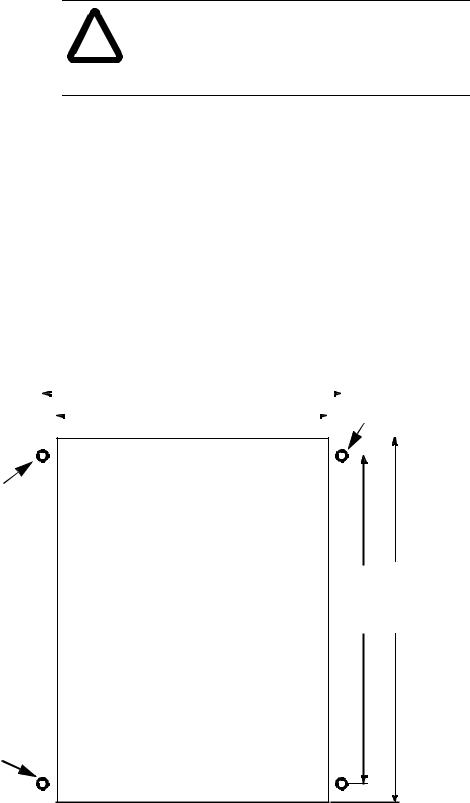
The module is designed for mounting in a cutout on the door of an enclosure. The cutout and drilling dimensions for the module are shown on the following page. We have also included a full-size tearout mounting template (appendix D) for your convenience.
When locating the cutout on the enclosure door:
•Provide 139.7 mm (5.5 in) clearance behind the enclosure door and 50.8 mm (2.0 in) electrical clearance above and below the module housing.
|
ATTENTION: To keep the module temperature |
! |
within the specified range, enclosure temperature must |
be between 0 to 55° (32 to 131° F). |
|
|
|
Publication 1747-6.1
2-2 |
Installation and Power Up |
•Before drilling in the enclosure door, all power to the enclosure must be disconnected. Make sure the drill bit does not contact equipment and cause damage.
ATTENTION: The module has ventilation holes on the top and bottom of the back cover. If you make
! additional holes in the enclosure, cover the module ventilation holes to protect against metal shavings entering the module housing.
• Do not remove top label until after installation.
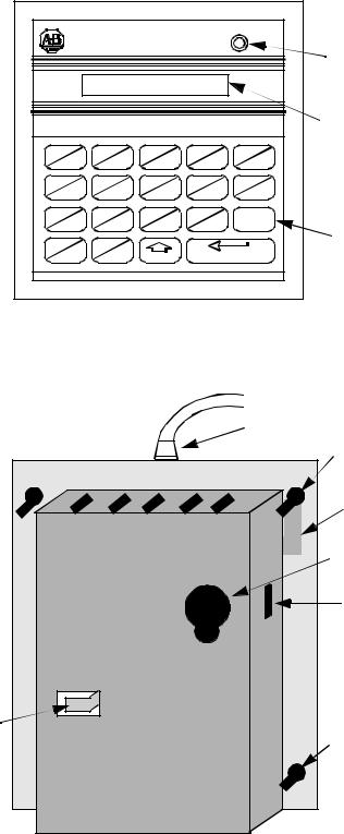
• A strain relief tab on the back of the module helps reduce stress on the interconnect cable when the door is opened. Once the module is installed, insert the cable under the tab and bend the tab downward to secure the cable.
• The module has a .8 Nm (7.0 in-lb) mounting torque.
• Insure that the module is grounded. If the DTAM is mounted to a non-conductive surface, attach a #8 AWG wire from the DTAM grounding screw to the SLC chassis.
Prepare a cutout for your enclosure door using the measurements shown below. See the template in Appendix D.
|
|
|
104.8 mm |
|
|
|
|
|
|
Scrape paint |
||
|
|
|
(4.125 in.) |
|
|
|
|
|
|
to ensure |
||
|
|
|
|
|
||||||||
|
|
|
|
|
|
|
|
|
|
|
good |
|
|
|
|
|
|
|
|
|
|
|
|
||
|
|
|
95.76 mm |
|
|
|
|
|
|
|
||
|
|
|
(3.77 in.) |
|
|
|
|
|
|
|
ground. |
|
|
|
|
|
|
|
|
|
|
|
|
|
|
|
|
|
|
|
|
|
|
|
|
|
|
|
|
|
|
|
|
|
|
|
|
|
|
|
|
|
|
|
|
|
|
|
|
|
|
|
|
|
Scrape paint to ensure good ground.
114.3 mm (4.5 in.) |
|
128.5 mm (5.06 in.) |
|
|
|
3.86 mm dia.
(0.152 in.)
4 holes
Publication 1747-6.1
Installation and Power Up |
2-3 |
COMM |
Module/Status |
Indicator |
LCD |
Display |
Keypad |
Cable Socket
|
Grounding |
|
|
Screw |
|
|
Grounding |
|
|
Foil |
|
|
Access Port |
|
|
Access Hole |
|
Strain Relief |
Mounting |
|
Tab |
||
Screws (4) |
||
|
||
|
Publication 1747-6.1 |
2-4 |
Installation and Power Up |
Connecting Your
Equipment
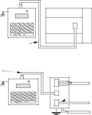
Connect the module to your system as shown below:
Point-to-Point Connection to a SLC 500 Family Processor
DTAM |
CH |
Interconnect Cable |
1.8 m (6 ft.) 1747-C10 |
Processor |
Communications |
Port |
Connection to a DH485 Network |
|
|
|
Interconnect Cable |
Link Coupler |
|
|
1.8 m (6 ft.) 1747-C10 |
1747-AIC |
|
|
DTAM |
|
|
|
CH |
|
Communication |
|
Peripheral |
Cable |
||
|
|||
|
J2 |
|
|
|
|
1747-C11 |
|
|
|
To Processor |
|
|
Earth Ground |
To optional 24V dc |
|
|
Power Supply |
||
|
|
Publication 1747-6.1
Installation and Power Up |
2-5 |
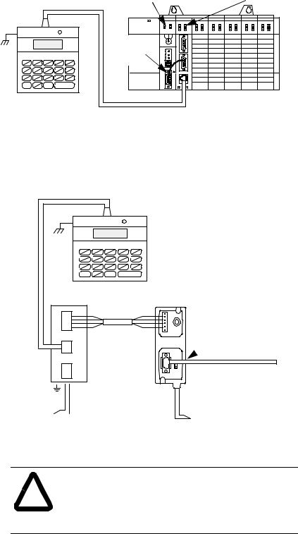
You can connect the DTAM module to an SLC 5/04 or later processor using either of the following methods.
Connection to a DH485 Network Using an Interface Module
Interconnect Cable |
SLC 5/04 Processor |
Interface Module |
|
(1747-L542) |
(1747-KE) |
||
1.8 m (6 ft.) 1747-C10 |
|||
|
|
DTAM
9-pin to 9-pin
Connector
CH
(1747-CP3)
Connection to a DH485 Network Using Link Couplers
Interconnect Cable 1.8 m (6 ft.) 1747-C10
DTAM
CH
Link Coupler |
Advanced Interface Coupler |
|
1747-AIC |
|
1761-NET-AIC |
|
|
|
|
|
|
Communications
Cable |
1747-CP3 |
|
|
Belden 9842 |
|
|
To SLC 5/04 Processor |
Earth Ground
To 24V dc
Power Supply To 24V dc
Power Supply
ATTENTION: The DTAM module end of the interconnect cable has pins that carry 24V dc.
!Disconnect the cable at the processor or link coupler to guard against connector short circuits and possible damage to the processor.
Publication 1747-6.1
2-6 |
Installation and Power Up |
Module Configuration
and Adjustments
The module’s access port and access hole allow you to adjust the LCD contrast and select the operational mode. Refer to chapter 5 to determine which mode to select, then return to this section to make the physical setting.
The module is shipped from the factory with the jumper installed between terminals 1 and 2 to configure the module for the Modify operational mode.
|
|
|
|
|
|
|
|
|
Header |
||||||||
|
|
|
|
|
|
|
|
|
|
|
|
|
|
|
|
|
|
Jumper |
|
|
|
|
|
|
|
Jumper |
3 |
|
|
|
|
|
|
||
|
|
|
|
|
|
|
2 |
|
|
|
|
|
|
||||
|
|
|
|
|
|
|
|
|
|
|
|
|
|
|
|
|
|
|
|
|
|
|
|
|
|
|
|
|
|
|
|
|
|
|
|
|
|
|
|
|
|
|
|
|
|
|
|
|
|
|
|
|
|
|
|
|
|
|
|
|
|
|
|
|
|
|
|
|
|
|
|
|
|
|
|
|
|
|
|
|
|
|
1 |
|
|
|
|
|
|
|
|
|
|
|
|
|
|
|
|
|
|
|
|
|
|
|
|
|
|
|
|
|
|
|
|
|
|
|
|
|
|
|
|
|
|
|
|
|
|
|
|
|
|
|
|
|
|
|
|
|
|
|
|
|
|
|
LCD Contrast |
|
|
|
|
Plug |
|||||||||
|
|
|
Adjust Pot |
|
|
|
|
|
|
|
|
|
|||||
|
Access Port View |
|
Access Hole View |
||||||||||||||
|
|
||||||||||||||||
To configure the module for the Monitor mode, either connect the jumper between terminals 1 and 3 (leaving the jumper installed in the module) or completely remove the jumper. You may either leave the header in place and make the connection via the access port and access hole, or temporarily remove the header from the module by pulling it off of the plug. If you choose the latter method, return the header to the plug once the connection is made.
|
|
|
|
|
|
|
|
|
|
|
Header |
|
|
|
|
|
|
|
|
|
|
|
|
|
|
|
|
|
|
|
|
|
3 |
|
|
|
|
|
|
||
Jumper |
|
|
|
|
|
|
|
|
|
Jumper |
|
|
2 |
|
|
|
|
|
|
|
|
|
|
|
|
|
|
|
|
|
|
|
|
|
|
|
|
||||
|
|
|
|
|
|
|
|
|
|
|
|
|
|
|
|
|||||
|
|
|
|
|
|
|
|
|
|
|
|
|
|
|
|
|
|
|
|
|
|
|
|
|
|
|
|
|
|
|
|
|
|
|
|
|
|
|
|
|
|
|
|
|
|
|
|
|
|
|
|
|
|
|
|
1 |
|
|
|
|
|
|
|
|
|
|
|
|
|
|
|
|
|
|
|
|
|
|
|
|
|
|
|
|
|
|
|
|
|
|
|
|
|
|
|
|
|
|
|
|
|
|
|
|
|
|
|
|
|
|
|
|
|
|
|
|
|
|
|
|
|
|
|
|
|
|
|
|
|
|
|
|
|
|
|
|
|
|
|
|
|
|
|
|
|
|
|
|
|
|
|
|
|
|
|
|
|
|
|
|
|
|
|
|
|
|
|
|
|
|
|
LCD Contrast |
|
|
|
|
|
Plug |
||||||||||
|
|
|
|
Adjust Pot |
|
|
|
|
|
|||||||||||
|
|
|
|
|
|
|
|
|
|
|
|
|
|
|||||||
|
|
Access Port View |
|
|
Access Hole View |
|||||||||||||||
|
|
|
|
|||||||||||||||||
Publication 1747-6.1
Installation and Power Up |
2-7 |
The jumper may be removed and an externally mounted user-supplied key switch connected.
Modify |
Monitor |
|
|
|
Terminal 3 is |
|
|
|
|||
|
|
|
unused. |
||
Mode |
Mode |
|
|
|
|
|
|
|
|
1.83 m (6 ft.)  Maximum distance
LCD Contrast |
|
Access Port View |
Adjust Pot |
|
|
ATTENTION: To avoid damaging the module, when you wire an external keyswitch for mode control, use
!an isolated switching device. Do not apply power to the terminals.
ATTENTION: To avoid damaging the module, when you change the mode select jumper, disconnect power from the module. Move the top lead of the jumper between terminals 2 and 3. Always leave the lead attached to the bottom terminal (terminal 1) connected.
Important: After you have set up the module for your application, to prevent unauthorized access to data files, connect the jumper for the Monitor mode or wire the key switch as shown .
Publication 1747-6.1

2-8 |
Installation and Power Up |
Power-Up Sequence
When the module is plugged into a processor or link coupler for the first time, the following sequence occurs:
1.The Communications LED illuminates solid red.
2.The module performs diagnostic self tests.
3.When the tests are complete, the Communications LED turns off, and the LCD displays:
Enter Network
Working . . .
If the module fails any of the self diagnostic tests, refer to chapter 9, Troubleshooting, for a list of error and fault codes.
4. The Communications LED flashes green, and the LCD displays:
RDY>
5.After a successful power-up, the display shows the ready prompt. You can now perform any of the following functions:
•Change the Module Setup. Refer to chapter 3, Module Setup Procedure.
•Initiate communications with a SLC 500 family processor. Refer to chapter 4, Attaching to a Processor.
•Clear an existing Quick Recall Function. Refer to chapter 6,
Quick Recall Functions.
•Observe and respond to a displayed message. Refer to chapter 8, Message Capability.
Publication 1747-6.1
Chapter 3
Module Setup Procedure
This chapter describes the setup procedures for configuring the operation of the module for specific applications. The topics covered are:
•language for the module display
•module node address
•module baud rate
•Auto Attach function
•LCD backlighting
•Monitor Override function
•module reset function
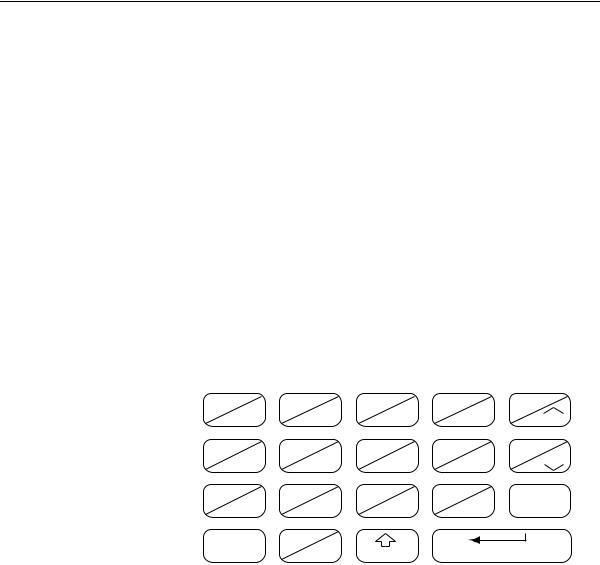
Keyboard Description The keyboard is shown below. Details about individual key functions are described at the point of use in this manual.
I |
O |
B |
PRE |
LEN |
|
7 |
8 |
9 |
NEXT |
INC |
|
T |
C |
R |
ACC |
POS |
|
4 |
5 |
6 |
PREV |
DEC |
|
|
|||||
N |
M |
. |
I |
F ( ) |
|
1 |
2 |
3 |
+/- |
||
|
|||||
ESC |
: |
SHIFT |
ENTER |
||
0 |
|||||
|
|||||
Key |
Explanation |
|
|
0 - 9 |
Numeric Keys |
|
|
I |
Input Image Data File |
|
|
O |
Output Image Data File |
|
|
B |
Bit Data File |
|
|
T |
Timer Data File |
|
|
C |
Counter Data File |
|
|
R |
Control Data File |
|
|
N |
Integer Data File |
|
|
M |
Reserved for Future Use |
|
|
Publication 1747-6.1
3-2 |
Module Setup Procedure |
Factory Default
Settings
Key |
Explanation |
|
|
: |
Data File Addressing Element Delimiter |
|
|
. |
Data File Addressing Word Delimiter |
|
|
/ |
Data File Addressing Bit Delimiter |
|
|
PRE |
Timer/Counter Preset Word |
|
|
ACC |
Timer/Counter Accumulator Word |
|
|
LEN |
Control Register File Length Word |
|
|
POS |
Control Register Pointer Position Word |
|
|
+/- |
Positive/Negative Signed Integer |
|
|
NEXT |
Increment to Next Logical Address |
|
|
PREV |
Decrement to Previous Logical Address |
|
|
INC |
Increment Data Value or Control Bit |
|
|
DEC |
Decrement Data Value or Control Bit |
|
|
F( ) |
Function Key |
|
|
ESC |
Escape Key |
|
|
SHIFT |
Shift to Upper Case |
|
|
ENTER |
Enter Desired Parameter |
|
|
The module is shipped from the factory with the following default settings:
Feature |
Default Setting |
|
|
Language |
English |
|
|
DTAM Node Address |
0 |
|
|
Baud Rate |
19200 |
|
|
Auto Attach |
Off |
|
|
LCD Backlighting |
On |
|
|
Monitor Override |
Off |
|
|
Publication 1747-6.1

Module Setup Procedure |
3-3 |
Entering the Setup
Mode
To change the Setup configuration, the module must be in the Modify mode. This is indicated by the flashing green Communications LED.
To review the Setup configuration, the module must be in the Modify mode. Press the >(17(5@ key repeatedly until the procedure is complete.
After the module is powered up and the self diagnostics are completed, the LCD displays the Ready Unattached screen:
RDY>
To enter the Setup mode:
Press > @>,1&@ simultaneously, and hold until the display shows:
Modify Setup
Confirm?
This display prompts you to confirm:
•If you want to initiate the setup procedure:
Press >(17(5@
•If you want to return to the previous display:
Press >(6&@
When the setup mode has been initiated, the Communications LED turns off.
Important: Once you initiated the setup procedure, only the >,1&@, >'(&@ and >(17(5@ keys are functional.
If the unit disconnects, a power failure occurs, or the module is switched from Modify to Monitor mode while in the setup procedure, no new parameters are saved.
Publication 1747-6.1

3-4 |
Module Setup Procedure |
Selecting the
Language
Selecting the Node
Address
You can configure the module to display all prompts and data in one of six languages. The available languages are: English, Spanish, Japanese, Italian, German and French. The default language displayed is English:
Select Language
ENGLISH
• To change the language displayed:
Press >,1&@ or >'(&@
•To accept the displayed language:
Press >(17(5@
Once you have selected a language, the module immediately begins to display in that language.
The node address is the communications identifier on the DH485 network for this module. Valid node addresses range from 0 through 31. The default node address displayed is 0.
Important: Care must be taken when selecting a node address. Do not duplicate the address of a processor or another device on the DH485 network.
Select DTAM Addr
0
•To change the node address: Press [,1&] or ['(&].
•To accept the displayed address:
Press >(17(5@
Publication 1747-6.1

Module Setup Procedure |
3-5 |
Setting the Baud Rate This is the communications rate for the module. Available baud rates are: 1200, 2400, 9600 and 19200 baud. The default baud rate displayed is 19200.
Important: All devices on the DH485 network, including the module, must be set to the same baud rate.
Setting the Auto
Attach Function
Select Baud Rate
19200
•To scroll through the available baud rates: Press [,1&] or ['(&].
•To accept the displayed baud rate:
Press [(17(5].
This selection determines how the module attaches to a processor. The default selection is Off.
When the function is set to Off, you are required to manually attach to a processor each time the module is powered up.
When the function is set to On, the module attempts to attach to the address of the last processor it was logically attached to or to the default node address of one.
Set Auto Attach
OFF
•To toggle between On and Off: Press [,1&] or ['(&].
•To accept the setting:
Press [(17(5].
Publication 1747-6.1

3-6 |
Module Setup Procedure |
Backlighting the LCD
Setting the Monitor
Override Function
This selection controls the illumination for the LCD. The default selection is On:
Set Backlighting
ON
•To toggle between On and Off: Press [,1&] or ['(&].
•To accept the setting:
Press [(17(5].
The Monitor Override feature allows you to write to selected data file addresses while in the Monitor mode. Refer to chapter 5, Monitoring and Modifying Data and chapter 6, Quick Recall Functions. The default selection is Off:
Monitor Override
OFF
•To toggle between On and Off: Press [,1&] or ['(&].
•To accept the setting:
Press [(17(5].
Publication 1747-6.1

Module Setup Procedure |
3-7 |
Accepting Module
Setup Parameters
Using the Module
Reset
If you accept the new configuration, the parameters are written to the module’s nonvolatile memory. If you reject the new parameters, the previous setup configuration remains unchanged.
Accept Setup
Confirm?
•To accept the configuration: Press [(17(5].
•To reject the configuration: Press [(6&].
The module then performs a reset and self test. Upon completion, the LCD displays one of the two Ready screens. Refer to chapter 4, Attaching to a Processor, for a description of these displays.
The module reset key sequence is available at any time and during any function sequence. Use it when a nonrecoverable fault condition error code is displayed or when the module appears to be nonfunctional. Refer to chapter 9, Troubleshooting, for fault conditions and error codes.
To reset the module:
Press [ ] [ ] [(17(5] simultaneously and hold until this message displays:
DTAM Reset
In Progress
This reset message continues to display during the reset procedure and the diagnostic test which follows. Upon completion, one of the Ready screens displays.
Publication 1747-6.1
3-8 |
Module Setup Procedure |
Publication 1747-6.1
Loading...