

Page 1

Arena®Packaging
USER’S GUIDE
PUBLICATION ARENPK-UM001F-EN-P–November 2007
Supersedes Publication ARENPK-UM001E-EN-P
Page 2

Contact Rockwell
Customer Support Telephone — 1.440.646.3434
Online Support — http://www.rockwellautomation.com/support/
Copyright Notice
Trademark Notices
Other Trademarks
Warran ty
© 2007 Rockwell Automation Technologies, Inc. All rights reserved. Printed in USA.
This document and any accompanying Rockwell Software products are copyrighted by Rockwell Automation
Technologies, Inc. Any reproduction and/or distribution without prior written consent from Rockwell Automation
Technologies, Inc. is strictly prohibited. Please refer to the license agreement for details.
Arena, Rockwell Automation, and SIMAN are registered trademarks of Rockwell Automation, Inc.
ActiveX, Microsoft, Microsoft Access, SQL Server, Visual Basic, Visual C++, Visual SourceSafe, Windows, Windows
ME, Windows NT, Windows 2000, Windows Server 2003, and Windows XP are either registered trademarks or
trademarks of Microsoft Corporation in the United States and/or other countries.
Adobe, Acrobat, and Reader are either registered trademarks or trademarks of Adobe Systems Incorporated in the
United States and/or other countries.
ControlNet is a registered trademark of ControlNet International.
DeviceNet is a trademark of the Open DeviceNet Vendor Association, Inc. (ODVA)
Ethernet is a registered trademark of Digital Equipment Corporation, Intel, and Xerox Corporation
OLE for Process Control (OPC) is a registered trademark of the OPC Foundation.
Oracle, SQL*Net, and SQL*Plus are registered trademarks of Oracle Corporation.
All other trademarks are the property of their respective holders and are hereby acknowledged.
This product is warranted in accordance with the product license. The product’s performance may be affected by system
configuration, the application being performed, operator control, maintenance and other related factors. Rockwell
Automation is not responsible for these intervening factors. The instructions in this document do not cover all the
details or variations in the equipment, procedure, or process described, nor do they provide directions for meeting every
possible contingency during installation, operation, or maintenance. This product’s implementation may vary among
users.
This document is current as of the time of release of the product; however, the accompanying software may have
changed since the release. Rockwell Automation, Inc. reserves the right to change any information contained in this
document or the software at anytime without prior notice. It is your responsibility to obtain the most current information
available from Rockwell when installing or using this product.
Version: 12.00.00 (CPR9)
Modified: October 8, 2007 10:39 am
ii
Page 3

Contents
1 • Welcome to the Arena Packaging Template 1
What is the Arena Packaging template?. . . . . . . . . . . . . . . . . . . . . . . . . . . . . . . . . . . . . 1
Intended audience. . . . . . . . . . . . . . . . . . . . . . . . . . . . . . . . . . . . . . . . . . . . . . . . . . . . . . 1
Where can I go for help? . . . . . . . . . . . . . . . . . . . . . . . . . . . . . . . . . . . . . . . . . . . . . . . . 1
Reference the user’s guides . . . . . . . . . . . . . . . . . . . . . . . . . . . . . . . . . . . . . . . . . . 1
Explore our examples . . . . . . . . . . . . . . . . . . . . . . . . . . . . . . . . . . . . . . . . . . . . . . . 2
Get help. . . . . . . . . . . . . . . . . . . . . . . . . . . . . . . . . . . . . . . . . . . . . . . . . . . . . . . . . . 2
Use the HSMARTs library . . . . . . . . . . . . . . . . . . . . . . . . . . . . . . . . . . . . . . . . . . . 2
Access the Arena Symbol Factory . . . . . . . . . . . . . . . . . . . . . . . . . . . . . . . . . . . . . 2
Get phone support. . . . . . . . . . . . . . . . . . . . . . . . . . . . . . . . . . . . . . . . . . . . . . . . . . 3
Get Web support. . . . . . . . . . . . . . . . . . . . . . . . . . . . . . . . . . . . . . . . . . . . . . . . . . . 3
Get training . . . . . . . . . . . . . . . . . . . . . . . . . . . . . . . . . . . . . . . . . . . . . . . . . . . . . . . 4
Get consulting services. . . . . . . . . . . . . . . . . . . . . . . . . . . . . . . . . . . . . . . . . . . . . . 4
Contact us . . . . . . . . . . . . . . . . . . . . . . . . . . . . . . . . . . . . . . . . . . . . . . . . . . . . . . . . 4
2 • General Concepts 5
Template overview. . . . . . . . . . . . . . . . . . . . . . . . . . . . . . . . . . . . . . . . . . . . . . . . . . . . . 5
Template framework and modeling methodology . . . . . . . . . . . . . . . . . . . . . . . . . . . . . 6
•
Step 1
Step 2
Step 3
Step 4
Step 5
Place and connect equipment . . . . . . . . . . . . . . . . . . . . . . . . . . . . . . . . . . 6
•
Define equipment behavior. . . . . . . . . . . . . . . . . . . . . . . . . . . . . . . . . . . . 8
•
Run the model. . . . . . . . . . . . . . . . . . . . . . . . . . . . . . . . . . . . . . . . . . . . . 10
•
View automatic statistics . . . . . . . . . . . . . . . . . . . . . . . . . . . . . . . . . . . . 13
•
Experiment with complex strategies. . . . . . . . . . . . . . . . . . . . . . . . . . . . 15
3 • The Packaging Panel 21
Panel modules . . . . . . . . . . . . . . . . . . . . . . . . . . . . . . . . . . . . . . . . . . . . . . . . . . . . . . . 21
Actions module. . . . . . . . . . . . . . . . . . . . . . . . . . . . . . . . . . . . . . . . . . . . . . . . . . . 21
Conveyor module . . . . . . . . . . . . . . . . . . . . . . . . . . . . . . . . . . . . . . . . . . . . . . . . . 22
Conveyor Link (CLink) module . . . . . . . . . . . . . . . . . . . . . . . . . . . . . . . . . . . . . . 23
Label module . . . . . . . . . . . . . . . . . . . . . . . . . . . . . . . . . . . . . . . . . . . . . . . . . . . . 23
Machine module . . . . . . . . . . . . . . . . . . . . . . . . . . . . . . . . . . . . . . . . . . . . . . . . . . 23
Machine Link (MLink) module . . . . . . . . . . . . . . . . . . . . . . . . . . . . . . . . . . . . . . 27
Merge module. . . . . . . . . . . . . . . . . . . . . . . . . . . . . . . . . . . . . . . . . . . . . . . . . . . . 28
Operator module . . . . . . . . . . . . . . . . . . . . . . . . . . . . . . . . . . . . . . . . . . . . . . . . . . 28
Operator Group module . . . . . . . . . . . . . . . . . . . . . . . . . . . . . . . . . . . . . . . . . . . . 29
Operator Schedule module . . . . . . . . . . . . . . . . . . . . . . . . . . . . . . . . . . . . . . . . . . 30
iii
Page 4

ARENA PACKAGING TEMPLATE USER’S GUIDE
• • • • •
Palletizer module . . . . . . . . . . . . . . . . . . . . . . . . . . . . . . . . . . . . . . . . . . . . . . . . . 31
Product module. . . . . . . . . . . . . . . . . . . . . . . . . . . . . . . . . . . . . . . . . . . . . . . . . . . 35
Production Plans module . . . . . . . . . . . . . . . . . . . . . . . . . . . . . . . . . . . . . . . . . . . 36
Simulate module . . . . . . . . . . . . . . . . . . . . . . . . . . . . . . . . . . . . . . . . . . . . . . . . . . 36
Split module . . . . . . . . . . . . . . . . . . . . . . . . . . . . . . . . . . . . . . . . . . . . . . . . . . . . . 37
Storage module . . . . . . . . . . . . . . . . . . . . . . . . . . . . . . . . . . . . . . . . . . . . . . . . . . . 37
Switch module . . . . . . . . . . . . . . . . . . . . . . . . . . . . . . . . . . . . . . . . . . . . . . . . . . . 38
Tank module . . . . . . . . . . . . . . . . . . . . . . . . . . . . . . . . . . . . . . . . . . . . . . . . . . . . . 38
Valve module . . . . . . . . . . . . . . . . . . . . . . . . . . . . . . . . . . . . . . . . . . . . . . . . . . . . 39
Common module dialogs . . . . . . . . . . . . . . . . . . . . . . . . . . . . . . . . . . . . . . . . . . . . . . . 39
Actions dialog. . . . . . . . . . . . . . . . . . . . . . . . . . . . . . . . . . . . . . . . . . . . . . . . . . . . 39
Animation dialog . . . . . . . . . . . . . . . . . . . . . . . . . . . . . . . . . . . . . . . . . . . . . . . . . 40
Controls dialog . . . . . . . . . . . . . . . . . . . . . . . . . . . . . . . . . . . . . . . . . . . . . . . . . . . 40
Costs dialog . . . . . . . . . . . . . . . . . . . . . . . . . . . . . . . . . . . . . . . . . . . . . . . . . . . . . 41
Loss dialog . . . . . . . . . . . . . . . . . . . . . . . . . . . . . . . . . . . . . . . . . . . . . . . . . . . . . . 41
Operators dialog . . . . . . . . . . . . . . . . . . . . . . . . . . . . . . . . . . . . . . . . . . . . . . . . . . 42
Production and Changeovers dialog . . . . . . . . . . . . . . . . . . . . . . . . . . . . . . . . . . . 43
Reliability dialog . . . . . . . . . . . . . . . . . . . . . . . . . . . . . . . . . . . . . . . . . . . . . . . . . 44
Run Options dialog. . . . . . . . . . . . . . . . . . . . . . . . . . . . . . . . . . . . . . . . . . . . . . . . 44
Scheduled Stops dialog. . . . . . . . . . . . . . . . . . . . . . . . . . . . . . . . . . . . . . . . . . . . . 45
Sensors dialog. . . . . . . . . . . . . . . . . . . . . . . . . . . . . . . . . . . . . . . . . . . . . . . . . . . . 45
4 • Statistics 47
Overview . . . . . . . . . . . . . . . . . . . . . . . . . . . . . . . . . . . . . . . . . . . . . . . . . . . . . . . . . . . 47
Selecting the statistics to report . . . . . . . . . . . . . . . . . . . . . . . . . . . . . . . . . . . . . . . . . . 48
Statistic descriptions. . . . . . . . . . . . . . . . . . . . . . . . . . . . . . . . . . . . . . . . . . . . . . . . . . . 49
Machine statistics . . . . . . . . . . . . . . . . . . . . . . . . . . . . . . . . . . . . . . . . . . . . . . . . . 49
Conveyor statistics . . . . . . . . . . . . . . . . . . . . . . . . . . . . . . . . . . . . . . . . . . . . . . . . 54
Palletizer statistics . . . . . . . . . . . . . . . . . . . . . . . . . . . . . . . . . . . . . . . . . . . . . . . . 59
Storage statistics . . . . . . . . . . . . . . . . . . . . . . . . . . . . . . . . . . . . . . . . . . . . . . . . . . 64
Operator statistics . . . . . . . . . . . . . . . . . . . . . . . . . . . . . . . . . . . . . . . . . . . . . . . . . 64
Operator Group statistics . . . . . . . . . . . . . . . . . . . . . . . . . . . . . . . . . . . . . . . . . . . 65
5 • Variables 67
Overview . . . . . . . . . . . . . . . . . . . . . . . . . . . . . . . . . . . . . . . . . . . . . . . . . . . . . . . . . . . 67
Organization. . . . . . . . . . . . . . . . . . . . . . . . . . . . . . . . . . . . . . . . . . . . . . . . . . . . . . . . . 67
Assigning and referencing Arena Packaging template variables . . . . . . . . . . . . . 67
Updating Arena Packaging template variables. . . . . . . . . . . . . . . . . . . . . . . . . . . 67
Variables. . . . . . . . . . . . . . . . . . . . . . . . . . . . . . . . . . . . . . . . . . . . . . . . . . . . . . . . 67
Assigning and referencing variables . . . . . . . . . . . . . . . . . . . . . . . . . . . . . . . . . . . . . . 68
Assigning values to variables . . . . . . . . . . . . . . . . . . . . . . . . . . . . . . . . . . . . . . . . 68
iv
Page 5

CONTENTS
Referencing variables . . . . . . . . . . . . . . . . . . . . . . . . . . . . . . . . . . . . . . . . . . . . . . 68
References in Arena and SIMAN template modules . . . . . . . . . . . . . . . . . . . . . . 71
References in Arena Packaging template modules. . . . . . . . . . . . . . . . . . . . . . . . 72
Updating variables . . . . . . . . . . . . . . . . . . . . . . . . . . . . . . . . . . . . . . . . . . . . . . . . . . . . 72
Updating variables for animation . . . . . . . . . . . . . . . . . . . . . . . . . . . . . . . . . . . . . 72
Updating variables at a specific time—The Update action . . . . . . . . . . . . . . . . . 73
Variables . . . . . . . . . . . . . . . . . . . . . . . . . . . . . . . . . . . . . . . . . . . . . . . . . . . . . . . . . . . 74
Conveyor variables . . . . . . . . . . . . . . . . . . . . . . . . . . . . . . . . . . . . . . . . . . . . . . . . 75
Conveyor Link variable . . . . . . . . . . . . . . . . . . . . . . . . . . . . . . . . . . . . . . . . . . . . 77
Machine variables. . . . . . . . . . . . . . . . . . . . . . . . . . . . . . . . . . . . . . . . . . . . . . . . . 77
Palletizer variables . . . . . . . . . . . . . . . . . . . . . . . . . . . . . . . . . . . . . . . . . . . . . . . . 80
Storage variable . . . . . . . . . . . . . . . . . . . . . . . . . . . . . . . . . . . . . . . . . . . . . . . . . . 82
Switch variable . . . . . . . . . . . . . . . . . . . . . . . . . . . . . . . . . . . . . . . . . . . . . . . . . . . 82
Tank variables. . . . . . . . . . . . . . . . . . . . . . . . . . . . . . . . . . . . . . . . . . . . . . . . . . . . 83
Valve variable. . . . . . . . . . . . . . . . . . . . . . . . . . . . . . . . . . . . . . . . . . . . . . . . . . . . 83
A • Equipment Reliability and Loss 85
Defining reliability . . . . . . . . . . . . . . . . . . . . . . . . . . . . . . . . . . . . . . . . . . . . . . . . . . . . 85
Using expected uptime . . . . . . . . . . . . . . . . . . . . . . . . . . . . . . . . . . . . . . . . . . . . . 85
Using reliability over a time span. . . . . . . . . . . . . . . . . . . . . . . . . . . . . . . . . . . . . 86
Using individual failure streams. . . . . . . . . . . . . . . . . . . . . . . . . . . . . . . . . . . . . . 88
Questions and answers about reliability . . . . . . . . . . . . . . . . . . . . . . . . . . . . . . . . 90
Defining loss . . . . . . . . . . . . . . . . . . . . . . . . . . . . . . . . . . . . . . . . . . . . . . . . . . . . . . . . 91
Event-based loss . . . . . . . . . . . . . . . . . . . . . . . . . . . . . . . . . . . . . . . . . . . . . . . . . . 92
Production-based loss . . . . . . . . . . . . . . . . . . . . . . . . . . . . . . . . . . . . . . . . . . . . . . 93
Questions and answers about loss . . . . . . . . . . . . . . . . . . . . . . . . . . . . . . . . . . . . 96
• • • • •
B • Placing Animation 99
The Animation dialog . . . . . . . . . . . . . . . . . . . . . . . . . . . . . . . . . . . . . . . . . . . . . . . . 100
State or Level Indicator . . . . . . . . . . . . . . . . . . . . . . . . . . . . . . . . . . . . . . . . . . . 100
Blocked/Starved symbols . . . . . . . . . . . . . . . . . . . . . . . . . . . . . . . . . . . . . . . . . . 100
Product picture . . . . . . . . . . . . . . . . . . . . . . . . . . . . . . . . . . . . . . . . . . . . . . . . . . 101
Variables or statistics table. . . . . . . . . . . . . . . . . . . . . . . . . . . . . . . . . . . . . . . . . 102
Questions and answers about animation. . . . . . . . . . . . . . . . . . . . . . . . . . . . . . . 102
Index 103
v
Page 6

ARENA PACKAGING TEMPLATE USER’S GUIDE
• • • • •
vi
Page 7

1
Welcome to the Arena Packaging Template
What is the Arena Packaging template?
Arena Packaging is a simulation system developed by Rockwell Automation for the
performance analysis of high-speed, high-volume manufacturing systems.
The initial design of the Packaging template was developed by Ouroumoff Diffusion (a
consulting firm headquartered in Lyon, France) during a consulting engagement with
Pechiney CRV to analyze canning lines. The core algorithms of the product involved vital
input from the engineering staff at Pechiney. The final design of the Packaging template
then involved significant input by staff at Rockwell Automation as well as Michigan State
University’s School of Packaging.
Intended audience
The Arena Packaging template is designed for manufacturing or business process consultants and analysts and industrial or systems engineers. It is typically deployed as an enterprise business analysis and productivity tool.
We assume that you are familiar with the basic concepts and terms used in these types of
systems. You are interested in improving business or manufacturing productivity and are
responsible for evaluating and predicting the impact of proposed strategic and tactical
changes to help improve performance. A familiarity with computers and the Microsoft
Windows
in simulation is also helpful.
®
operating system is assumed. A familiarity with the concepts and terms used
1 • Welcome
®
Where can I go for help?
Our commitment to your success starts with the suite of learning aids and assistance we
provide for Arena. Whether you’re new to simulation or a seasoned veteran putting a new
tool to use, you’ll quickly feel at home with Arena Packaging.
Reference the user’s guides
The documentation set includes this manual, Arena Packaging Template User’s Guide,
which cover the product basics as well as the Arena User’s Guide, which covers the
standard product modules and offers an easy, “click-by-click” tutorial, and the Variables
Guide, a separate reference booklet providing complete descriptions of Arena variables
found in the Arena product templates.
1
Page 8

ARENA PACKAGING TEMPLATE USER’S GUIDE
• • • • •
D
OCUMENT CONVENTIONS
Throughout the guides, a number of style conventions are used to help identify material.
New terms and concepts may be emphasized by use of italics or bold; file menu paths are
in bold with a (>) separating the entries (e.g., go to Help > Arena Help); text you are
asked to type is shown in Courier Bold (e.g., in this field, type Work Week), and dialog
box and window button names are shown in bold (e.g., click OK).
Explore our examples
Arena is accompanied by a number of sample models that illustrate many of the
commonly used approaches for capturing the essence of manufacturing processes.
Examples are provided for both job shop and flow shop environments. For a description
of and list of Arena’s examples, go to Help > Arena Help. On the Contents tab, choose
Model Building Basics, and then select Viewing Arena Example Models.
Get help
Online help is always at your fingertips! Arena incorporates the latest in help features,
including What’s This? help that displays a brief description of fields in dialog boxes,
context-sensitive help on menu and toolbar buttons, and a help button on each of Arena’s
modules. Just refer to the Arena help table of contents and index for a list of all help
topics.
Use the HSMARTs library
As you craft models of your own manufacturing processes, use our HSMARTs library to
explore how to best use Arena. HSMARTs are a collection of small, self-contained models
that illustrate different aspects of modeling in Arena Packaging. We recommend you go
through these small files to see how concepts are implemented in actual models. For a list
of categories and their related HSMARTS, go to Help > Arena Help. On the Contents
tab, choose Template Help > Packaging > Arena Packaging Template > Learning
Arena Packaging Template with the HSMART Files.
Access the Arena Symbol Factory
Arena animations can be enhanced using Arena Symbol Factory’s extensive library of
over 4,000 symbols. These symbols can be used for entity, resource, transporter or global
pictures; or as graphic symbols within a model window. You can copy these symbols
directly to the Arena model window, add them to your own libraries (.plb files), or add
them to any of the Arena picture library files.
2
Page 9

1 • WELCOME TO THE ARENA PACKAGING TEMPLATE
Get phone support
Rockwell Automation’s support team of outstanding professionals provides top-notch
technical support—monitoring and tracking your experience with our simulation products
to pave the road to your success in understanding and improving your performance.
Rockwell Automation provides full support for the entire Arena family of products.
Questions concerning installation, how modules work, the use of the model editor, and the
use of the software are handled by technical support.
A
RENA TECHNICAL SUPPORT INCLUDES
(for users on active maintenance) a technical support hotline and e-mail address
staffed by full-time, experienced professionals
help with installation problems or questions related to the software’s requirements
troubleshooting
limited support regarding the interaction of Arena with other programs
support of the Arena Object Model, which is used in Microsoft Visual Basic for
Applications.
If you call the support line (1.440.646.3434), you should be at your computer and be
prepared to give the following information:
:
• • • • •
1 • Welcome
the product serial number
the product version number
the operating system you are using
the exact wording of any messages that appeared on your screen
a description of what happened and what you were doing when the problem occurred
a description of how you tried to solve the problem.
Get Web support
In addition to phone support, the Rockwell Automation Customer Support Center offers
extensive online knowledgebases of tech notes and frequently asked questions for support
of non-urgent issues. These databases are updated daily by our support specialists.
To receive regular e-mail messages with links to the latest tech notes, software updates,
and firmware updates for the products that are of interest to you or to submit an online
support request, go to support.rockwellautomation.com/supportrequests
And be sure to check the Arena User Zone section of our Web site at www.ArenaSimulation.com. The User Zone links to a peer-to-peer forum on Arena topics and has a link to a
download page where you can check for possible software updates (patches). If you can’t
find the answer you need, contact your local representative or Arena technical support.
.
3
Page 10

ARENA PACKAGING TEMPLATE USER’S GUIDE
• • • • •
Get training
Do you need training? Rockwell Automation offers a standard training course comprised
of lecture and hands-on workshops designed to introduce you to the fundamental concepts
of modeling with Arena.
We also offer customized training courses designed to meet your specific needs. These
courses can be held in our offices or yours, and we can accommodate one person or
twenty. You design the course that’s right for you! Simply contact our consulting services
group to discuss how we can help you achieve success in your simulation efforts.
Get consulting services
Rockwell Automation provides expert consulting and turnkey implementation of the
entire Arena product suite. Please call our offices for more information or e-mail ArenaInfo@ra.rockwell.com.
Contact us
We strive to help all of our customers become successful in their manufacturing improvement efforts. Toward this objective, we invite you to contact your local representative or
Rockwell Automation at any time that we may be of service to you.
Support E-mail: Arena-Support@ra.rockwell.com
Corporate E-mail: Arena-Info@ra.rockwell.com
Support Phone: 1.440.646.3434
URL: www.ArenaSimulation.com
URL: www.rockwellautomation.com
4
Page 11

2
General Concepts
Template overview
Arena Packaging is one of a family of application solution templates (ASTs) built on the
Arena simulation system. It is designed specifically for performing accurate and efficient
simulations of high-speed, high-volume manufacturing systems, where the processing rates
take place at hundreds, even thousands, of entities per minute. The Packaging template
enables users to build and run simulation models of high-speed processing lines quickly
and easily, and to analyze the results that these models produce.
To use the Arena Packaging template, you attach the Packaging panel to the Arena
development environment. The Packaging panel contains a collection of objects or
modules. Each module defines the logic, data, animation, and/or statistics collection for a
particular element in a model (e.g., machines, conveyors, operators).
The Packaging panel contains the following modules:
A Machine module for modeling the physical components of a line where the actual
processing or conversion of units takes place.
A Conveyor module for modeling the accumulating conveyors between machines
where units are transferred and buffered.
Machine Link and Conveyor Link modules for linking machines and conveyors
directly together.
Merge, Split, and Switch modules for modeling transfer points between conveyors
where product flow is split or combined (i.e., flow controls).
2 • General Concepts
Operator, Operator Group, and Operator Schedule modules for modeling the
availability and organization of labor in the system.
Palletizer and Storage modules for modeling the physical components of a line where
units are stored on or removed from pallets.
Val ve and Tank modules for modeling fluid constraints of filling operations.
Product and Production Plans modules for defining multiple products processed in a
system and their requirements.
An Actions module for performing actions on a high-speed system (e.g., changing run
speeds of machines, adjusting valves, adding pallets to a storage) using discrete
entities and logic.
A Label module for labeling a particular portion of the model logic, whereby discrete
entities may be sent easily to the label from other locations in the model.
5
Page 12
ARENA PACKAGING TEMPLATE USER’S GUIDE
• • • • •
A Simulate module for advanced model options (e.g., units of measure, statistic
collection switches).
Template framework and modeling methodology
Simulation studies are initiated because a decision maker or group of decision makers face
a problem and need a solution. You should begin a simulation project by first collecting
enough information and data to provide an adequate understanding of both the problem
and the system to be studied. Once that step is complete, you are then ready to formulate
models.
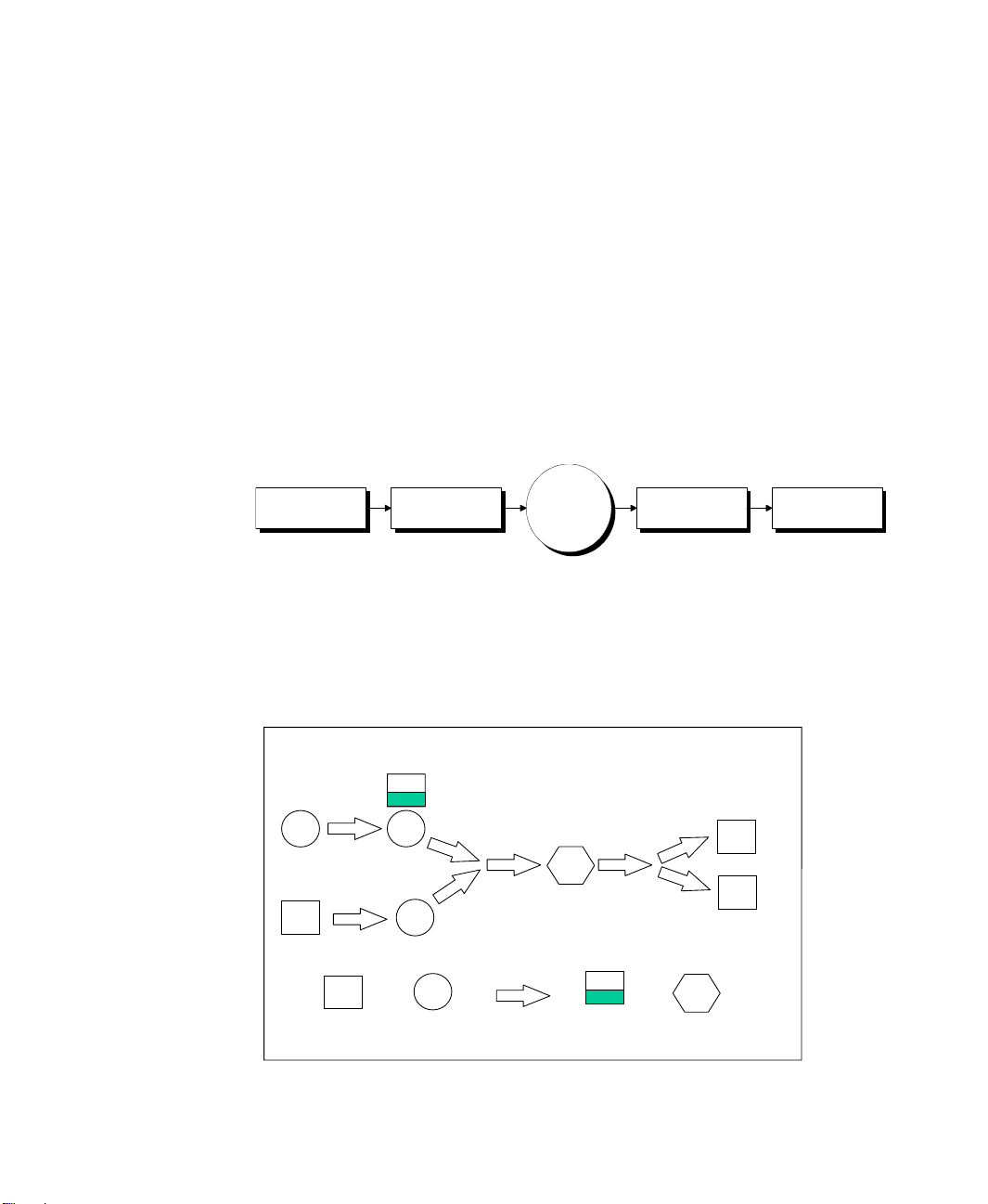
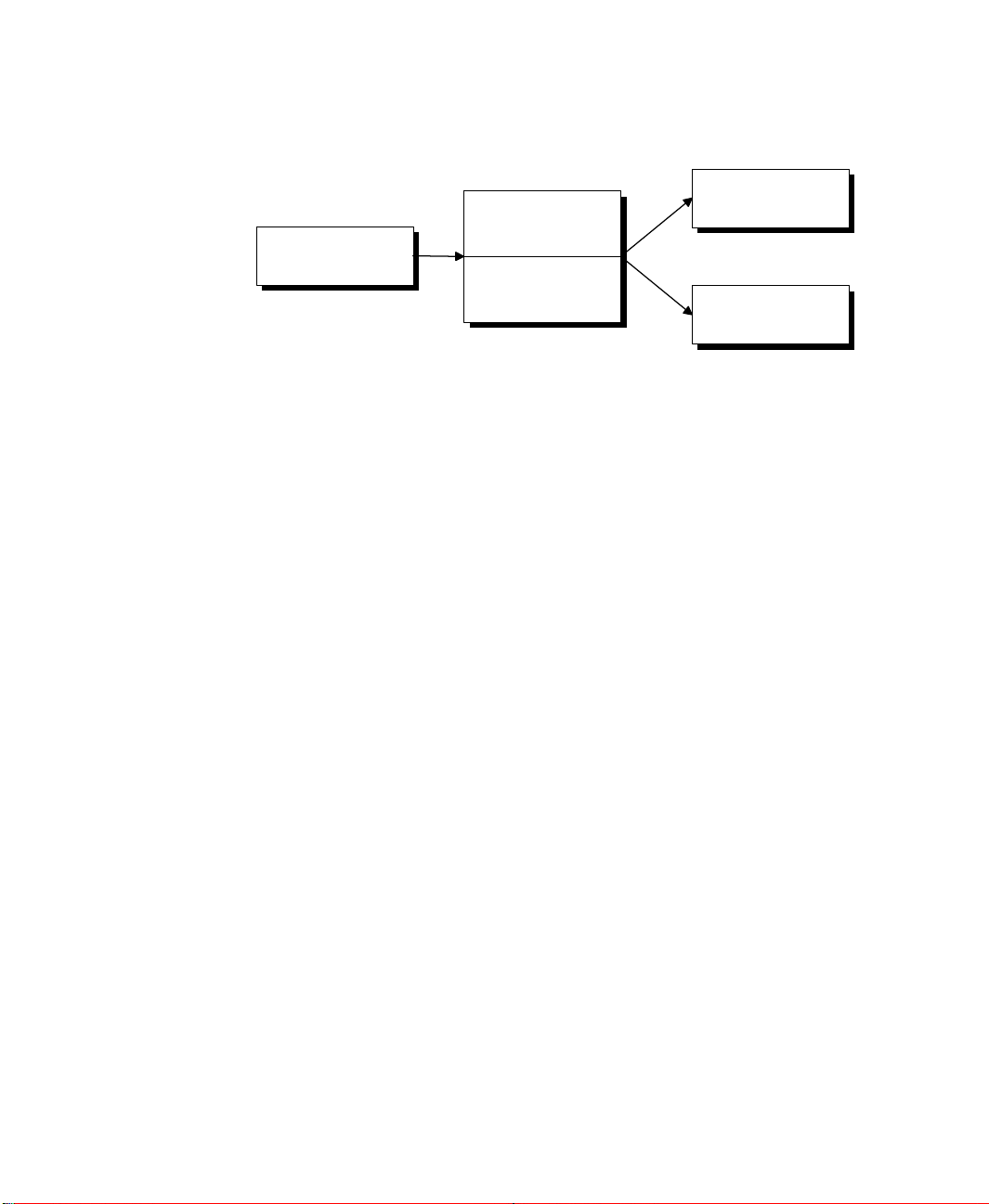
This section introduces a five-step modeling methodology for developing those simulation models in Arena Packaging. The steps of the methodology are illustrated in the
following diagram.
Place & Connect
Equipment
Define Equipment
Behavior
Run
the
Model
View Automatic
Statistics
Experiment with
Complex Strategies
Step 1 • Place and connect equipment
First, flowchart on paper the step-by-step sequence of your line as raw goods are converted
into finished product. For example, you might construct flowcharts of the machines,
conveyors, palletizers, merges, splits, etc., in your line similar to the flowchart below.
(De)Palletizer
Processing Step
Conveyor
Tank
Inspection
6
Page 13
2 • GENERAL CONCEPTS
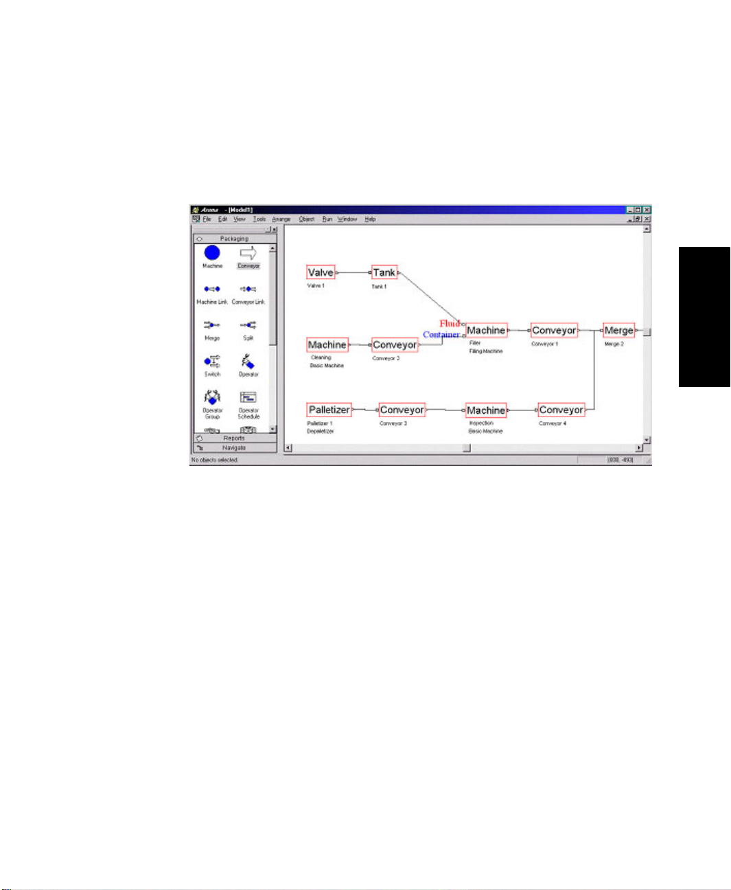
Once you have flowcharted your process, duplicate that flowchart in Arena by graphically
placing and connecting appropriate modules from the Packaging panel into an Arena
model window. To select a module, you simply drag and drop an icon in the panel onto the
workspace region where you want the module to be placed.
• • • • •
2 • General Concepts
HSMARTs are a collection of small models that illustrate modeling techniques. To learn
combinations of Packaging modules that are appropriate for specific situations, it is useful
to refer to the HSMART examples for Step 1.
Step 1 • Place and Connect Equipment
Processing
HSMART01: Basic Processing Operation
HSMART02: Basic Processing Operation Using a Non-accumulating
Conveyor
HSMART03: Assembly Operation
HSMART04: Packing Operation
HSMART05: Filling Operation
HSMART06: Inspection Operation
HSMART07: Linking Two Machines
HSMART08: Modeling a Supply Constraint for an Operation
HSMART09: Modeling a Machine as Two or More Separate Components
7
Page 14

ARENA PACKAGING TEMPLATE USER’S GUIDE
• • • • •
Conveyors and Flow Control
HSMART10: Accumulating Conveyors
HSMART11: Linking Two Accumulating Conveyors
HSMART12: Splitting Conveyor Flow by Count
HSMART13: Merging Conveyor Flow
HSMART14: Modeling a Surge Area or Table
HSMART15: Modeling a Secondary Line
HSMART16: Modeling Rework
Tanks and Valves
HSMART17: Simple Tank and Valve
HSMART18: Tank Farm
Fronts (Sources) and Ends (Sinks) of Lines
HSMART19: Using Palletizers to End a Line
HSMART20: Using Depalletizers to Begin a Line
HSMART21: Storage Example Using Palletizer/Depalletizer
Step 2 • Define equipment behavior
The next step is to specify the basic run parameters (e.g., run speeds), characteristics (e.g.,
reliability, loss), and dimensions (e.g., length, width, capacity) for each individual element
in the line. For example, you might have collected and organized data about the equipment in your line as follows.
Processing Elements:
Element Name
Nom. Run Speed
(units/min) Unit Loss
Reliability
for a Week
Cleaner 500 .01% .97
Filler 650 .01% .99
Inspector 500 1.0% .98
Depalletizer 600 .01% .99
8
Page 15
2 • GENERAL CONCEPTS
Conveyor Elements:
Conveyor
Name
Nom.
Ve lo ci t y
(ft/min)
Length
(ft)
Width
(ft)
Unit
Density
(units/ft
Unit
2
)
Loss
Reliability
for a
Week
Conveyor 1 100 200 3 10 .01% .995
Conveyor 2 90 100 2 10 .01% .995
Conveyor 3 90 100 2 10 .01% .995
Conveyor 4 100 150 2 10 .01% .995
Conveyor 5 95 50 3 10 .01% .995
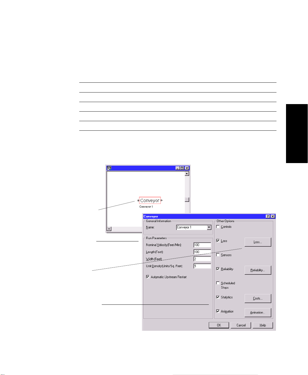
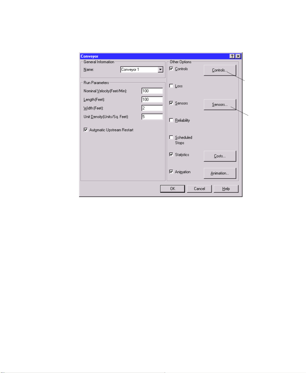
In Arena Packaging, you define equipment parameters such as those listed above by
double-clicking on modules and filling in the descriptive information in the module
dialogs. For example, the main dialog box of the Conveyor module is shown below.
• • • • •
2 • General Concepts
1. Double-click on a
module.
2. Fill in the basic
run parameters.
3. Define loss and
reliability, if
possible.
4. Define basic
animation and/or
desired statistics
for module.
9
Page 16

ARENA PACKAGING TEMPLATE USER’S GUIDE
• • • • •
All module dialogs are self-contained and designed with terminology for high-volume
applications. The graphical “point-and-click” interface allows you to develop models of
sophisticated systems without writing any code. You just answer the questions in the
dialog boxes.
It is also easy to define basic animation and statistics for a module. Arena Packaging
allows you to generate animation and statistics (e.g., production summary, costing, or
state statistics) for modules automatically by clicking on the Animation and Statistics
check boxes. Animation is placed upon exiting the dialog box. It can then be enhanced by
using symbols from Arena’s picture libraries, Arena Symbol Factory, or from other
graphics files such as Clip Art or AutoCAD
To learn more about defining basic behavior for the Arena Packaging template’s modules,
refer to the module descriptions in Chapter 3 or the HSMART examples listed below.
Step 2 • Define Equipment Behavior
HSMART22: Defining Event-Based Loss
HSMART23: Defining Production-Based Loss
HSMART24: Modeling Reliability Using Expected Uptime
HSMART25: Modeling Reliability Using Reliability
HSMART26: Modeling Reliability Using Multiple Failure Streams
Step 3 • Run the model
At this stage, while you’re probably not ready to reach significant conclusions yet with
your model, you do have a complete tool that you can now build on as your project
progresses. It is a good idea to run this first model to verify that your basic logic is
working correctly. Animation is a great tool for verifying model logic. You can also gain
valuable insight on further detail to add and future strategies with which to experiment.
®
.
10
In Arena Packaging, to run a model, you must first place a Simulate module. This module
defines which categories of Packaging module statistics will be collected as well as additional information such as units of measure. Before starting a simulation run, you will want
to specify the simulation project parameters, such as the number of replications, the run
length, and base time units. This is done by choosing the
File
Arena’s
parameters. Then use the
menu. This opens the Run Setup dialog box. Enter the replication and project
Go
command (
Run
menu) to start the simulation run.
Run > Setup
menu option from
Page 17
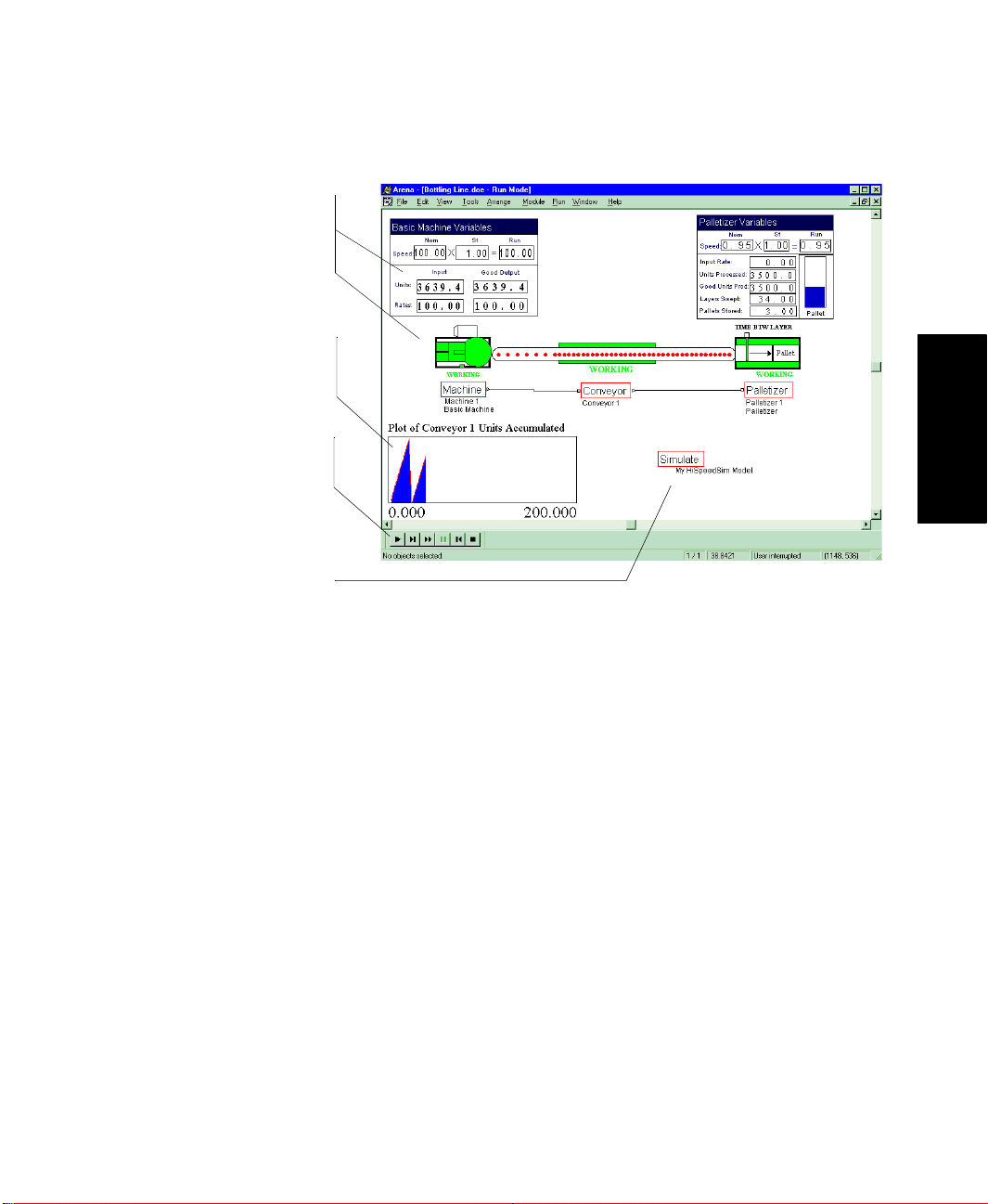
3. Watch Arena Packaging
track variables such as
input and output rates,
throughputs, states,
conveyor accumulations,
etc.
4. Place additional
animation constructs
(e.g., plots) to animate
system variables.
2. Click the Go button on
the Run toolbar to start
the simulation.
1. Place the Simulate
module and specify
advanced options. Enter
replication parameters in
Arena’s Run > Setup
menu.
• • • • •
2 • GENERAL CONCEPTS
2 • General Concepts
When a simulation run begins, Arena Packaging first processes the data and logic of the
system as defined by the modules in the model. Special-purpose variables called Arena
Packaging variables are automatically created for each module. These variables are
dynamic quantities that describe the state of the system. Examples of Arena Packaging
template variables include equipment states, run speeds, input and output rates, throughputs, conveyor accumulation levels, tank levels, etc. A more detailed discussion and list of
the Arena Packaging template variables can be found in Chapter 5 of this user’s guide.
The model of the system is then input into a simulation engine specifically designed for
simulating high-speed, high-volume flow. This engine utilizes two distinct technologies:
SIMAN and an algorithmic kernel. The SIMAN portion of the engine manages discrete
system events such as equipment failures, changeovers, and stops, as well as system
resources such as operators. SIMAN is the core language of the Arena development
environment and has been designed, developed, and successfully used since 1982 to
conduct discrete-event simulations.
11
Page 18
ARENA PACKAGING TEMPLATE USER’S GUIDE
• • • • •
Packaging Edition
Model
Animation
SIMAN Engine
Algorithmic Engine
Statistics
The algorithmic portion of the Arena Packaging
template
’s engine manages the complex
logic and statistics associated with high-speed, high-volume flow. Specifically designed for
simulating high-speed processes, it allows Arena Packaging to simulate the performance of
a high-volume system accurately and efficiently without using entities to represent individual units or batches of units.
As the simulation begins, unit flow starts at the front of lines and moves downstream. The
simulation then automatically tracks, updates, and collects statistics on the Arena
Packaging variables for the length of the simulation run. Numeric values, plots, and levels
of Arena Packaging template variables can be viewed during the simulation using Arena’s
animation constructs.
For more information, refer to the HSMART examples for Step 3.
Step 3 • Run the Model
HSMART28: Updating Arena Packaging Template Variables Automatically
HSMART29: Animating Arena Packaging Template Variables
HSMART31: Custom Pictures for Conveyor Animation
12
Page 19
2 • GENERAL CONCEPTS
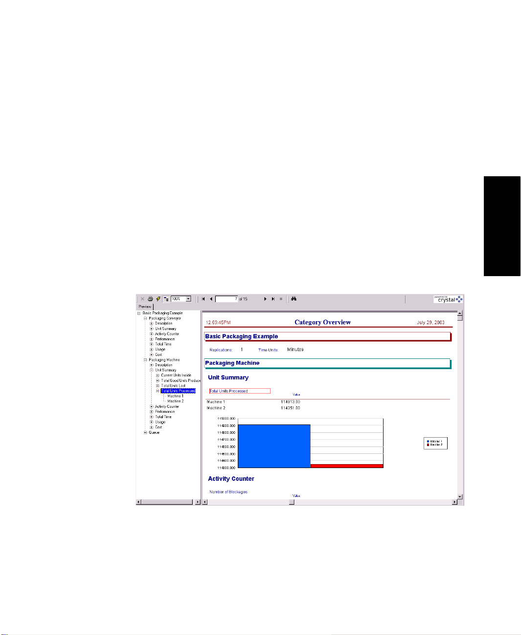
Step 4 • View automatic statistics
A primary objective of most simulation studies is to generate statistics about a system’s
performance so that you can make the “right” decisions.
When an Arena Packaging template model (i.e., .doe file) is run, the simulation results are
stored in a Microsoft Access database (.mdb) file by the same name (e.g., the simulation
results for CandyLine.doe are stored in CandyLine.mdb).
®
Arena Packaging then utilizes Crystal Reports
database. The Category Overview report displays information for system resources
defined using the Packaging template modules, such as machines, palletizers, conveyors,
storages, etc. It also displays information for system resources defined using the Arena
template modules.
Each major section of the report pertains to a type of system resource (e.g., machines,
conveyors, palletizers, storages). Within these sections, statistics are listed by module and
grouped into categories. The categories are Description, Unit Summary, Activity Counter,
Total Time, Cost, Performance, Usage, and Other.
to display the statistics stored in the report
• • • • •
2 • General Concepts
13
Page 20
ARENA PACKAGING TEMPLATE USER’S GUIDE
• • • • •
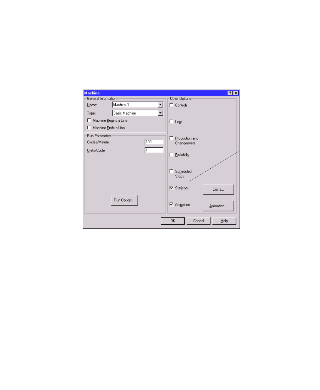
Module statistics are not generated by default. Instead, Arena Packaging allows you to
choose which statistics you want to collect, write to the report database, and see in Crystal
Reports. You specify that a module’s statistics are included in the reports by selecting the
Statistics option in the module dialog box.
Check Statistics to
report statistics for a
module.
14
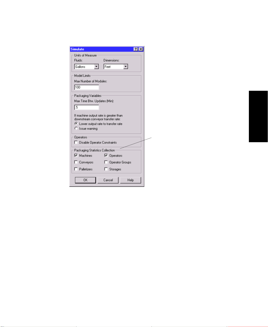
It is also easy to turn off statistics for all modules of a particular type (e.g., turn off
statistics for all conveyors, or all machines). Within the Simulate module, there are check
boxes for collecting statistics on Machines, Conveyors, Palletizers, Operators, Operator
Groups, and Storages. When one of those prompts is checked, statistics will be reported
for all modules of that type that have their individual module-level statistics check box
selected. When one of those prompts is not checked, no modules of that type will have
statistics reported, regardless of whether the individual module-level statistics are
selected.
Page 21
2 • GENERAL CONCEPTS
Turn on/off statistics for all modules of
a particular type in the Simulate
module.
• • • • •
2 • General Concepts
Refer to the HSMART examples for Step 4 for more information.
Step 4 • View Automatic Statistics
HSMART30: Generating Cost Statistics
Step 5 • Experiment with complex strategies
In the first four steps of the methodology, you built a base model of your system’s process;
defined basic equipment behavior such as run speeds, loss, and reliability; and performed
an initial simulation run.
Once that base model and study are completed, you can utilize additional features in
Arena Packaging to experiment with more complex strategies and issues in your line. For
discussion purposes, these strategies and feature sets have been divided into five main
topics.
15
Page 22
ARENA PACKAGING TEMPLATE USER’S GUIDE
• • • • •
The five topics are introduced briefly below.
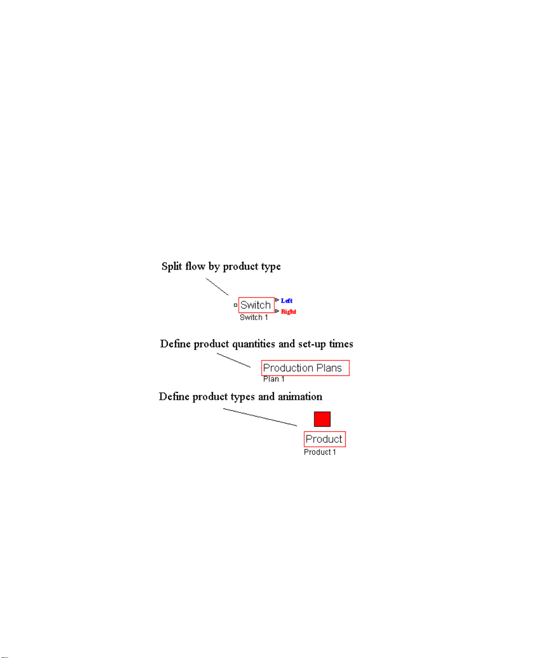
Products, production plans, and changeovers
By default, the Arena Packaging template’s algorithms simulate the flow of a
“generic” or single product type through the system. Optionally, you can model the
flow of multiple product types and thus incorporate product-related issues such as
changeovers, set-up times, product-dependent run speeds, etc.
The Product and Production Plans modules are available for defining multiple products
processed in a system and their requirements. The Production and Changeovers option
in Machine and Palletizer modules is where you assign changeover times or production
plan data to those elements.
The Switch module can be used to split unit flow based on product type.
16
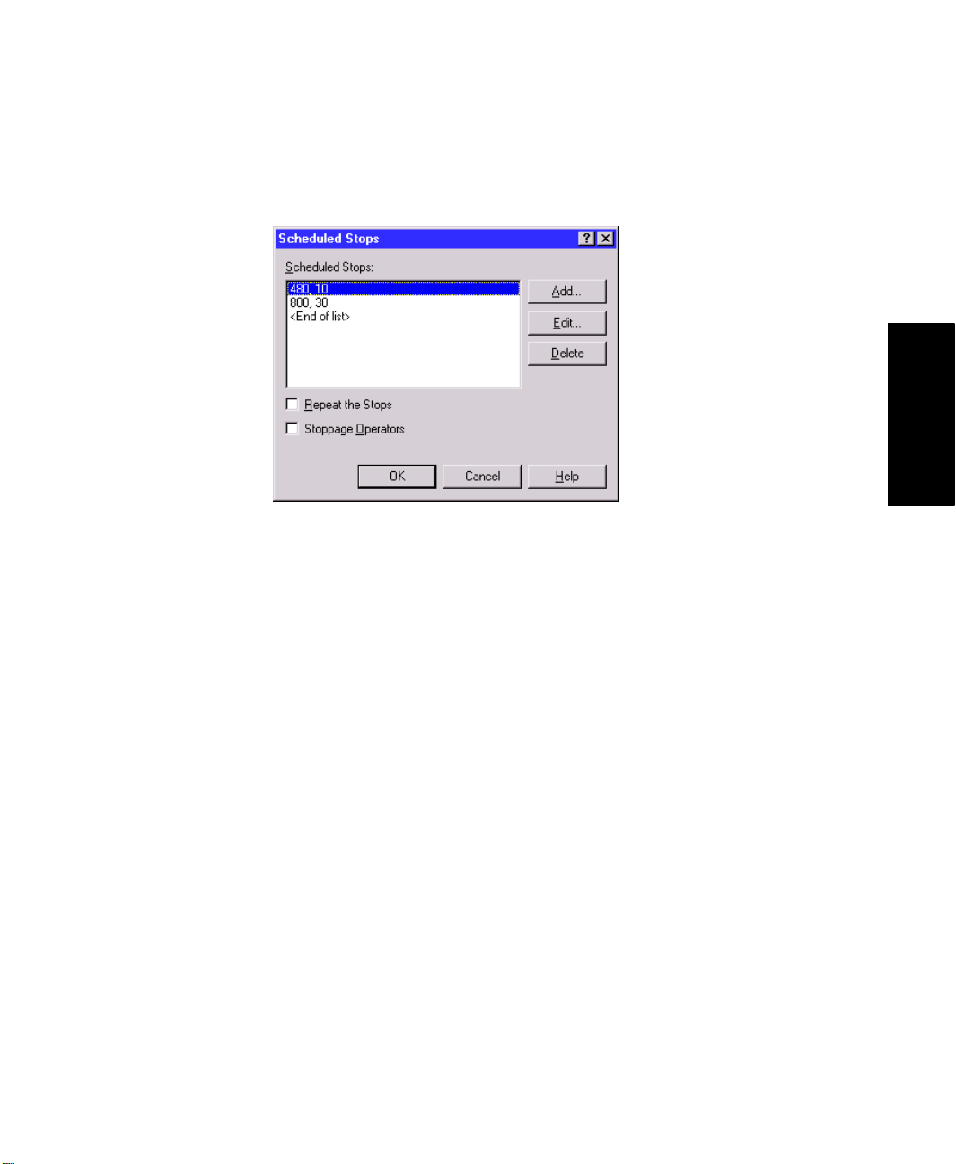
Scheduled stops
Arena Packaging has options for defining scheduled downtimes or maintenance for
machines, conveyors, and palletizers in the system. Scheduled stops are considered to
be planned downtimes and thus are reported and tracked separately from the failures
that occur due to equipment reliability. Unlike failures, scheduled stops are also not
factored into utilization.
Page 23
2 • GENERAL CONCEPTS
The Scheduled Stops option in Machine, Palletizer, and Conveyor modules is where
you define scheduled downtimes for those elements.
Dynamic line control
• • • • •
2 • General Concepts
Dynamic line control is often necessary for regulating or directing particular situations
and events in a system. It can be a critical factor of a line’s design, impacting system
utilization and performance.
The Arena Packaging template has options for placing controls and sensors on equipment such that the details of your functional control system can be incorporated into
the model logic. A control is a function that monitors system status for one or more
conditions. When a condition is true, one or more actions can be taken (e.g., change
the speed factor of a machine). Sensors are devices that can be placed anywhere along
the lengths of conveyors and tanks to monitor accumulation levels of units or fluids.
When a sensor is either covered or uncovered, it is triggered and one or more actions
can be taken.
The Controls option in Machine, Palletizer, and Conveyor modules is where you
define controls for those elements. The Sensors option in Conveyor and Tank modules
is where you define sensors for those elements.
The Actions module is also available for performing actions on the system using
discrete entities and logic rather than controls or sensors.
17
Page 24
ARENA PACKAGING TEMPLATE USER’S GUIDE
• • • • •
Define
controls for
equipment in
the Controls
dialog box.
Place
sensors on
conveyors or
tanks in the
Sensors
dialog box.
18
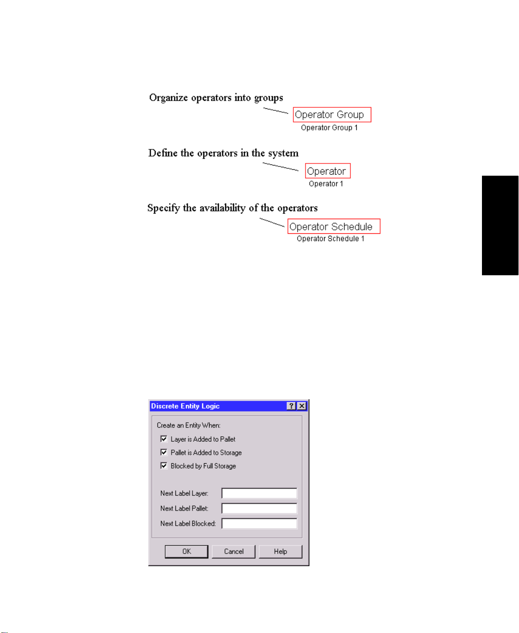
Labor
The availability and training of personnel connected to a high-speed line can be
critical to the line’s success. It can have a direct effect on issues such as utilization,
machine maintenance, and output.
Arena Packaging provides the Operator, Operator Group, and Operator Schedule
modules for modeling the availability and organization of labor in the system. You can
assign operators to failure repairs, scheduled stops, and/or changeover activities in the
equipment modules.
Page 25
2 • GENERAL CONCEPTS
Discrete entity creation and logic
The Arena Packaging template supports the modeling of discrete or “low-speed” logic
in your system. There are several options for creating entities at discrete times during
high-speed simulations, such as when a sensor or control is activated, or when a
palletizer completes a pallet.
• • • • •
2 • General Concepts
The Actions module can also be used to perform actions on the high-speed system (e.g.,
changing run speeds of machines, opening or closing valves, adding pallets to a storage,
etc.) using discrete entities and logic. Therefore, this module facilitates the integration
of discrete logic built with constructs from the general-purpose Arena template.
19
Page 26

ARENA PACKAGING TEMPLATE USER’S GUIDE
• • • • •
Refer to the HSMART examples for Step 5 for illustrations.
Step 5 • Experiment with Complex Strategies
Operators
HSMART32: Modeling Operators and Operator Groups
HSMART33: Modeling Operator Schedules
Control Logic
HSMART34: Adjusting Equipment Speeds Using Controls
HSMART35: Adjusting Equipment Speeds Using Conveyor Sensors
HSMART36: Adjusting Equipment Speeds Using the Actions Module
HSMART37: Writing Detailed Data to Files Using Controls
HSMART38: Writing Detailed Data to Files Using Sensors
HSMART39: Opening and Closing Valves Using Tank Sensors
Products and Changeovers
HSMART40: Using Products and Production Plans (Plan-based Equipment
Changeover)
HSMART41: Modeling Equipment Changeovers (Product-based Equipment
Changeover)
HSMART42: Defining Loss for Changeovers
HSMART43: Product Flow Controls Using the Switch Module
HSMART44: Adjusting Equipment Speeds Based on Product Type
HSMART45: Adjusting Container Volumes at a Filler Based on Product Type
20
Scheduled Stops
HSMART46: Modeling Scheduled Stops
HSMART47: Defining Loss for Scheduled Stops
Integrating with the Arena Template
HSMART48: Creating Discrete Entities
HSMART49: Referencing Arena Packaging Template Variables in Arena
Modules
HSMART50: Modeling the Delivery of Raw Material to an Arena Packaging
Template Line
HSMART51: Modeling Discrete Deliveries of Fluid to a Tank
Page 27

3
The Packaging Panel
Panel modules
This chapter contains a detailed description of each of the Packaging panel modules,
including prompt descriptions and remarks on module usage.
Actions module
D
ESCRIPTION
The Actions module is useful for modeling discrete entity logic that alters the status of the
system, but which is not directly dependent upon equipment sensors or controls. When an
entity enters this module, it performs the set of actions defined in the Actions repeat
group. The Actions module is similar to the Actions dialog box found in the Controls and
Sensors dialog boxes of Machines, Conveyors, and Palletizers. There is no time delay
associated with this module.
R
EMARKS
The Actions dialog boxes found in the Controls and Sensors dialog boxes of Machines,
Conveyors, and Palletizers allow you to alter system status when controls and/or sensors
are activated. The Actions module provides similar functionality as those Actions dialog
boxes in the equipment modules. It provides additional system control by allowing you to
initiate actions using discrete entities.
The Arena Packaging
Packaging modules. These special-purpose variables are automatically defined and
assigned values over the course of a simulation by the Arena Packaging engine. They
reference both dynamic and static information of a modeled system (e.g., equipment run
speeds, input and output rates, conveyor accumulation levels, throughput quantities,
storage and tank levels, etc.).
Use the Update HiSpeedSim Variables action to make sure that all packaging-related
variables reflect the current state before using them. This is especially useful if you will be
making decisions based on variable values, writing them, or using them in calculations.
Note that the action is named “Update HiSpeedSim Variables” rather than “Update
Packaging Variables” to maintain compatibility with models built in earlier versions of the
software.
template
provides a set of Packaging variables for several of the
3 • Packaging Panel
21
Page 28
ARENA PACKAGING TEMPLATE USER’S GUIDE
• • • • •
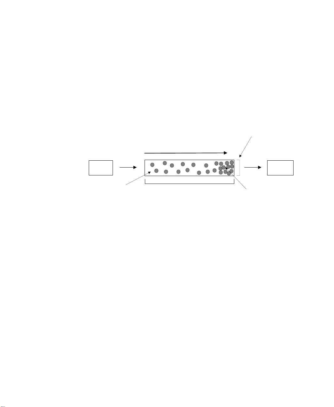
Conveyor module
D
ESCRIPTION
This module defines the accumulating conveyor elements that move product through the
system. Accumulating conveyors allow products to move on the conveyor even if products
at the end of the conveyor are stopped. They are typically used as buffers to level out line
fluctuations caused by machine stoppages, failures, differences in run speeds, etc. The
following figure shows some basic terminology and attributes for accumulating conveyors.
Upstream
Module
Accumulating Conveyor
Velocity (F eet or Meters/ Min
Input Rate
(Units/Min)
Traveling Units
Capacity (Units) = (Length) * (Width) * (Unit Density)
Nominal Run Speed (Units/Min) = (Velocity) * (Width) * (Unit Density)
Length (Feet or Meters)
Width (Feet or Meters)
Output Rate
(Units/Min)
Accumulated Units
of Specified Density
Downstream
Module
Products enter the conveyor from the upstream module and travel along the conveyor’s
length. If the Output Rate off of the conveyor is less than the Input Rate onto the
conveyor, then products accumulate in front of the downstream module.
You can also specify optional characteristics for conveyors such as sensors, controls, loss,
reliability, and scheduled stops.
R
EMARKS
Refer to the Sensors, Controls, Loss, Reliability, Scheduled Stops, Costs, and Animation
dialog boxes for more information on these options.
Accumulating conveyors are always initially active with a speed factor of 1 at the beginning of a simulation run.
22
A conveyor’s run parameters may be specified in either metric or English units of
measure, depending on what is selected for Units of Measure in the Simulate module. See
the “Simulate module” on page 36 for further information.
Conveyor modules may not be linked directly to other Conveyor modules. The Conveyor
Link module must be used to model adjoining conveyors.
Page 29

3 • THE PACKAGING PANEL
To model non-accumulating conveyors, use a Machine module of type Conveyor Machine.
The Split and Merge modules may be used to model splitting product flow across multiple
conveyors or merging the product flow of multiple conveyors onto a single conveyor.
The Switch module may be used to direct flow off a single inbound conveyor onto one of
two possible outbound conveyors (i.e., flow goes “left” or “right”).
Conveyor Link (CLink) module
D
ESCRIPTION
The Conveyor Link module is used to connect two Conveyor modules directly.
R
EMARKS
You may open or close a conveyor link using the Actions dialog box to permit or prohibit
material from passing between conveyors.
• • • • •
Label module
D
ESCRIPTION
The Label module may be used to identify a particular portion of the model logic,
whereby discrete entities may be sent easily to the label from other locations in the model.
The name of a label module can be referenced in a “Send to Label” field (e.g., in a Sensor
dialog box) to send discrete entities to this module. Upon arriving to the Label module,
each entity will immediately proceed to the next module that is graphically connected to
the Label module’s exit point.
Machine module
D
ESCRIPTION
The Machine module defines the processing elements of the system. Four general types of
machines are available for modeling purposes. These types are Basic Machines, Assembly
Machines, Filling Machines, and Conveyor Machines (standard or single-file). Each is
detailed below.
3 • Packaging Panel
23
Page 30
ARENA PACKAGING TEMPLATE USER’S GUIDE
• • • • •
Basic Machines for standard processing. Examples include labeling, inspecting, and
packaging operations that do not involve multiple inbound lines. The nominal run
speed of the machine is defined in terms of cycles/min and units/cycle. Basic
machines do not have capacity; the process is instantaneous and capacity is 0.
Inbound Line Outbound Line
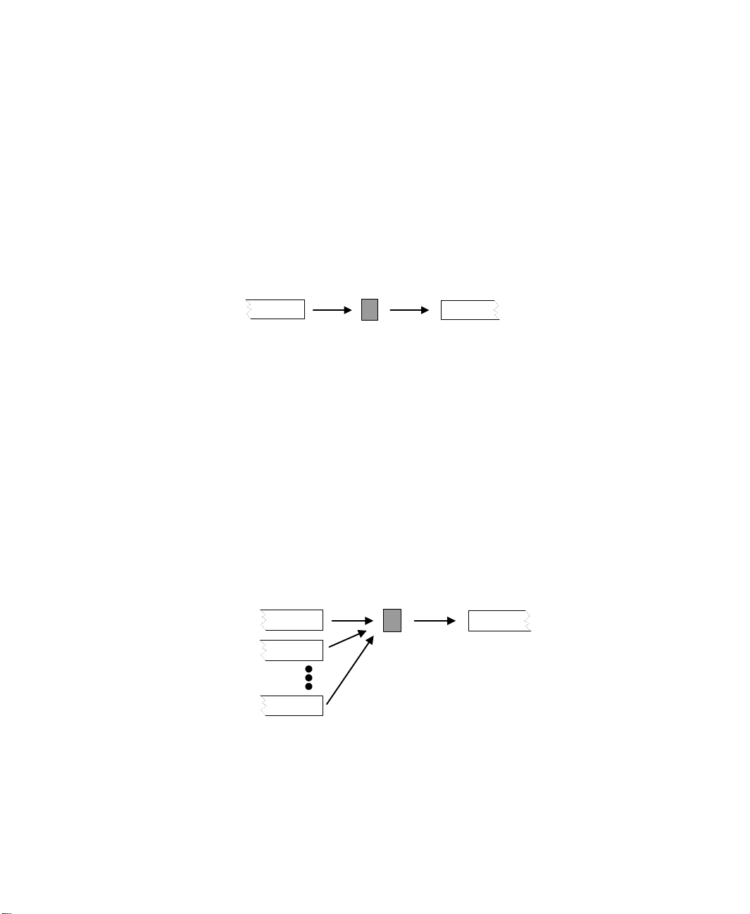
Assembly Machines for merging input from two or more inbound lines (non-fluid).
Examples include capping and packaging operations. The nominal run speed of the
machine is defined in terms of cycles/min and assemblies/cycle. In addition to the run
speed of the assembly operation, output rates from the inbound lines are dependent on
the units/assembly required from each line.
A single inbound line can also be defined for an assembly machine to model a batching operation (e.g., shrink-wrapping inbound units). Assembly machines do not have
capacity; the process is instantaneous and capacity is 0.
Basic Machine
Nominal Run Speed
Cycles/Minute
Units/Cycle
24
Assembly Machine
Nominal Run Speed
Cycles/Minute
Inbound Line Outbound Line
Units/Assembly
Assemblies/Cycle
Page 31

3 • THE PACKAGING PANEL
Filling Machines for specifically merging an inbound fluid line (i.e., a tank module)
with an inbound container line. The nominal run speed of the machine is defined in
terms of cycles/minute and containers/cycle. To model product movement during the
filling operation, a Machine Capacity may be specified. The volumes of the containers
can be constant (Fixed) or vary by product type (Variable).
Filling Machine
Nominal Run Speed
Inbound Line
Fluid
Containers
Cycles/Minute
Containers/Cycle
Outbound Line
Capacity
Fixed or Variable
Container Volumes
• • • • •
3 • Packaging Panel
Conveyor Machines are useful for modeling processes that involve significant
product movement on a non-accumulating conveyor. Examples include washing and
drying operations. You may specify the run parameters of the conveyor in two ways. If
the units on the conveyor always travel in single file, then you may specify the
machine Type as “Conveyor Machine (Single File)” and directly specify the nominal
run speed of the machine and its capacity (i.e., max length of the single file). Or,
specify the machine Type as simply “Conveyor Machine” and enter the nominal
velocity, length, width, and unit density parameters for the conveyor.
25
Page 32

ARENA PACKAGING TEMPLATE USER’S GUIDE
• • • • •
See the diagrams below for further illustration of the Conveyor Machine run
parameters.
Conveyor Machine
(Non-Accumulating Conveyor)
Nominal Velocity (Units/Min)
Inbound Line
Traveling Units at
Inbound Line
Unit Density
Units/Minute
Length (Feet or Meters)
or (Single File)
Nominal Velocity (Units/Min)
Units/Minute
Capacity (max # units on
the conveyor in single file
Outbound Line
Width (Feet or
Meters
Outbound Line
For all the machine types in this module, optional characteristics such as loss, scheduled
stops, changeovers, reliability, and controls may be defined.
R
EMARKS
All of the machine types have the same dialog boxes for Run Options, Controls, Loss,
Production and Changeovers, Reliability, Scheduled Stops, Costs, and Animation. Refer
to these dialog boxes for more information.
The nominal run speed is usually thought of as the maximum speed at which the machine
can maintain a consistent production of quality units.
26
The module connected to the input line(s) of a Basic, Assembly, or Conveyor Machine
must be a Conveyor or Machine Link module. See the “Filling Machines” notes below
regarding connecting modules to the inputs of a Filling Machine.
The module connected to the output line of any Machine module must be a Conveyor or
Machine Link module.
Page 33

3 • THE PACKAGING PANEL
Machine modules may not be directly linked to other machine modules. Use a Machine
Link module to connect two machines directly together (i.e., there is a negligible accumulator between the machines).
• • • • •
Assembly Machines.
A maximum of 10 entry lines may be specified for the Assembly
Machine type. Note that the first entry line always defines the outbound product name.
For example, if units from the first entry line have the product name “bottles,” and units
from the second entry line have the product name “caps,” the product name for the
assembled units is “bottles.”
Filling Machines.
For Filling Machines, the container input line always defines the
outbound product name.
The module connected to the fluid input line of a Filling Machine must be a Tank module
from either the Packaging or Flow Process panel. The Flow Process Tank module is
recommended when modeling advanced tank-related logic such as semi-continuous batch
processes feeding a high-speed packaging line.
The module connected to the container input line of a Filling Machine must be a
Conveyor or Machine Link module.
If using a filling machine, note that all volumetric data in the model, such as tank capacities, valve maximum rates, and container volumes, must be specified in the same units of
measure (e.g., gallons, liters, fluid ounces, etc.).
Conveyor Machines.
A Conveyor Machine is a non-accumulating conveyor. You may
specify the run parameters of the conveyor in two ways. If the units on the conveyor
always travel in single file, then you may specify the machine Type as “Conveyor
Machine (Single File)” and directly specify the nominal run speed of the machine and its
capacity. Or, specify the machine Type as simply “Conveyor Machine” and enter the
velocity, length, width, and unit density parameters for the conveyor.
3 • Packaging Panel
Machine Link (MLink) module
D
ESCRIPTION
The Machine Link (ML) module may be used to connect two Machine modules directly.
Use this module if there is no buffer between the machines. If accumulation can occur
between the machines, then use the Conveyor module to model the accumulator.
A Machine Link module may only be connected to Machine modules. If your logic requires
that two non-Machine modules be connected without a buffer in between, then use a
Conveyor module. Define the Nominal Velocity to a high rate (e.g., 100,000 feet/min) and
the Length, Width, and Unit Density so the conveyor capacity is 1 unit. This approach
models a negligible buffer.
27
Page 34

ARENA PACKAGING TEMPLATE USER’S GUIDE
• • • • •
Merge module
D
ESCRIPTION
The Merge module merges two or more incoming streams from accumulating conveyors
into a single outgoing stream. A product name may be assigned to the outgoing stream.
R
EMARKS
Only Conveyor modules can be connected to a Merge module. There is no limit on the
number of incoming conveyors that may be connected to the input of the merge.
If the downstream conveyor cannot accept all of the flow from the upstream conveyors,
each will be adjusted proportionally. Proportions are recalculated any time any flow rate
of any of the conveyors change.
For example, if three conveyors (A, B, and C) each capable of producing 100 units/minute
were merged onto a single conveyor with a flow rate of 150 units/minute, then A, B, and C
would each have a flow rate of (100 * (150/(100+100+100)) = 50 units/minute. If at a later
time, the flow of conveyor A were to stop (perhaps it is starved), then B and C will each be
adjusted to a flow rate of (100 * (150/(100+100)) = 75 units/minute.
Operator module
28
D
ESCRIPTION
The Operator module defines an operator that may be allocated to activities in the system.
Activities include device changeovers (specified in Production and Changeovers dialogs),
device repairs (specified in Reliability dialogs), and scheduled stops of devices (specified
in Scheduled Stops dialogs).
R
EMARKS
If a schedule name is specified for an operator, that schedule should be defined using the
Operator Schedule module.
The Operators module may be used in conjunction with the Operator Group module to
define a set of operators that may be referenced with a common name. For example, the
operators Bill, Mary, and Joe may be grouped into a set of operators named Mechanics.
There are three automatic operator states for operators: On-Duty Idle, Working (or UserDefined), and Off-Duty. An operator is in the state On-Duty Idle whenever the operator is
not busy, but it is on-shift. Upon being allocated to an activity, an operator is automatically assigned the state Wo rk in g. The Wo rk in g state may be replaced with a user-defined
state for any activity through a Machine, Conveyor, or Palletizer Operator dialog box (for
the specific activity).
Page 35

3 • THE PACKAGING PANEL
The state Off-Duty is automatically assigned to an operator when the operator follows an
Operator Schedule and that schedule has the operator unavailable. This includes any
Break and Lunch periods specified by the schedule.
If cost statistics are used, operators accrue cost whenever they are available, busy, or in a
lunch or break.
If an operator follows an Operator Schedule and is scheduled for either Off-Duty, Lunch,
or Break at a specific time, the task will be suspended immediately. The task will wait
until the specific operator (or another operator from the group if a group was specified)
becomes available. At that point, the task will resume with the remaining time adjusted by
the appropriate labor skill factors.
Statistics may be obtained and displayed for operator states by checking the Statistics
toggle. Refer to the Statistic dialog box for more information.
The following table summarizes how the states relate to each other, when they are entered,
and the costing considerations.
• • • • •
Operator State When Assigned Cost Applied?
Working or User-Defined Upon allocation to any activity Yes
On-Duty Idle When the operator is scheduled, but not
busy
Off-Duty (including Lunch
and Break)
When operator is unavailable due to the
Operator Schedule
Ye s
Yes–Lunch and Break
No–Otherwise
Activities that may require operators include changeovers (specified in Production and
Changeovers dialog boxes), failure repairs (specified in Reliability dialog boxes), and
scheduled stops (specified in Scheduled Stops dialog boxes). Refer to these dialog boxes
and the Operators dialog box for information on specifying operator requirements.
Operator Group module
D
ESCRIPTION
The Operator Group module may be used in conjunction with the Operator module to
define a group of operators that may be referenced with a common name. For example,
the operators Bill, Tom, and Joe may be grouped into a set of operators named Mechanics.
Statistics for the operator group may be collected and reported by checking the Statistics
option.
3 • Packaging Panel
29
Page 36

ARENA PACKAGING TEMPLATE USER’S GUIDE
• • • • •
R
EMARKS
If an operator is selected for an activity from an operator set, the skill factor of that operator as defined in the Operator Group module will be used for that operator for that activity.
A common use of Operator Groups is to form a group of people who can perform certain
tasks. For example, you might have an Electricians group and a Mechanics group. Some
tasks might require just an Electrician, some tasks might require just a Mechanic, and
some tasks might require multiple Electricians and Mechanics.
Another common use is to create groups of primary and alternate people. For example,
you might form a group called Repairmen that consists of Journeyman, Apprentice, and
Supervisor (in that order). Then when you specify that an activity needs someone from the
Repairmen group, you can specify Preferred Order for the selection rule. This will select
Journeyman (if available); otherwise, Apprentice (if available); otherwise, Supervisor. If
none are available, it will wait for the first of the three that becomes available.
Operator Schedule module
D
ESCRIPTION
The Operator Schedule module defines schedules to which operators (individual or
groups) can be assigned. The schedule is based on the planning horizon structure, with an
operator availability state associated with each timeslot. A timeslot is the smallest time
period that can be scheduled (e.g., 15 min., 30 min., or 1 hour).
30
The defined availability states include On-Duty, Lunch, and Break. If a shift does not
define one of these states for any period of time, the operator is presumed to be Off-Duty.
R
EMARKS
By default, all timeslots are initialized to an Off-Duty availability state. Therefore,
operator shifts need only be defined for those time intervals that are not Off-Duty.
The starting and ending times for shifts must coincide with the starting and ending times
of timeslots within the planning horizon.
Overlapping operator shift intervals are not allowed. For example, a shift from 8:00
PM and a shift from 2:00 PM to 5:00 PM on the same day is invalid.
3:00
AM to
Shifts are defined for each calendar day. Therefore, a shift that spans two days must be
defined in two separate segments (e.g., Monday: 8:00
AM).
6:00
PM – midnight; Tuesday: midnight –
An entry must be made in the Daily Schedule for each day of the week, although no shifts
need to be defined for any day. For example, if everyone is Off-Duty on the weekends, no
Page 37

3 • THE PACKAGING PANEL
shifts need to be defined for Saturday and Sunday, although Saturday and Sunday must
appear in the Daily Schedule list.
The beginning of the simulation (time 0.0) is midnight before the first day. If days are
specified, the first day simulated will be Monday.
If costing is being applied to operators, costs are assigned only to Working (UserDefined), Lunch, On-Duty Idle, and Break times.
Palletizer module
D
ESCRIPTION
Palletizers model the physical ends of a line where units are stored onto or removed from
pallets. Each module defines either a palletizing or depalletizing piece of equipment.
Palletizers are one of the possible interfaces to the discrete world. A palletizer turns
individual units from a high-speed process into discrete pallets. A depalletizer turns
discrete pallets into units for high-speed processing.
A depalletizer is located at the front of a high-speed line. It removes pallets from storage
and then sweeps units off the pallets onto the downstream conveyor. A palletizer is
located at the end of a high-speed line. It sweeps units off the upstream conveyor onto
pallets, and then places the pallets into storage.
• • • • •
3 • Packaging Panel
It is important to note that Machine modules may also be used to model basic sources or
sinks of a processing line. Machine modules are more efficient than Palletizer modules
with regard to model execution speed. Therefore, if an end element can be modeled as a
simple “rate-in” or “rate-out” process with reliability, scheduled stop, or changeover
constraints, the Machine module is recommended.
Palletizer modules are most useful when:
Discrete batching of units onto or off of the line is a key issue in your problem solving.
The Palletizer module easily allows you to discretize high-speed, high-volume flow
into layers and pallets. Discrete entities representing these layers or pallets can be
received from or sent to “low-speed” portions of your modeled system.
You have supply or storage constraints in your model. In conjunction with the Storage
module, the Palletizer module allows you to model the starvation of depalletizing
equipment at the front of a high-speed line due to inadequate supplies of raw material.
Similarly, you can model the blockages of palletizing equipment at the end of a highspeed line due to inadequate storage space for finished product.
31
Page 38

ARENA PACKAGING TEMPLATE USER’S GUIDE
• • • • •
R
EMARKS
Palletizers and depalletizers are always connected to Conveyor modules.
If the Palletizer Type is Palletizer, then units accumulate in front of the Palletizer and are
removed at a maximum rate of approximately (Units/Layer)*(Nom. Run Speed) units/min
(assuming speed factor of 1) off the conveyor and stored in the storage area (a pallet at a
time) until the maximum capacity of the storage area is reached.
Run parameters include the number of units per layer and the number of layers per pallet.
The Time Between Layers is the setup time before the next layer can be filled, and the
Time Between Pallets is the setup time before the first layer of a pallet can be filled. The
palletizer cannot remove units from the upstream conveyor during these delays. Note that
filling, time between layers, and time between pallet operations are halted if the speed
factor of the palletizer is set to zero (e.g., due to a failure, scheduled stop, or changeover).
There is no module exit label if the Palletizer Type is Palletizer unless one or more
discrete entity options are enabled.
A Palletizer may be initially active or inactive, depending on what is specified in the Run
Options dialog box.
Storage capacity is assumed to be infinite unless a Storage module specifies a limit.
If the Palletizer Type is Depalletizer, then units are introduced from the Palletizer into the
accumulation conveyor (or Machine Link) at the rate of approximately (Units/Layer) *
(Nom. Run Speed) units/min (assuming speed factor of 1), unless the Palletizer is shut
down or there is no inventory in the storage area. The run parameters of the Depalletizer
are similar to the Palletizer, with the difference being that units are getting introduced
back into the system from storage rather than being removed.
32
There is no module entry label if the Palletizer Type is Depalletizer.
A Depalletizer initially may be active or inactive, depending on what is specified in the
Run Options dialog box.
The inventory in Storage Name may also be incremented or decremented (by pallets)
independent of the palletizer’s operation via the Actions dialog box or Actions module.
Refer to the Actions dialog box description for more information.
Refer to the Controls, Loss, Reliability, Run Options, and Scheduled Stops dialog boxes
for more information on these options.
Both types of palletizers interface between discrete operations and non-discrete, highspeed unit flow. Because each discrete operation causes system updates, use of a palletizer
with many discrete operations can slow the execution speed of the entire model. Often the
internal workings of a palletizer are not important to the system being modeled. If this is
the case, model execution speed can be improved dramatically by reducing the discrete
Page 39

3 • THE PACKAGING PANEL
interactions to the minimum level. One way of doing this is to assume (for modeling
purposes) that there is only one layer per pallet. Then set Units/Layer to the total number
of units on a pallet, Time Between Layers to 0.0, and Layers/Pallet to 1.0. Of course, if the
internal workings of the palletizer are important, then you should use all the available
options to model it accurately.
P
ALLETIZER LOGIC
The following diagram and discussion illustrate the detailed internal workings of a
palletizer.
Palletizer Logic
Fi ll Layer at
Run S peed (Layers/M in)
Conveyor
Pallet Storage
Layers/
Pallet
Capaci ty
• • • • •
Yes
Storag e Not Ful l
Time Betw.
Pallets
Add Pallet;
Create En tity
Time Betw.
Pallets
Fil l
Layer
Add Layer;
Create En tity
Time Betw.
Layers
Time Betw.
Layers
Pallet
Ful l?
No
Yes No
Storage
Full?
Create En tity
Blocked
First, the palletizer takes units off the upstream conveyor at its run speed and fills a layer.
The run speed of the palletizer is calculated as follows:
Run Speed (layers/min) = Nom. Run Speed (layers/min) * Sf
or
Run Speed (units/min) = Nom. Run Speed (layers/min) * Sf * Units/Layer.
S
is the speed factor of the palletizer. The speed factor can be dynamically assigned
f
values using the Change Speed Factor of Palletizer action. Nom. Run Speed and
Units/Layer are defined in the Run Parameters section of the Palletizer main dialog box.
3 • Packaging Panel
33
Page 40

ARENA PACKAGING TEMPLATE USER’S GUIDE
• • • • •
As an example, suppose a palletizer has a Nom. Run Speed of 3 layers per minute and the
Units/Layer is 150. Assume the speed factor of the palletizer is 1. When filling a layer, the
palletizer takes units off the conveyor at a rate of 450 units per minute (i.e., 3 layers/min *
150 units/layer). Therefore, if enough units are available on the conveyor, it takes 20
seconds to fill a layer.
After a layer is filled, the palletizer can delay for a specified amount of time (i.e., the Time
Between Layers). Normally, this period represents the time required to sweep the layer of
units onto the pallet. It can also represent any other type of time required before the next
layer is filled.
The Time Between Layers is defined in the Run Parameters section of the Palletizer main
dialog box. It can be a constant or sampled from a random distribution. Note that the input
rate of the palletizer is zero during the Time Between Layers. A palletizer only accepts
units from the upstream conveyor when it is filling a layer.
After Time Between Layers, the palletizer checks whether the pallet is full. The Layers/
Pallet parameter defines the pallet size. If the number of layers on the pallet is fewer than
Layers/Pallet, then the palletizer starts filling another layer. If the number of layers on the
pallet is equal to Layers/Pallet (i.e., the pallet is full), then the palletizer tries to place the
completed pallet into storage.
The Storage Name operand in General Information specifies the location where pallets are
stored. This operand may or may not reference the name of a Storage module. If Storage
Name does not reference a Storage module, the palletizer assumes an infinite pallet
capacity for the storage. In this case, the pallet is automatically added to the storage. The
palletizer can also create a discrete entity when a pallet is added.
34
If Storage Name does reference a Storage module, then the palletizer must check whether
the storage is full before adding the pallet. Storage modules have a pallet capacity. If the
storage is full, then the palletizer cannot add the pallet and it is blocked. It remains
blocked until space is available in the storage. Note that in Discrete Entity Logic you can
create a discrete entity when a palletizer is blocked.
After a pallet is stored, the palletizer can delay for a specified amount of time (i.e., the
Time Between Pallets). Normally, this period represents the time required to store the pallet
and then setup the next one. It can also represent any other type of time required before the
first layer of the next pallet is filled.
The Time Between Pallets is defined in the Run Parameters section of the Palletizer main
dialog box. It can be a constant or sampled from a random distribution. Note that the input
rate of the palletizer is still zero during the Time Between Pallets. A palletizer only
accepts units from the upstream conveyor when it is filling a layer.
Page 41

3 • THE PACKAGING PANEL
D
EPALLETIZER LOGIC
The figure below illustrates the basic operating behavior and characteristics of a
depalletizer:
Depalletizer Logic
• • • • •
Capacity
Storage
Empty?
Yes
Create Entity
Starved
Storage
Time B etw.
Pallets
No
Remove Pallet;
Create Entity
Storag e Not Empty
Layers/
Pallet
Ti m e B etw.
Pallets
Pallet
Time Betw.
Layers
Empty
Layer
Empty Layer at
Run S peed (Layers/M in)
Remove Layer;
Create Entity
Conveyor
Ti m e B etw.
Layers
Pallet
Empty?
No
Yes
The operation is parallel to the operation discussed previously for palletizers.
Product module
D
ESCRIPTION
The Product module defines the name of a product being produced in the system. Product
names may be referenced for changeovers, switches, production plans, and may be assigned
to product names in a model. Example names include “candy bars,” “demo boxes,”
“packaging,” “16 ounce,” “32 ounce,” etc.
3 • Packaging Panel
R
EMARKS
Product names entered into this module are placed onto a product name drop-down list.
If product names are not defined or referenced in the model, the Arena Packaging template
assumes a single generic product is being produced. Thus, Product and Production Plans
modules are not required in a model. These modules are useful if different products are
being processed in the system and there is product-dependent logic (e.g., changeovers or
product-dependent run-speeds, etc.). You must place one Product module for each product
referenced in your model.
35
Page 42

ARENA PACKAGING TEMPLATE USER’S GUIDE
• • • • •
If you double-click on the default product animation (a red box), you can replace or
customize it to display your own product.
Production Plans module
D
ESCRIPTION
The Production Plans module defines the parameters for production plans. These plans
may be referenced and implemented by machines via the Production and Changeovers
dialog box.
R
EMARKS
If a machine is using a product plan, then the plan is executed as follows:
1. Incur the setup time.
2. Produce quantity of product name.
3. Go to next step in plan.
When all the steps of a plan are finished, the process automatically loops back to the first
step in the plan until the simulation run is complete.
During the setup time, the state of the equipment is set to Changeover.
Refer to the Production and Changeovers dialog box for more information on how a
machine implements a production plan.
36
Simulate module
D
ESCRIPTION
The Simulate module defines advanced run options for a simulation experiment such as
units of measure, model limits, and statistics collection.
This is a required module.
R
EMARKS
In previous versions of this software, the Simulate module also defined project and run
parameters such as analyst name, project title, number of replications, and replication
length. That information is now defined in Arena’s Run > Setup tab.
The Module Array Size fixes the maximum number of devices you can place in a model.
This number may have to be increased for large models.
Page 43

3 • THE PACKAGING PANEL
Split module
D
ESCRIPTION
The Split module splits a single incoming product stream into two or more outgoing
streams. Percentages are used to determine the outbound flow proportions. Outbound
product names may also be assigned.
R
EMARKS
The sum of all the specified percentages must equal 100% or a run-time error will result.
A Fixed Split will always divide the product with the exact percentages you have
specified. It will not maximize flow, but rather, will reduce the output of all branches as
necessary to maintain the specified percentages. For example, assume you have two
incoming conveyors with maximum flows of 100 and 200, and an outbound conveyor
with maximum flow of 300. If you specify a 40%/60% fixed split, then the output of the
second conveyor would be limited to ((60/40) * 100) = 150. If any outbound conveyor
cannot accept product (perhaps due to accumulation or equipment failure), then all output
from the Split will be turned off.
An Adjustable Split will automatically adjust the output of each branch to maximize flow.
It will account for any constraints while attempting to achieve the designated percentages.
For example, if you have three conveyors each designated at 33.33% and one conveyor is
stopped, then the other two conveyors will each get 50% of the flow. A special case of the
Adjustable Split is available if you specify 100% for one line and 0% for every other
output. This is useful for modeling primary and secondary flow (such as a surge table or
backup line) where the secondary line is only used when the primary line is unable to take
the full Split output.
• • • • •
3 • Packaging Panel
Storage module
D
ESCRIPTION
The Storage module allows you to specify the parameters of a storage area as well as
animation and statistics. The Storage module is used in conjunction with the Palletizer
module. If a Storage module is not placed, then the default storage area has infinite
capacity and no animation.
R
EMARKS
In many cases, the storage is not a significant part of the model. If an infinite capacity
storage with no statistics or animation is acceptable, then no Storage module is necessary.
One way to keep a depalletizer’s storage replenished is to create an entity every time it
becomes empty, then make a connection from the Storage is Empty connection point to
37
Page 44

ARENA PACKAGING TEMPLATE USER’S GUIDE
• • • • •
the discrete logic that represents the activities necessary to replenish the storage (for
example, a Server module). Then that entity could connect to the Add a Pallet connection
point. If you wanted to add several pallets at a time, instead of using the Add a Pallet
connection, you would connect to an Actions module and specify the Add Pallets to
Storage action.
Likewise, you can use discrete logic to keep a Palletizer’s storage full. Simply create an
entity every time it becomes full, then make a connection from the Storage is Full connection point to the discrete logic that represents the activities necessary to empty the storage
(for example a Process module). Then that entity could connect to the Remove a Pallet
connection point. If you wanted to remove several pallets at a time, then instead of using
the Remove a Pallet connection, you would connect to an Actions module and specify the
Remove Pallets from Storage action.
Refer to the Discrete Entity Logic dialog box in the Palletizer module for other related
options for creating discrete entities.
Switch module
D
ESCRIPTION
The Switch module may be used to regulate the flow of a single incoming stream into two
outgoing streams (a “left” stream and “right” stream). The flow can be regulated either by
product waves, by discrete action, or by unit counts. There may be a delay time associated
with the switch.
38
R
EMARKS
If Switch On Product Name is specified, any unlisted product name that comes through
the switch will always go to the left branch.
If the switch Type is Action, then a “Change Direction of Switch” action in an Actions
dialog box or the Actions module may be used to alter the direction of the switch.
Tank module
D
ESCRIPTION
The Tank module may be used to represent a container or holding area for any fluid-like
material. It is typically used in combination with one or more valves and a filling
machine.
Page 45

R
EMARKS
Tanks may only be connected directly to valves or a filling machine. A common configuration is to have a valve controlling flow into a tank, which is in turn connected to a filling
machine.
Units of measure for the fluid volumes may be specified in the Simulate module.
Valve module
D
ESCRIPTION
The Valve module regulates the flow of fluids into or out of a tank, or between two tanks.
R
EMARKS
You can open or close a valve using an “Open Valve” or “Close Valve” action in an
Actions dialog box or the Actions module. Units of measure for fluid volumes may be
specified in the Simulate module.
Common module dialogs
• • • • •
3 • THE PACKAGING PANEL
3 • Packaging Panel
Many of the Packaging modules have similar sections in the module dialog box user
interface. For example, the Machine, Conveyor, and Palletizer modules all include the
Reliability dialog box, where you can define the reliability characteristics of the
equipment.
We’ll now detail these common module dialog boxes.
Actions dialog
D
ESCRIPTION
The Actions dialog box allows you to specify one or more actions to take that will
influence the system operation. The Actions dialog box is found in the Controls and
Sensors dialog boxes of Machines, Conveyors, and Palletizers, as well as in the Actions
module. The action is activated by the appropriate sensor or control being activated, or by
an entity entering the Actions module.
39
Page 46

ARENA PACKAGING TEMPLATE USER’S GUIDE
• • • • •
Animation dialog
D
ESCRIPTION
The Animation dialog box appears in most constructs to provide on-screen indicators of
model operation as the simulation executes. Depending on the construct, different options
are available. Possible options include a state indicator, blocked/starved symbols, a
product picture, and a variables table. In some cases, a module will have an Animation
check box without an Animation button/dialog box. This indicates that there is only one
type of animation available, and it is enabled/disabled using the Animation check box.
R
EMARKS
Product symbols must be defined using Product modules before they can be animated
with the Product Picture option.
Double-clicking on State Indicators and Product Pictures (Product module) allows you to
customize their appearance.
Note that the rate variables displayed in a variables table are always the base time units
variables and thus may show different numbers than what is entered as the “per minute”
run speed in the module dialog boxes. For example, you might define the nominal run
speed of a machine as 100 units per minute in the module dialog box. However, since the
variable Name_BaseNomRunSpeed is what is animated in the machine’s variables table,
if the base time units in Arena’s Run > Setup > Replication Parameters is specified as
“Hours,” then the animation will display a nominal run speed of “6000” (60 minutes * 100
units per minute) at run-time.
40
The pictures used to animate traveling and accumulated units on conveyors (or conveyor
machines) may be customized. By default, the distributed fill level animation shows green
disks for traveling units and red disks for accumulated units. You can replace those default
disk pictures with customized pictures by enabling the Use Picture option in the Level
dialog box. HSMART31 illustrates this feature.
Note that additional animation, such as plots, histograms, and variables, is available from
the Animate toolbar.
Controls dialog
D
ESCRIPTION
The Controls dialog box defines controls for machines (all types), accumulating conveyors,
and palletizers. This dialog box specifies when the controls are evaluated, the conditions
for each control that is evaluated, and the set of actions taken when all the conditions of a
control are true. Multiple controls may be defined for a single machine, conveyor, or
palletizer.
Page 47

3 • THE PACKAGING PANEL
R
EMARKS
Controls are evaluated at discrete times, NOT continously. By default, control conditions
are evaluated every time the status of the equipment changes. You can also specify that
control conditions are evaluated every X time units or X units processed or conveyed.
More frequent evaluations may make the control more accurate, but also may slow the
execution speed of the model. We suggest that you use the check boxes to target evaluation
as closely as possible to obtain the accuracy needed without having unnecessary evaluations
performed.
A control is activated whenever it is evaluated and becomes true. It is only activated when
it changes from false to true. If it stays true across several evaluations, it will only be
activated once. It will not be activated again until it first changes to false for at least one
evaluation and then back to true again.
Within a single Control, all of the conditions must be true in order to activate the control.
In other words, all of the conditions are ANDed together. If you want more complex
conditions or conditions that are connected by OR, you may use the Other Condition
parameter. This provides additional flexibility for more advanced users to specify any
valid conditions.
• • • • •
3 • Packaging Panel
Costs dialog
D
ESCRIPTION
The Costs dialog box defines cost rates for calculating the total cost of a piece of equipment or operator accrued during the simulation run. This dialog box is not applicable if
the module’s Statistics option has not been selected.
R
EMARKS
For a description of the statistics reported for each type of module, refer to Chapter 4,
“Statistics.”
Loss dialog
D
ESCRIPTION
The Loss dialog box allows you to specify the amount of product that is lost (waste)
during device operation. This lost product will show up in the production statistics and the
yield statistics. Loss can be specified in two different categories. Event-Based Loss only
occurs when a specific event occurs. Production-Based Loss occurs whenever the device
is producing product.
41
Page 48

ARENA PACKAGING TEMPLATE USER’S GUIDE
• • • • •
R
EMARKS
The Lost Production percentage can be changed dynamically using a Change Lost
Production of Equipment action.
Operators dialog
D
ESCRIPTION
The Operators dialog box defines the operators required for the processing and delay of a
particular activity. These activities include changeovers (specified in Production and
Changeovers dialogs), failures (specified in Reliability dialogs), and scheduled stops
(specified in Scheduled Stops dialogs). An activity does not begin until all operators are
available simultaneously. Priorities may be given to separate activities using the Priority
field.
The operators for a given activity may include individual operators or members from
operator sets.
R
EMARKS
Individual operators are defined in the Operators module, and operator groups are defined
in the Operator Groups module.
42
The Operators repeat group determines the operators required for the processing and
delay of the activity. All operators must be available and allocated simultaneously for the
activity to begin. After the delay time of the activity, the operators are automatically
released.
When an operator becomes available, the Priority field for an activity determines the
activity to which the operator will be allocated if more than one activity is waiting for the
operator. Activities with lower-value priorities are serviced before activities with highervalue priorities. If multiple activities with equal priorities request the same operator, the
activity with the longest waiting time is allocated the operator. The Priority applies to all
operators listed in the Operators repeat group.
For example, suppose there is a failure at Machine 1 with a priority of 1, and a failure at
Machine 2 with a priority of 2. If both failures require the same operator, and the operator
is currently busy, the operator will be allocated to the failure at Machine 1 when the
operator becomes available.
After an operator is allocated to the activity, it is assigned the Operator State specified.
The default state is Working, but may be changed to reflect either the type of activity (i.e.,
Working on Failures) or the machine/equipment (i.e., Working at Machine 1).
Page 49

3 • THE PACKAGING PANEL
The Operator State is assigned to all operators listed in the Operators repeat group. Refer
to the “Operator module” on page 28 for more information on operator states.
Skill factors for operators are defined in the Operator module. If the Skill Adjustment
check box is checked, then the inverse of the mean skill factors of these operators is
multiplied by the delay time of the activity (e.g., the set-up time of a changeover, the
repair time for a failure, etc.). Thus, the higher the skill factor, the shorter time it takes an
operator to complete an activity. If multiple operators are specified in the Operators repeat
group, and Skill Adjustment is checked, the average skill factor is used.
For example, suppose the operator Bill has a skill factor of 1.2, and the operator Tom has
a skill factor of 0.8. If Bill were to do a task that nominally required 10 minutes, and Skill
Adjustment is checked, it would take Bill (10 / 1.2) = 8.33 minutes. If Tom were to do that
task instead, it would take him (10 / 0.8) = 12.5 minutes. If both Bill and Tom were
required for the activity, and Skill Adjustment is checked, then the average skill factor
would be (1.2 + 0.8 /2) = 1.0 and the activity would take (10 / 1.0) = 10 minutes.
Operator groups may be specified in the Operators repeat group. A member of an operator
group may be specified for an activity in one of two ways. The member of the group may
be selected using a selection rule, such as Cyclical, Random, or Preferred Order. With this
method, when an operator is required for an activity, the rule is used to select among available operators. If only one member of the group is available at the time, the rule is irrelevant. Cyclical means that the activity load between members of the group will try to be
balanced. For example, if three operators are specified in a group, they will be allocated in
the following order. First, Operator 1 will be utilized; then Operator 2; and then Operator
3; then 1, 2, 3 and so on. With the Random selection rule, the operator in the group is
selected randomly among those available operators. Using the Preferred Order rule, the
first operator in the group is always allocated before any other operators.
• • • • •
3 • Packaging Panel
For example, in a group of three operators, Operator 1 will be allocated if available. If
Operator 1 is not available, Operator 2 will be allocated. If both Operators 1 and 2 are not
available, Operator 3 will be allocated to the activity.
When selecting from an operator set, a Specific Member may be utilized. Utilizing this
method, the member index (or number) within the set is specified. This value is based on
the order that the operators in the group are specified in the Operator Group module. The
set member may be specified as an expression, which will be evaluated to an integer.
Production and Changeovers dialog
D
ESCRIPTION
The Production and Changeovers dialog box allows you to specify the parameters for
product changeovers. Changeovers can be specified according to a production plan or in
43
Page 50

ARENA PACKAGING TEMPLATE USER’S GUIDE
• • • • •
response to different products coming from upstream equipment. For both options, you
can designate the time required for the change to a particular product, as well as whether
operator intervention is required.
R
EMARKS
The check box for changeover operators can be overridden by the Disable Operator
Constraints option in the Simulate module.
Suppose that loss occurs as the equipment and product is being produced according to a
production plan. If you want the production plan’s quantities to refer to the quantities of
good units actually sent downstream, reference the plan quantities as Good Units
Produced in this dialog box.
Reliability dialog
D
ESCRIPTION
The Reliability dialog box allows you to define random downtimes (i.e., failures) for
machines, conveyors, or palletizers. You can define reliability logic using the expected
percent uptime of the equipment, the probability the equipment will not fail over some
period (i.e., Reliability Over a Time Span), or individual failure streams.
44
R
EMARKS
The check box for repair operators can be overridden by the Disable Operator Constraints
option in the Simulate module.
During a failure, the state variable of the equipment is set to Failed and the
_FailureNumber variable is set to the Failure Number value (if using individual streams)
or “1” (if using Expected Uptime or Reliability).
Run Options dialog
D
ESCRIPTION
The Run Options dialog box allows you to define the initial speed factor of a Machine or
Palletizer module.
R
EMARKS
If the Initially Active operand is not checked, the equipment’s speed factor will be zero at
the beginning of the simulation run. Otherwise, specify the initial speed factor of the
equipment in the Initial Speed Factor field.
Page 51

3 • THE PACKAGING PANEL
Scheduled Stops dialog
D
ESCRIPTION
The Scheduled Stops dialog box defines scheduled downtimes (e.g., maintenance) for
machines, conveyors, or palletizers. Scheduled stops are different from failures in that
these downtimes are “planned” and do not impact cost or utilization statistics.
R
EMARKS
The check box for stoppage operators can be overridden by the Disable Operator
Constraints option in the Simulate module.
Arena Packaging generates the stops in the Scheduled Stops repeat group sequentially as
they are listed. If the simulation duration is greater than the sum of the Time Before Stops
and Stop Durations, you can repeat the list by checking the Repeat the Stops operand.
During a scheduled stop, the state variable of the equipment is set to Stopped.
Scheduled stops can only occur when a piece of equipment is running (i.e., the speed
factor and run speed of the module are greater than zero). If Arena Packaging generates a
scheduled stop for a piece of equipment and that equipment is currently stopped (i.e.,
blocked, failed, or in a changeover), the scheduled stop waits until the equipment begins
running before setting the state variable to Stopped and beginning its downtime. The
length of the Stop Duration is not affected.
• • • • •
3 • Packaging Panel
The downtimes of scheduled stops are not included in operating costs or utilization
calculations.
Sensors dialog
D
ESCRIPTION
The Sensors dialog box may be used to define sensors for accumulating conveyors. The
sensor locations are defined offset from the conveyor length, in terms of either distance
from the downstream end of the conveyor or a percentage of the total conveyor length.
Once a sensor has been activated, it may either take actions, create a discrete entity, or do
both.
R
EMARKS
Automatic sensors are included that will block the upstream machine (set its speed factor
to 0) when the conveyor becomes full. If the Automatic Upstream Restart option is
checked on the main dialog box, another sensor is provided that will restart (restore the
speed factor) of the upstream machine when the conveyor becomes empty. If you want the
upstream machine to restart sooner, simply add a sensor at the appropriate position and
specify that it restart the upstream machine when it becomes uncovered.
45
Page 52

ARENA PACKAGING TEMPLATE USER’S GUIDE
• • • • •
Similar to a real system, sensors located too close together (including the automatic
sensors) can cause oscillation and system degradation. For example, if you locate a sensor
at 99% that restarts the upstream machine, this may cause the upstream machine to
oscillate between blocked and working.
46
Page 53

4
Statistics
Overview
A primary objective of most simulation studies is to generate statistics about a system’s
performance so that you can make the “right” decisions.
When an Arena Packaging template model (i.e., .doe file) is run, the simulation results are
stored in a Microsoft
results for CandyLine.doe are stored in CandyLine.mdb).
Arena Packaging then utilizes Crystal Reports
database. The Category Overview report (shown below) displays information for system
resources defined using the Packaging template modules, such as machines, palletizers,
conveyors, storages, etc. It also displays information for system resources defined using
the Arena template modules.
Each major section of the report pertains to a type of system resource (e.g., machines,
conveyors, palletizers, storages, etc.). Within these sections, statistics are listed by module
and grouped into categories. The categories are Description, Unit Summary, Activity
Counter, Total Time, Cost, Performance, Usage, and Other.
®
Access database (.mdb) file by the same name (e.g., the simulation
®
to display the statistics stored in the report
4 • Statistics
47
Page 54

ARENA PACKAGING TEMPLATE USER’S GUIDE
• • • • •
This chapter describes options for selecting the module statistics to collect and report for a
simulation run. The statistics that are reported for each module type are also described in
detail.
There are two main sections to describe the module statistics. The first is “Selecting the
statistics to report,” which describes options for selecting the module statistics to collect
and report for a simulation run. The second section, “Statistics descriptions,” describes the
statistics that are reported for packaging-related modules in Arena’s Category Overview
report. The statistics are described by module (e.g., Machine, Conveyor, Palletizer, etc.).
Selecting the statistics to report
Module statistics are not generated by default. Instead, Arena Packaging allows you to
choose which statistics you want to collect, write to the report database, and see in Crystal
Reports. You specify that a module’s statistics are included in the reports by selecting the
Statistics option in the module dialog box.
48
Check “Statistics”
to report statistics
for a module.
It is also easy to turn off statistics for all modules of a particular type (e.g., turn off
statistics for all conveyors or all machines). Within the Simulate module, there are check
boxes for collecting statistics on Machines, Conveyors, Palletizers, Operators, Operator
Page 55

4 • STATISTICS
Groups, and Storages. When one of those prompts is checked, statistics will be reported
for all modules of that type that have their individual module-level statistics check box
selected. When one of those prompts is not checked, no modules of that type will have
statistics reported, regardless of whether the individual module-level statistics are
selected.
• • • • •
Statistic descriptions
This section describes the packaging statistics that are stored in the report database and
displayed in the Category Overview report.
Machine statistics
The Category Overview statistics for a machine are described below. Machine Name
refers to the symbol name of the machine entered in the main module dialog box.
Note: All times and rates are reported in base time units.
Turn on/off statistics for all modules of a
particular type in the Simulate module.
4 • Statistics
49
Page 56

ARENA PACKAGING TEMPLATE USER’S GUIDE
• • • • •
D
ESCRIPTION
Nominal Run Speed—This statistic reports the machine’s nominal run speed (Units/BaseTimeUnit).
Type—This statistic reports the machine type (i.e., Basic, Conveyor, Assembly, or Filling).
U
NIT SUMMARY
Total Units Processed—This statistic reports the total number of units, assemblies, or
containers that have entered the machine and completed or at least started processing. The
following expression holds:
Total Units Processed = Total Good Units Produced + Total Units Lost + Current Units Inside
The value of this statistic is the last value of the machine variable Machine
Name_UnitsProcessed.
Total Good Units Produced—This statistic reports the total number of units, assemblies,
or containers that completed processing and were produced as good output by the
machine.
The value of this statistic is the last value of the machine variable Machine
Name_GoodUnitsProd.
Total Units Lost—This statistic reports the total number of units, assemblies, or containers
that completed processing but were produced as loss or scrap by the machine.
50
Current Units Inside—This statistic reports the total number of units that have started
processing but are still in the machine at the current time (usually the end of the
simulation). This statistic will always be zero for basic and assembly machine types,
because those types of machines do not have a capacity.
The value of this statistic is the last value of the machine variable Machine
Name_UnitsInside.
A
CTIVITY COUNTER
Number of Failures—This statistic reports the number of failures that occurred at the
machine.
The value of this statistic is the last value of the machine variable Machine
Name_NumFailures.
Number of Changeovers—This statistic reports the number of changeovers that occurred
at the machine.
The value of this statistic is the last value of the machine variable Machine
Name_NumChangeovers.
Page 57

4 • STATISTICS
Number of Scheduled Stops—This statistic reports the number of scheduled stops that
occurred at the machine.
The value of this statistic is the last value of the machine variable Machine Name
_NumScheduledStops.
Number of Blockages—This statistic reports the number of blockages that occurred at the
machine (i.e., number of times speed factor equaled 0 for reason other than failure,
changeover, or scheduled stop).
P
ERFORMANCE
Average Speed Factor Greater Than 0—This statistic reports the average speed factor of
the machine when the machine was running (i.e., had a speed factor greater than zero).
The average speed factor is equivalent to the average run speed of the machine divided by
its nominal run speed.
The value of this statistic is the time-weighted average of the machine variable Machine
Name_SpeedFactor over the time the machine had a speed factor greater than zero.
Average Output Rate Greater Than 0—This statistic reports the average output rate of the
machine when the output rate was greater than zero (Units/BaseTimeUnit).
• • • • •
The value of this statistic is the time-weighted average of the machine variable Machine
Name_OutputRate over the time the machine had an output rate greater than zero.
Average Output Factor—This statistic reports the ratio of the Average Output Rate
Greater Than 0 statistic to the nominal run speed of the machine.
Yield—This statistic reports the efficiency of the machine for producing good product.
This statistic is calculated as follows:
Yield = ((Total Good Units Produced)/(Total Good Units Produced + Total Units Lost)) * 100
Performance Index (PI)—This statistic reports an overall rating for the machine. Under
ideal conditions, the PI value is greater than or equal to 100. This statistic is calculated as
follows:
PI = ((Yield) * (Utilization) * (Average Output Factor))/100
Therefore, a PI of “100” means that the machine had no loss, and was always delivering
product to the downstream process at its nominal run speed during its scheduled time.
Normally, the PI for a machine will be less than 100. Locating and eliminating the source
of low PI can improve productivity.
T
OTAL TIME
Tot a l Ti me F a st — This statistic reports the total time the machine was in the Fast state
(i.e., had a speed factor greater than 1).
51
4 • Statistics
Page 58

ARENA PACKAGING TEMPLATE USER’S GUIDE
• • • • •
The value of this statistic is the total time the machine variable Machine Name_State had
a value of Fast(-1).
Total Time Working—This statistic reports the total time the machine was in the Working
state (i.e., had a speed factor equal to 1).
The value of this statistic is the total time the machine variable Machine Name_State had
a value of Working(3).
Total Time Slow—This statistic reports the total time the machine was in the Slow state
(i.e., had a speed factor less than 1 and greater than zero).
The value of this statistic is the total time the machine variable Machine Name_State had
a value of Slow(4).
Total Time Starved—This statistic reports the total time the machine was in the Fast,
Working, or Slow state but was starved (i.e., input rate into the machine was zero).
The value of this statistic is the total time the machine variable Machine Name_Starved
had a value of Yes(1).
This statistic is a subset of the time span Total Time Slow + Total Time Working + Total
Time Fast.
Total Time Blocked—This statistic reports the total time the machine was in the Blocked
state due to being blocked (i.e., had a speed factor of zero for a reason other than a failure,
changeover, or scheduled stop).
52
The value of this statistic is the total time the machine variable Machine Name_State had
a value of Blocked(0).
Total Time Failed—This statistic reports the total time the machine was in the Failed state
(i.e., was down due to failures).
The value of this statistic is the total time the machine variable Machine Name_State had
a value of Failed(1).
Total Time Changeover—This statistic reports the total time the machine was in the
Changeover state (i.e., was down due to changeovers).
The value of this statistic is the total time the machine variable Machine Name_State had
a value of Changeover(2).
Total Time Stopped—This statistic reports the total time the machine was in the Stopped
state (i.e., was down due to scheduled stops).
The value of this statistic is the total time the machine variable Machine Name_State had
a value of Stopped(5).
Page 59

4 • STATISTICS
Total Time Speed Factor Greater Than 0—This statistic reports the total time the speed
factor of the machine was greater than zero.
Total Time Output Rate Greater Than 0—This statistic reports the total time the output
rate of the machine was greater than zero.
U
SAGE
Utilization—This statistic reports the percentage of time during the simulation run that the
machine was actually producing loss and/or good product (i.e., the output rate was greater
than zero). Only scheduled time is considered. This statistic is calculated as follows:
Utilization = (Total Time Output Rate Greater Than 0)/( Simulation Run Length – Total Time
Stopped)
where
Simulation Run Length is the duration of the simulation run and Total Time Stopped is the
reported total time the machine was in a scheduled stop.
C
OST
Equipment Operating Cost—This statistic reports the fixed operating cost of the machine
over its scheduled time. This statistic is calculated as follows:
Equipment Operating Cost = (Simulation Run Length – Total Time Stopped) * (Cost/Hour)
where
Simulation Run Length is the duration of the simulation run, Total Time Stopped is the reported
total time the machine was in scheduled stops, and Cost/Hour is the cost factor entered in the
Costs dialog box.
Cost of Good Product—This statistic reports the variable cost of producing good product
at the machine. This statistic is calculated as follows:
Cost of Good Product = Total Good Units Produced * Cost/Good Unit
where
Total Good Units Produced is the reported total of good units produced by the machine, and
Cost/Good Unit is the cost factor entered in the Costs dialog.
Cost of Lost Product—This statistic reports the variable cost of producing lost product at
the machine. This statistic is calculated as follows:
Cost of Lost Product = Total Units Lost * Cost/Lost Unit
where
Total Units Lost is the reported total of units lost at the machine, and Cost/Lost Unit is the cost
factor entered in the Costs dialog box.
• • • • •
4 • Statistics
53
Page 60

ARENA PACKAGING TEMPLATE USER’S GUIDE
• • • • •
Tot a l Co s t—This statistic reports the total operating cost of the machine. This statistic is
calculated as follows:
Total Cost = Equipment Operating Cost + Cost of Good Product + Cost of Lost Product
Conveyor statistics
The Category Overview statistics for a conveyor are described below. Conveyor Name
refers to the symbol name of the conveyor entered in the main module dialog box.
Note: All times and rates are reported in base time units.
D
ESCRIPTION
Capacity—This statistic reports the total number of units the conveyor can hold at any
given time. This value is calculated using the following equation: unit density * length *
width.
Nominal Run Speed—This statistic reports the nominal transfer rate of the conveyor
(Units/BaseTimeUnit). This value is calculated using the following equation: unit density
* width * nominal belt velocity.
U
NIT SUMMARY
Total Units Conveyed—This statistic reports the total number of units (good and lost) that
were taken off the conveyor. The following expression holds:
Total Units Conveyed = Total Good Units Conveyed + Total Units Lost
The value of this statistic is the last value of the conveyor variable Conveyor
Name_UnitsConveyed.
54
Total Good Units Conveyed—This statistic reports the total number of good units that
have been taken off the conveyor.
The value of this statistic is the last value of the conveyor variable Conveyor
Name_GoodUnitsConveyed.
Total Units Lost—This statistic reports the total number of units that were taken off the
end of the conveyor as loss or scrap.
Current Units Inside—This statistic reports the total number of units still on the conveyor
at the current time (usually the end of the simulation).
The value of this statistic is the last value of the conveyor variable Conveyor
Name_UnitsInside.
Page 61

4 • STATISTICS
A
CTIVITY COUNTER
Number of Failures—This statistic reports the number of failures that occurred at the
conveyor.
The value of this statistic is the last value of the conveyor variable Conveyor
Name_NumFailures.
Number of Scheduled Stops—This statistic reports the number of scheduled stops that
occurred at the conveyor.
The value of this statistic is the last value of the conveyor variable Conveyor
Name_NumScheduledStops.
Number of Blockages—This statistic reports the number of blockages that occurred at the
conveyor (i.e., number of times speed factor equaled 0 for reason other than failure or
scheduled stop).
P
ERFORMANCE
Average Units On When Speed Factor Equaled 0—This statistic reports the average
number of units on the conveyor during the periods when the speed factor of the conveyor
was zero (i.e., the conveyor was failed or in a scheduled stop, or the conveyor was
blocked).
• • • • •
The value of this statistic is the time-weighted average of the conveyor variable Conveyor
Name_UnitsInside over the time the conveyor had a speed factor of zero.
Average Units Traveling—This statistic reports the average number of units traveling on
the conveyor when the conveyor was running (i.e., had a speed factor greater than zero).
The value of this statistic is the time-weighted average of the conveyor variable Conveyor
Name_UnitsTraveling over the time the conveyor had a speed factor greater than zero.
Average Units Accumulated—This statistic reports the average number of units accumulated on the conveyor when the conveyor was running (i.e., had a speed factor greater than
zero).
The value of this statistic is the time-weighted average of the conveyor variable Conveyor
Name_UnitsAccumulated over the time the conveyor had a speed factor greater than zero.
Average Input Rate—This statistic reports the average input rate of units onto the
conveyor when the conveyor was running (i.e., had a speed factor greater than zero).
The value of this statistic is the time-weighted average of the conveyor variable Conveyor
Name_InputRate over the time the conveyor had a speed factor greater than zero.
Average Good Output Rate—This statistic reports the average good output rate of units off
the conveyor when the conveyor was running (i.e., had a speed factor greater than zero).
55
4 • Statistics
Page 62

ARENA PACKAGING TEMPLATE USER’S GUIDE
• • • • •
The value of this statistic is the time-weighted average of the conveyor variable Conveyor
Name_GoodOutputRate over the time the conveyor had a speed factor greater than zero.
Average Supply Time—This statistic reports the average time the conveyor could supply
units to the downstream process if the upstream process stopped. Only time that the
conveyor was running (i.e., had a speed factor greater than zero) is considered. This
statistic is calculated as follows:
Average Supply Time = (Average Units Traveling + Average Units Accumulated)/Average
Good Output Rate
Average Buffer Time—This statistic reports the average time the conveyor could accept
units from the upstream process if the downstream process stopped. Only time that the
conveyor was running (i.e., had a speed factor greater than zero) is considered. This
statistic is calculated as follows:
Average Buffer Time = (Capacity - Average Units Traveling - Average Units Accumulated)
/Average Input Rate
where
Capacity is the capacity of the conveyor in units.
Average Speed Factor Greater Than 0—This statistic reports the average speed factor of
the conveyor when the conveyor was running (i.e., had a speed factor greater than zero).
The average speed factor is equivalent to the average run speed of the conveyor divided
by its nominal run speed.
56
The value of this statistic is the time-weighted average of the conveyor variable Conveyor
Name_SpeedFactor over the time the conveyor had a speed factor greater than zero.
Yield—This statistic reports the efficiency of the conveyor for transferring good product.
This statistic is calculated as follows:
Yield = ((Total Good Units Conveyed)/(Total Units Conveyed)) * 100
Performance Index (PI)—This statistic reports an overall rating for the conveyor. Under
ideal conditions, the PI value is greater than or equal to 100. This statistic is calculated as
follows:
PI = ((Yield) * (Utilization) * (Average Speed Factor))/100
Therefore, a PI of “100” means that the accumulating conveyor had no loss and was
always running at its nominal run speed during its scheduled time. Normally, the PI for a
conveyor will be less than 100. Locating and eliminating the source of low PI can improve
productivity.
Page 63

4 • STATISTICS
T
OTAL TIME
Tot a l Ti me F a st — This statistic reports the total time the conveyor was in the Fast state
(i.e., had a speed factor greater than 1).
The value of this statistic is the total time the conveyor variable Conveyor Name_State
had a value of Fast(-1).
Total Time Working—This statistic reports the total time the conveyor was in the Working
state (i.e., had a speed factor equal to 1).
The value of this statistic is the total time the conveyor variable Conveyor Name_State
had a value of Working(3).
Total Time Slow—This statistic reports the total time the conveyor was in the Slow state
(i.e., had a speed factor less than 1 and greater than zero).
The value of this statistic is the total time the conveyor variable Conveyor Name_State
had a value of Slow(4).
Total Time Starved—This statistic reports the total time the conveyor was in the Fast,
Working, or Slow state but was starved.
The value of this statistic is the total time the conveyor variable Conveyor Name_Starved
had a value of Yes(1).
• • • • •
This statistic is a subset of the time span Total Time Slow + Total Time Working + Total
Time Fast.
Total Time Blocked—This statistic reports the total time the conveyor was in the Blocked
state due to being blocked (i.e., had a speed factor of zero for a reason other than a failure
or scheduled stop).
The value of this statistic is the total time the conveyor variable Conveyor Name_State
had a value of Blocked(0).
Total Time Failed—This statistic reports the total time the conveyor was in the Failed state
(i.e., was down due to failures).
The value of this statistic is the total time the conveyor variable Conveyor Name_State
had a value of Failed(1).
Total Time Stopped—This statistic reports the total time the conveyor was in the Stopped
state (i.e., was down due to scheduled stops).
The value of this statistic is the total time the conveyor variable Conveyor Name_State
had a value of Stopped(5).
Total Time Speed Factor Greater Than 0—This statistic reports the total time the speed
factor of the conveyor was greater than zero.
57
4 • Statistics
Page 64

ARENA PACKAGING TEMPLATE USER’S GUIDE
• • • • •
Total Time Speed Factor Equaled 0—This statistic reports the total time the speed factor
of the conveyor was equal to zero.
U
SAGE
Utilization—This statistic reports the percentage of time during the simulation run that the
conveyor was capable of transferring product. Only scheduled time is considered. This
statistic is calculated as follows:
Utilization = (Total Time Speed Factor Greater Than 0)/( Simulation Run Length – Total Time
Stopped)
where
Simulation Run Length is the duration of the simulation run and Total Time Stopped is the
reported total time the conveyor was in a scheduled stop.
C
OST
Equipment Operating Cost—This statistic reports the fixed operating cost of the conveyor
over its scheduled time. This statistic is calculated as follows:
Equipment Operating Cost = (Simulation Run Length – Total Time Stopped) * (Cost/Hour)
where
Simulation Run Length is the duration of the simulation run, Total Time Stopped is the reported
total time the conveyor was in scheduled stops, and Cost/Hour is the cost factor entered in the
Costs dialog box.
Cost of Good Product—This statistic reports the variable cost of conveying good product
off the conveyor. This statistic is calculated as follows:
Cost of Good Product = Total Good Units Conveyed * Cost/Good Unit
where
Total Good Units Conveyed is the reported total of good units conveyed, and Cost/Good Unit is
the cost factor entered in the Costs dialog.
Cost of Lost Product—This statistic reports the variable cost of conveying lost product off
the conveyor. This statistic is calculated as follows:
Cost of Lost Product = Total Units Lost * Cost/Lost Unit
where
Total Units Lost is the reported total of units lost off the conveyor, and Cost/Lost Unit is the cost
factor entered in the Costs dialog box.
Tot a l Co s t— This statistic reports the total operating cost of the conveyor. This statistic is
calculated as follows:
Total Cost = Equipment Operating Cost + Cost of Good Product + Cost of Lost Product
58
Page 65

4 • STATISTICS
Palletizer statistics
The Category Overview statistics for a palletizer are described below. Palletizer Name
refers to the symbol name of the palletizer entered in the main module dialog box.
Note: All times and rates are reported in base time units.
D
ESCRIPTION
Layers Per Pallet—This statistic reports the layers per pallet specified for the palletizer.
Units Per Layer—This statistic reports the units per layer specified for the palletizer.
Type—This statistic reports the palletizer type (i.e., palletizer or depalletizer).
Nominal Run Speed—This statistic reports the nominal run speed of the palletizer
(Layers/BaseTimeUnit).
U
NIT SUMMARY
Total Units Processed—This statistic reports the total number of units that have entered
the palletizer when filling layers or have left the depalletizer when emptying layers. The
following expression holds:
Total Units Processed = Total Good Units Produced + Total Units Lost
The value of this statistic is the last value of the palletizer variable Palletizer
Name_UnitsProcessed.
• • • • •
Total Good Units Produced—This statistic reports the total number of units that entered
the palletizer and actually were placed on pallets (i.e., not scrapped). For a depalletizer, it
is the number of units taken off the pallets that were actually sent downstream.
The value of this statistic is the last value of the palletizer variable Palletizer
Name_GoodUnitsProd.
Total Units Lost—This statistic reports the total number of units that were lost or scrapped
by the palletizer.
Total Layers Swept—This statistic reports the total number of layers added to or removed
from pallets.
Total Pallets (Un)Stored—This statistic reports the total number of pallets added to or
removed from storage by the palletizer or depalletizer respectively.
A
CTIVITY COUNTER
Number of Failures—This statistic reports the number of failures that occurred at the
palletizer.
59
4 • Statistics
Page 66

ARENA PACKAGING TEMPLATE USER’S GUIDE
• • • • •
The value of this statistic is the last value of the palletizer variable Palletizer
Name_NumFailures.
Number of Changeovers—This statistic reports the number of changeovers that occurred
at the palletizer.
The value of this statistic is the last value of the palletizer variable Palletizer
Name_NumChangeovers.
Number of Scheduled Stops—This statistic reports the number of scheduled stops that
occurred at the palletizer.
The value of this statistic is the last value of the palletizer variable Palletizer
Name_NumScheduledStops.
Number of Blockages—This statistic reports the number of blockages that occurred at the
palletizer (i.e., number of times speed factor equaled 0 for reason other than failure,
changeover, or scheduled stop).
P
ERFORMANCE
Average Speed Factor Greater Than 0—This statistic reports the average speed factor of
the palletizer when the palletizer was running (i.e., had a speed factor greater than zero).
The average speed factor is equivalent to the average run speed of the palletizer divided
by its nominal run speed.
60
The value of this statistic is the time-weighted average of the palletizer variable Palletizer
Name_SpeedFactor over the time the palletizer had a speed factor greater than zero.
Average Output Rate Greater Than 0—This statistic reports the average output rate of the
palletizer when the output rate was greater than zero.
The value of this statistic is the time-weighted average of the palletizer variable Palletizer
Name_OutputRate over the time the palletizer had an output rate greater than zero.
Average Output Factor—This statistic reports the ratio of the Average Output Rate
statistic to the nominal run speed of the palletizer. This statistic is calculated as follows:
Average Output Factor = (Average Output Rate) / (Nominal Run Speed * Units/Layer)
where
Nominal Run Speed (in layers/basetimeunit) and Units/Layer are run parameters entered in the
main dialog.
Yield—This statistic reports the efficiency of the palletizer for processing good product.
This statistic is calculated as follows:
Yield = ((Total Good Units Produced)/(Total Units Processed)) * 100
Page 67

4 • STATISTICS
Performance Index (PI)—This statistic reports an overall rating for the palletizer. Under
ideal conditions, the PI value is greater than or equal to 100. This statistic is calculated as
follows:
PI = ((Yield) * (Utilization) * (Average Output Factor))/100
Therefore, a PI of “100” means that the palletizer had no loss, and was always a) filling or
emptying units at its nominal run speed, b) in a Time Between Layer, or c) in a Time
Between Pallet during its scheduled time. In other words, the palletizer was never starved
or blocked or had any changeovers or failures.
Normally, the PI for a palletizer will be less than 100. Locating and eliminating the source
of low PI can improve productivity.
T
OTAL TIME
Tot a l Ti me F a st — This statistic reports the total time the palletizer was in the Fast state
(i.e., had a speed factor greater than 1).
The value of this statistic is the total time the palletizer variable Palletizer Name_State had
a value of Fast(-1).
Total Time Working—This statistic reports the total time the palletizer was in the Working
state (i.e., had a speed factor equal to 1).
• • • • •
The value of this statistic is the total time the palletizer variable Palletizer Name_State had
a value of Working(3).
Total Time Slow—This statistic reports the total time the palletizer was in the Slow state
(i.e., had a speed factor less than 1 and greater than zero).
The value of this statistic is the total time the palletizer variable Palletizer Name_State had
a value of Slow(4).
Total Time Starved—This statistic reports the total time the palletizer was in the Fast,
Working, or Slow state but was starved.
The value of this statistic is the total time the palletizer variable Palletizer Name_Starved
had a value of Yes(1).
This statistic is a subset of the time span Total Time Slow + Total Time Working + Total
Time Fast.
Total Time Blocked—This statistic reports the total time the palletizer was in the Blocked
state due to being blocked (i.e., had a speed factor of zero for a reason other than a failure,
changeover, or scheduled stop).
The value of this statistic is the total time the palletizer variable Palletizer Name_State had
a value of Blocked(0).
61
4 • Statistics
Page 68

ARENA PACKAGING TEMPLATE USER’S GUIDE
• • • • •
Total Time Failed—This statistic reports the total time the palletizer was in the Failed state
(i.e., was down due to failures).
The value of this statistic is the total time the palletizer variable Palletizer Name_State had
a value of Failed(1).
Total Time Changeover—This statistic reports the total time the palletizer was in the
Changeover state (i.e., was down due to changeovers).
The value of this statistic is the total time the palletizer variable Palletizer Name_State had
a value of Changeover(2).
Total Time Stopped—This statistic reports the total time the palletizer was in the Stopped
state (i.e., was down due to scheduled stops).
The value of this statistic is the total time the palletizer variable Palletizer Name_State had
a value of Stopped(5).
Total Time Speed Factor Greater Than 0—This statistic reports the total time the speed
factor of the palletizer was greater than zero.
Total Time Output Rate Greater Than 0—This statistic reports the total time the output
rate of the palletizer was greater than zero (i.e., the palletizer was actually filling or
emptying layers with units).
For palletizer-type equipment, it may be easier to think of this statistic as the total time the
input rate was greater than zero. The input and output rates of palletizers are always
equivalent.
62
Total Time Between Layers—This statistic reports the total time the output rate (input rate)
of the palletizer was zero because of the Time Between Layers specification.
Total Time Between Pallets—This statistic reports the total time the output rate (input rate)
of the palletizer was zero because of the Time Between Pallets specification.
U
SAGE
Utilization—This statistic reports the percentage of time during the simulation run that the
palletizer was actually filling or emptying layers with units (i.e., the output rate was
greater than zero), or was not processing units because of the Time Between Layers and
Time Between Pallets specifications. Only scheduled time is considered. This statistic is
calculated as follows:
Utilization = (Total Time Output Rate Greater Than 0 + Total Time Betw. Layers + Total Time
Betw. Pallets)/( Simulation Run Length – Total Time Stopped)
where
Simulation Run Length is the duration of the simulation run and Total Time Stopped is the
reported total time the palletizer was in a scheduled stop.
Page 69

4 • STATISTICS
C
OST
Equipment Operating Cost—This statistic reports the fixed operating cost of the palletizer
over its scheduled time. This statistic is calculated as follows:
Equipment Operating Cost = (Simulation Run Length – Total Time Stopped) * (Cost/Hour)
where
Simulation Run Length is the duration of the simulation run, Total Time Stopped is the reported
total time the palletizer was in scheduled stops, and Cost/Hour is the cost factor entered in the
Costs dialog box.
Cost of Good Product—This statistic reports the variable cost of processing good product
at the palletizer (i.e., adding good units to pallets or removing good units from pallets).
This statistic is calculated as follows:
Cost of Good Product = Total Good Units Produced * Cost/Good Unit
where
Total Good Units Produced is the reported total of good units processed by the palletizer, and
Cost/Good Unit is the cost factor entered in the Costs dialog box.
Cost of Lost Product—
This statistic reports the variable cost of losing product at the
palletizer. This statistic is calculated as follows:
Cost of Lost Product = Total Units Lost * Cost/Lost Unit
where
Total Units Lost is the reported total of units lost at the palletizer, and Cost/Lost Unit is the cost
factor entered in the Costs dialog.
Cost of Layers Swept—This statistic reports the variable cost of layers added to or
removed from pallets. This statistic is calculated as follows:
Cost of Layers Swept = Total Layers Swept * Cost/Layer
where
Total Layers Swept is the reported total of layers added to or removed from pallets, and
Cost/Layer is the cost factor entered in the Costs dialog box.
Cost of Pallets (Un)Stored—This statistic reports the variable cost of pallets added to or
removed from storage. This statistic is calculated as follows:
Cost of Pallets (Un)Stored = Total Pallets (Un)Stored * Cost/Pallet
where
Total Pallets (Un)Stored is the reported total of pallets added to or removed from storage, and
Cost/Pallet is the cost factor entered in the Costs dialog.
• • • • •
4 • Statistics
63
Page 70

ARENA PACKAGING TEMPLATE USER’S GUIDE
• • • • •
Tot a l Co s t— This statistic reports the total operating cost of the palletizer. This statistic is
calculated as follows:
Total Cost = Equipment Operating Cost + Cost of Good Product + Cost of Lost Product + Cost
of Layers Swept + Cost of Pallets (Un)Stored
Storage statistics
The Category Overview statistics for a storage are described below. Storage Name refers
to the symbol name of the storage entered in the main module dialog box.
D
ESCRIPTION
Capacity—This statistic reports the maximum number of pallets the storage can hold.
Initial Inventory—This statistic reports the number of pallets in the storage at the begin-
ning of the simulation.
Cost Per Pallet Per Day—This statistic reports the cost of holding a pallet in the storage
for one day.
P
ERFORMANCE
Storage Level—This statistic reports the maximum, minimum, and average number of
pallets in the storage during the simulation.
64
C
OST
Tot a l Co s t— This statistic is the total cost of storing the pallets in storage. This statistic is
calculated as follows:
Total Cost = Avg. Inventory * Cost/Pallet/Day * Simulation Run Length
where
Avg. Inventory is the reported average number of pallets in storage, and Simulation Run Length
is the length of the simulation in days.
Operator statistics
The Category Overview statistics for an Operator module are described below.
D
ESCRIPTION
Cost Per Hour—This statistic reports the fixed operating cost of the operator per hour.
This cost factor is entered in the Costs dialog box.
Skill Factor—This statistic reports the skill factor of the operator.
Page 71

4 • STATISTICS
U
SAGE
Percent Scheduled—
This statistic reports the percentage of total simulation time that the
operator was available for equipment repairs, changeovers, or scheduled stops. Essentially,
this is the percentage of time that the operator was on duty.
For example, if an operator is on duty for 440 minutes out of 480 simulated minutes, the
availability percentage of the operator is 440/480 or 91.67%.
Scheduled Utilization—This statistic reports the percentage of scheduled time that the
operator was actually busy working on a failure, changeover, or stop.
For example, suppose an operator was on-duty for 440 minutes out of 480 simulated
minutes. If the operator was actually busy for 120 of those 440 minutes, then the
operator’s scheduled utilization is 120/440 = 27.27%.
C
OST
Tot a l Co s t— This statistic reports the fixed operating cost of the operator over his or her
scheduled time. The scheduled time of an operator includes lunch and break times, but not
off-duty time. This statistic is calculated as follows:
Total Cost = (Simulation Run Length – Off-Duty Time) * (Cost/Hour)
where
Simulation Run Length is the duration of the simulation run and Off-Duty Time is the total time
the operator is off-duty.
• • • • •
Operator Group statistics
The Category Overview statistics for an operator group are described below.
D
ESCRIPTION
Number In Group—This statistic reports the number of operators in the operator group.
U
SAGE
Number Scheduled—This statistic reports the maximum, minimum, and average number
of operators in the group that were on duty during the simulation.
Percent Scheduled—This statistic reports the average percentage of the group that was on
duty during the simulation. This statistic is calculated as follows:
Percent Scheduled = 100 * (Average Number Scheduled/Number Operators in Group)
Number Busy—This statistic reports the maximum, minimum, and average number of
operators in the group that were busy during the simulation.
65
4 • Statistics
Page 72

ARENA PACKAGING TEMPLATE USER’S GUIDE
• • • • •
Scheduled Utilization—This statistic reports the average percentage of the operators
available in the group that were busy during the simulation. This statistic is calculated as
follows:
Scheduled Utilization = 100 * (Average Number Busy/Average Number Scheduled)
66
Page 73

5
Variables
Overview
Variables are quantities that describe the state of a system. Modeling with the Arena
Packaging template often requires the referencing of variables to make control decisions,
animate the system state, or write statistics.
The Arena Packaging template provides a set of variables for several of the Packaging
modules. These special-purpose variables are automatically defined and assigned values
over the course of a simulation by the Arena Packaging engine. They reference both
dynamic and static information of a modeled system (e.g., equipment run speeds, input
and output rates, conveyor accumulation levels, throughput quantities, storage and tank
levels, etc.).
During a simulation, you can assign, update, or reference Arena Packaging template
variables for logic or presentation purposes.
This chapter contains a description of each of the Arena Packaging template variables.
Special-purpose variables that refer to the standard Arena and SIMAN template constructs
can be found in the Arena Variables Guide and in Arena’s online help.
Organization
Assigning and referencing Arena Packaging template variables
This section discusses the assignment and referencing of Arena Packaging variables. In
general, Arena Packaging template variables are not user-assignable. However, they can
be referenced for animation or control logic purposes.
Updating Arena Packaging template variables
During a model run, Arena Packaging template variables are not updated continuously. By
default, they are updated only when current values are required by the Arena Packaging
engine. This default updating is sometimes insufficient for use in animation or discrete
logic. This section discusses how to update the variables frequently for smoother animation and how to update the variables at discrete times using the Actions module.
Variables
This section contains descriptions of all of the Arena Packaging template variables. The
variables are grouped into categories by module (e.g., Machine, Conveyor, etc.).
67
5 • Variables
Page 74

ARENA PACKAGING TEMPLATE USER’S GUIDE
• • • • •
Assigning and referencing variables
Assigning values to variables
You may not assign values to most of the Arena Packaging template variables. Most
variables are automatically tracked and updated by the Arena Packaging engine. In
general, Arena Packaging template variables are available for reference and animation
purposes only (i.e., status information).
The ONLY Arena Packaging variables to which you may assign values are SpeedFactor
and LostProduction for machines, conveyors, and palletizers. Changing these variables
allows you to change dynamically both the run speeds of equipment as well as their loss
rates.
SpeedFactor variables can be assigned values using the Change Speed Factor action in
Actions modules or dialog boxes. LostProduction variables can be assigned values using
the Change Lost Production action in Actions modules or dialog boxes.
Referencing variables
It is often useful to reference Arena Packaging variables for model animation or control
logic purposes.
R
EFERENCES IN ANIMATION OBJECTS
You can animate Arena Packaging variables using Arena animation objects. This allows
you to display graphically the status and dynamics of your processing line, and thus “see”
the effects of complex, interrelated aspects of your system. In particular, status displays
such as variables, levels, histograms, global pictures, and plots are especially useful for
showing the values of variables in numeric or graphical form. You can add status displays
to a model using Arena’s Animate toolbar.
68
Variables . .Levels . .Histograms Plots . .Global Pictures
Page 75

5 • VARIABLES
E
XAMPLE
Suppose you have a Machine module in your model named Machine 1. How would you
animate the following?
The output rate of good units from Machine 1 in numeric form.
The run speed of Machine 1 versus its nominal run speed over time.
To display the good output rate of Machine 1 in numeric form, you would select the
Variables status display from the Animate toolbar and fill in the dialog box as follows:
• • • • •
69
5 • Variables
Page 76

ARENA PACKAGING TEMPLATE USER’S GUIDE
• • • • •
To display the run speed of Machine 1 versus its nominal run speed over time, you would
select the Plots status display from the Animate toolbar and fill in the dialog as follows:
70
Then, you might place the plot and variables status displays in your model window as
shown below. The animation will be updated dynamically as the model runs.
Plot of Machine 1 run speed
vs. Machine 1 nominal run
speed
Value of Machine 1 good
output rate
Page 77

5 • VARIABLES
The above example shows how to place animation manually. Arena Packaging also has
several features for placing default animation of variables automatically. Simply doubleclick into the main dialog box of a module and check the Animation options. For example,
if you selected all the animation options for a basic machine, the following default animation would be placed:
• • • • •
Nomimal run speed
Input rate
Units processed
Product
Starved
Run speed
Speed factor
Good units
produced
Good output rate
Blocked
State
References in Arena and SIMAN template modules
Arena Packaging variables can be referenced in a number of places in the Arena and
SIMAN templates. This is useful when integrating discrete system logic using those
general-purpose tools. Some examples using modules from the Basic Process and
Advanced Process panels are shown below.
Use the Assign module from Basic Process to assign the values of Packaging variables
to your own user-defined variables.
Use the ReadWrite module from Advanced Process to write the values of Packaging
variables to the screen or external files.
Use the Decide module from Basic Process to branch entities according to conditions
based on Packaging variables.
Use the Hold block from Advanced Process to hold an entity until a condition based
on Packaging variables is true.
71
5 • Variables
Page 78

ARENA PACKAGING TEMPLATE USER’S GUIDE
• • • • •
Essentially, any module that can reference a variable or expression can potentially reference variables for logical purposes. For a detailed discussion of the modules in the Arena
template, refer to the Arena User’s Guide or online help.
References in Arena Packaging template modules
Arena Packaging template variables can also be referenced in certain dialog box prompts
of Packaging modules. The two most common areas where the variables are referenced
are:
Control conditions for machines, conveyors, and palletizers.
Additional conditions for Conveyor sensors.
The variables can also be referenced in any other dialog prompt that accepts an expression.
Note: Take advantage of Arena’s Expression Builder. When referencing Arena Packaging
variables in a module or animation object, note that the names and syntax of the variables may
be accessed easily using Arena’s Expression Builder. To load the Expression Builder, first select
the expression field you want to edit. Then right-click the mouse and select “Build Expression…”
from the right-click menu.
Updating variables
During a model run, Arena Packaging template variables are not updated continuously. By
default, they are updated only when current values are required by the Arena Packaging
engine for statistical or logical purposes.
72
This minimization of updates is the most efficient approach in terms of model run speed.
However, you may consider it insufficient for animation. In particular, variable values for
conveyor accumulation levels and equipment throughputs might appear “choppy” and
thus hard to visualize.
Also, when incorporating discrete logic into your model, an entity may require the current
values of variables at a specific time for logical purposes (e.g., branching, assignments,
etc.). In these cases, the last values updated by the internal engine could be too outdated.
The next two sections describe features in the Arena Packaging template that address
these issues.
Updating variables for animation
Arena Packaging allows you to force regular updates of the Packaging variables (and thus
system status) just for animation purposes. You do this by specifying the Max Time Btw.
Updates within the Simulate module. These updates are performed in addition to the
necessary updates required by the Packaging template’s algorithms.
Page 79

5 • VARIABLES
The additional updates have no effect on the statistics generated by the model. However,
the more frequent the updating (i.e., the smaller the time interval entered), the slower the
model run speed. Because of this, it is recommended that the Max Time Btw. Updates
field be set to a high value when only statistics are desired and a low value when smooth
animation is desired for a presentation.
The Simulate module allows you to
specify regular updates of the
Arena Packaging template
variables.
• • • • •
Updating variables at a specific time—The Update action
To update the status of a system discretely, use the Update HiSpeedSim Variables action
in the Actions module. This action sets all of the Arena Packaging variables to their
current values. Note that the action is named “Update HiSpeedSim Variables” rather than
“Update Packaging Variables” to maintain compatibility with previous versions of the
software.
73
5 • Variables
Page 80

ARENA PACKAGING TEMPLATE USER’S GUIDE
• • • • •
E
XAMPLE
Suppose you have a Machine module in your model named Machine 1. At time 480, you
need to know the exact number of units processed at this machine. If the number of units
is greater than 10000, then you want to slow down an upstream machine.
The figure below shows an example submodel for this problem. An entity is created at
time 480. It then enters an Actions module where the HiSpeedSim variables (including the
variable Machine 1_UnitsProcessed) are updated to their current values. The entity then
enters a Decide module from the Arena template where the condition Machine
1_UnitsProcessed>10000 is evaluated. If the condition is true, the entity goes to another
Actions module to slow down the machine upstream.
Create an entity at
time 480
Check whether the
units processed on
Machine 1 are
greater than 10000
74
Variables
This section contains descriptions of all the Arena Packaging variables. The variables are
grouped into categories by module (e.g., Machine, Conveyor, etc.)
Variable descriptions are organized as follows:
Conveyor Name_Blocked [Yes(1)/No(0)]—Returns whether the conveyor is currently
blocked. A conveyor is considered blocked if its speed factor equals zero for any reason
other than a failure of scheduled stop.
Name of variable
Type of values variable returns. This is either a unit of
measure (e.g., feet, units/min, units) or a discrete set of
values (e.g., Yes(1)/No(0)). Note that the numeric
equivalents of discrete values are given in ().
Description of variable
Page 81

5 • VARIABLES
Conveyor variables
D
ESCRIPTION
The Arena Packaging template provides variables that access information about each
conveyor in the model. Conveyor Name is the symbol name for the conveyor entered in
the main module dialog box.
The only variables that are user-assignable are the SpeedFactor and LostProduction
variables. The SpeedFactor variable may be assigned values using the Change Speed
Factor of Conveyor action in Actions modules or dialog boxes. The LostProduction
variable may be assigned values using the Change Lost Production of Conveyor action in
Actions modules or dialog boxes.
V
ARIABLES
Conveyor Name_Blocked [Yes(1)/No(0)]—Returns Yes(1) if the conveyor is in the
Blocked state and No(0) otherwise. A conveyor is considered blocked if its speed factor
equals zero for any reason other than a failure or scheduled stop.
Conveyor Name_Capacity [Units]—Returns the capacity of the conveyor. The capacity is
calculated from the length, width, and unit density of the conveyor entered in the
conveyor dialog box (i.e., length * width * unit density).
• • • • •
Conveyor Name_FailureNumber [Integer>=0]—Returns a 0 if the conveyor is not failed.
If the failures for the conveyor are defined using Expected Uptime or Reliability logic,
this variable will return a 1 when the conveyor is failed. If the failures for the conveyor are
defined using individual failure streams, this variable will return the Failure Number of
the stream that has failed the conveyor when it is failed.
Conveyor Name_GoodOutputRate [Units/Min]—Returns the current output rate of good
units off of the conveyor.
Conveyor Name_BaseGoodOutputRate [Units/BaseTimeUnit]—Returns the current
output rate of good units off of the conveyor.
Conveyor Name_GoodUnitsConveyed [Units]—Returns the total number of good units
that have been taken off of the conveyor.
Conveyor Name_InputRate [Units/Min]—Returns the current input rate of units onto the
conveyor.
Conveyor Name_BaseInputRate [Units/BaseTimeUnit]—Returns the current input rate of
units onto the conveyor.
Conveyor Name_Length [Feet or Meters]—Returns the length of the conveyor as entered
in the module dialog box.
75
5 • Variables
Page 82

ARENA PACKAGING TEMPLATE USER’S GUIDE
• • • • •
Conveyor Name_LostProduction [Percentage]—Returns the lost production of the
conveyor (0-100%). The initial value of this variable can be specified in the Loss dialog of
the conveyor.
Conveyor Name_NomRunSpeed [Units/Min]—Returns the nominal run speed of the
conveyor. The nominal run speed is calculated from the nominal velocity, width, and unit
density entered in the module dialog (i.e., nominal velocity * width * unit density).
Conveyor Name_BaseNomRunSpeed [Units/BaseTimeUnit]—Returns the nominal run
speed of the conveyor. The nominal run speed is calculated from the nominal velocity,
width, and unit density entered in the module dialog (i.e., nominal velocity * width * unit
density).
Conveyor Name_NumFailures [Integer>=0]—Returns the number of failures that have
occurred at the conveyor.
Conveyor Name_NumScheduledStops [Integer>=0]—Returns the number of scheduled
stops that have occurred at the conveyor.
Conveyor Name_OutputRate [Units/Min]—Returns the current total output rate of units
off of the conveyor, including conveyor loss.
Conveyor Name_BaseOutputRate [Units/BaseTimeUnit]—Returns the current total
output rate of units off of the conveyor, including conveyor loss.
76
Conveyor Name_Product [Product Name (Symbol number of picture)]—Returns the last
product type that has been placed on the front of the conveyor.
Conveyor Name_RunSpeed [Units/Min]—Returns the current run speed of the conveyor.
The run speed is calculated from the nominal run speed and the speed factor (i.e., nominal
run speed * speed factor).
Conveyor Name_BaseRunSpeed [Units/BaseTimeUnit]—Returns the current run speed of
the conveyor. The run speed is calculated from the nominal run speed and the speed factor
(i.e., nominal run speed * speed factor).
Conveyor Name_SpeedFactor [Real>=0]—Returns the current speed factor of the
conveyor.
Conveyor Name_Starved [Yes(1)/No(0)]—Returns whether the conveyor is currently
starved. A conveyor is considered starved if its speed factor is greater than zero and the
output rate of the upstream module equals zero.
Conveyor Name_State [Fast(-1)/Working(3)/Slow(4)/Blocked(0)/Failed(1)/Stopped(5)]—
Returns the current state of the conveyor. The six states are exclusive (i.e., the conveyor
can only be in one of these states at any given time). A conveyor is in the Fast state if its
speed factor is greater than 1. A conveyor is in the Working state if its speed factor is
equal to 1. A conveyor is in the Slow state if its speed factor is less than 1 and non-zero. A
Page 83

5 • VARIABLES
conveyor is in the Blocked state if its speed factor is zero and the conveyor is not Failed or
Stopped.
Conveyor Name_UnitsAccumulated [Units]—Returns the number of units currently
accumulated on the conveyor (i.e., units that have stopped moving and are packed at unit
density).
Conveyor Name_UnitsConveyed [Units]—Returns the total number of units that have
been taken off of the conveyor.
Conveyor Name_UnitsInside [Units]—Returns the number of units currently on the
conveyor (i.e., UnitsAccumulated + UnitsTraveling).
Conveyor Name_UnitsTraveling [Units]—Returns the number of units currently traveling
on the conveyor.
Conveyor Name_Width [Feet or Meters]—Returns the width of the conveyor as entered in
the module dialog box.
Conveyor Link variable
D
ESCRIPTION
Arena Packaging provides a variable that accesses whether a conveyor link is open or
closed. Conveyor Link Name is the symbol name for the conveyor link entered in the
main module dialog box.
• • • • •
The variable is not user-assignable.
V
ARIABLE
Conveyor Link Name_State [Open(1)/Closed(0)]—Returns the current state of the
conveyor link.
Machine variables
D
ESCRIPTION
The Arena Packaging template provides variables that access information about each
machine in the model. Machine Name is the symbol name for the machine entered in the
main module dialog box.
The only variables that are user-assignable are the SpeedFactor and LostProduction
variables. The SpeedFactor variable may be assigned values using the Change Speed
Factor of Machine action in Actions modules or dialog boxes. The LostProduction
5 • Variables
77
Page 84

ARENA PACKAGING TEMPLATE USER’S GUIDE
• • • • •
variable may be assigned values using the Change Lost Production of Machine action in
Actions modules or dialog boxes.
V
ARIABLES
Machine Name_Blocked [Yes(1)/No(0)]—Returns Yes(1) if the machine is in the Blocked
state and No(0) otherwise. A machine is considered blocked if its speed factor equals zero
for any reason other than a failure, changeover, or scheduled stop.
Machine Name_Capacity [Units, Containers, Assemblies]—Returns the capacity of the
machine. Basic and assembly machines always have a capacity of zero.
Machine Name_FailureNumber [Integer>=0]—Returns a 0 if the machine is not failed. If
the failures for the machine are defined using Expected Uptime or Reliability logic, this
variable will return a 1 when the machine is failed. If the failures for the machine are
defined using individual failure streams, this variable will return the Failure Number of
the stream that has failed the machine when it is failed.
Machine Name_GoodOutputRate [Units/Min]—Returns the current output rate of good
units out of the machine.
Machine Name_BaseGoodOutputRate [Units/BaseTimeUnit]—Returns the current output
rate of good units out of the machine.
Machine Name_GoodUnitsProd [Units]—Returns the total number of good units that
have been produced by the machine.
78
Machine Name_InputRate [Units/Min]—Returns the current input rate of units into the
machine.
Machine Name_BaseInputRate [Units/BaseTimeUnit]—Returns the current input rate of
units into the machine.
Machine Name_LostProduction [Percentage]—Returns the lost production of the
machine (0-100%). The initial value of this variable can be specified in the Loss dialog
box of the machine.
Machine Name_NomRunSpeed [Units/Min]—Returns the nominal run speed of the
machine. The nominal run speed is calculated from run parameters entered in the machine
dialog box.
Machine Name_BaseNomRunSpeed [Units/BaseTimeUnit]—Returns the nominal run
speed of the machine. The nominal run speed is calculated from run parameters entered in
the machine dialog box.
Machine Name_NumChangeovers [Integer>=0]—Returns the number of changeovers that
have occurred at the machine.
Page 85

5 • VARIABLES
Machine Name_NumFailures [Integer>=0]—Returns the number of failures that have
occurred at the machine.
Machine Name_NumScheduledStops [Integer>=0]—Returns the number of scheduled
stops that have occurred at the machine.
Machine Name_OutputRate [Units/Min]—Returns the current total output rate of units
out of the machine, including machine loss.
Machine Name_BaseOutputRate [Units/BaseTimeUnit]—Returns the current total output
rate of units out of the machine, including machine loss.
Machine Name_Product [Product Name (Symbol number of picture)]—Returns the last
product type that has been processed by the machine.
Machine Name_RunSpeed [Units/Min]—Returns the current run speed of the machine.
The run speed is calculated from the nominal run speed and the speed factor (i.e., nominal
run speed * speed factor).
Machine Name_BaseRunSpeed [Units/BaseTimeUnit]—Returns the current run speed of
the machine. The run speed is calculated from the nominal run speed and the speed factor
(i.e., nominal run speed * speed factor).
• • • • •
Machine Name_SpeedFactor
[Real>=0]—Returns the current speed factor of the machine.
Machine Name_Starved [Yes(1)/No(0)]—Returns whether the machine is currently
starved. A machine is considered starved if its speed factor is greater than zero, and the
output rate of the upstream module equals zero.
Machine Name_State [Fast(-1)/Workng(3)/Slow(4)/Blocked(0)/Failed(1)/Changeover(2)/
Stopped(5)]—Returns the current state of the machine. The seven states are exclusive
(i.e., the machine can only be in one of these states at any given time). A machine is in the
Fast state if its speed factor is greater than 1. A machine is in the Working state if its speed
factor is equal to 1. A machine is in the Slow state if its speed factor is less than 1 and nonzero. A machine is in the Blocked state if its speed factor is zero and the machine is not
Failed, Change-over, or Stopped.
Machine Name_UnitsInside [Units]—Returns the number of units inside the machine.
This variable always returns zero for basic and assembly machine types.
Machine Name_UnitsProcessed [Units]—Returns the total number of units that have
entered the machine.
79
5 • Variables
Page 86

ARENA PACKAGING TEMPLATE USER’S GUIDE
• • • • •
Palletizer variables
D
ESCRIPTION
Arena Packaging provides variables that access information about each palletizer in the
model. Palletizer Name is the symbol name for the palletizer entered in the main module
dialog box.
The only variables that are user-assignable are the SpeedFactor and LostProduction
variables. The SpeedFactor variable may be assigned values using the Change Speed
Factor of Palletizer action in Actions modules or dialog boxes. The LostProduction
variable may be assigned values using the Change Lost Production of Palletizer action in
Actions modules or dialog boxes.
V
ARIABLES
Palletizer Name_Blocked [Yes(1)/No(0)]—Returns Yes(1) if the palletizer is in the
Blocked state and No(0) otherwise. A palletizer is considered blocked if its speed factor
equals zero for any reason other than a failure, changeover, or scheduled stop.
Palletizer Name_FailureNumber [Integer>=0]—Returns a 0 if the Palletizer is not failed.
If the failures for the Palletizer are defined using Expected Uptime or Reliability logic,
this variable will return a 1 when the Palletizer is failed. If the failures for the Palletizer
are defined using individual failure streams, this variable will return the Failure Number
of the stream that has failed the Palletizer when it is failed.
80
Palletizer Name_GoodOutputRate [Units/Min]—Returns the current output rate of good
units out of the palletizer.
Palletizer Name_BaseGoodOutputRate
[Units/BaseTimeUnit]—Returns the current output
rate of good units out of the palletizer.
Palletizer Name_GoodUnitsProd [Units]—Returns the total number of good units that
have been produced by the palletizer.
Palletizer Name_InputRate [Units/Min]—Returns the current input rate of units into the
palletizer.
Palletizer Name_BaseInputRate [Units/BaseTimeUnit]—Returns the current input rate of
units into the palletizer.
Palletizer Name_LayersSwept [Layers]—Returns the number of layers that have been
swept on or off pallets by the Palletizer.
Palletizer Name_LostProduction [Percentage]—Returns the lost production of the Palletizer (0-100%). The initial value of this variable can be specified in the Loss dialog of the
Palletizer.
Page 87

5 • VARIABLES
Palletizer Name_NomRunSpeed [Layers/Min]—Returns the nominal run speed of the
palletizer as entered in the module dialog box.
Palletizer Name_BaseNomRunSpeed [Layers/BaseTimeUnit]—Returns the nominal run
speed of the palletizer as entered in the module dialog.
Palletizer Name_NumChangeovers [Integer>=0]—Returns the number of changeovers
that have occurred at the palletizer.
Palletizer Name_NumFailures [Integer>=0]—Returns the number of failures that have
occurred at the palletizer.
Palletizer Name_NumScheduledStops [Integer>=0]—Returns the number of scheduled
stops that have occurred at the palletizer.
Palletizer Name_OutputRate [Units/Min]—Returns the current total output rate of units
out of the palletizer, including palletizer loss.
Palletizer Name_BaseOutputRate [Units/BaseTimeUnit]—Returns the current total
output rate of units out of the palletizer, including palletizer loss.
Palletizer Name_PalletLevel [Layers]—Returns the number of layers on the current pallet
in the palletizer.
• • • • •
Palletizer Name_PalletsStored [Pallets]—Returns the number of pallets the palletizer has
placed into storage.
Palletizer Name_Product [Product Name (Symbol number of picture)]—Returns the last
product type that has been processed by the palletizer.
Palletizer Name_RunSpeed [Layers/Min]—Returns the current run speed of the palletizer.
The run speed is calculated from the nominal run speed and the speed factor (i.e., nominal
run speed * speed factor).
Palletizer Name_BaseRunSpeed [Layers/BaseTimeUnit]—Returns the current run speed
of the palletizer. The run speed is calculated from the nominal run speed and the speed
factor (i.e., nominal run speed * speed factor).
Palletizer Name_SpeedFactor [Real>=0]—Returns the current speed factor of the
palletizer.
Palletizer Name_Starved [Yes(1)/No(0)]—Returns whether the palletizer is currently
starved. The starved variable behavior depends on the Palletizer Type. A palletizer is considered starved if its speed factor is greater than zero, and the output rate of the upstream
module equals zero. A depalletizer is considered starved if its speed factor is greater than
zero, it needs to retrieve a pallet from storage, and that storage is empty.
81
5 • Variables
Page 88

ARENA PACKAGING TEMPLATE USER’S GUIDE
• • • • •
Palletizer Name_State [Fast(-1)/Workng(3)/Slow(4)/Blocked(0)/Failed(1)/
Changeover(2)/Stopped(5)]—Returns the current state of the palletizer. The seven states
are exclusive (i.e., the Palletizer can only be in one of these states at any given time). A
Palletizer is in the Fast state if its speed factor is greater than 1. A Palletizer is in the
Working state if its speed factor is equal to 1. A Palletizer is in the Slow state if its speed
factor is less than 1 and non-zero. A Palletizer is in the Blocked state if its speed factor is
zero and the Palletizer is not Failed, Changeover, or Stopped.
Palletizer Name_UnitsProcessed [Units]—Returns the total number of units that have
entered the palletizer.
Palletizer Name_PalletsUnStored [Pallets]—Returns the number of pallets the depalletizer has taken out of storage.
Storage variable
D
ESCRIPTION
Arena Packaging provides a variable that accesses the current number of pallets in a
storage. Storage Name is the symbol name for the storage entered in the main module
dialog.
The variable is not user-assignable.
82
V
ARIABLE
Storage Name_StorageLevel [Pallets]—Returns the number of pallets currently in the
storage.
Switch variable
D
ESCRIPTION
The Arena Packaging template provides a variable that accesses whether a switch is
switched to the right, left, or is currently switching from one direction to another. Switch
Name is the symbol name for the switch that appears below the module when it is placed
in the model window.
The variable is not user-assignable.
V
ARIABLE
Switch Name_State [Right(0)/Left(1)/Switching(2)]—Returns the current state of the
switch.
Page 89

5 • VARIABLES
Tank variables
D
ESCRIPTION
Arena Packaging provides a variable that accesses information about each tank in the
model. Tank Name is the symbol name for the tank entered in the main module dialog
box.
These variables are not user-assignable.
V
ARIABLES
Tank Name_InputRate [volume/min]—Returns the input rate of fluid into the tank at a
“per minute” rate value.
Tank Name_BaseInputRate [volume/BaseTimeUnit]—Returns the input rate of fluid into
the tank at a “per BaseTimeUnit” rate value.
Tank Name_OutputRate [volume/min]—Returns the output rate of fluid out of the tank at
a “per minute” rate value.
Tank Name_BaseOutputRate [volume/BaseTimeUnit]—Returns the output rate of fluid
out of the tank at a “per BaseTimeUnit” rate value.
• • • • •
Tank Name_TankLevel [volume]—Returns the amount of fluid currently in the tank.
Valve variable
D
ESCRIPTION
Arena Packaging provides a variable that accesses information about each valve in the
model. Valve Name is the symbol name for the valve entered in the main module dialog
box.
This variable is not user-assignable.
V
ARIABLE
Valve Name_State [Open(1)/Closed(0)]—Returns the state of the valve. A valve is
considered closed if its aperture level is 0%.
5 • Variables
83
Page 90

ARENA PACKAGING TEMPLATE USER’S GUIDE
• • • • •
84
Page 91

A
Equipment Reliability and Loss
A • Reliability and Loss
This appendix provides detailed descriptions on the Arena Packaging template’s features
for equipment reliability and loss.
Defining reliability
A key characteristic of a piece of equipment is its ability to perform without failing (i.e.,
its reliability). Equipment failures result in lost production time and product and can
dramatically impact system design and performance.
Arena Packaging provides three approaches for defining random downtimes of machines,
conveyors, or palletizers. To implement one of the approaches, simply check Reliability in
the Other Options section of the module’s main dialog box. Then click on the Reliability
dialog box.
Each of the three options is described below.
Using expected uptime
“I expect the filler to be failed about 1% of the time.”
“The conveyor is running about 97% of the time.”
When selecting this option, specify the percentage of available operational time that you
expect the equipment to be up (i.e., Expected Uptime) and the mean time to repair a
failure when one occurs (i.e., Time to Repair). The word mean is emphasized because
Time to Repair must be specified here as a real value and not a random distribution.
This simple way of describing equipment reliability is useful when you do not require or
have the data for more detailed analysis. An uptime percentage is sometimes referred to as
the “Availability” of the equipment.
When the simulation begins, Arena Packaging creates a single random failure stream for
the piece of equipment. The times between failure arrivals are sampled from the stochastic
distribution Exponential (MTBF), where MTBF (i.e., the mean time between failures) is
calculated using the equation
MTBF = Time to Repair * (Expected Uptime % / (100 – Expected Uptime %)).
It is important to emphasize that this MTBF is not calendar time. For machines and palletizers, the MTBF is interpreted as the mean processing time between failures (i.e., time that
the machine or palletizer is running and not starved). For conveyors, the MTBF is interpreted as the mean running time between failures (i.e., time that the conveyor’s belt is
actually moving).
85
Page 92

ARENA PACKAGING TEMPLATE USER’S GUIDE
• • • • •
As the simulation run length and number of replications goes to infinity, the failures
generated by the failure stream will cause the equipment to be operational for
approximately
For example, suppose you entered an Expected Uptime of 93% and a Time to Repair of 5
minutes for a conveyor. At runtime, Arena Packaging
stream for the conveyor. Each failure would have a duration of 5 minutes, and the times
between failures would be sampled from the distribution exponential (5*(93/7)) or exponential (66.43 minutes).
If you ran the above model for a long time period (e.g., 30 days), then the following
equation will approximately be true:
Total Time Running/(Total Time Running + Total Time Failed) = .93
where the total running time is the total time the conveyor’s speed factor was greater than
zero (i.e., its belt was moving).
When a failure occurs, the equipment is stopped and its state is set to Failed. The variable
_FailureNumber for the equipment is set to 1. The downtime duration for each failure is
the Time to Repair. This duration can be adjusted by operator skill factors if repair operators are used. Refer to the section in Chapter 2 titled “Step 5: Experiment with complex
strategies” for more detail on modeling labor in the system.
the specified percent of total available operational time.
would create a single random failure
86
Using reliability over a time span
In its strictest definition, reliability is the probability that a piece of equipment will not fail
over some operational time span (e.g., a day’s worth of operations or a month’s worth of
operations). This probability is derived theoretically using the equation
R = e-λt
where
R is the reliability, t is the time span, and λ is the failure rate.
Note that t and λ must be in the same time units (e.g., days and failures/day). Reliability is
a probability between 0 and 1.
E
XAMPLE
Company XYZ collected failure data for a filler machine in its bottling line. The time span
for the data collection was six months of total processing time. During that six-month
period, the filler failed 10 times. The average downtime for a failure was 22 minutes.
What is the probability that the filler can run for one month of processing time without
failing?
Page 93

A • EQUIPMENT RELIABILITY AND LOSS
• • • • •
Using the above data, the reliability of the filler machine for one month is calculated as
follows:
t = 1 month
λ = 10 failures/6 months = 1.667 failures/month
R = e-1.667*1 = .189
Similarly, the probability that the filler machine can run for three months without failing
is:
R = e-1.667*3 = .007
Arena Packaging’s second option for specifying equipment downtimes implements failures
t
using this probabilistic definition. When selecting this option, specify the time span (
R
days, the reliability for the time span (
), and the time to repair a failure when it occurs
) in
(i.e., Time to Repair). Here, the Time to Repair operand can be specified as a random
distribution (e.g., TRIA (15,22,25)).
For example, suppose you needed to model the bottling line at Company XYZ and wanted
to use their failure data for the filler machine. You could enter the Reliability dialog of the
filler and specify the Time Span, Reliability, and Time to Repair as 30, .189, and 22,
respectively.
A • Reliability and Loss
87
Page 94

ARENA PACKAGING TEMPLATE USER’S GUIDE
• • • • •
When the simulation begins, Arena Packaging first calculates the theoretical failure rate 8
for the piece of equipment using the values entered for the Time Span and Reliability for
Time Span operands:
R = e-λt
Therefore, λ = -1 *(LN(Reliability for Time Span) / (Time Span)).
Arena Packaging then creates a single random failure stream for the piece of equipment,
whereby the time between failure arrivals is sampled from the stochastic distribution
exponential (1/λ).
For machines and palletizers, the time between failures is interpreted as the processing
time between failures (i.e., time that the machine or palletizer is running and not starved).
For conveyors, the time between failures is interpreted as the running time between failures (i.e., time tht the conveoyr’s belt is actually moving).
For the XYZ example, the failure rate 8 of the filler machine would be calculated as λ = -1 *
(LN(.189)/30) = 0.0555 failures/day. Thus, the time between failure arrivals would be
sampled from the distribution exponential (1/0.0555) or exponential (18 days).
When a failure occurs, the equipment is stopped and its state is set to Failed. The downtime duration for each failure is the Time to Repair. If a random distribution is used, then
the Time to Repair is sampled from that distribution at the beginning of each failure. The
Time to Repair can also be adjusted by operator skill factors if repair operators are used.
Refer to the section “Step 5 • Experiment with complex strategies” on page 15 for more
detail on modeling labor in the system.
88
Using individual failure streams
The third option for modeling the downtime of a piece of equipment is to specify your
own individual failure streams. This detailed way of describing equipment reliability is
useful when:
A failure process must be modeled with different arrival rates or downtime distribu-
tions than what are provided in the first two options.
You have several types of failures for a piece of equipment (e.g., rare, frequent, electrical, mechanical, etc.), and each type has unique failure rate and downtime distributions.
If labor constraints are incorporated into the model, different sets of repair operators
might also be required for the different types.
You have machine or palletizer failures where the arrival process of the failures is
based on unit counts (i.e., throughput) and not time.
You have time-based failures where the time between failures needs to be specified as
calendar time, not processing or running time.
Page 95

A • EQUIPMENT RELIABILITY AND LOSS
• • • • •
When selecting this option, add individual failure streams to the Failure Streams repeat
group. There is no limit on the number of failure streams you can add.
When adding a failure stream, first specify whether the failure arrival rate is based on unit
counts or time (i.e., the Trigger Type). This option is available only for machines and
palletizers. The failure rates of conveyors must be based on time. Then enter the Time or
Count Between Failures and the Time to Repair. These operands can be specified as
random distributions.
A • Reliability and Loss
For time-based failures, the Uptime Type field specifies how the time between failures
parameter of a time-absed failure stream is interpreted. For machines and palletizers, the
choices are Calendar Time or Processing Time. Processing Time is the time that the
machine or palletizer is running and not starved (i.e., it is processing units). For conveyors, the choices are Calendar Time or Running Time. Running Time is the time that the
conveyor’s belt is actually moving (i.e., run speed is greater than zero).
89
Page 96

ARENA PACKAGING TEMPLATE USER’S GUIDE
• • • • •
When the simulation begins, Arena Packaging creates the failure streams specified in the
Failure Streams repeat group. The times and counts between failure arrivals are sampled
from the Time and Count Between Failures operands.
When a failure occurs, the equipment is stopped and its state is set to Failed. The downtime duration for each failure stream is its Time to Repair. If a random distribution is used,
then the Time to Repair is sampled from that distribution at the beginning of each failure.
The Time to Repair can also be adjusted by operator skill factors if repair operators are
used. Refer to “Step 5 • Experiment with complex strategies” on page 15 for more detail
on modeling labor in the system.
90
Questions and answers about reliability
Q: During the simulation, how do I know a piece of equipment has failed?
A: When a machine, conveyor, or palletizer fails, the state variable of the affected module
is automatically set to Failed. You can easily animate the state variable for a machine,
conveyor, or palletizer by checking Animation in the Other Options section of the
main dialog. By default, the picture representing the Failed state is always red. Refer
to the Variables Guide for a reference on the state variable of a particular module.
Page 97

A • EQUIPMENT RELIABILITY AND LOSS
• • • • •
Q: What statistics are available for failures?
A: For each equipment module, Arena Packaging automatically tracks statistics on the
number of failures that occur, the average downtime per failure, and the total time the
equipment is failed.
Q: Is the Time Span field for the Reliability Over A Time Span option specified in
calendar time?
A: No. It should be specified as time that the equipment is operational (i.e., time that the
machine or palletizer is actually processing units or time that the conveyor is actually
running).
Q: What information should I enter in the Expected Uptime field?
A: Enter the percentage of available operational time (not calendar time) that you expect
the equipment to be up. Available operational time excludes planned downtimes and
times that a machine or palletizer is blocked or starved. Thus, the percentage should
be entered as Operational Time/(Operational Time + Failed Time).
Q: Suppose that during runtime a failure is scheduled to occur at a module but the equip-
ment is already stopped due to another failure, scheduled stop, changeover, etc. What
happens?
A: Failures can only occur when a piece of equipment is running (i.e., the speed factor
and run speed of the module are greater than zero). If Arena Packaging generates a
failure for a piece of equipment and that equipment is currently stopped, the failure
waits until the equipment begins running before setting the state variable to Failed and
beginning its downtime.
A • Reliability and Loss
The exception to this rule involves scenarios where the equipment is already stopped
due to another failure. In those circumstances, the second failure is ignored.
Q: Can you model the loss of product that is associated with failures?
A: Yes. This is discussed in the next section.
Defining loss
Another aspect of equipment behavior is the loss that occurs as units are processed or
transferred. This wastage can be expensive and dramatically impact system throughput
and performance.
To define loss for a machine, conveyor, or palletizer, simply check Loss in the Other
Options section of the module’s main dialog box. Then click on the Loss dialog box.
91
Page 98

ARENA PACKAGING TEMPLATE USER’S GUIDE
• • • • •
The two types of loss are described below.
Event-based loss
“We waste 500 to 1000 units of product every time we changeover the machine.”
92
“On average, we lose 50 containers every time the filler fails or jams.”
“When a conveyor is stopped for maintenance, we throw away all the units on the
conveyor.”
The first type of loss is the wastage of units that occurs due to discrete events at the
equipment (e.g., machine jams, changeovers, etc.). Arena Packaging allows you to define
loss for three types of events: failures, scheduled stops, and changeovers.
When selecting this option, enter the Lost Units After Failures, Lost Units After Stops,
and/or Lost Units After Changeovers. The values for these operands can be constants,
random distributions (e.g., UNIF (500,1000)), or expressions (e.g., a variable).
During the simulation, loss quantities are sampled at the end of each failure, scheduled
stop, or changeover event. For machines and palletizers, the loss is then immediately
produced at 100% of the equipment’s input rate (i.e., the next X units to enter the
equipment are “lost”). Note that, because filler and conveyor machines have capacities,
lost units travel down the length of these machines before being output from the end.
For conveyors, the loss is immediately transferred off the conveyor at 100% of the
conveyor’s output rate (i.e., the next X units transferred off of the conveyor are “lost”).
Page 99

A • EQUIPMENT RELIABILITY AND LOSS
• • • • •
Production-based loss
“About 1% of the units processed through this machine are lost.”
“In general, 2% of the units transferred off this conveyor are lost.”
The second type of loss is simply a general loss rate that occurs as the equipment
processes or transfers units. This production-based loss is defined as a percentage of the
equipment’s total output rate. You enter the loss percentage in the Lost Production
operand.
As an example, if a lost production of 10% was defined for a machine, one unit would be
lost for every nine good units produced. For a conveyor, one bad unit would be transferred
off the conveyor and lost for every nine good units transferred downstream.
During the simulation, the total output rate of a piece of equipment always equals its good
output rate plus its loss rate. In other words, the following equation is always true.
Output Rate = Good Output Rate + (Lost Production % * Output Rate)
where
(Lost Production % * Output Rate) is the loss rate.
A • Reliability and Loss
93
Page 100

ARENA PACKAGING TEMPLATE USER’S GUIDE
• • • • •
E
XAMPLES
The charts below illustrate examples of both event- and production-based loss for a basic
machine. Suppose that the basic machine is outputting units at a rate of 100 units per minute
and that, from time t
Rate
100
Lost Units
90
to t2, the machine fails.
1
Basic Machine
Basic Machine
Run Speed = 100 units/min
Failed from t
to t
1
2
Lost Units
0
Rate
100
90
0
Good Units
t
1
t
2
Good Units
10% Production Loss
Lost Units
Good Units
t
1
t
2
Lost Units
Good Units
10% Production Loss & Lost Units After Failure
Total Output Rate
Good Output Rate
Time
Time
94
 Loading...