

Rockwell Automation Allen-Bradley PLC-2/30, Allen-Bradley PLC-2/20 Assembly And Installation Manual
Page 1

Artisan Technology Group is your source for quality
new and certied-used/pre-owned equipment
• FAST SHIPPING AND
DELIVERY
• TENS OF THOUSANDS OF
IN-STOCK ITEMS
• EQUIPMENT DEMOS
• HUNDREDS OF
MANUFACTURERS
SUPPORTED
• LEASING/MONTHLY
RENTALS
• ITAR CERTIFIED
SECURE ASSET SOLUTIONS
SERVICE CENTER REPAIRS
Experienced engineers and technicians on staff
at our full-service, in-house repair center
Instra
Remotely inspect equipment before purchasing with
our interactive website at www.instraview.com
Contact us: (888) 88-SOURCE | sales@artisantg.com | www.artisantg.com
SM
REMOTE INSPECTION
View
WE BUY USED EQUIPMENT
Sell your excess, underutilized, and idle used equipment
We also offer credit for buy-backs and trade-ins
www.artisantg.com/WeBuyEquipment
LOOKING FOR MORE INFORMATION?
Visit us on the web at www.artisantg.com for more
information on price quotations, drivers, technical
specications, manuals, and documentation
Page 2
ALLEN-BRADLEY
PLC-2/20,
Programmable
Assembly and Installation Manual
PLC-2/30
Controllers
Artisan Technology Group - Quality Instrumentation ... Guaranteed | (888) 88-SOURCE | www.artisantg.com
Page 3

Important User
Information
Because of
the
differences between solid
the
variety of uses for
state
this
product
products
and
and
because of
electromechanical products, those responsible for applying
and
using
acceptability of each application
this
product
must
satisfy themselves
and
use of
the
as
to
the
product.
For
more information, refer to publication SGI-1.1 (Safety
Guidelines
Maintenance of Solid
For
The Application,
State
Installation
Control.)
and
The illustrations, charts,
manual
are
intended solely to illustrate
manual. Because of
associated with
Company
based
use
patent
No
cannot
upon
with respect to use
software described
Reproduction of
any
assume responsibility or liability for actual
the
illustrative uses
liability is assumed
of
in
the
and
layout
the
many
particular
variables
installation, Allen-Bradley
by
information, circuits, equipment or
this
text.
contents of
part, without written permission
Company is prohibited.
® 1988 Allen-Bradley Company, Inc.
PLC is a registered trademark
of
Allen-Bradley Company, Inc.
Warnings tell readers where people
procedures
are
not
followed properly.
Cautions tell readers where machinery
damaged or economic loss
not followed properly.
examples shown
the
text
of
this
and
requirements
and
applications.
Allen· Bradley Company
this
manual,
of
the
can
Allen-Bradley
occur
in
whole or
may
be
hurt
may
be
if
procedures are
in
this
in
if
Warnings
and
Cautions:
• Identify a possible trouble spot.
• Tell
• Give
• Tell
Important:
what
the
We
causes
the
result of improper action
the
trouble
reader how to avoid trouble.
recommend you frequently backup your
application programs on appropriate storage medium to avoid
possible
Artisan Technology Group - Quality Instrumentation ... Guaranteed | (888) 88-SOURCE | www.artisantg.com
data
loss.
Page 4

Table
of
Contents
1
1.0
1.1
1.2
1.3
1.4
1.5
1.5.1
1.5.2
2
2.0
2.1
2.1.1
2.1.2
2.2
2.2.1
2.2.2
2.2.3
2.3
2.4
2.4.1
2.4.2
2.4.3
2.5
2.5.1
2.6
2.7
2.7.1
2.7.2
2.7.3
Introduction
General
PC
Definition
Fundamental
Preassembly
Concepts
and
Precautionary
Related Publications
Remote
Power
I/0
Installation
Supplies
Hardware
General
PLC-2/20
••••••••••••••••••••••••••••••••••••••••••••••••
and
PLC-2/30
Processor Control
Memory
Common
Modu
1 es
Equ
i.pment
Processor Chassis
Processor Interface
System
I/0
l/0
l/0
Keying
Input/Output
l/0
Field
Programming
Auxiliary
6.5
9
Amp
Power
Power
System
Supply
Structure
Chassis Structure
Chassis
••••••••••••••••••••••••••••••••••••••••••••
•••••••••••••••••••••••••••••••••••••••••••••••••
Modules
Module
Addressing
Wiring
Arms
Terminal
Power
Amp
Auxiliary
Auxiliary
Supply
Compatibility
•••••••••••••••••••••••••••••••••••••••••••
•••••••••••••••••••••••••••••••••••
Installation
Notes
••••••••••••••••••••••••••••••••••••
•••••••••••.•••••••••••••••
•••••••••••••••••••••••••••••••••••
••••••••••••••••••••••••••••••••
•••••••••••••••••••••••••••••••••••••••••
Processors
Module
•••••••••••••••••••••••••••••••
•••••••••••••••••••••••
•••••••••••••••••••••••••••••••••••••••••
•••••••••••••••••••••••••••••••••••••••
••••••••••••••••••••••••••••••••••••••
Module
Module
•••••••••••••••••••••••••••••
•••••••••••••••••••••••••••••
•••••••••••••••••••••••••••••••••••
•••••••••••••••••••••••••••••••••
•••••••••••••••••••••••••••••••••••
••••••••••••••••••••••••••••••••••
••••••••••••••••••••••••••••••••••••••
•••••••••••••••••••••••••••••••••••
Supplies
Power
Power
•••••••••••••••••••••••••••••••
Supplies
Supplies
•••••••••••••••••••••••
•••••••••••••••••••••••••
•••••••••••••••••••••••••••••
1-1
1-1
1-1
1-2
1-2
2-1
2-1
2-1
2-1
2-2
2-3
2-4
2-9
2-9
2-10
2-11
2-13
2-15
2-15
2-19
2-20
2-21
2-26
2-27
2-29
2-30
2;...31
2-32
3
3.0
3.1
3.1.1
3.1.2
3.1.3
3.2
3.2.1
3.2.2
3.2.3
3.2.4
3.2.5
3.2.6
3.2.7
3.3
3.3.1
3.3.2
3.3.3
3.3.4
3.3.5
3.4
Assembly
General
Processor
Memory
Memory
Battery
1771
Switch
Input
Power
Keying
l/0
Adapter
I/0
Module
Field
System
Operating Temperature
Electrical
and
Installation
••••••••••••••••••••••••••••••••••••••••••••••••
Assembly
Module
Segments
Backup
1/0 Chassis
Group
Power
Supply
Band
Assembly
Connection
Configuration
Installation
Module
Installation
Wiring
Arm
Installation
Installation
Installation
•••••••••••••••••••••••••••••••••••••
••••••••••••••••••••••••••••••••••••••••
Assembly
••••••••••••••••••••••••••••••••••
•••••••••••••••••••••••••••••••••
•••••••••••••••••••••••••••••••
Installation
••••••••••••••••••••••••••••••••
Installation
Recommendations
••••••••••••••••••••••••••••••••••
Noise
•••••••••••••••••••••••••••••••••••••••
Constant Voltage Transformer
Enclosure Considerations
General
Component
Grounding
Layout
Information
••••••••••••••••••••••••••••••••••••••••
••••••••••••••••••••••••••••••••
••••••••••••••••••••••••••••
••••••••••••••••••••••••••••
••••••••••••••••••••••••••••••
Plug
••••••••••••••••••••••••
••••••••••••••••••••••••
•••••••••••••••••••••••••••
••••••••••••••••••••
•••••••••••••••••••••••••••
•••••••••••••••••••••••••••
3-1
3-1
3-1
3-2
3-6
3-9
3-9
3-10
3-11
3-12
3-13
3-13
3-15
3-17
3-18
3-18
3-21
3-22
3-23
3-26
Artisan Technology Group - Quality Instrumentation ... Guaranteed | (888) 88-SOURCE | www.artisantg.com
Page 5

Table
of
Contents
3.5
3.5.1
3.5.2
3.5.3
3.6
3.7
3.7.1
3.7.2
3.7.3
3.7.4
3.7.5
3.8
4
4.0
4.1
4.2
4.2.1
4.2.2
4.2.3
4.3
4.3.1
4.3.2
5
5.0
5.1
5.2
5.3
5.3.1
5.3.2
5.3.3
5.3.4
5.3.5
5.3.6
5.3.7
5.3.8
5.3.9
5.4
5.4.1
5.4.2
5.4.3
5.4.4
5.4.5
5.4.6
Component
Processor
I/O
Chassis
Auxiliary
Incoming
Wiring
Field Wiring Considerations
Field Wiring Guidelines
I/0
Wiring
I/0
Chassis
Input
Programming
System
Start-Up
Checkout
Hardware/Indicator Comparison
Input
Output
Programming
Using
Hardware/Indicator Comparison Procedures
Checkout
Maintenance
Genera 1 ••••••••••••••••••••••••••••••••••••••••••••••••
Preventive Maintenance
Spare
Troubleshooting
Processor Front Panel
Processor Fault
Memory
Local
Remote
Remote
Output
Fuses
Troubleshooting
Rules
Replacing A Processor
Replacing Processor Control
Replacing Processor
Replacing Processor
1/0 Adapter
Replacing
Mounting
••.••••••••••••••••••••••••••••••••••
••••••••••••••••••••••••••••••••••••••••••••••
••••••••••••••••••••••••••••••••••••••••••••
Power
AC
and
Supplies
Wiring Guidelines
Cabling
Installation
•••••••••••••••••••••••••••••••
••••••••••••••••••••••••••
•••••••••••••••••••••••
••••••••••••••••••••••••••••
••••••••••••••••••••••••••••••••
Power
Installation
Power
Connection
Connections
Terminal
••••••••••••••••••••••••••••••••
•••••••••••••••••••••••••••
••••••••••••••••••••••••••••••••
Installation
•••••••••••••••••••••
Start-Up
•••••••••••••••••••••••••••••••••••••••••••••••
Before Applying
Modules
Modules
••••••••••••••••••••••••••••••••••••••••••
•••••••••••••••••••••••••••••••••••••••••
Terminal
The
Industrial
of
Parts
Machine
and
•••••••••••••••••••.••••••••••••••••••••..••
Motion
Troubleshooting
••••••••••••••••••••••••••••••.•••••••••
Indicators
Module
I/0
I/0
I/0
Module
••••••••••••••••••••••••••••••••••••••••••••••••••
Indicators
Adapter Fault
Scanner
Distribution
Adapter Fault
Fuse
Indicator
With
for
Module
Replacement
Interface
System
Module
I/0
Modules
•••••••••••••••••••••••••••••••••••••
Power
••••••••••••••••••••••••
•••••••••••••••••••••••••
Indication
Terminal
••••••••••••••••••••••••
at
Start-Up
••••••••••••••••••.•••••.••••
••••••••••••••••••••••••••••.•••.
Indicators
••••••••••••••••••••••
•••••••••••••••••••••••••••••
•••••••••••••••••••••••••••••••
Indicators
Panel
Indicators
••••••••••••••••••••
Indicators
••••••••••••••••••••
••••••••••••••••••••••••••
an
Industrial
Terminal
•••••••••••••••••••••••••••
Memory
Module
Module
Module
Power
••••••••••••••••••••
••••••••••••••••••••
•••••••••••••••••••
Supply
Module
••••••••••••••••••••••••••••••••••
•••••••••••••
••••••••••••••
•••••••
•••••••••••
•••••••••
3-29
3-31
3-32
3-34
3-38
3-42
3-45
3-45
3-46
3-50
3-51
3-56
4-1
4-1
4-2
4-3
4-3
4-4
4-4
4-4
4-12
5-1
5-1
5-1
5-2
5-2
5-5
5-7
5-7
5-9
5-10
5-11
5-11
5-12
5-12
5-13
5-14
5-14
5-15
5-16
5-17
Artisan Technology Group - Quality Instrumentation ... Guaranteed | (888) 88-SOURCE | www.artisantg.com
Page 6

Table
of
Contents
iii
6
6.0
6.1
6.2
6.3
6.4
6.5
6.6
6.7
6.8
Appendix
A
A.1
A.2
A.3
A.3.1
A.3.2
A.3.3
A.4
2.1
2.2
2.3
2.4
2.5
2.6
2.7
2.8
2.9
2.10
2.11
2.12
2.13
2.14
2.15
2.16
2.17
2.18
2.19
2.20
2.21
Specifications
General
PLC-2/20
PLC-2/30
PLC-2/20,
AC
Power
24
Volt
I/0
Chassis
I/0
Modules
Industrial
••••••••••••••••••••••••••••••••••••••••••••••••
Processor
Processor
PLC-2/30
Supplies
DC
Power
•••••••••••••••••••••••••••••••••.••••••••••
•••••••••••••••••••••••••••••••••••••
•••••••••••••••••••••••••••••••••••••
Memory
••••••••••••••••••••••••••••••••••••••
Supplies
••••••••••••••••••••••••••••••••••••••••••••
Terminal
••••••••••••••••••••••••••••••••••••
Addressing
Appendix
Addressing
Addressing
2-Slot Addressing
1-Slot Addressing
t-Slot
System
Processor Front
Processor with the
-ME16)
Memory
Memory
Battery
Battery
Memory
System
1772-P1, Series
Power
I/O
1771-AL
1771
Correspondence of
Objectives
Your
Modes
Addressing
Configurations
Panel
Installed
Segment
Module
Housing
Housing
••••••••••••••••••••••••••••••••••••••••••
Showing
Showing
Showing a Lithium
Write Protect
Power
Supply
C)
Supply
Backplane
Chassis Sizes
I/0
Local
Keying
I/0 Adapter
Band
•••••••••••••••••••••••••••••••••••••
Hardware
••••••••••••••••••••••••••••••••••••••••
••••••••••••••••••••••••••••••••••••••
••••••••••••••••••••••••••••••••••••••
•••••••••••••••••••••••••••••••••••••
•••••••••••••••••••••••••••••••••••
--
AC
Memory
•.•••••••.•••••.•••••.•••••••.••••.•••..
Battery Holder
Two
Jumper
Module
••••••••••••••••••••••••••••••••••••••
Socket
•••••••••••••••••••••••••••••••••••••••
Location
Hardware
Determining the Location of
Location
Address
••••••••••••••••••••••••••••••••••••••••
Determining the Location of
an
I/0
Rack
through a Location
Determining the Location of
I/0
Group
Example
Example
Industrial
Auxiliary
Auxiliary
through a Location
1771
8-Pt. Field
1771
16-Pt. Field
Terminal
Power
Power
•••••••••••••••••••••••••••••••••••••
Supply
Supply
(Cat.
(Cat.
Wiring
Modules
••••••••••••••••••••••
•••••••••••••••••••••••••••••
•••••••••••••••••••••••••••••••
F"IQures
Version
Module
•••••••••••••••••••••
(cat.
no.
1772-MES
or
••••••••••••••••••••
Alkaline Cells Installed ••••
Cell Installed
••••••••
•••••••••••••••••••••••••••••
- Side
View
(cat.
no.
•••••••••••••••••••••••••••
Module
Location to Processor
an
an
an
Wiring
••••••••••••••••••••••••
Numbers
I/0
I/0
Address
I/0
Address
Arms
Arms
No.
1771-P2)
No.
1777-P2)
•••••••••••••••••••
Rack
Through
Group
Number
••••••••••••••••••
Terminal
within
••••••••••••••••••••
••••••••••••••••••••
•••••••••••••••••••
•••••••••••••••
•••••••••••••••
Memory
a
within
an
•
6-1
6-1
6-1
6-3
6-3
6-3
6-3
6-4
6-4
A-1
A-1
A-2
A-3
A-7
A-10
A-13
2-3
2-4
2-6
2-6
2-7
2-8
2-9
2-11
2-12
2-16
2-17
2-19
2-22
2-23
2-24
2-25
2-26
2-26
2-27
2-29
2-30
Artisan Technology Group - Quality Instrumentation ... Guaranteed | (888) 88-SOURCE | www.artisantg.com
Page 7

iv
Table
of
Contents
3.1
3.2
3.3
3.4
3.5
3.6
3.7
3.8
3.9
3.10
3.11
3.12
3.13
3.14
3.15
3.16
3.17
3.18
3.19
3.20
3.21
3.22
3.23
3.24
3.25
3.26
3.27
3.28
3.29
3.30
3.31
3.32
3.33
3.34
3.35
3.36
3.37
3.38
3.39
3.40
3.41
3.42
3.43
3.44
3.45
3.46
Memory
Memory
PLC-2/20
Processor
Battery
Battery
1771
Power
1771
1771-AL
1771
Example
Snapping
Field
Field
Typical Suppression for A
Module
Segment
(Side
Keying
View)
Processor Front
Module
Housing
Housing
Locations
(with Alkaline Cells}
(with a Lithium Cell}
I/0 Chassis Switch
Cable
I/0
I/0
Wiring
Wiring
Socket
Keying
I/O
Adapter
Rack
1771
Field
••••••••••••••••••••••••••••••••••••••
Band
Location
Module
Components
Field
Wiring
Wiring
Arms
Arm
Installed
(Wired)
...............................
•••••••••••••••••••••••••••••••••••
Panel
••••••••••••••••••••••••••
••••••••••••••••••••••••••••••
•••••••••••••••••••
•••••••••••••••••••
Group
Assembly
Numbers
and
•••••••••••••••••••
••••••••••••••••••••••••••••••
••••••••••••••••••••••••••••••••
Arms
Arm
onto Chassis
••••••••••••••••••••••••••
••••••••••••••••••
•••••••••••••••••••••••••••••
••••••••••••••••••••••••••••••••
Small
AC
Inductive
Typical Suppression for 3-Phase Inductive
Typical Suppression for
Typical Suppression for a
Typical
Ground
Ground
Details of
Minimum
Maximum
Mounting
Processor Chassis
1771
1771
1771
Auxiliary
Dimensions
Auxiliary
Dimensions
A~xili~ry
D1mens1ons
Typical
of a
Typical
of
1771
1771
Terminal
Module
Trim
Cable
Protection Shield
1771
External
External
External
PLC-2/30
Bus
Connection Details
Bus
Connections
Ground
Spacing
Rack
Assembly
Controller
Connections
Dimensions
Configuration
Details
Mounting
4-Slot
8-slot
I/0
and
Chassis
16-slot
12-Slot 1/0 Chassis
Power
Power
Power
(Stand
(I/0
Supply
Supply
Alone)
Supply
Chassis
••••••••••••••••••••••••••••••••••••••••••••••
Power
Grounded
Power
an
Ungrounded
Distribution (with Master Control Relay)
System
Distribution (with Master Control Relay)
System
8-Point Input/Output
16-Point Input/Output
Wiring
Wiring
Foil
Shield
and
Completed
Completed
Unnecessary Insulated
Grounding
at
1/0 Chassis
Power
Power
Power
Power
Terminal
Terminal
Strip
Processor/Industrial
Large
AC
Small
DC
Grounding
Inductive loads
Inductive
Configuration
•••••••••••••••••••••••••••
••••••••••••••••••••••••••••••••••
at
the Enclosure
••••••••••••••••••••••••••••••
••••••••••••••••••••••••••••••
•••••••••••••••••••••••••••••••
Dimensions
Mounting
I/0
Chassis
Mounting
(Cat.
No.
Dimensions
1771-P2)
•••••••••••••••••••
Mounting
Dimensions
••••••••••••••••••••••••••••••••
(Cat.
Mounted}
(Cat.
No.
1771-P2}
••••••••••••••••••••••••
No.
1777-P2,
••••••••••••••••••••••••••••••••••••
•••••••••••••••••••••••••••••••••
Assignment
Assignment
on
Field
Form
Form
Wiring
•••••••••••••••••••••••••••••••••
Wire
•••••••••••••••••••••••••••••••••
User's
Supply
Device
Strip
Strip
••••••••••••••••••••••
Connections
•••••••••••••••••••••••••••
(24
VDC
Power
••••••••••••••••••••••••••••••••••••
Terminal
Connection
Load
•••••••
Load
••••••••••
••••••••
Load
•••••••
•••••
Wall
•••••
•••••••••••••
Dimensions
••••••••••••
Mounting
Mounting
-P4)
Mounting
•••••••••••••••
••••••••••••••
Arm
•••••••••••
••••••••••••••••
•••••••••••••••
Supplies) •••
Diagram
••••••••
.
•
3-2
3-4
3-5
3-5
3-8
3-9
3-10
3-12
3-13
3-14
3-16
3-16
3-17
3-17
3-19
3-19
3-20
3-20
3-24
3-24
3-25
3-25
3-27
3-28
3-29
3-31
3-33
3-33
3-34
3-35
3-35
3-36
3-39
3-40
3-43
3-44
3-46
3-46
3-48
3-49
3-49
3-51
3-52
3-53
3-54
3-54
Artisan Technology Group - Quality Instrumentation ... Guaranteed | (888) 88-SOURCE | www.artisantg.com
Page 8
4.1
4.2
4.3
4.4
Table
of
I/0
and
Industrial Terminal Status Indicators
Rung
for Testing Input Devices
Rung
for
Testing Output Devices
Rung
for
Testing Output Devices
Using
FORCE
ON
Instruction
Contents
•••••••••••
••••••••••••••••••••••••••
Using
a Pushbutton
••••••
••••••••••••••••••••••••••••••
v
4-3
4-7
4-8
4-11
5.1
5.2
5.3
5.4
5.5
5.6
5.7
5.8
5.9
5.10
A.1
A.2
A.3
A.4
A.5
A.6
A.7
A.8
A.9
A.10
A.11
PLC-2/20
Processor
System
1771-AL
1772-SD2
1771-ASB
Example
Auxiliary
Processor
1771
(AC
Version) Front
Module
Power
I/0 Adapter
Locations
Supply
Module
Module
Scanner/Distribution
Remote
I/0 Adapter
of 8-point Output
I/0
Power
Module
Rack
Supply
Locations
.•........••...•.••••...•.•.•••••••.....•..
Panel
Indicators
••••••••••••••••••••••••••••••
(Side
View)
••••••••••••••••••
••••••••••••••••••••••••••••••
Module
(cat.
Panel
Module
no.
Status Indicators •••
Status Indicators
••••••••••••••••••••••••
1771-P4}
••••••••••••••••••••••••••••••
Hardware/Data Table Addressing Relationships
Illustration
Input
Modules
Illustration
and
Output
Illustration
and
Output
I/0
Image
Assigned
Illustration
16-point
Assigning
Example
Illustration
Using
a 32-Point I/0
Assigning
Group
Address of a
Modules
Modules
Table
Rack
I/0
I/0
of
1-slot
I/0
of
2-slot
Addressing with
Two
••••••••••••••••••••••••••••••••••••••••••••
of
2-slot
Addressing with 8-point Input
•••••••••••••••••••••••••••••••••••••••
of
2-slot
Addressing with 16-Point Input
••.••••••.••••••••••••••••••••••••••••
and
Number
of
1-slot
Modules
Rack
Numbers
Addressing
of
i-slot
Rack
Numbers
Module
Corresponding
For
2-slot
Addressing with
••••••••••••••••••••••••••••••••••••
with
addressing
Module
•••••••••••••••••••••••••••••
with 1/2-Slot Addressing
in
Hardware
Addressing
1-slot
Addressing
••••••••••••••••••••••••••••
Four
Different
••••••••••••
••••
•••••••••••••••
••••••••••••
8-point
for
One
•••••••••••••••
••••••••
••••••
Racks
••••••••
5-2
5-3
5-3
5-7
5-8
5-9
5-10
5-11
5-12
5-15
A-2
A-4
A-4
A-5
A-7
A-8
A-9
A-9
A-ll
A-12
A-13
Tables
2.A
2.B
2.C
3.A
3.8
3.C
3.0
3.E
A.1
PLC-2/20
I/0
Power
Memory
I/0
Power
Power
Power
Series
Modes
Artisan Technology Group - Quality Instrumentation ... Guaranteed | (888) 88-SOURCE | www.artisantg.com
and
PLC-2/30
Chassis Sizes
Memory
Modules
•••••••••••••••••••••••••••••••••••••••
Supply Current Rating for Selected
Segment
Chassis Switch
Supply
Supplies
Cable
B,
1771
Vs.
I/0
Installation
Group
Power
Requirements
and
Power
Lengths
Universal
Adapters
•••••••••••••••••••••••••••••
Settings
For
•••••••••••••••••••••••••
Cables
•••••••••••••••••••••••••
•••••••••••••••••••••••••••••••••••••
I/O
Chassis, Addressing
•••••••••••••••••••••••••••••••••••
••••••••••••••••••••
Power
Local
Supplies ••
Rack
Number
••
2-4
2-16
2-29
3-3
3-9
3-11
3-21
3-27
A-17
Page 9

Artisan Technology Group - Quality Instrumentation ... Guaranteed | (888) 88-SOURCE | www.artisantg.com
Page 10

1.0
General
1.1
PC
Definition
This
PLC-2/20
and
Installation
applies to
only one controller,
used.
term
When
is used.
and
Manual
both
controllers.
a topic applies to
2/30
Programmable
(publication 1772-6.6.2)
the
When
term
a topic applies to
PLC-2/20
both
controllers,
Chapter 1
Introduction
Controller Assembly
or
PLC-2/30 is
neither
A
control device for
"programmable"
changed
1.2
Fundamental Concepts
The controller continuously monitors
devices connected
program,
as
different types
ranges. They include
o Limit, float, selector,
o
o
o Alarms, indicators,
o Solenoids
o Motors or motor
o
o
programmable
to
meet
the
controller controls
outputs.
Pushbutton
Thumbwheel
Transducers
Various
analog
These
with
solid
instrumentation
controller (PC) is a solid
industrial
implies,
changing
as
inputs.
input
various
the
switches
switches
starters
state
applications. As
its
memory
application
Based on
the
and
output
voltage
following.
or
pressure
or
annunciator
devices,
including
can
requirements.
the
the
devices connected
devices
and
switches
state
the
be readily
status
user's
can
current
panels
TTL
and
logic
term
of
be of
Typical applications include
palletizing,
paper
The controller stores
central
status
user's
possible for
as
timing,
/), comparison,
Artisan Technology Group - Quality Instrumentation ... Guaranteed | (888) 88-SOURCE | www.artisantg.com
measuring
pulp,
and
food processing, to
read-write memory.
data
to be accessible
program. PC
the
controller to perform operations
counting,
and
and
all
programming
arithmetic
data
material
gauging, petrochemical,
JJO
device
This
during
operations
manipulation.
handling,
mention
status
allows
the
instructions
data
the
scanning
a few.
latest
(
+,
in
make
-,
a
of
the
such
x,
it
Page 11
1-2
Chapter 1 Introduction
The
controllers
simple
entered
programming
and
Programming
processors
tape
the
allows a
format.
into
monitor
punches
Data
Cartridge
variety
The
memory
terminal
the
terminals
with
and
use
readily
ladder
understandable
diagram
using a programming
is
also
status
peripheral
of
of
the
can
readers,
Recorder
additional
user's
also
devices.
keyboards
(cat.
capabilities
program
used
to
edit
110
be
used
The
and
no. 1770-SB).
symbols
is
terminal.
the
devices.
to
interface
devices
printers,
as
follows:
in
manually
A
program
the
include
and
Each
a
Storing
o
tape
o
Loading
o
Generating a hard-copy
o
Generating
programmed
On
the
various
that
show
status.
These
diagnosis
troubleshooting.
1.3
Preassembly and Installation
Carefully
installation
that
the
closely
up.
with
the
program
the
program
various
format
controller
1/0
device, processor,
indicators
of a fault
read
this
is
attempted.
hardware
and
processor
on
magnetic
from
printout
types
components
aid
in
situation
manual
before
It
is
installation
programming
tape
of
reports
and
providing
which
aids
any
strongly
personnel
personnel
or
punched
to
PC
of
the
program
in a user-
are
indicators
power
supply
quick
in
.
assembly
recommended
work
at
paper
or
start-
WARNING:
contents
installation
components.
result
in
undesired
Artisan Technology Group - Quality Instrumentation ... Guaranteed | (888) 88-SOURCE | www.artisantg.com
Read
of
this
of
the
Failure
damage
operation
completely
manual
controller
to
observe
to
the
with
and
understand
before
attempting
or
any
of
this
warning
programmable
possible
injury
thoroughly
assembly
its
could
controller
to
personnel.
the
and
and/or
Page 12
1.4
Precautionary Notes
Chapter 1 Introduction
In
this
manual
1-3
you will see:
1.5
Related Publications
1.5.1
Remote
110
Installation
o WARNINGS to tell you where you
you
do
not
follow procedures properly.
o CAUTIONS to tell you where
if
you
do
not
follow procedures properly
o
Important
your
understanding
The
following publications provide
information
notes
about
that
or
related
stress
use
aspects
equipment
information
of
the
additional
of
your
PLC-2/30 system.
The
following
information
o Local
about
I/0
related
remote
Adapter
documents
I/0
installation.
Module
Product
contain
1771-2.95)
may
be
may
critical
products.
PLC-2/20
additional
Data
(pub. no.
injured
be
to
or
if
damaged
1.5.2
Power Supplies
o Remote
I/0
Adapter
Module Assembly
(pub. no. 1 772-2.48)
I/0
o Remote
Scanner/Distributor
(pub. no. 1772-2.18)
The
following
information
these
processors.
1772-Pl,
o Series B
related
about
1777-P2
and
documents
power
supplies
C Power Supplies (pub. no. 1771-2.4)
1771-P3, 1771-P4, 1771-P5
o
Power
Supply
Modules
1771-2.111)
1771-P7
o
AC (120/220) 16A Power
1771-2.93)
1772-P4, 1777-P4
o 24V DC
Input
Power
Supply
contain
that
Product
Supply
(pub. no. 1772-2.12)
Product
Panel
Product
additional
can
be used
Data
(pub. no.
Module (pub. no.
Data
Data
with
Artisan Technology Group - Quality Instrumentation ... Guaranteed | (888) 88-SOURCE | www.artisantg.com
Page 13

Artisan Technology Group - Quality Instrumentation ... Guaranteed | (888) 88-SOURCE | www.artisantg.com
Page 14

2.0
General
This
chapter
PLC-2/20
programmable
components:
o
Processor
o
110
o
110
o
Industrial
o
Auxiliary
describes
and
Chassis
Modules
the
hardware
PLC-2/30
controller is
Terminal
Power Supplies
programmable
made
associated
controllers.
up
of
the
Chapter 2
Hardware
with
Each
following
the
must
You
their
controller.
PLC-2/20, PLC-2/30 Common Equipment
There
the
PLC-2/30 processors. They are:
o Processor
o Processor Interface Module
o Power Supply
These components
PLC-2/20 Programmable Controller
There
processor (figure 2.1).
o Processor
o Memory
processor to function.
of
be ordered
specify
associated cables
are
three
are
two modules which
the
1772-LP2
each
components common to
Chassis
are
Control Module (cat. no. 1772-LI)
Module-
programmable
separately.
of
these
when
discussed
They
A memory module is
above components
ordering
are
are:
It
is
not
the
in
section 2.2.
unique
included
controller
the
and
programmable
PLC-2/20
to
the
required
as a part
and
PLC-2/20
and
for
must
the
These modules
Artisan Technology Group - Quality Instrumentation ... Guaranteed | (888) 88-SOURCE | www.artisantg.com
are
discussed
in
section 2.1.
Page 15

2-2
Chapter 2 Hardware
2.1
PLC-2/20
and
Processors
PLC-2130
There
processor (figure 2.1).
o Processor Control Module
o Memory
These modules
PLC-2130
The
the
the
Input
which
program.
modules.
Programmable
are
two modules
Module-
processor to function.
of
the
1772-LP3
ordered
separately.
are
discussed
PLC-2/20 Processor (cat. no. 1 772-LP2, -LP2D4)
Controller
which
They
are
are:
(cat.
unique
no. 1 772-LG)
A memory module is
It
is
not
included
programmable
in
controller
section 2.1.
to
the
required
as a part
PLC-2/30
for
and
must
or
PLC-2/30 Processor (cat. No. 1 772-LP3, -LP3D4) is
central
processing
module
operates
Then
signals
on
this
it
transmits
unit
of
are
transmitted
data
the
system
in
accordance
this
data
(figure 2.1).
to
the
processor
with
to
the
output
your
the
be
e
0.~.
ILQW.ti.OW
~~
•·0
.
+
0 @
L1
J~~~~~
1.2
@
-
Figure 2.1
Processor Front Panel -
~0
PifiiiOGI'IAM
.........
~~..
.
m
~0
1/0
fiiiAC:K
.
.
~
e
e
AC
Version
Legend:
1.
Access memory and processor
modules by removing panel
2.
User
power
3.
1/0 rack power socket
4. Program panel socket
5.
1/0 rack socket
6.
Main
input
7.
DC ON
8.
RUN
indicator
9.
Four-position mode select switch
10.System power
located here
connections
fuse
indicator
supply
module
10662
Artisan Technology Group - Quality Instrumentation ... Guaranteed | (888) 88-SOURCE | www.artisantg.com
Page 16

Chapter 2 Hardware
2.1.1
Processor Control Module
The
2/20),
slot (second slot from
chassis
to provide control functions,
with
properly
covered
processor chassis
one on bottom).
the
Indicator
Processor Control Module (cat. no. 1772-LI (PLC-
1772-LG (PLC-2/30)) occupies
the
right)
(figure 2.2).
This
module's
timing,
other
front
processor modules. Once
seated
with a front
panel
into
the
backplane
panel
with
two
In
addition
also covers
which is secured to
thumb
to covering
the
the
middle
of
the
processor
primary
and
inserted
socket,
function is
interfacing
and
it
is
screws (one on top
this
module,
memory module.
plastic
the
2-3
and
The PROCESSOR FAULT
helpful
illuminates
scan
replacing
through
labeled
Figure
Processor
Installed
in
isolating
when
fails.
This
this
the
window on
PROC FAULT
2.2
with the
System
Power
Supply
Module
processor
the
fault
module.
Memory
logic controlling
is
usually
This
the
on
Module
indicator
(figure 2.2) is often
malfunctions.
corrected by
indicator
front
the
panel
window.
(cat. no. 1772-MEB
the
can
cover
It
processor
be seen
and
or
-ME16)
is
Processor
Fault
System
Power
Supply
Artisan Technology Group - Quality Instrumentation ... Guaranteed | (888) 88-SOURCE | www.artisantg.com
Processor
1 nterface
Module
Slot
Processor Module (Cat.
Control No. 1772-MEB
Module
Memory
or1772-ME16)
10668
Page 17

2-4
2.1.2
Memory Modules
Chapter 2 Hardware
The
Memory Module
1772-MES,
slot
in
specifies
Table 2.A
PLC-2120
or
the
processor
the
memory module for
and
PLC-2130
(cat.
no. 1772-ME, 1772-MEB,
1772-ME 16) occupies
chassis
(figure 2.2).
each
Memoty
Modules
the
right-most
Table
processor.
plastic
2.A
Maxi111.1•
Memory
Size
Module
Type
================-==============-==============-=============-================
8K
(8192
16K
(16256
Words
Words)
Words
Words)
1772-ME
1772-MEB
1772-MEB
1772-MEB
1772-ME16
1772-LPl
1772-LP2
1772-LP2D4
n/a
n/a
2/20
Processor
I
1772-LP3
1772-LP3D4
1772-LP3
1772-LP3D4
2/30
Max
Data
Table Size
8064
words
8192
words
Fixed CMOS RAM Memory Modules
(cat.
nos. 1772-MES
These
1772-MES
words. You
(PLC-2/20)
modules
stores
may
or
a 1 772-LP3 (PLC-2.30); you
1772-ME-16 only
and
contain
BK
words;
use
the
with
1772-ME16)
non-removable RAM
the
1 772-ME 16
1772-MES
the
1772-LP3 processor.
with
either
storage.
stores
a 1772-LP2
may
use
The
16K
the
CMOS RAM Memory Modules
(cat.
nos. 1 772-ME
These
state
circuitry
information.
backup
words for
Artisan Technology Group - Quality Instrumentation ... Guaranteed | (888) 88-SOURCE | www.artisantg.com
CMOS RAM memory modules
Random
needed to store
Each
support.
the
1 772-ME
and
1772-MEB)
Access Memory (RAM)
and
retrieve
contains a battery
Maximum
memory
and
16K words
support
and
contains
memory
pack
for memory
capacity
with
removable solid
support
is 8K
the
(K=
1024)
1 772-MEB.
Page 18

Chapter 2 Hardware
The
following memory
with
the
CMOS RAM memory module:
o
512
word memory
o
2048
(2K) word memory
o
8192
(8K) word memory
segments
segment
segment
segment
(figure 2.3)
are
used
(cat. no. 1772-MT)
(cat. no. 1 772-MS)
(cat. no. 1772-MS8)
2-5
Combinations
of
up
to a
maximum
possible (for example: a 2K 1772-MS
provide 10K words
to 8K words
using
the
Memory
can
be secured to
when
1772-MEB.
segments
of
storage). However, you
using
1772-MS
the
the
1772-ME
and
1772-MT
memory module
screws.
Figure2.3
Memory Segment
Cat. No.
1772-MS, -MS8
of
four
and
and
with
segments
an
8K 1 772-MES
are
limited
16K words
have
a case
mounting
are
when
that
Artisan Technology Group - Quality Instrumentation ... Guaranteed | (888) 88-SOURCE | www.artisantg.com
Page 19

2-6
Chapter
2 Hardware
Battery
A
Battery
mounted
housing
or
housing
battery
Backup
will hold two
one
Lithium
provides a
backup
on
power from
Figure 2.4
Memory
Module Showing Battery
(cell)
Housing
the
memory module (figure 2.4).
(cat. no. 1 772-B
alkaline
cell (cat. no. 1770-XO).
convenient
the
power to
power
guard
supply
Holder
1)
is
shipped
This
battery
cells (cat. no. 1771-BA)
The
battery
storage
against
is
interrupted.
location for
loss
of
memory
if
You
may
use lithium cells with:
o 1772-ME, Revision K
o
any
1772-MEB, -MES
A
lithium
memory
is
not
You
may
o 1772-ME,
o
any
cell provides
backup
at a maximum
rechargeable.
use alkaline cells with:
all
revisions
1 772-MEB, -MES
approximately
or
later
or
-ME16 memory modules.
two
years
of
60°C
or
-ME 16 memory modules
(140°F).
106159
of
This
cell
Artisan Technology Group - Quality Instrumentation ... Guaranteed | (888) 88-SOURCE | www.artisantg.com
Page 20

Chapter 2 Hardware
2-7
Two D-size
provide
at
600C (1400F)
alkaline
(Panasonic) cells (figure 2.5).
approximately
or
approximately
six
months
of
battery
12
months
(1130F).
Figure2.5
Battery Housing Showing Two Alkaline Cells Installed
If
the
battery
different
polarity
the
battery
housing
configuration,
will
be
clearly
holder.
has
a
correct
labeled
in
Orientation
backup
at
450C
+
time
The
one D-size
approximately 2 years
maximum
Figure2.6
Battery Housing Showing a Lithium Cell Installed
lithium
of
600C (1400F).
Orientation
cell (figure 2.6) cell provides
of
battery
+
backup
If
the
different
polarity
the
battery
time
battery
housing
configuration.
will
be
holder.
at
a
clearly
10622
has
a
correct
labeled
in
Artisan Technology Group - Quality Instrumentation ... Guaranteed | (888) 88-SOURCE | www.artisantg.com
10623
Page 21

2-8
Chapter 2 Hardware
Regardless
rechargeable.
intervals.
flashing,
further
predicted. To avoid loss
changes,
the
memory
chassis
CAUTION: Memory
cell
or
off. You
stored
of
cell type used,
Replace
When
replace
minimum
be
sure
module is firmly
when
cells
data
when
must
is
you
re-enter
lost.
they
are
these
the
STANDBY LOW
the
battery
life
of
the
processor is receiving power
cells
the
battery
of
memory
as
at
soon
seated
change
the
the
contents
power
the
entire
battery.
are
altered
supply
memory
Memory Write Protect
If
the
memory
write
protect
jumper
removed from a 1772-LH processor
table
values
changed
or
RUN/PROGRAM modes
but
between
only
when
address
the
processor is
using
OlOg
on-line
not
periodic
indicator
as
possible,
cannot
during
starts
as
be
battery
and
in
the
processor
if
you remove
is powered down
contents
(figure 2. 7)
interface
and
377g
in
data
is
module,
can
the
PROGRAM
change.
be
the
or
if
data
The
remaining
memory,
including
protected
memory
write
unintentional
Figure 2.7
Memory Write Protect Jumper
and
words
data
cannot
protect
changes
in
be
feature
memory
table
altered
to
processor memory.
from
and
user
by
programming.
guards
against
400g
to
program,
the
end
are
The
of
Artisan Technology Group - Quality Instrumentation ... Guaranteed | (888) 88-SOURCE | www.artisantg.com
Page 22

Chapter 2 Hardware
2.2
Common Equipment
2-9
2.2.1
Processor Chassis
There
2/20
are
three
pieces
of
(1772-LP2, -LP2D4)
equipment
and
PLC-2/30 (1772-LP3, -LP3D4)
controllers. They are:
o Processor
Chassis
o Processor Interface Module
Power
o
Important:
below.
Supply
Only series C, AC supplies
See section 2.7.3 for
information
series.
The
Processor Chassis (cat. no. 1772-LA) is
construction
sides, top,
There
are
processor chassis.
the
chassis
The
other
of
plastic
with
louvers,
and
bottom to allow convection cooling.
two types of module
The
is only for
three
and
tracks
are
for
metal
the
system
in
the
the
remaining
or
holes,
track
chassis
tracks
common to
are
cut
into
located
on
the
power
supply
are
on
left side
constructed
the
discussed
earlier
of
rugged
the
in
the
module.
processor modules.
PLC-
of
2.2.2
Processor Interface Module
The
occupies
the
module
between
industrial
On
15-pin
position mode select switch (figure 2.1).
Interface
The
links
end
1772-TC)
attaches
or
with
Processor Interface Module (cat. no. 1772-LH)
the
right)
contains
left-most
in
the
the
processor,
plastic
processor
the
circuitry
user
slot
(third
chassis
(figure 2.3).
used for
communication
inputs/outputs,
slot from
This
and
the
terminal.
the
front
panel
and
a 50-pin), two indicators,
of
this
module
are
two sockets
and
(a
a four-
Sockets
15-pin socket labeled PROGRAM PANEL (Figure 2.9)
the
processor
of
the
Program
attaches
to
the
a 1784-T45
6201
or
with
its
Panel
to
Industrial
or
a 1784-T50 or
Interconnect
this
socket
Terminal
6211 software.
programming
Cable (cat. no.
and
the
(cat. no. 1770-T3)
other
IBM PC-compatible
terminal.
other
end
One
Artisan Technology Group - Quality Instrumentation ... Guaranteed | (888) 88-SOURCE | www.artisantg.com
Page 23

2-10
Chapter
2 Hardware
The
50-pin
Interconnect
Processor/Scanner
1
772-CS).
processor to
2/30
110
chassis
Cable (cat. no.
Either
Interconnect
of
which
the
Indicators
DC
ON
INDICATOR--
illuminates
2.1)
to
the
system
RUN
INDICATOR--
only be
on
if
when
power
the
module select
RUN/PROGRAM position.
socket accepts
1777
links
110
system.
This
front
the
appropriate
supply
This
module.
indicator
switch
the
-CA, -CB)
cable
(cat.
the
PLC-2/20
panel
power is
(figure 2.1)
is
110
or
the
no.
or
indicator
applied
should
in
the
RUN
PLC-
(figure
or
Mode
Select
Switch
A four-position mode select
front
panel
positions
o PROG
program
o
TEST-operations
Your
position
o
RUN-executes
memory.
in
o RUN/PROG --In
that
Additionally, you
REMOTE
the
of
the
and
their
--Program
instructions.
Test
under
output
but
the
In
this
the
Outputs
accordance
apply
in
TEST
industrial
processor
functions
position is
position is
simulated
devices
are
program
position,
user's
program
will be energized
with
the
this
the
RUN
can
mode
terminal.
switch
interface
is
located
module.
on
The
the
four
are:
used
when
used
to
test
operating
disabled
will
the
user's
position,
position
change
or
REMOTE PROGRAM LOAD mode
in
respond
processor
that
is
program.
all
of
also apply.
the
processor to
entering
program
conditions.
this
switch
to
inputs.
scans
contained
and
de-energized
the
functions
and
in
with
The
key
can
be removed
in
any
of
the
above
Artisan Technology Group - Quality Instrumentation ... Guaranteed | (888) 88-SOURCE | www.artisantg.com
when
mentioned
the
mode select
positions.
switch
is
Page 24

Chapter 2 Hardware
2.2.3
System Power Supply Module
The
System
C, 120/220V AC; 1772-P4, 24V DC) occupies
slot
(metal)
(This
modules.)
voltages
and
110
rear
socket located on
(figure 2. 9).
from
and
is
to
power logic
processor
use
either
power
Figure 2.8
System
C)
slot
Power
in
will
The
into
the
not
accept
system
the
proper
Supply
Module (cat. no.
processor
any
power
DC voltages for
chassis. A single connector
of
this
module (figure 2.8)
the
processor
This
connector provides
the
power
capable
contains
an
I/0
Power
an
AC
chassis.
Supply
supply
of
supplying 4 amperes
circuitry
to
in
the
the
a CMOS RAM memory module, you
or
DC
system
Module-
Side View (cat. no. 1772-P1, Series
chassis
of
the
supply
and
chassis
other
110
modules.
power
1772-Pl
the
series
left-most
(figure 2.2).
other
converts
extends
plugs
processor
input
the
processor
from
into
~
the
backplane
the
power
link
processor modules
of
output
supply
If
the
which
current
may
2-11
may
@
®
()
~
0.5 AMP
Fuse
0.5 AMP
Fuse
---i
0
0
10666
Artisan Technology Group - Quality Instrumentation ... Guaranteed | (888) 88-SOURCE | www.artisantg.com
Page 25

2-12
Chapter 2 Hardware
Figure 2.9
Power
Supply Backplane Socket
Power
Supply
Cable
S_ocket
iO
/
The
power
levels (98 to 132V
250V
24V DC operation).
the
minimum
the
DC
in
the
shut
down.
the
AC voltage drops to 92V (184V for 220/240V
operations
communication
get too low to
voltages
voltage level
On
the
processor fuse, two sockets for
terminal
module
circuitry
supply
AC
for 220/240V
rated
input
line drops
24V DC
The
or
20.5V
transmit
are
re-established
returns.
front
of
strip.
are
two fuses
against
monitors
AC
If
the
input
for 120V
AC
operation
the
AC line voltage drops below
voltage for more
out
of
range
input
power
DC
with
version,
supply
the
signals
for 24V DC operation) to stop
the
110
chassis
valid
data.
when
the
power supply module
the
On
the
left side
that
of
protect
overload conditions.
AC
operation,
than
for more
DC
before
The
the
correct
I/0
the
the
voltage for
or
output
the
DC
chassis
power
DC
proper
196 to
20.5 to 32V
one cycle
than
voltages
processor
signal
levels
output
input
are
the
and
a
supply
power
10665
DC
or
if
15ms
are
when
for
Input
The
protected to
the
it
possible
Artisan Technology Group - Quality Instrumentation ... Guaranteed | (888) 88-SOURCE | www.artisantg.com
input
input
with
Fuse
circuitry
guard
line.
one
of
equipment
When
the
same
of
the
against
replacing
size
damage.
power
supply
overcurrent
this
and
rating
is fuse
conditions on
fuse always replace
to avoid
Page 26

Chapter 2 Hardware
110
Chassis
Power Sockets
2-13
These
connected to
against
An
Power Cable (cat. no. 1771-CK) is
power
Terminal
Input
labeled
given
WARNING: Connect wires only
of
may
two sockets provide power to
them.
improper
8-foot Power Cable (cat. no. 1771-CJ)
supply
Strip
power connections
Ll
and
in
Section 3,
the
terminal
result
in
These sockets
connection (figure 2.1).
with
an
I/0
chassis.
are
made
L2.
Proper
Installation.
strip.
equipment
connection
Failure
damage
to
to
observe
DC Power Protection
On
the
left side
from
the
front)
overcurrent
circuits
removing
DC
edge)
amperes
(figure 2.8). These fuses
the
circuit
and
the
(located
of
the
power
are
two fuses
condition
fuse access cover.
is 0.5
fuse for
on
amperes
the
near
the
supply
that
both
the
The
(located
-5.1 V DC
bottom
the
are
keyed to
used
to
the
information
the
two
and/or
module
guard
+ 12V DC
are
accessed
fuse for
near
circuit
front
I/0
chassis
or
a 3-foot
to
interface
terminals
outer
this
warning
personal
(as
against
and
by
the
the
top
is 0.5
edge).
guard
the
is
terminals
injury.
viewed
-5.1 V DC
+ 12V
front
2.3
110
System Structure
l/0
system
chassis
links
system
o Local (3 - 6 ft./.9 - 1.8 m)
o Remote
o LocalJRemote
Local
A local
feet).
connected to
or
1777-CB (6 ft./1.8 m).
contain
structure
to
the
processor. Because
are
distance
will
have
System
system
Up
to 7 chassis
a 1771-AL Local
dependant, a programmable
one
(6-10,000 ft./
combination
Structure
has
each
other
refers to
of
these
only
nearby
may
through
1.8-
be assigned.
Of
I/0
the
proximity
data
communication
structures:
3048 m)
I/0
chassis
1777-CA (3 ft./.92 m)
course,
adapter.
each
(3-6 cable
Chassis
chassis
of
the
controller
are
must
I/0
Artisan Technology Group - Quality Instrumentation ... Guaranteed | (888) 88-SOURCE | www.artisantg.com
Page 27
2-14
Chapter 2 Hardware
Remote
A remote system allows
chassis
(approx.
System
to be
Structure
separated
3048 meters).
the
processor
by
up
to 10,000 cable feet
Up
to 7 remote
and
1/0
assigned.
Proper
or
transmission
the
PLC-2/30 processor
of
data
and
between
remote
either
bulletin
modules requires a 1772-SD2 Remote 1/0
Scanner/Distribution
Adapter
processor
interconnect
in
each
and
the
cable. Connection from
1771-ASB Remote
adapter
interconnect
LocalJRemote
The
with
to
another
cable.
System
PLC-2/30 processor system
a combination of local
A local/remote system
and
local
limit
remote
and
the
(up
7 remote racks
total
to seven
Panel
1/0
chassis. Connection between
1 772-SD2 is
plus a 1771-ASB Remote
through
the
I/0
Adapter
is
through
and
from one remote 1/0
1770-CD
Structure
can
also be configured
and
remote
has
both
nearby
to 10,000 cable-ft)
may
or
less.)
I/0
chassis.
be assigned. (You
a 1 772-CS
twinaxial
I/0
(3-6 cable-ft)
the
IiO
racks
the
PLC-2/20
1771
may
be
110
the
1772-SD2 to a
chassis.
Up
to 2
must
Each
local chassis
Adapter
module. And,
communication
requires
a 1772-SD2 Remote
1771-ASB Remote
Up
to two local
Remote
local
Distribution
110
chassis is made
must
with
110
1/0
have
as
previously
the
remote chassis (one or more)
Adapter
chassis
may
panel. Connection to
with
cable.
Important:
feet from
The
1772-SD2
its
processor module.
must
CAUTION: For proper system
local/remote system
must
use
a 1777-CA cable (3 ft./.92m) between
processor
and
the
cable between
must
also use
second local
the
rack
structure
first
local
rack
the
first
and
second local racks. You
1772-CS cable (3 ft./.92m) from
to
the
distribution
a 1771-AL Local
stated,
Distribution
in
each
precede
panel
chassis.
the
the
a 1772-CS
not
data
communications a
with
2 local racks, you
and
interconnect
be more
another
panel.
110
and
one
1772-SD2
preceding
than
10 cable
the
1777-CA
the
Artisan Technology Group - Quality Instrumentation ... Guaranteed | (888) 88-SOURCE | www.artisantg.com
Page 28
2.4
110
Chassis Structure
2.4.1
110
Chassis
Chapter 2 Hardware
An
I/0
o
o
o
structure
At
least
-A3B
At
or
I/0
or
least
1771-ASB)
modules
contains
one
I/0
-A4B)
one
I/0
Chassis
Adapter
o And for remote systems:
Distribution
Remote
You
must
bulletin
specify
1771
110
110
panel
Adapter
each
of
chassis.
the
following.
(cat.,no. 1771-A1B, -A2B,
Module (cat. no. 1771-AL
at
least
one
110
(cat. no. 1772-SD2)
(cat. no. 1771-ASB).
these
units
when
Scanner/
and
one
ordering a
2-15
The
110
chassis is a single
for
the
I/0
adapter
the
I/0
structure.
the
same
enclosure used for
processors.
Slots
in
the
insertion
PLC-2
slots to
There
Consistent
of
J/0
adapter
the
are
four
chassis design
(figure 2.1 0).
is
used
and
chassis
rewiring.
wiring
chassis
the
modules
chassis,
user
(8-, 12-
arms
and
larger
the
I/0
devices
User
chassis. Also,
are
changed.
module
It
has
110
chassis
modules.
module (1771-AL
right
accept
110
chassis sizes
If
a 4-slot, 8-slot
more
I/0
points
or
16-slot)
wiring
which
snapped
placed
can
onto
in
originally
are
still
compact
and
containment/support
I/0
modules
been designed to
the
PLC-2/20
allow for quick,
The
left
most
slot
or
110
modules.
available
permits
are
can
is connected to
controller
or
12-slot
needed, a
be
installed
terminals
be removed from
the
corresponding positions
when
wiring
arms
corresponding slots
programmed
valid
addresses of
and
need
that
fit
within
or
PLC-2/30
easy
accepts
-ASB)
the
and
(table 2.B).
expansion
chassis
larger
without
the
smaller
and
on
the
not
be
make
all
on
I/0
larger
the
up
of
Artisan Technology Group - Quality Instrumentation ... Guaranteed | (888) 88-SOURCE | www.artisantg.com
Page 29

2-16
Chapter 2 Hardware
Figure 2.10
110
Chassis· Sizes
r;:;=Ti=~....,..---:=-:r--"T"':::-::::::!5!:N
0 0
4-slot 8-slot I 12-slot 1 6-slot
l.l!::::::r--------=:!5-------J=-'-------
\-..
___
'"""
,_
___
--·---
...JI
-~.-::.,:---------1:::-,----------~...
I f f
t-'
, -
I
I
I
I
I
'
I
I
I
J
(
I
__
v
Cat. No. 1771-A
'-----------
Cat. No. 1771-A2, -A2B
1,
-A 1 8
~--------~/
v
1
c-
J -
</
..I:_--------
__
....
-
·-,
t_
I"_J
1
Cat. No. 1771-A3B
Cat. No. 1771-A4, -A4B
Table
2.8
110
Chassis Sizes
Cat.
No.
1771-AlB
1771-A2B
1771-A3B
1771-A4B
1/0
Slots
4
8
12
16
Number
8-pt.
32
64
96
128
of
l/0
Per
Module
16-pt. 32-pt.
64
128
192
256
128
256
384
512
13072
Artisan Technology Group - Quality Instrumentation ... Guaranteed | (888) 88-SOURCE | www.artisantg.com
Page 30

Chapter 2 Hardware
The
backplane
of
the
module, a socket for power
switch
snap
provide
group
assembly.
down to hold
labeling
for
the
easy
110
chassis
supply
Latches
has
sockets for
connection,
on
top
modules securely
module identification.
of
in
the
place
each
and
a
chassis
and
2-17
A package
shipped
is
are
used to
is placed
Local
For
and
chassis
110
proper
local
must
1771-AL).
The
1/0
adapter
110
chassis
Figure 2.11
1771-AL
Local
of
110
Rack Keying
with
each
110
chassis
ensure
in
to a
Adapter
transmission
110
used
110
that
only a
particular
Module
of
modules (6 cable feet
contain
Adapter
an
110
module
with
must
a processor (figure 2.11).
Module
Bands
assembly. These
user
keyed slot.
(Cat.
No. 1771-AL)
data
between
or
Adapter
be
installed
(cat. no. 1777-RK)
bands
designated
the
less),
module
processor
the
1/0
Module (cat. no.
in
each
local
Artisan Technology Group - Quality Instrumentation ... Guaranteed | (888) 88-SOURCE | www.artisantg.com
Page 31

2-18
Chapter 2 Hardware
110
adapter
between
processor
module
input
and
circuitry
modules
output
allows
and
the
modules.
communication
processor,
and
the
There
110
receives
the
the
or
chassis
Diagnostic
adapter
These
o ACTIVE
o RACK
are
two sockets located on
adapter
previous
110
the
module (figure 2.11).
the
110
connector cable from
110
chassis.
connector cable going to
Termination
is
the
last
one
indicators
module (figure 2.11)
indicators
established
chassis.
properly
normally
are
--
Illuminates
between
It
also
supplied
on.
FAULT --Illuminates
the
proper
format.
WARNING: Remove
installing
observe
circuitry
injury
a module
this
warning
and/or
to
personnel.
undesired
The
bottom
Plug
(cat. no. 1777-CP)
in
the
system.
on
the
front
aid
as
follows:
when
the
processor
indicates
to
It
system
in
the
could
that
the
110
is
normally
power before removing
110
chassis.
result
operation
the
front
panel
The
top
socket
the
processor
socket
the
next
110
if
panel
in
proper
of
the
troubleshooting.
communication
and
the
DC power is
chassis.
when
It
110
is
data
off.
Failure
in
damage
with
possible
of
the
or
mates
with
chassis
this
110
110
110
is
not
or
to
to module
is
in
See
publication
information.
110
Scanner
Remote
Proper
remote
10,000 ft.
772-SD2
1
this
then
the
110
transmission
110
chassis
or
110
panel
within
install
left-most
No. 1771-2.95 for complete
Distribution
Adapter
(that
2 to
3048
Scanner
6 cable feet
a 1771-ASB Remote
slot
of
Panel
(1771-SD2)
Module (1771-ASB)
of
data
between
is,
chassis
meters
away)
Distribution
of
the
110
each
remote
110
product
and
the
processor
that
are
6 to
requires
panel.
You
a
mount
processor. You
Adapter
module
chassis.
and
in
Artisan Technology Group - Quality Instrumentation ... Guaranteed | (888) 88-SOURCE | www.artisantg.com
Page 32

Chapter 2 Hardware
The
front
of
the
has
eight
hi-color,
to
aid
in
troubleshooting:
o
if
OFF--
if
o
GREEN--
communication
o
if
RED --an
o
if
RACK 0 is
1772-SD2
red/green
an
110
an
I/0
RED--
chassis
110
chassis
is
valid
fault
there
Scanner/Distribution
RACK
is
condition
STATUS
not
connected
is
used
and
exists
indicators
serial
is a dependant
I/0
2-19
panel
fault
Three
of
diagnostic
the
1771-ASB
ACTIVE-have
been
distribution
power is
1771-ASB
The
ACTIVE
ADAPTER
not
operating
has
been
responded
switch.
indicators
indica
I/0
been
tor
RACK
detected
chassis,
110
RACK
Important:
For a full
combinations
see
the
1771-ASB
1771-6.5.37).
indicators
adapter.
Illuminates
established
panel
properly
adapter
indicator
FAULT--
properly.
detected
in
the
When
this
are
no
is
normally
FAULT--
at
or
the
logic side
FAULT
of
these
User's
are
These
when
between
and
the
supplied
is
actively
is
Illuminates
It
and
that
manner
indica.tor
longer
valid.
off.
Illuminates
the
1771-ASB
of
is
normally
listing
of
indicators
manual
located
on
indicators
proper
the
1 772-SD2
1771-ASB
to
the
110
controlling
normally
on.
when
tells
you
that a fault
the
I/0
chassis
selected by
is
on,
the
The
ADAPTER
when a fault
adapter,
the
110
modules.
off.
the
possible
(on, off
(Publication
the
front
are:
communications
adapter,
chassis
the
and
the
I/0.
module
DC
has
the
last
state
other
FAULT
has
the
I/0
The
or
blinking)
No.
is
2.4.2
Keying
Plastic
in
with
modules
You
the
between
110
Artisan Technology Group - Quality Instrumentation ... Guaranteed | (888) 88-SOURCE | www.artisantg.com
keying
the
1771-RK
an
easy
can
should
backplane
the
chassis
bands
are
hardware
method
be
use
socket.
numbers
to
inserted
your
fingers to
These
to
(figure 2.12).
shipped
kit.
These
ensure
into
specific slots.
insert
bands
the
right
with
bands
that
only specific
are
of
the
each
I/0
provide you
keying
bands
positioned
socket
chassis
onto
on
1771
Page 33

2-20
Chapter 2 Hardware
Figure
2.12
1771110 Keying
Band
Location Numbers
I
OliO
2.4.3
Input/Output Modules
The
position
of
these
keying
bands
may
accommodate a different module type
changes.
1/0 modules provide
types
of
input
There
are
o Discrete
of
input
originate
switches
many
o Discrete
status
control
starters,
o Analog
signals
are
proportional
and
five
general
Input
devices connected to it.
from limit, float,
and
other
Output
of
output
various
solenoids,
Modules-and
temperature,
circuitry
output
types
Module--
from
sensing
Module-devices.
types of
provide
to physical
weight,
to
devices
of
Monitors
push
buttons,
or
switching
Output
indicators,
alarms
Monitor
output
pressure,
interface
with
110
modules:
pressure
Controls
and
displays.
the
magnitude
signals
quantities
position
velocity.
be
changed
if
the
application
various
the
processor.
the
on!off
Input
signals
and
selector
transducers,
devices.
the
on!off
signals
can
motor
which
in
such
and
status
of
input
turn
as
to
can
or
Artisan Technology Group - Quality Instrumentation ... Guaranteed | (888) 88-SOURCE | www.artisantg.com
Page 34

Chapter 2 Hardware
2-21
o Motion Control
machine
can
heads
control
Modules--
with
various
integrate
process control.
machine
tools for
axis
Output
multi-axis
control.
o Communications
between supervisory
local processors
modules interface
compatible computers
110
modules
voltage levels
Controller Products
modules. Product
are
available
and
characteristics.
Catalog
data,
module--
and
and
remote
industrial
for devices
available
provides
communication
local processors or between
110
chassis. These
terminals
with
processors.
with
The
(pub. no. SD-1.
for
each
and
different
Programmable
7)
I/0
provide description, specifications, connection
diagrams,
Most
status
These
monitoring,
also
have
an
output
and
110
modules
of
each
indicators
and
an
additional
fuse
keying information.
have
indicators
input
are
or
output
useful
device connected to
during
troubleshooting. Some
indicator
in
the
module
has
that
show
start-up,
output
that
illuminates
blown.
control
signals
IBM AT-
lists
module,
the
onfoff
modules
of
110
it.
if
Many
against
user's
controller's logic circuitry.
least
Many
contact
transients
A color-coded label
general
Programmable
lists
current
and
I/0
circuits
high
voltage
application.
1500V rms.
input
modules
bounce
as
data.
type
of
the
wiring
range
the
110
adapter
have
optical isolation
transients
Such
transients
that
Optical
have
filtering
and
to
on
module
guard
each
and
against
110
module identifies
voltage
Controller Products
arm,
and
current
catalog
requirement,
number
module.
may
can
isolation is
circuitry
recognition
range.
catalog
for
each
WARNING: Remove system power before
removing your module
observe
circuitry
injury
this
warning
and/or
undesired
to personnel.
in
the
could
110
chassis.
result
in
operation
damage
with
that
guards
occur
damage
at
to
suppress
The
(PCGI-3.2)
voltage
110
module
installing
Failure
to module
possible
in
the
of
the
the
and
or
to
Artisan Technology Group - Quality Instrumentation ... Guaranteed | (888) 88-SOURCE | www.artisantg.com
Page 35

2-22
2.5
110
Module Addressing
Chapter 2 Hardware
Each
110
terminal
unique
location
(figure 2.13).
made
within
the
inputs
up
of
its
the
110
110
module group. (An
and
128
in
address
An
110
110
rack
rack,
outputs.)
a controller
for
programming
terminal
number,
and
its
110
110
system
location
its
I/0
terminal
rack
is
is
assigned
identification
address
group
number
number
an
assigned
a
is
within
128
Important:
·Bradley's
A for a
addressing.
Figure 2.13
Correspondence
1/0
Rack No.
Switch
1
Input
0 =
Output
l
XXX..,.'IIIlr---i_
~
This
section provides
an
overview
of
Allen-
·conventional 2-slot addressing. See Appendix
detailed
Settings
description
of
Hardware Location to
(1
07) Defined
1/0
Group
position
switch
(0-7)
in an 1/0 chassis
settings.
of
By
1/0
within
1-slot
Rack
the
and
Processor
1/0 rack defin13d
by
1/0
adapter
t-slot
Memory
by
module
r
__
D_a_ta_T_a_b_le_W_or_d_A_d_d_re_s_s
~
xx
...
4i-----t...__B_it_P_o_i n_t_er_
06
Terminal
the
1/0
Group
No. (00-07,
_]
10-17)
wiUlin
D Byte 0
6
Artisan Technology Group - Quality Instrumentation ... Guaranteed | (888) 88-SOURCE | www.artisantg.com
within
Bit
(0-7)
module
or 1 within
the
Data
within
the
The
input
the
Table
byte
first
(1)
word
Word.
which
digit
or
which
corresponds
corresponds
of
an
output
I/0
(0).
to
to
the
terminal
address
the
upper
no. on
designates
or
lower
the
either
byte
1771
1/0
Page 36

Chapter 2 Hardware
The
second
(1
through
number
1/0
chassis
Figure 2.14
Determining the Location
Address
digit
7)
in
is
determined
(figure 2.14).
designates
which
of
the
by
an
your
110
the
number
of
the
module is located.
switch
Rack Through a Location
settings
110
This
at
that
2-23
rack
1/0
Rack
No.
2
10674
Artisan Technology Group - Quality Instrumentation ... Guaranteed | (888) 88-SOURCE | www.artisantg.com
Page 37

Chapter 2 Hardware
The
1/0
module
and in a remote
swtich settings on the
group
1/0
chassis, starts with
The third digit designates the specific
within the
Figure
Determining
Rack
numberir1g in a local
110
adapter module
0,
2, 4 or6
1/0 rack (figure 2.15).
2.15
the
Location
through a Location
I/O
chassis starts with
as
selected
through
Address
0,
of
an
110
Group
110
Number
group
within
an
110
1/0
Module
0~
-i
1-
12
Group
I
No.4
within the
Word in the 1/0 Image Ta
110
rack
I'.
ble
-----......
11J16l1SI14I13I12J11I1ol
----
Word Address
-
--.__..,
o7joojosjo4jo3lo2J
-
___......
011
~
oo
020
021
022
023
024
025
026
027
030
Artisan Technology Group - Quality Instrumentation ... Guaranteed | (888) 88-SOURCE | www.artisantg.com
Page 38

Chapter 2 Hardware
The
fourth
input
which you
terminal
wiring
terminal
Figure 2.16
Determining the Location
through
and
or
output
make
identification
arms
are
designations.
a Location Address
fifth digits
terminal,
designate
within
the
the
specific
I/0
group, to
a connection (figure 2.16). The
blank
of
c
8
c
§
c
0
c
strips
when
an
~
0
0
0
()
on
the
shipped. You
110
Terminal within an
I/0
modules
write
110
and
in
Group
2-25
these
Bit No.
0001-
02030405-
06-
07-
12
Terminal
within
the
No. 12
Input
within
or
Output
-10
-11
-12
-13
-14
-15
-16
-17
the
1/0
Image
Module
Table
Group
Word
Artisan Technology Group - Quality Instrumentation ... Guaranteed | (888) 88-SOURCE | www.artisantg.com
10676
Page 39

2-26
2.5.1
Field Wiring Arms
Chapter 2 Hardware
You wire to
separate
field
wiring
down for quick,
modules (figures 2.17, 2.18).
troubleshooting by
replace
field
110
modules,
and
wiring
arm
from
your
arm
is a
terminal
easy
insertion
shortening
thus
I/0
for
This
helping
time.
Field Wiring Arms
Figure
2.17
Example 1771 8-Pt. Field Wiring Arms
are
shipped
devices
each
strip
and
aids
the
to
with
through
110
module.
that
pivots
removal
time
of
in
start-up
needed to
decrease down-
the
modules.
a
The
up
110
and
and
Series A
Artisan Technology Group - Quality Instrumentation ... Guaranteed | (888) 88-SOURCE | www.artisantg.com
Series 8
10671
Page 40

Chapter 2 Hardware
Figure 2.18
Example 1771 16-PI.
Field
Wiring
2-27
Arms
2.6
Programming Terminal
The
one
(figure 2.19).
All module side pins are
gold-plated
Industrial
of
1771-WG
several
Terminal
programming
Module side pins
gold-plated
1771-WH
A-D
are
System (cat. no. 1770-T3) is
terminals
for
the
controller
16474
Artisan Technology Group - Quality Instrumentation ... Guaranteed | (888) 88-SOURCE | www.artisantg.com
Page 41

2-28
Chapter 2 Hardware
Figure 2.19
Industrial Terminal
You
use
the
industrial
monitor
and
troubleshoot
processor memory.
the
industrial
interface for
terminal
the
Data
terminal
In
addition
for
Cartridge
the
report
user's
to
1770-SB) which you use to record
memory onto a
Programming
1784-T45
PC-compatible
All Allen-Bradley
using
our
maximum
memory,
program
magnetic
can
also be done on
terminal,
computer
terminals
6200-series software allow you to use
capabilities
functions
Allen-Bradley sales office for
cassette
on a 1784-T50
using
of
our
or
PC-compatible
the
controller
and
product
system
programming,
generation
to load, edit,
program
in
the
you use
or
as
Recorder (cat. no.
and
load processor
tape.
an
Allen-Bradley
terminal
or
on
6200 series software.
computers
the
in
110
terms
points.
of
Contact
information.
an
an
your
IBM
Artisan Technology Group - Quality Instrumentation ... Guaranteed | (888) 88-SOURCE | www.artisantg.com
Page 42

2.7
Auxiliary
Power
Chapter 2 Hardware
Supplies
If
RAM memory is used,
provides
I/0
adapter
output
exceeds 4
supplies
I/0
chassis
current
auxiliary
110
modules
auxiliary
total
chassis.
module.
Be
sure
supply's specific
current
maximum
change
this
total
the
rating
up
to 4
module
current
required
amperes,
are
needed.
must
draw
will
power
per
power
5V
requirements
This
data
that
this
requirement
rating
the
configuration
by removing
current
requirement
of
the
amperes
and
an
auxiliary
The
be
calculated
not
exceed
supply
I/0
chassis
supply
of
is given
total
does
output
for
of
the
or
exchanging
auxiliary
the
controller's power
of
output
110
modules.
to power
current
all
power
output
to be used.
is
determined
all
rating
the
auxiliary
of
to
the
that
modules
in
the
not
exceed
(table
110
chassis
the
I/0
current
ensure
rating
The
can
data
power supply, you
modules to reduce
for
the
110
power supply.
supply
to power
When
of
the
these
supply
total
modules
or
to power
that
its
total
of
the
exact
number
be powered by
by
finding
in
the
sheet
the
2.C).
exceeds
power
If
110
for
the
the
each
the
chassis. You do
chassis
to
within
2-29
the
each
of
an
must
the
Table 2.C
Power
.Supply Current Rating
Power
Supply Available
Processor
1772-Pl
1772-P4
Auxiliary
1771-P2
1777-P2,
series
1777-P4
Slot
1772-P3
1772-P4
1772-P5
* A full listing
Programmable Controller Products catalog (pub. no. SD-1.7).
c
of
A/len-Bradley
for
Selected
Output Current
amperes
4
4
amperes
6.5
9
amperes
9
amperes
3
amperes
8
Amperes
8
amperes
power
Power
for
amperes
supplies is in the
Supplies
1/0
*
Artisan Technology Group - Quality Instrumentation ... Guaranteed | (888) 88-SOURCE | www.artisantg.com
Page 43

Chapter 2 Hardware
2-30
2.7.1
6.5 Amp Auxiliary Power Supplies
The
1771-P2 is
power one
output
adapter
rack).
the
power cable.
cable feet from
cable.
conditions
This
supply.
The
the
battery
Figure
Auxiliary
current
module
This
left
side
The
fuse is located on
1771-P1
same
backup
2.20
Power
the
primary
110
chassis.
to power one 1/0
and
110
auxiliary
plate
This
the
power
at
its
power
of
the
supply
I/0
supply
inputs
Auxiliary
functionality
for
the
Supply
(Cat. No. 1771-P1)
power
It
provides 6.5
supply
chassis
modules
110
can
chassis
in
supply
chassis
also be
using
the
can
using
is protected from
by
a 2
ampere
the
front
panel
power
as
mini
supply
the
1771-P2,
processors.
recommended
amperes
(one
110
be
of
110
chassis
mounted
on
a 1771-CE
mounted
up
to 5
a 1771-CD power
overcurrent
slow-blow fuse.
of
the
power
(figure 2.20)
plus
it
has
offers
to
Artisan Technology Group - Quality Instrumentation ... Guaranteed | (888) 88-SOURCE | www.artisantg.com
Page 44
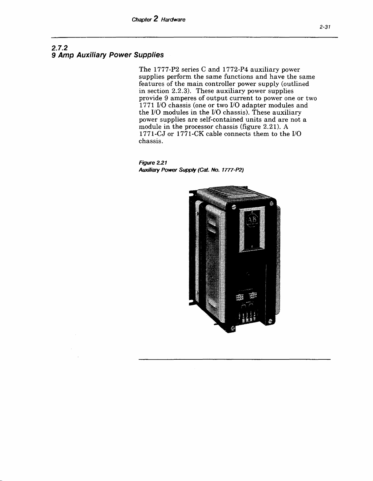
2.7.2
9
Amp
Chapter 2 Hardware
Auxiliary Power Supplies
The
1777-P2 series C
supplies
features
in
section 2.2.3). These
provide 9
110
1771
the
110
power
module
1771-CJ
chassis.
Figure 2.21
Auxiliary
supplies
and
perform
of
the
the
main
same
controller power
auxiliary
amperes
chassis
modules
in
the
or
1771-CK cable connects
Power
Supply
of
output
(one
or
in
the
110
are
self-contained
processor
(Cat. No. 1777-P2)
two
chassis
1772-P4
functions
auxiliary
and
supply
power
current
110
to power one or two
adapter
chassis). These
units
and
(figure 2.21). A
them
power
have
the
(outlined
supplies
modules
auxiliary
are
not
to
the
2-31
same
and
a
1/0
Artisan Technology Group - Quality Instrumentation ... Guaranteed | (888) 88-SOURCE | www.artisantg.com
Page 45

2-32
2.7.3
Power
Chapter 2 Hardware
Supply Compatibility
The
produced
summarizes
series:
1772-P1
as
and
1 772-P4 power
series
the
A,
functional
B,
and
C.
characteristics
supplies
The
following
have
of
each
been
Series
operates
operate
Series B
for
all
Series C
current
A--
The
original
only a PLC-2 family processor.
I/0
or
remote
use
--This
in
local or remote
series provides power sufficient
PLC-2 family processors.
--This
over
series
the
Series B (9
production level.
I/0
.
I/0
configuration
increased
the
amps
vs. 8 amps).
It
output
It
will
with
not
Artisan Technology Group - Quality Instrumentation ... Guaranteed | (888) 88-SOURCE | www.artisantg.com
Page 46

3.0
General
Assembly
and
Installation
Chapter 3
A well
of
necessary
in
A
installation
this
safety
and
supplement
govern
installing
with
Once
controller
installation
controller
the
are
CAUTION: You
manual
controller.
in
planned
the
programmable
for
this
chapter.
primary
chapter
of
local codes
components
contained
equipment
consideration
of
the
the
controller. These procedures
wiring
the
the
assembly
is completed,
system
before
Failure
planning
and
are
operator,
the
and
controller
of
these
in
damage.
layout
operation
pre
applicable codes
as
as
must
attempting
is
essential
controller.
the
installation
in
programmable
is safety.
sen
ted
with
of
the
installation
system
well
as
these
of
the
components
as
well
components
can
begin. Procedures for
well
as
mounting
the
first
part
read
and
to
to observe
for
the
Various
The
consideration
controlled
and
ordinances
practices.
should
procedures.
that
as
the
into
a workable
them
of
this
chapter.
understand
install
this
or
caution
installation
considerations
are
contained
controller
procedures
for
equipment,
are
intended
which
Personnel
become
planned
operate
familiar
make
layout,
assembling
in
an
enclosure
this
entire
the
may
result
the
up
in
to
the
3.1
Processor Assembly
3.1.1
Memory Module
Installation
The
processor is
memory modules
1772-ME
memory
-ME 16 module is used, only
Either
memory module is
processor
or
segments
the
chassis
shipped
which
-MEB module is
must
1772-ME, 1772-MEB, 1772-MES
inserted
(figure 3.4).
assembled,
are
be
ordered
to
be used,
installed.
batteries
in
the
rightmost
except
separately.
If
need be
for
batteries
a 1 772-MES
or
slot
the
If
a
and
or
installed.
1772-ME 16
of
the
Artisan Technology Group - Quality Instrumentation ... Guaranteed | (888) 88-SOURCE | www.artisantg.com
Page 47

3-2
3.1.2
Memory
Segments
Chapter 3 Assembly and
Memory
2048
Segments
and
8192
words, respectively,
sockets labeled A, B, C
The
(figure 3.1).
the
socket labeled A.
must
be
installed
D)
without
segments
Figure 3.1
Memory Module (Side
(table
first
leaving
3.A).
lnsta/lalion
(Cat. No. 1772-MT, -MS, -MS8), 512,
are
and
Don
memory
Each
in
alphabetical
an
open socket between
Vrew)
Memory
Segments
segment
subsequent
installed
the
memory module
is
installed
memory
succession (B, C
in
in
segment
and
installed
the
10677
Artisan Technology Group - Quality Instrumentation ... Guaranteed | (888) 88-SOURCE | www.artisantg.com
Page 48

Chapter 3 Assembly
Table 3.A
Memory
Segment Installation
and
Installation
3-3
NUIIIber
Memory
* Represents
The
memory
installation
end
of
the
other.
above
only
Figure 3.2
Memory
These
and
proper
Segment Keying
Socket
of
Segments
Memory
segments
(figure 3.2).
memory
posts
below
installation
Segment
segment
go
the
memory
Mounting
Screws
are
into
of
Socket
keyed to
There
and
holes
segment
the
ensure
are
two posts
only one
on
the
proper
on
post
on
memory module
socket,
permitting
memory segment.
one
the
ng
Posts
Artisan Technology Group - Quality Instrumentation ... Guaranteed | (888) 88-SOURCE | www.artisantg.com
Page 49

3-4
Chapter 3 Assembly
REMOVAL
and
Installation
£
l
e
CAUTION:
System
removed from
removing
followed,
installed
a memory segment.
damage
or
removed.
To remove a memory
the
following:
Step
1
Remove
2
Remove
Step
loosening
Figure 3.3
PLG-2120
Processor
' /
0
e
Power
the
memory module before
and
the
If
may
occur
segment
system
the
right
the
Front Panel
power.
two
to
the
from
front
thumb
Legend:
1.
Access memory and processor
modules by removing panel
backup
battery
installing
this
caution
memory
the
panel
is
segment
memory module, do
cover by
screws (figure 3.3).
not
must
or
being
be
l
2:0
e
nPOOOAAM
WP.o\NII.
e
61
110
"ACK
1
e
e
Step
3
DIACNOStiCI
0 0 0
H
·=
.,~='"
Remove
most
(figure 3.4).
~
-=:::·
plastic
the
memory module located
slot
of
the
processor
in
the
chassis
\Of:i,£2
16448
right-
Artisan Technology Group - Quality Instrumentation ... Guaranteed | (888) 88-SOURCE | www.artisantg.com
Page 50

Chapter 3 Assembly
Figure 3.4
Processor Module Locations
and
lnstallalion
3-5
0/0.ACK"'~
Power
Supply
Step
4
Step
5
Remove
the
Loosen
segment
socket.
the
module.
the
and
If
another
installed, refer
Step
6
Install
backup
section 3 .1. 2.
INSTALLATION
CAUTION: The
backup
memory module before
segment.
occur to
If
the
this
caution
memory
segment
battery
two
remove
housing
mounting
the
memory
and
screws
memory
segment
disconnect from
on
segment
to INSTALLATION section.
batteries
battery
installing
is
not
as
outlined
must
be removed from
or removing a memory
followed,
being
damage
installed
Memory
Module
the
memory
from
is to be
in
the
may
or removed.
10679
its
Artisan Technology Group - Quality Instrumentation ... Guaranteed | (888) 88-SOURCE | www.artisantg.com
Page 51

3-6
Chapter 3 Assembly
To
install
the
following:
Step
1
a memory
Remove
installed)
(figure 3.3).
and
Installation
segment
the
by loosening
right
on
front
the
memory module,
panel
the
cover
two thumb-screws
do
(if
Step
Step
Step4
Step
Step
3.1.3
Battery Backup Installation
The
size Alkaline cell
one
Memory Modules
memory/battery
Remove
2
most
(figure 3.4).
Remove
3
from
Insert
socket.
insertion
5
Secure
using
Install
6
section 3.1.2.
Battery
Lithium
the
plastic
the
the
module.
the
memory
The
of
the
the
two screws
backup
memory module located
slot
of
the
processor
battery
keying
the
segment
housing
segment
tabs
segment
to
the
on
batteries
and
into
aid
in
proper
(figure 3.2).
memory module by
the
segment.
as
outlined
in
the
chassis
disconnect
its
appropriate
in
right-
Housing (Cat. No. 1772-B1) accepts two D-
(batteries)
(Cat. No. 1771-BA)
or
cell (Cat. No. 1771-XO). See section 2.1.2,
(Battery
Backup), for a complete
compatibility list.
it
Alkaline cells provide
battery
months
Replace
may
A
Lithium
backup
not
lithium
later)
When
the
minimum
avoid loss
be
used
backup
at
the
time
450C (1130F).
them
with
at
any
cell provides
time
at a maximum
rechargeable. Replace
cell
may
be used
memory model.
the
STANDBY LOW
cell
or
cells
as
soon
life
of
the
of
memory
approximately
at
6QOC
(14QOF)
The
cells
periodic
intervals.
six
months
or
approximately
are
not
Alkaline cells
1772-ME memory model.
approximately 2 years
of
600C (1400F).
it
at
with
as
cell(s)
during
periodic
a 1 72-ME (revision K
indicator
possible,
cannot
cell
changes,
intervals.
starts
as
further
be predicted. To
of
rechargeable.
of
memory
This
cell is
A
or
flashing
be
sure
replace
the
12
Artisan Technology Group - Quality Instrumentation ... Guaranteed | (888) 88-SOURCE | www.artisantg.com
Page 52

Chapter 3 Assembly
and
Installation
3-7
processor is receiving power
firmly
the
seated
cell.
CAUTION: Memory
cell
when
must
re-enter
the
in
the
power
the
processor
contents
supply
entire
memory
is lost.
ALKALINE CELLS
To
install
Step
Step2
Step
Step
1
3
4
two D-size
Loosen
and
remove cover (figure 3.3).
Loosen
battery
Remove old
Install
housing
alkaline
thumb
battery
screws
housing
housing.
alkaline
the
cells
as
(figure 3.5).
and
the
memory module is
chassis
are
when
altered
if
you remove
is powered down
contents
cellsr do
on
right
screw
if
the
following:
front
and
cells.
indicated
on
battery
you
change
or
off. You
stored
panel
remove
the
data
cover
Figure
3.5
Battery Housing (with Alkaline Cells)
Step
5
Re-install
panel
battery
cover.
Orientation
Battery
housing
Contacts
and
+
right
10622
front
Artisan Technology Group - Quality Instrumentation ... Guaranteed | (888) 88-SOURCE | www.artisantg.com
Page 53

3-8
Chapter 3 Assembly
LITIDUM CELL
and
Installation
Perform
cell:
Step
1
Step
2
Step
3
Step
4
Step
5
the
following
Loosen
and
remove
Loosen
battery
Remove old
special
about
Information
steps
thumb
panel
battery
housing.
lithium
handling.
this,
refer
Application
screws
1770-2.18). Dispose
explained
lithium
are
alkaline,
step
Remove
Remove
battery
barrier
cell
4.
housing
as
in
that
and
remove
center
end
battery
indicated
contacts
for
installing
on
cover.
housing
cell.
For
additional
to
Lithium
of
the
publication.
go to
step
them
contact
screw)
in
figure 3.6.
the
right
front
screw
and
Lithium
cells
information
Battery
Data
(publication
old
lithium
Install
7.
If
old cells
and
continue
(figure 3.5).
(furthest
and
relocate
lithium
panel
remove
require
cell
new
with
from
in
center
cover
as
Figure 3.6
Battery
Step
Step
Housing
6
7
(with a
Uthium
Install
battery
the
housing
Re-install
panel
cover.
Cell)
lithium
battery
Orientation
Battery
cell
Contact
in
left
(figure 3.6).
housing
and
side
right
10681
of
front
Artisan Technology Group - Quality Instrumentation ... Guaranteed | (888) 88-SOURCE | www.artisantg.com
Page 54

3.2
1771
110
Chassis Assembly
Chapter 3 Assembly
and
Installation
3-9
3.2.1
Switch Group Assembly
All 1 771
size.
and
Located
backplane
you
rack)
depressed side
the
~are
Table
110
Chassis Switch Group Settings
Rack
I/0
chassis
The
only difference is how
I/0
modules
on
must
set
and
switch.
shown
3.8
are
controller
3 4
are
the
lower left side
switches
for
addressing
of
the
Settings
in
table
Switch
are
installed.
shutdown
for
assembled alike regardless
many
of
in a switch
field
wiring
the
110
chassis
group assembly
purposes (Le., slot
(figure 3. 7).
switch
indicates
these
switches for local
the
position
3.B.
For
Local
Rack Number *
5
of
arms
that
and
The
of
racks
==============================
1
2
3
4
5
6
7
ON ON
ON ON
ON
ON
OFF
OFF
OFF
* Limited to 2
Important:
adapter
rack
number
t-slot).
for
See
the
110
the
proper
and
ON
OFF
OFF
ON
OFF
OFF
ON ON
OFF
ON
OFF
ON
racks
user's
if
there
manual
setting
addressing
is
any
remote
for
your
of
these
switches for
mode ( 2-slot, 1-slot,
110
remote
110
Artisan Technology Group - Quality Instrumentation ... Guaranteed | (888) 88-SOURCE | www.artisantg.com
Page 55

3-10
Chapter 3 Assembly
Figure 3.7
110
1771
Socket
Chassis Switch Group
Switch Group
Assembly---
Input Power
Socket--~
and
Installation
Assembly
and
Power
Cable
3.2.2
Input Power Connection
You connect
supply
located below
the
(either
input
system
the
power cable from your power
or
auxiliary)
to
switch group assembly (figure 7).
Slot power supplies connect directly to
If
two
are
used,
table
Once
be used,
3.C for cable
it
has
and
to connect to
of
that
power cable
chassis
backplane
cable loose.
cable to
When
chassis,
the
using
the
shell connector
Universal
1/0
for complete
they
require a paralleling
and
power
been
length
the
Later,
determined
of corresponding power cable needed
110
chassis,
into
and
leave
you will connect
the
plug
the
9-pin socket on
the
power supply.
the
1771-P7 power
power connection is
at
the
top
of
the
Chassis
chassis
product
information.
supply
configurations.
type
the
other
this
supply
through
chassis. See
data
(pub. no. 1771-2.49)
the
9-pin socket
the
backplane.
cable. see
of
power
supply
9-pin connector
the
110
end
of
the
power
end
of
the
with
a 1771-A3B
the
15-pin O-
the
to
Artisan Technology Group - Quality Instrumentation ... Guaranteed | (888) 88-SOURCE | www.artisantg.com
Page 56

Chapter 3 Assembly
Table 3.C
Power Supplies and Power Cables
Chassis
and
Installation
Power
Supply
Cable
Length
Cable
Cat.
3-11
No.
1771-AlB
1771-A2B
1771-A4B
And
1771-A1
1771-A2
1771-A4
1771-A3B
1771-PSC
a
Use
1771-Pl ~ -P2
1771-P3,
1771-Pl a
1772-P1,
1777-PZ,
1771-Pl
1771-Pl 1
1771-P3,
with
1771-AlB,
-P4,
-P4
-P4
-P4,
-PS
-PS
A2B,
Chassis
5
ft.
No
Chassis
Use
1771-CT
power
Chassis
3
ft.
8
ft.
5
ft.
ft.
No
Cable
connection to
-A2B
or
A3B
and
A4B
1771-CL
(1.55m)
supplies
(.92m)
(2.45m)
(1.
(.3m)
-A4B
1771-CM
Cable
for paralleling
1771-CPl
1771-CK
1771-CJ
55m)
1771-CP2
1771-CL2
needed, Direct
1771-AlB,
Chassis
only.
Needed;
3.2.3
Power Supply
Configuration Plug
Artisan Technology Group - Quality Instrumentation ... Guaranteed | (888) 88-SOURCE | www.artisantg.com
Located between
is a Berg
is
the
chassis?"
o
o
This
stick
legend,
Do
Set
the
an
external
Set
the
if
you
jumper
connector. Stenciled on
"Using
the
plug
configuration
use a slot
directs
the
processor/adapter
power
supply
following:
to
the
right (N) position
power supply.
plug
power
the
supply
routing
to
the
module.
of
the
slot
the
module
if
ten
(Y)
RESET
and
slot
backplane
in
this
you use
position
signal.
0
Page 57

Chapter 3 Assembly
3-12
3.2.4
Keying Band Installation
and
Installation
Keying
with
each
keyed
to
assigned
110
module
slot.
Each
I/0
on
the
backplane
the
top socket.
right
side (figure 3.8) to
the
keying
in
the
publication
Figure 3.8
110
1771
Keying
Bands
I/0
accept
to
that
being
module
bands.
(part
of
chassis.
only
the
slot. Keying
installed
and
I/0
to
plug
The
socket
Keying
for
Band
Location Numbers
Cat.
No. 1771-RK)
Each
backplane
designated
guards
in
adapter
into.
has
aid
in
band
each
I/0
the
wrong
module
Install
guide
the
positioning
locations
module.
are
socket
type
of
against
I/0
has
keying
numbers
are
shipped
should
110
module
the
wrong
chassis
two sockets
bands
along
of
specified
be
in
the
10672
Keying
socket by
when
Artisan Technology Group - Quality Instrumentation ... Guaranteed | (888) 88-SOURCE | www.artisantg.com
bands
I/0
should
hand.
module
be
installed
These
bands
requirements
in
the
backplane
can
be easily repositioned
change.
Page 58

Chapter 3
3.2.5
110
Adapter Module Installation
Assembly
The
I/0
adapter
slot
of
the
locking
has
module
Figure 3.9
1771-AL
latch
been properly
in
110
I/0
chassis
and
place.
Adapter
and
Installation
module is
(figure 3.9).
insert
seated,
Module
installed
the
module.
close
the
in
Open
After
latch
the
left-most
the
the
to
module
module
secure
3-13
the
3.2.6
110
Module Installation
1771-AL
Adapter
Module
Module
?I
L~ing
Latch
~
8
rc~
I
A¢f1Vt~
""''"""<li
r-•
rt
I
(.Ufljlll(ji,Lifl
110
~~oOoltd"fllll
.....
!N
..
f
\
)r
il
i
f-:
~
()
~
-
I
rE9l
~
(!)
r-d.
\
~1
J..l
,___•
J
..t9l
)
~
---,
I
~
I
]
•
rE9l rE9l
~
I])
~
-
r----d
I
~
.b..}
~l
I
I
_:
!-·
rl
gL
-1:91
)
- -
~
~l
~--·
...{~
s
10684
After
corresponding
chassis.
Open
On
permit
(figure 3.10).
backplane
to
Artisan Technology Group - Quality Instrumentation ... Guaranteed | (888) 88-SOURCE | www.artisantg.com
the
seat
each
I/0
module slot
I/0
the
module locking
top
and
bottom
the
module
Do
socket;
it
firmly
module
to
be easily slid
not
force
but
rather
into
its
has
can
latch
of
each
the
sockets.
been
be
installed
to
insert
slot,
module
apply
keyed,
plastic
into
the
into
firm
the
into
the
guides
chassis
its
even
the
I/0
module.
pressure
I/0
Page 59

Chapter 3 Assembly
Figure 3.10
1771
110
Rack Components
PLC-2
m
1/0
.......
o
......
,,.
Adapter
Module
and
Installation
Aux. Power
Supply
G)
·---
....
..
~A
...
1
~
1/0
Power
Cable
~
..
Jt
"-.....A......-.Illlll==o:!lii!!=::!!!!=~~L....c..---------~
..
("<)
Module
Locking
Latch
1/0
Module
Modules
Guides
~
·---------T(?:------------··--·----T~~---------------!2
~
I I I •
: : I ! !
: i : ! i
1 l ! i i
: ! ! i :
i : i ! i
8slots:
j"---
-r.
!
!
~~.
:
12slots
i : : i i
l : : l :
: ! : i !
: l : : '
: l : : :
: : : : :
I : • f : f
i
~~
....
----------------------'------------------.1--
Module
Wiring
Locking
Extraction
Arm
Tab
Field
Arm
Wiring
:
16slots
:
{:~
Tab
: :
i
~=~
10685
After
each
pair
of
110
modules
installed,
module locking
module
its
field
Artisan Technology Group - Quality Instrumentation ... Guaranteed | (888) 88-SOURCE | www.artisantg.com
secure
has
been
wiring
these
latch
properly
arm
can
modules
(figure 3.1 0).
be
(a
in
seated
and
attached.
module group) is
place
After
locked
with
the
the
110
into
place,
Page 60

Chapter 3 Assembly
3.2.7
Field Wiring Arm Installation
and
Installation
3-15
A field
slot
the
snaps
(figure 3.12). Once
the
3.13).
wiring
connector edge
field
field
110
Figure 3.11
Example 1771 Field Wiring Arms·
wiring
is
shipped
field
wiring
onto
chassis,
When
arm
wiring
wiring
adapter
arm
with
arm
the
horizontal
it
pivots
the
110
pivots
arm
arm
upward
of
the
is needed for
is
modules ..
(figure 3.11) for
the
110
forms a
the
field
on
the
module is
I/0
used
on
each
110
module
chassis.
C-sha
bar
of
wiring
chassis
and
The
ped
bracket
the
110
arm
cross-bar
installed,
snaps
onto
lower
chassis
is
in
place
(figure
the
field
the
end
which
front
module (figure 3.14). No
the
the
adapter
1771-AL
module; a
and
1771-ASB
of
on
Series A
Artisan Technology Group - Quality Instrumentation ... Guaranteed | (888) 88-SOURCE | www.artisantg.com
Series 8
10671
Page 61

3-16
Chapter 3 Assembly
and
Installation
Figure 3.12
Snapping Field Wiring Arm onto Chassis
Field Wiring
Arm
Figure 3.13
Field Wiring Arms Installed
Locking tab holds
wiring arm when
position.
in
Artisan Technology Group - Quality Instrumentation ... Guaranteed | (888) 88-SOURCE | www.artisantg.com
Page 62

Chapter 3 Assembly
Figure 3.14
Field Wiring Arm (Wired)
and
Installation
3-17
3.3
System Installation Recommendations
There
controller
of
experience
provide
installations.
both
are
general
system.
product
with
useful
recommendations
These
testing
solid
guidelines for
recommendations
and
Allen-Bradley's
state
industrial
most
controller
~----Wiring
for
layout
are
of
the
cumulative
controls.
They
Field
Arm
a
result
These
controller
facility. Some of
user-supplied
Environmental
and
types
installation
Special
that
solid
which
voltage
Artisan Technology Group - Quality Instrumentation ... Guaranteed | (888) 88-SOURCE | www.artisantg.com
recommendations
an
integral
the
equipment
conditions,
local codes
of
layout
and
and
equipment.
care
should
may
contain
state
controls. Your
one
produces excessive
variations
may
are
intended
part
of
your
installation
are
general
the
ordinances
wiring
be
of
user-supplied
taken
or
in
more conditions
site
heat
also occur
to
aid
manufacturing
recommendations
in
nature.
individual
dictate
industrial
application,
the
specific
environments
adverse
may
include
or
electrical
in
equipment
some locations.
in
making
to
noise. Line
the
for
Page 63

3-18
3.3.1
Operating Temperature
3.3.2
Electrical Noise
Chapter 3 Assembly
For
most
and
applications,
controller components
range.
the
dissipation.
where a
equipment
this
enclosure to
spots
it
Thus,
the
enclosure is
There
substantial
either
case, blower fans
assist
near
the
controller.
may
introduce
usually
Installation
normal
within
proper
sufficient for
are,
however, some
amount
inside
or
may
air
circulation
harmful
convection cooling keeps
the
oo
spacing
of
of
heat
outside
components
is
the
be placed inside
and
Do
not
bring
contaminants
to 600C
operating
heat
applications
generated
enclosure.
the
to reduce
in
outside
or
dirt.
within
by
In
hot
air;
Important:
of
the
Grounding
this
publication
When
industrial
The
information
information
presented
we
in
our
present
Guidelines (publication no. 1770-4.1). See
the
controller is
environment,
for full
details.
operating
give special
in
possible electrical noise interference.
generators
solenoids,
operated
selector switches.
starters,
electrically
this
case,
of
the
Suppression
these
when
power to
A suggested electrical noise
AC
devices
to NEMA size
contactors
transient
the
RC
relays
in
figure 3.18.
include inductive loads
and
by
hard
hard
contacts
as
well
suppression
hard
contacts
for noise
types
of
loads
connected
the
controller.
(that
1)
of
size 2
voltage
network
are
suppressed
motors
along
as
and
contacts,
In
the
as
mechanically
is needed
in
generators
are
the
is, relays, solenoids,
is shown
and
limitation
shown
by free-wheeling diodes
motor
such
case
of
are
wired to
the
circuit
connected
same
suppression
in
figure 3.15.
above, a
is needed
in
figures
such
starters
as
reversing
at
the
with
may
as
AC line which
parallel
here
is a
summary
Wiring
and
a noise polluted
consideration
Potential
as
push
buttons
relays,
when
noise
they
and
motor
make
interlocked.
each
starter
In
device because
the
load.
be
necessary
output
devices or
brings
unit
for
small
and
starters
For
larger
varistor
in
addition
3.16
and
3.17. DC
as
shown
to
are
when
in
up
for
to
Artisan Technology Group - Quality Instrumentation ... Guaranteed | (888) 88-SOURCE | www.artisantg.com
Page 64

Chapter 3 Assembly
Figure 3.15
Typical Suppression for A Small
and
Installation
AC
Inductive Load
3-19
,......,------120V
0.5
•--
---1
11----.,..ni'NN'YvH..,.,..._...._
Discrete
Figure 3.16
Typical Suppression for 3-Phase Inductive Load
240/480V
AC
Component
' ' '
AC
------...,..1
I I
~-----------------~-~
I I
~-------------------~
ElectroCube
RG
1676-12
j..lf
2200
Equivalent
Electrocube
Part No. 1676-13
(3
Required)
Part#
10687
0.47J.Jf
2200
--j
f--------v.--
Oiscrete
(3
Artisan Technology Group - Quality Instrumentation ... Guaranteed | (888) 88-SOURCE | www.artisantg.com
Component
Required)
Equivalent
10688
Page 65

3-20
Chapter 3
Figure 3.17
Typical
Assembly
Suppression
1
.....
and
lnstallalion
for
Large AC
-----120V
CR4
Inductive
Loads
AC
--------1
.
.
:
I
I
I
I
: :
I I
'--------------------
Electrocube
Part No. RG1676-14
....
...
1
Figure
Typical
0.471Jf 220 0
cyJ
Discrete
General
3.18
Suppression for a Small DC
..,.....
Electric
______
e e
Component
MOV
(Metal
Inductive
v
oc--------"'"1
Equivalent
Oxide
Load
Varistor)
10689
PIV (Peak
must
Artisan Technology Group - Quality Instrumentation ... Guaranteed | (888) 88-SOURCE | www.artisantg.com
Inverse
be at least
Voltage)
twice
the
rating
applied
of
DC
diode
voltage
10690
Page 66

Chapter 3 Assembly
and
Installation
3-21
All possible sources
Best
results
networks
noisy device.
3.3.3
Constant Voltage Transformer
In
applications where
unstable
constant
voltage to
voltage to your devices.
constant
A
changes
voltage
transformer
system power supply
the
controller.
the
same
transformer.
The
constant
power
for
the
of
noise should be suppressed.
are
are
and
voltage
the
at
its
at
its
AC
rating
achieved
connected
subject to
transformer
power supply
voltage
transformer
input
output.
is required,
Output
line,
but
voltage
for
its
when
as
the
unusual
the
closely
AC
as
line is especially
variation,
to stabilize
as
well
compensates for voltage
in
order to
maintain a steady
If a constant
it
must
be connected to
and
all
input
devices connected to
devices should be connected on
before
transformer
load.
the
The
transformer
constant
must
system power supply should be
noise-suppressing
possible to
the
use a
the
input
as
the
input
voltage
the
voltage
have
a sufficient
at
power
least
rating
225V
A.
Determine
Step
1
Table
3.0
Power Supply Power Requirements
Power
the
proper size
transformer
Determine power supply power
the
nameplate
requirements
power supplies
Supply I
VA
or
product
for various system
are
listed
in
===============-=========
1771-P2
1771-P3
1771-P4
1771-P?
1772-Pl
1772-P4
1777-P2 85
1777
-P4
75
38W
79W
300
85
75
75
as
follows:
requirements
from
specifications. Power
and
auxiliary
table
3 .D.
Artisan Technology Group - Quality Instrumentation ... Guaranteed | (888) 88-SOURCE | www.artisantg.com
Page 67

3-22
Chapter 3 Assembly
Step
2
Determine
drawing
case power
which will also
transformer.
the
increased.
and
Installation
total
power from
requirements
When
transformer
power
draw
output
size is
requirements
this
transformer.
of
output
power from
devices
substantially
of
devices
this
are
inputs
Add worst
connected
3.3.4
Enclosure Considerations
3
Add
Step
input
device power
connected
Multiply
rating
input/output
These
size, allowing
supply
calculations
ample
throughout
necessary power for
Important:
transformer
the
manufacturer's
If
the
are
manufacturers
times
starting
the
motor VA
current
You should provide
controller.
protecting
The
the
controller from
(oil, moisture, conductive
corrosive
Standards
or
otherwise
established
Manufacturer's
types
based
provides
upon
the
components
enclosure which conforms to
device power
requirements
to
the
transformer
the
power
by 3. Add
device
determine
supply
this
figure to
requirement.
the
power to be delivered to
the
entire
110
output
motors
transformer
AC
devices.
devices connected to
andlor
motor
specifications. Some
recommend a reserve
requirement
surges.
an
enclosure to house
enclosure
is
the
primary
atmospheric
dust
or
harmful
by
the
National
airborne
Association (NEMA) define enclosure
the
degree
of
protection
mounted
the
NEMA
12 enclosures is preferred for solid
devices.
requirements
(only those
secondary).
VA (volt-ampere)
the
proper
transformer
the
cycle,
and
provide
starters,
capacity
in
order
to
handle
the
means
contaminants
particles,
or
substance).
Electrical
the
inside.
In
general,
standard
state
control
and
output
power
the
the
follow
of
6 to 8
of
any
enclosure
an
for Type
Mount
doors to be opened fully
and
important
disconnect device
Artisan Technology Group - Quality Instrumentation ... Guaranteed | (888) 88-SOURCE | www.artisantg.com
the
enclosure
components for
is
the
accessibility to
in
in
a position which allows
and
allows access to
testing
the
or
troubleshooting. Also
an
enclosure.
emergency
the
wiring
Page 68

Chapter 3 Assembly
The
controller
working
distance
the
enclosure to
enclosure door
account
examine
pockets
when
calculating
3.3.5
General Grounding Information
Grounding
installations.
grounding
the
effects
interference (EMI).
and
requires a minimum
depth
from
in
the
when
print
the
pockets
vendor's
mounted
is
an
With
has
added
of
noise
Installation
the
enclosure. Working
rear
of
the
chassis
the
inner-most
closed.
This
mounted
product
on
the
door
and
the
working
important
solid
value
due
safety
state
because
to electromagnetic noise
of
10 inches
depth
when
surface
would
on
the
mounted
of
the
take
into
door. Carefully
specifications for
stand
depth
off
of
an
measure
measurements
enclosure.
in
control systems,
it
helps to reduce
of
is
the
in
print
electrical
3-23
Allen-Bradley
their
enclosure
applicable codes
wiring
The
their
earth
the
grounding
enclosure
ground
is defined
equipment.
permanent
path
to
earth
fault
currents.
An
authoritative
the
National
programmable
must
and
controller.
path
should
(green wire).
as
the
central
All
earth
and
continuous
ground
source for
Electrical
be properly grounded. All
ordinances
for
the
be provided by a conductor to
ground
ground
for induced noise
Code published by
Fire Protection Association
Article 250
conductors
components. As defined
must
be
conduct
system
connections
permanent
which
of
the
and
methods
permanent
ground-fault
to
ground
to
a
nature.
grounding
code provides sizes
of
in
and
continuous
currents
with
the
grounding
Local codes
method
is permissible.
controller components,
should be observed
controller components,
In
this
manual,
for
all
connections
earth
electrical
must
and
ground
be
to provide a low-impedance
grounding
of
Boston,
safely
the
grounding
Code, a
that
minimum
conductor
and
currents
requirements
the
Massachusetts.
and
types
grounding
and
be able to safely
may
occur
impedance. Also,
must
ordinances
and/or
National
of
electrical
path
in
the
be
of
a
dictate
and
when
is
the
PC COMPONENT GROUNDING
The
recommended
programmable
in
is shown
contact
back
panel,
required.
figure 3.19. To
between controller components,
and
Paint
scraped from
with
the
component
Artisan Technology Group - Quality Instrumentation ... Guaranteed | (888) 88-SOURCE | www.artisantg.com
configuration
for
controller components
ensure
the
or
the
enclosure,
other
back
panel
mounting
nonconductive finishes
bare
where
bolts,
grounding
within
an
good electrical
the
enclosure
metal
contact
must
it
comes
nuts,
in
or
welded
contact
enclosure
is
be
Page 69

3-24
Chapter 3 Assembly
and
Installation
studs.
should be used to connect
enclosure. Connections should be
bolts
An
or
studs
8-gauge or
on
only one
larger
each
mounting
copper
component
made
or
equivalent
to
bracket
component's chassis.
Figure 3.19
Typical PLC-2130 Controller Grounding Configuration
Grounding Electrode
Enclosure
Equipment
Grounding
Conductor
in
the
the
mounting
of
Conductor
wire
the
To
Earth
Ground
(See
Section 2.0.)
Note: When using this grounding configuration, make no connections to EQUIP GND on the power
supply terminal strips. This can cause ground loops.
Each
vertical group of components is connected
(figure 3.19). These groups
bus
mounted
3.20
and
3.21). Connect
electrode system
on
the
through
(See
back
section 4.1.)
are
connected to a
panel
the
of
the
ground
bus
a grounding electrode
enclosure (figures
to
the
conductor.
10018
together
ground
grounding
Artisan Technology Group - Quality Instrumentation ... Guaranteed | (888) 88-SOURCE | www.artisantg.com
Page 70

Chapter 3 Assembly and Installation
3-25
Figure
Ground Bus Connection Details
3.20
Bolt
Star W\sher
\
Qlmi
Figure 3.21
Ground Bus Connections
Ground
Tapped
Bus
Hole
10021
Ground
Ground
Bus
®y-
Ground
Grounding
to
Earth
Equipment
Conductors
ENCLOSURE GROUNDING
Grounding
Bus
Mounting
0 0
Electrode
Ground
~
Lug
Conductor
(See section 2.0)
10022
The
enclosure
components
3.22).
Grounding
permanent
conduct
ground
electromagnetic noise
fault
that
must
and
continuous.
currents
contains
the
be connected to
paths
to
earth
They
currents
to
earth
ground
programmable
earth
ground
ground
must
must
be able to safely
and
with
possible
minimum
controller
(figure
be
impedance.
Artisan Technology Group - Quality Instrumentation ... Guaranteed | (888) 88-SOURCE | www.artisantg.com
Page 71

3-26
Chapter 3 Assembly
Figure 3.22
of
Details
Ground Connections
and
Installation
at
the Enclosure Wall
Enclosure Wall
3.4
Component Layout
Scrape
Star Washer
Paint
~
?I
Nut
To
Ground
Equipment
The
controller components
from
other
equipment
convection cooling. Convection cooling
column
surfaces.
specified
in
(1400F).
unobstructed
at
of
air
To
keep
temperature
the
base of
Because
upward
the
the
of
this
vertical
controller components is
and
over
Grounding
must
the
the
Conductor
be spaced sufficiently
enclosure walls to allow
controller module
controller modules
limits,
controller
this
must
cooling
not
vertical flow
spacing
above
and
important.
Bolt
Bus
10020
draws a vertical
within
air,
the
drawn
exceed 600C
of
air,
the
below
the
The
installation
upon
the
quantity
make
up
the
component
1.
Mount
above
a
other
much
supplies
2. Distance between
I/0
chassis
Artisan Technology Group - Quality Instrumentation ... Guaranteed | (888) 88-SOURCE | www.artisantg.com
layout
for a controller
and
types of components
is
dependent
system. The following rules govern
placement
the
processor
in
an
and
enclosure:
auxiliary
power
controller components because
higher
than
heat
any
other
auxiliary
is shown
dissipation
in
the
controller component.
power supplies
in
table
3.E.
power
that
supply
will
there
and
is
the
Page 72

Chapter 3 Assembly
Table 3.E
Power Cable Lengths
Chassis
and
Power
Installation
Supply
Cable
Length
Cable
Cat.
3-27
No.
1771-A1B
1771-A2B
1771-A4B
And
1771-Al
1771-A2
1771-A4
1771-A3B
1771-PSC
a
Use
1771-P1,
1771-P3, -P4,
1771-P7
1772-P1,
1777
1771-P7
1771-P1
1771-P3,
with
1771-AlB,
-P2,
-P2
a
-P4
-P4
-P4,
-P5
-P5
A2B,
Chassis
5
ft.
No
Chassis
Use
1771-CT
power
Chassis
3
ft. { .92m)
8
ft.
5
ft.
1
ft.
No
Cable
connection to
-A2B
or
A3B
and
A4B
1771-CL
{1.55m)
supplies
{2.45m)
{1.
{.3m)
-A4B
1771-CM
Cable
for
paralleling
1771-CP1
1771-CK
1771-CJ
55m)
1771-CP2
1771-CL2
needed, Direct
1771-AlB,
Chassis
only.
Needed;
3.
4.
5.
6.
Distance
chassis
for
Distance
Minimum
sides
Minimum
between
is limited by
the
power
between
distance
of
the
vertical
the
supply
I/0
processor
the
cable-feet
being
chassis
and
used.
is 3
between a major
enclosure is 4 inches.
separation
between
the
first
requirement
or
6 cable-feet.
component
major
I/0
components is 6 inches.
7.
Minimum
horizontal
separation
between
major
components is 4 inches.
8.
Minimum
and
the
9. Wiring ducts
no closer
Artisan Technology Group - Quality Instrumentation ... Guaranteed | (888) 88-SOURCE | www.artisantg.com
vertical
top
or
than
distance
bottom
and
terminal
2 inches to
between a major component
of
the
enclosure is 6 inches.
strips
any
should be
major
mounted
component.
and
the
Page 73

Chapter 3 Assembly
and
Installation
..,..___
t
6"
L
..
____J
4
?d
PLC-2/20
· 1 PLC-2/30
0~
--.,
=,
l
Figure
shows
Figure 3.23
Minimum
or
Proc«~ssor
maximum
-~~
·tE:B
@-=
F§t~
1-=
e
1/0
Chassis
c--. 1---f
l
~
,,..,._
411
--,1
1---f
1---f 1---f
J
l
l
3.23
shows
Spacing Dimensions
proper
110
chassis
6"
_L
___
4"----'1111'1
t-4"1
'c
~ l ~
~
component
configurations.
1-1
1---f 1---f 1---f f---.
---itlltlll
spacing.
1/0
Chassis
Figure
--'1
l
3.24
'c
I
I
.....
_
..
--·
~
-='
? •
::>~lll
_]I
I
.;.:;";.~
?
-·
I
--'1
l
I
I
f----11
~
l l
I
1---f
I
I
f----11
I
l
I
I I
~
R
l l l l
Ill
I
s
'<::;
,s
_
........
--·
~
:..t::
~
:,
Hfl
Jl
~·.~
? _!,..
I
~
H
I
.
I I I
..;;;;;;;,i.
.....,.
l~
ltlllll~~ll
I
I I
f----11
ill
I
---j
I
f----11
........
I :
c
'c
I
,c:
10691
Artisan Technology Group - Quality Instrumentation ... Guaranteed | (888) 88-SOURCE | www.artisantg.com
Page 74

PL.C-2/20
or
1/0 Rack No. 1
Chapter 3 Assembly
Figure 3.24
Maximum Rack Configuration
and
1/0 Rack No. 3
Installation
1771
1/0 Chassis (Any Size)
3.5
Component Mounting
1771
1/0
Chassis
!Any
Size) 1771 l/0 Chassis (Any Size)
The
controller components
contact
To
with
ensure
the
that
good electrical
back
panel
must
make solid electrical
for grounding purposes.
contact
has
established between controller components,
enclosure back panel,
contact
finishes
is required.
must
be scraped from
controller components
contact
welded
with
studs.
the
An 8-gauge or
wire should be used to connect
enclosure. Connections should be made to
bolts
or
studs
on only one
component's chassis. Figure 3.25 shows
and
the
Paint
or
if
necessary) where
component
mounting
enclosure,
other
nonconductive
the
back
mounting
larger
copper
each
component
bracket
bare
panel
bolts,
the
mounting
assembly details.
been
the
metal
(and
it
comes
nuts,
or
equivalent
in
mounting
of
the
in
or
the
Artisan Technology Group - Quality Instrumentation ... Guaranteed | (888) 88-SOURCE | www.artisantg.com
Page 75

3-30
Chapter 3 Assembly
Figure 3.25
Mounting Assembly Details
and
Installation
Stud Mounting
this Back Panel to
the Back
Enclosure
the
of
Wall of
Bolt
Ground Bus
Chassis to the
Back
Mounting of
or
a
Panel
Use a Wire Brush to remove
Paint from Threads to
allow
a Ground Connection
Scrape
Star Washer
a.
Paint and use
Flat Washer
~~
Star
washer
Ground·
Lug
\
Ground
Bus
or
Mounting
Bracket
Welded
Stud
Back Back Wall
Panel
of
Enclosure
Welded
Stud
~
Bolt
Scrape
Paint
and use
Star
Washer
Stud Mounting
Ground Bus
Chassis
Back
to
Panel
or
the
Each
(figure 3.19)
ground
(figures 3.20
a ground
enclosure (figure 3.22).
Avoid connecting more
because
compression
of
a
a
Flat
vertical group
and
these groups
bus
mounted
and
3.21).
lug
that
is mounted
the
connection
of
the
Washer
Scrape Paint
of
components is connected together :
are
connected to a·
on
the
back
than
can
metal
panel·of
The
ground
on
the
two lugs to a single bolt
become loose due to
lugs.
the
·enclosure
bus
is connected to
inside wall
of
the
10023
the
Artisan Technology Group - Quality Instrumentation ... Guaranteed | (888) 88-SOURCE | www.artisantg.com
Page 76

Chapter 3 Assembly
and
Installation
3-31
3.5.1
Processor
CAUTION:
chassis
back
panel
cause
Care
must
to
warp
when
is slightly curved.
stress
on
the
chassis backplane.
connection of
the
1/0 modules
sockets.
To avoid
spacing
enclosure
tightened.
as
needed, onto
spacing.
mounting
When
remove
weight
the
problem of
between
back
If
the
panel
spaces
the
When
this
nuts.
mounting
the
of
the
the
processor modules
processor chassis,
handle.
be
taken
mounted.
not
This
Chassis
printed
This
circuit
may
result
and
warping,
chassis
with
are
mounting
mounting
the
mounting
uneven,
bolts
insert
is accomplished,
processor,
the
in
order to reduce
making
to allow
may
distortion
board
in
the
their
the
I/0
occur
if
can
of
the
poor
backplane
carefully inspect
brackets
flat
or
studs
nuts
and
hand-.
washers,
to even
wrench-tighten
installer
may
elect to
the
it
easier
to
the
the
the
the
the
The
mounting
shown
in
in
section 3.5 to
dimensions for
figure 3..26. Use
mount
the
the
the
mounting
processor.
processor chassis
methods
outlined
are
Artisan Technology Group - Quality Instrumentation ... Guaranteed | (888) 88-SOURCE | www.artisantg.com
Page 77

3-32
Chapter 3 Assembly
Figure 3.26
Processor Chassis Mounting Dimensions
and
Installation
I
!
I
i,
I
1
'l
1
I :
........__
0
I
,II
1:
,.1,
,I;
I
::,
''I
I
I·
1
:1
ii
li
0
-=-~.......~
-
(22.4cm)
22.7cm
.1'1.
8.8"
8.92"
·m
-
J
r---·--
;
!~---
':
'.•
:
~
'
·;
''h.
J
[ 7
I I
:
I 1
//1
12.25"
(31.1cm)
J-
I""
.....,_
_____
!
e
11.25''
(28.6cm)
0
""-..
•
e
n
llEJ
e
.....
I
..
12.0"
(30.5cm)
./
..
o•··~
"•"'h.
"0
0
e
I
-J
G2
......
13.5"
(34.3cm)
I
3.5.2
110
Chassis
When
mounting
to remove
of
the
110
The
mounting
110
chassis
the
the
1/0 modules
chassis,
making
dimensions for
are
shown
110
chassis,
in
order to reduce
it
easier
the
in
figures 3.27, 28
the
installer
to handle.
4, 8, 12
and
and
may
the
weight
16 slot
29.
10693
elect
Artisan Technology Group - Quality Instrumentation ... Guaranteed | (888) 88-SOURCE | www.artisantg.com
Page 78

Chapter 3 Assembly
Figure
3.27
17714-S/ot
110
Chassis Mounting Dimensions
and
Installation
3-33
0.38"
~(9.6mm)
0
0
nm
Power
lJWl
Connector
0 0
0
0
o
8.51,
(216.1
12.41,
(315.~.
~I
j
mm)-
Figure 3.28
17718-s/ot
mm)
!-oOII-------(228.8)-------1
and
16-s/ot
_i
rrn-t~-"T""
(254
9.01"
-em-'
110
Chassis Mounting Dimensions
1.41"
(35.8 m m)
10.0"
mm)
D The plug shown is used with the
~
1/0 Adapter only.
PLC-2
The Battery Pack is used with
thEl
PLC-2 Mini-Processor and
thEl
Mini-PLC-2/15 Processor.
13161
0
0
~Power
u;Jj
Connector o
0
0
8.51"
(216.1 mm)
·'
12.41"
(315.2 mm)
0
j
r--
1
I
I
I
I
I
I
I
I
---
13.25"
(336.5
mm)
10.0"
(254.
mm)
-
9.01"
(228.
24.01"
(609.9
mm)
mm)
4-slot
13162
16-slot
Artisan Technology Group - Quality Instrumentation ... Guaranteed | (888) 88-SOURCE | www.artisantg.com
Page 79

3-34
Chapter 3 Assembly
Figure 3.29
177112-Siot
110
Chassis Mounting Dimensions
and
lnsta/lalion
0 0
8.70" -
(221.0 mm)
0
1:1.96"
(354.6 mm)
19.00"
(482.6 mm)
18.31"
(465.1
Ground
Stud
7.00"
(177.8 mm)
®
1
-l
5.48''
(139.2 mm)
l
13408
3.5.3
Auxiliary
Power Supplies
Use
the
mounting
mount
The
of
output
exceeds
required.
the
processor power
output
current
current
the
Three
110
4 amperes,
methods
chassis.
to power
requirement
of
the
listed below::
AC
o
o
o DC
See
no.
their
If
the
must
Auxiliary
AC
Auxiliary
Auxiliary
the
Programmable
SD-1.
7)
for a
performance specifications.
processor
use a
separate
Power
Power
Power
listing
contains
chassis.
supply
auxiliary
seven
Supply
Supply
supply
outlined
can
110
of a bulletin
auxiliary
in
section 3.5 to
provide
up
modules. When
1771
power supplies
supplies
(Cat. No. 1771-P2)
(Cat. No. 1777 -P2)
(Cat. No. 1777-P4)
Controller Products
of
all
power supplies
a core memory module, you
auxiliary
power
supply
to 4
amperes
the
110
are
are
catalog
and
for
the
total
rack
(pub.
110
Artisan Technology Group - Quality Instrumentation ... Guaranteed | (888) 88-SOURCE | www.artisantg.com
Page 80

Chapter 3
Assembly
and
Installation
3-35
1771-P2
There
AUXR,IARY
are
auxiliary
of
side
The
shown
Figure 3.30
Auxiliary
(Stand Atone)
the
mounting
in
Power
lo
e
/
/
/
/
POWER SUPPLY
two methods for
power supply.
I/0
chassis
or
dimensions for
figure 3.30.
Supply
(Cat. No. 1771-P2) Mounting Dimensions
l
e
)J
"
=,
"
-
-
"
-
-
"
-
-
-
-
-
..
mounting
Mount
it
as a stand
the
~
11.25"
(28.5cm)
the
1771-P2
on
either
alone
stand
the
unit.
alone
H..,._
+ •
,.
(.
1/r,;J~
·.l"'"''!o
"'"'"Ht
1
I
left
unit
2.0"
(S.Ocm)
-·
...
l!
are
10.0"
(25.4cm)
..
(~'.
I c
..
B.
1
..
7.16"
(18.2CmJ
~1
I
I
r
I
10696
Artisan Technology Group - Quality Instrumentation ... Guaranteed | (888) 88-SOURCE | www.artisantg.com
Page 81

3-36
Chapter 3
You
the
shipped
Assembly
should
110
chassis.
with
and
mount
Use
the
Installation
the
power
3.31).
Figure 3.31
Auxiliary Power
(110
Chassis Mounted)
2.12"
(53.8mm) j
Supply
(Cat. No. 1771-P2) Mounting Dimensions
I
.
.::-~::
..
::~.·::-~~:""~e
'''~*I""""COIII
Q"flll&h()tll001'1t0'
IUIIIII'fiiii!OIIIIIIIf,H"
UOlU'WII(O
1'
!l':ll',ot,(
IOU!,
'!r.ll'lllll(
t.ot~
power
the
mounting
supply
supply
screws
to
secure
on
the
that
it
left
side
are
(figure
of
10.0"
(254.0
1.41
II
(35.8 mm)
mm)
(315.2
12.41"
mm
8.51"
(216.1 mm)___...
NOTE: For ease of assembly, Power Supply and 1/0 Chassis should be assembled
0 The battery pack
is
used with the Mini-PLC-2 and Mini PLC-2/15 Processors
1777-P2, -P4
When
supplies,
modules
supply
To remove
power
Step
mounting
you
in
order
chassis , making
the
supply
1 Loosen
cover
27.79"
(705.9
mm)
AUXlLIARY
the
1777-P2, -P4
may
elect
to
to
reduce
power
chassis
the
panel
supply
perform
four
and
17.79"
mm)
(451.9
POWER SUPPLY
auxiliary
remove
the
it
easier
the
weight
to
handle.
power
of
module from
the
following
thumb
remove
screws
the
panel
the
the
steps:
on
power
supply
power
auxiliary
the
(figure
3.32).
"'Ground
Stud
as
a unit before mounting.
front
13164
Artisan Technology Group - Quality Instrumentation ... Guaranteed | (888) 88-SOURCE | www.artisantg.com
Page 82

Chapter 3 Assembly
Figure 3.32
Auxiliary
Dimensions
Power
Supply (Cat. No. 1777-P2. -P4) Mounting
and
Installation
3-37
f~
i:,
: 1 i
:'
i
':
l.U
fi
I
·I
I :
I,
'·
1
I
0 [
I
I
I
0 I
~
(22.4cm)
rL
i
'--'
8.8"
IJ
1
I
,
l
Panel
12.25"
(31.1cm)
Mounting
Screws
Screws
~
I...,..__
6.6"
(16.8cm)
_______...
0 ?
13.5"
(34.3cm)
10698
Step
2 Remove
Important:
into
any
socket
Mounting
auxiliary
After
properly
into
the
the
the
front
mounted,
auxiliary
the
and
remove
The
power
on
the
dimensions for
power
auxiliary
supplies
power
re-install
power
cover
panel.
two
bottom
the
power
supply
module cable does
auxiliary
the
1777-P2
are
shown
supply
the
supply
module
supply
power
in
chassis
power
chassis
mounting
module.
not
supply
and
chassis.
1777-P4
figure 3.32.
has
been
supply
and
module
re-attach
screws
plug
Artisan Technology Group - Quality Instrumentation ... Guaranteed | (888) 88-SOURCE | www.artisantg.com
Page 83

Chapter 3 Assembly
3-38
3.6
Incoming AC Wiring Guidelines
and
Installation
Important:
of
the
Grounding
this
publication
When
equipment
the
ground
3.34).
which
ground
Bradley
250-21
of
reducing
should
The
information
information
presented
Guidelines
for full details.
bringing
AC
power
grounding
bus
on
the
If
this
connection
is suspected of
current
(causing
programmable
National
Electric Code for recommended
objectionable
be
maintained
we
present
in
our
(publication
into
the
conductor
back
panel
results
in a ground
introducing
faulty
operation
should
an
here
Wiring
no. 1770-4.1). see
enclosure,
be connected to
(figures 3.33
objectionable
controller), refer to Article
for
ground
the
current.
enclosure
as
sections PC COMPONENT GROUNDING
GROUNDING.
earth
grounding
Local codes
method
and
ordinances
is permissible.
is a
summary
and
the
and
loop
of
the
Allen-
methods
Earth
ground
referenced
and
ENCLOSURE
dictate
in
which
Artisan Technology Group - Quality Instrumentation ... Guaranteed | (888) 88-SOURCE | www.artisantg.com
Page 84

Chapter 3 Assembly and
Figure 3.33
Typical
Grounded
Power
System
Distribution
Installation
(with Master Control
Relay)
of
3-39
a
Multiply
requirements
power
add
to
of
the
power
of
supplies by 2.5 to 3 and
all
other
determine
the
power
the
transformer.
the PLC
requirements
required rating
lncom•ng
Disconnect
Isolation
Step-Down
Transformer
AC
Backplane
Ground
IL1
yr-
To
Motor
Starters
Bus
Equipment
Grounding
Conductions
IL2
___
ll3
_,1
Enclosure
Wall
Grounding
Electrode
Conductor
to
Ground
(Ground
Electrode
System)
Earth
CAM
D
To
minimize
Allen·Bradley
f.J
To
minimize
Allen-Bradley
PC
Supply
Power
L•
L2
Output
Device
EMI
generation.
Cat. No. 1691·N2: For 220/240V AC.
EMI
generation.
Cat. No. 1676-14: For 220/240V AC.
connecting a Suppression
connecting a Suppression
network
Electrocube
network
Electrocube
CAMt
+ -
TO DC
Devices
is
recommended:
Part No.
Part No.
RG
is
recommended:
RG
1676-28.
1/0
For 120V AC.
1676-13.
For 120V AC.
Artisan Technology Group - Quality Instrumentation ... Guaranteed | (888) 88-SOURCE | www.artisantg.com
Page 85

3-40
Chapter 3 Assembly
3.34
Figure
Typical Power Distribution
Ungrounded System
and
Installation
(with
Master Control Relay)
lncommg
AC
of
an
Multiply
requirements
power
add
to
of
Use any
of
E-Stop Switches
in Series
r---------·--,
I I
the
power
of
supplies
all
other
determine
the transformer.
power
the
number
the
PLC
by
2.5 to 3 and
requirements
required rating
H4
--.
I
I
Isolation
I
I
Step-Down
I
I
Transformer
I
I
I
I
I
__ 2
Disconnect
Fuse
Backplane
Ground
Bus Wall
Equipment
Grounding
Conductions
To
Motor
Starters
,-----....,
v
Enclosure
I
I
I
I
Grounding
Electrode
Conductor
to Earth
Ground
(Ground
Electrode
System)
CAM
D
To
m1nimize EMI
Allen-Bradley
fJ
To
minimize
Allen-Bradley
CAM
PC
Power
Supply
Output
Device
generation.
Cat
No. 1691-N2: For 220/240V AC.
EMI
generation.
Cat. No. 1676-14: For 220/240V AC.
connecting a Suppression
connecting
a Suppression
CAM
network
Electrocube
network
Electrocube
CAM
is
recommended:
Part No.
is
recommended:
Part No.
L
+ -
TO
Devices
RG
RG
DC
1/0
1676-13.
1676-28.
For
120V AC.
For 120V AC.
10025
Artisan Technology Group - Quality Instrumentation ... Guaranteed | (888) 88-SOURCE | www.artisantg.com
Page 86

Chapter 3 Assembly
and
Installation
3-41
In a grounded
the
step-down
ground
In
fault
ground
When
supply
or
bus
an
ungrounded
indicator
bus
the
can
the
enclosure
conductor
AC
system, one side
transformer
(figure 3.35).
AC
system, one side
test
switch
(figure 3.34).
chassis
not
must
of
the
programmable
be directly connected to
ground
bus,
be connected to
EQUIPMENT GROUND
A
hard-wired
master
control relay, which you supply,
provides emergency power
devices. Since
placement
different
recommended. A
configuration
When
any
power to
still
supplied to
processor
its
inputs
the
of
several
locations,
typical
is
shown
of
the
emergency stop switches is
input
and
the
can
continue
and
outputs
master
emergency stop switches
its
installation
master
in
output
system
to
are
of
the
secondary
must
be connected to
must
be connected to
of
the
the
ground
the
controller's power
the
enclosure
an
on
the
shutdown
control
equipment
the
terminal
power supply's
for controller
relay
grounding
labeled
terminal
allows for
the
in
is
strongly
control
figures 3.
34
relay
and
3. 3 5.
operated,
devices is removed. Power is
power
operate
supply
even
though
so
that
all
the
powered down.
of
strip.
I/0
of
Important:
for a disconnect to
any
situation
energize 1/0 devices only.
replacing
within
controller system
CAUTION:
master
You
must
sufficient
Emergency stop switches
quick
The
master
where
output
the
enclosure, power
It
is
control
make
relay
certain
rating
and
easy
access to
control
the
controller.
the
operator
When
module fuses,
at
the
disconnect.
your
responsibility to
and
the
that
for
this
particular
must
the
relay
It
must
replacing
or
working
must
be
emergency
relay
contacts
be located to provide
operator
personnel. Emergency stop switches
series.
Do
not
WARNING:
the
user's
off
all
master
program.
input
control relay.
and
program
Any emergency stop
output
emergency stop switches
devices by de-energizing
is
not a substitute
is
intended
quickly de-
any
on
equipment
shut
off to
install
stop
the
switches.
have
application.
or
maintenance
must
be wired
switch
for
module,
the
in
must
turn
the
into
Artisan Technology Group - Quality Instrumentation ... Guaranteed | (888) 88-SOURCE | www.artisantg.com
Page 87

3-42
3.7
Wiring and Cabling
Installation
Chapter 3 Assembly
Before
wiring
3. 7 .2.
to
actually
guidelines
Wiring
components.
and
Installation
running
as
the
outlined
installation
signal
wiring,
in
sections 3. 7.1
will be discussed
refer
to
and
relating
the
WARNJNG: To avoid
equipment,
controller
within
Each
wire
or
common
shrink
can
be used.
In
addition
color to
signal
wires
may
specify
Wiring
within
It
is
strongly
the
Connection
chassis
size
--
disconnect
before
the
enclosure.
which
should
tubing,
or
to labeling, you
distinguish
wires
may
be red. Local
insulation
for
each
the
wiring
recommended
(figure
make
as
3.35
many
attempting
connects to
be
other
type
be blue
colors for
I/0
module
ducts
Diagram
and
injury
all
to
AC
any
an
personnel
and
wiring
I/0
appropriately
dependable
can
use
of
wiring
in
color
and
electrical
various
should
as
outlined
that
the
Addressing
3.36).
copies
The
as
you need.
and
damage
DC power to
the
installation
device, power source
labeled.
means
wire
signals.
AC
codes
types
be
bundled
in
section 3. 7 .2.
system
Forms
figures
Tape,
of
labeling
insulation
DC
I/0
I/0
signal
may
also
of
signals.
together
designer
for 1 771
are
full
to
use
110
A copy
installer
wiring
of
these
to
as
designed.
components
remain
should
in
the
troubleshooting
completed forms
ensure
has
proper
After
been
the
completed,
enclosure to serve
the
should
installation
wiring
these
as a wiring
system
become
of
of
forms
be
given
the
system's
the
controller
should
guide
necessary.
to
the
Artisan Technology Group - Quality Instrumentation ... Guaranteed | (888) 88-SOURCE | www.artisantg.com
Page 88

Chapter 3 Assembly
Figure
3.35
1771 8-Point Input/Output
and
Installation
Assignment
3-43
Form
LL.
0
UJ UJ
(!)
<( <(
D..
1-
c c
a:
UJ
z
Q
(f)
UJ
(U
I
-
-
_)=
J=
-
F=
-
)=
J=
-
~
•••••••••
r--
~
•••••••••
~
r--
•••••••••
1--
~
•••••••••
1--
r--
•••••••••
1J'
!I•
0 ~ ..
51
~
(J)
~
~'tz"'"'
~~
:~
~
~~
IIU'
r-;
~)
~
~·
...,
..
...,"'
....
G)
~
ClJ
8!~
0KD
<9
<lJ
9
R-J
:a-l[iS)Q}E)I<TJI>l~]
~91~0~~~9~
ll
V
1'0
IS)(;)}
9f<J)II>l
:~916J0~~
...
0 9
~
•
~
w
2:
<(
z
......
0
UJ
0
a:
D..
-
...--
-
==
::1..-
~
t---
lJ1
-
-
)=:
J=
J=
-
~
•••••
~
r--
•••••••••
I--
~
•••••"••
~
a;
....
""'
...
...
0..
oc
:ED
...,c
o:o
:::::
..
••
~)1~6<DI0~&Q>9!«l~~
~~~.~
I
J
5:!
~
L
@
~ei~0m~0e~
u r-; • v
I
Pi
liS)
Q>
g1m
'l>l
,;;a]]
~
~~
~
~888~
DOO
<fl
[L,
Artisan Technology Group - Quality Instrumentation ... Guaranteed | (888) 88-SOURCE | www.artisantg.com
Page 89

~
ALLEN-BRADLEY
~
A ROCKWELL INTERNATIONAL
PROJECT
NAME
____________________________________________
COMPANY
CONNECTION
Bulletin
DIAGRAM
1771
ADDRESSING
(16-point Modules)
dll~'
8AHERY
tNSTAll[D
1/0
Chassis
_
WORKSHEET
PAGE
DATE
________________________________
DESIGNER--~-------------------------
OF
_____________________
D
__
to,)
t
_
.....
:n
:::1
ra·
.....
§
...,CD
cp~
~&i
::::f
-
$"
1
g
-@
CS'
....
w
lao
~
~
~
!
t
lao
Cl)
~·
§
~
$"
l
~
::;
-
~
::i
Artisan Technology Group - Quality Instrumentation ... Guaranteed | (888) 88-SOURCE | www.artisantg.com
!DmD
12080
Page 90

3.7.1
Field
Wiring
Chapter 3 Assembly and
Considerations
When
categories
programmable
o
o
o
planning
of
I/0
power cables
to
I/0
chassis.
I/0
interconnect
status
the
Serial
data
110
chassis.
communication
highway;
serial
carry
110
data
chassis,
Installation
duct
layout,
wires
and
controller.
carry
cables
transmissions
computer
interconnect
transmissions
computers,
consider
cables
associated
regulated
(local 110)
cables,
interface;
cables (for
between
and
peripheral
the
5V
between
including
data
following
with
an
and
15V
carry
the
processor
110
data
handling;
remote
I/0)
processors,
printers.
3-45
A-B
power
and
and
1/0
3.7.2
Field
Wiring
Guidelines
o Low level DC
signals
constant
and
filters so
detected. Low level
analog,
response,
encoder/counter,
thermocouple,
modules.
o
AC
I/0
lines
greater
I/0
DC
The
following
programmable
are
applicable
inside
and
o All
routed
(feeding
does
National
(AC
the
conductors
degree
lines.
I/0
High
modules
are
controller
to
outside
AC
110
lines
with
up
to
not
violate local codes. Article
Electric
and
DC)
highest
voltage
in
1/0
lines
carry
their
input
that
DC
circuits
short
1/0
pulse
and
and
high
level DC
of
noise
immunity
level DC 1/0 lines
not
defined
general
wiring
components.
typical
the
machine
in
installations
enclosure:
and
100
horsepower
Code
the
same
high
power
requires
carried
the
duct.
low
voltage,
have
short
pulses
lines
other
can
connect
output,
low level DC
110
lines
than
fast
low level DC
connect
as
low level.
guidelines for A-B
These
for
wiring
level DC
lines
110
of
up
devices),
lines
to
if
300-3
that
all
duct
must
be
insulated
by
one
of
the
low
power
time
be
to
TTL,
1/0
have
a
to
all
guidelines
can
be
600V
AC
this
of
the
conductors
for
o All low level DC
shielded
and
communication
I/0
run
in a separate
cables
lines
may
must
also be
be
properly
duct.
run
Serial
with
these
lines.
Artisan Technology Group - Quality Instrumentation ... Guaranteed | (888) 88-SOURCE | www.artisantg.com
Page 91

3-46
3.7.3
110
Wiring Installation
Chapter 3 Assembly
o
1'0
power cables
cables
or
the
should
in a duct
enclosure.
and
Installation
remain
not
and
parallel
external
shared
with
1'0
interconnect
to
all
other
wiring
wiring
within
ducts
WARNING: To avoid
equipment,
controller
within
After
the
appropriate
module's wires.
terminal
wired
shown
Figure 3.37
Terminal Wiring
disconnect
before
the
enclosure.
wiring
wires for
(figure 3.37).
it
should
in
figure 3.38.
Completed on Field Wiring Arm
attempting
has
Attach
look
injury
all
AC
been
each
each
When
similar
to
personnel
and
any
run
in
module
wire to
the
to
the
and
damage
DC power to
wiring
the
ducts,
and
its
bundle
installation
module
pull
each
the
the
module is completely
field
wiring
arms
to
Artisan Technology Group - Quality Instrumentation ... Guaranteed | (888) 88-SOURCE | www.artisantg.com
Page 92

Chapter 3 Assembly
Figure
3.38
Module Wiring Completed
and
Installation
3-47
Field
........_---Wiring
Arm
Low level DC
require
as
shielded cable for
being
8761 cable
insulated
entire
wire
The
length.
and
shield's function is to reduce
induced noise
do
this,
wires
shield
as
must
recommended
110
chassis.
110
separated
or
equivalent.
twisted-pair
The
its
signal
at
any
the
shield
completely
be properly
grounding
The
110
modules (refer to section 3. 7
signal
from
all
other
This
with
a foil shield covering
twisted-pair
return.
point
must
as
along
cover
possible. Most
grounded
point
chassis,
provides a solid connection to
Exact
product
110
practices
Connect
at
the
of
wiring
module.
the
110
connections
data
publications
In
must
each
transmission
chassis
general, however, cable
follow
mounting
shield unconnected
the
cable. (Never
are
corresponding
these
outlined
cable shield to
at
the
ground
ends.)
transmission
wiring. Use a Belden
cable
has
a single
consists
the
the
the
enclosed
of a signal
effect
cable.
importantly,
only
at
one end.
for
the
shield is
when
earth
given
properly
ground.
in
the
individual
to
installation
here.
earth
bracket.
external
any
However, leave
110
cable
shield
device
.1)
as
well
its
of
In
order
pair
of
at
the
mounted,
the
specific
ground
end
at
both
to
the
The
Artisan Technology Group - Quality Instrumentation ... Guaranteed | (888) 88-SOURCE | www.artisantg.com
Page 93

3-48
Chapter 3 Assembly
and
Installation
Since
ground,
chassis
each
any
is also a connection to
To properly
arm,
perform
Step
1
Strip
the
(figure 3.39).
Figure 3.39
Trim Foil and
I/0
chassis
connections to a
must
be connected to
properly
earth
connect
the
end
Unnecessary Insulated Wire
a shielded cable
following steps:
3 feet
of
insulation
which is to connect to
mounted
ground.
at
from
earth
a field
the
cable
the
wiring
I/0
wiring
at
arm
Step
2
Step
Strip
necessary to
tape
might
arm
3
Trim
Then
from
is left
off
the
exposed foil.
insulate
or
shrink
tubing
otherwise come
terminals.
both
insulated
strip
approximately
the
end
of
each
at
its
full 3-foot
It
may
be
the
bare
drain
along
into
areas
contact
where
wires to 2-inch
3/8-inch
wire.
The
length
shield
(figure
wire
it
with
wiring
lengths.
of
insulation
strand
with
3.39).
Artisan Technology Group - Quality Instrumentation ... Guaranteed | (888) 88-SOURCE | www.artisantg.com
Page 94

Chapter 3 Assembly
Step
4
Connect
terminals
publication.
you
route
connect
the
cable.
Step
5
Connect
it
from
mounting
placed
and
the
tightened. A lug
In
applications
connected
necessary
connection
drain
only one
Figure 3.40
Cable Shield Grounding
and
Installation
the
specified
the
to
the
the
bare
the
wiring
bolt.
between
flat
washer
at
to provide a
of
wires
together
drain
insulated
in
Fold
back
cable.
user
device
drain
arm
The
shield
the
1/0
before
can
where
a single
many
wires or to solder
is
routed
wires
the
The
at
appropriate
the
bare
insulated
at
the
the
drain
other
wiring
wire
wires
end
wire to ground. Route
to
an
110
chassis
strand
chassis
the
be used (figure
many
1/0
shielded cables
chassis
ground
should
mounting
nut
is
3.40).
it
may
bus
for
several
at a wiring
arm
so
out.
3-49
arm
as
of
be
bracket
are
be
that
Belden No. 8761
Equivalent Wire
Cable
The
shielded cable
configured
as
or
at
shown
the
in
users
figure
device
3.41.
can
Field Wiring Arm
Ground Shield 1/0
Mounting Bolt
be
Artisan Technology Group - Quality Instrumentation ... Guaranteed | (888) 88-SOURCE | www.artisantg.com
Page 95

3-50
Chapter 3
Figure 3.41
Protection
Assembly
Shield
and
at
User's
Installation
Device
3.7.4
110
Chassis
Power Connection
The
I/0
sections
selected,
(figure 3.42).
on
each
power
cable connector left loose
to
the
that
1/0
chassis
3.2
the
end
supply
socket
chassis.
can
be powered by
and
3.4). Once
appropriate
The
cables
to allow for
has
been
on
the
power
the
power
110
power cable
have
different
proper
connection. After
installed,
as
outlined
supply
several
supply
pin
connect
in
section
providing
sources (see
is
must
be used
connectors
the
the
power
3.2
power for
Artisan Technology Group - Quality Instrumentation ... Guaranteed | (888) 88-SOURCE | www.artisantg.com
Page 96

Chapter 3 Assembly
Figure 3.42
1771
110
Chassis Power Supply Connections
and
Installation
3-51
,...--.--.-
........
9
:=!:?
•
U0
~
/.O-=
~-~
c.!~
;;;;;;;
:J=i
~
.....
._
..
~
..,;;,.o,.
LJ
.........
1/0
Power Cable
(Cat. No. 1771-CK
.--
e &
.....,
____,_
e
fl.ti,
-~
........
......,
l
PLC-2/30
Processor
1772-P1
1772-P4
1/0 Rack
Power
-..
or
1771-CJ)
?
~
0
~
1/
ORack
Po
wer
l
-~
? _, !--"'
I
~
~c·-··-,
0
~~~?~:.::
--{(
~
--··
~
lc:
2.
~
.:L'
......__
1/0 Power Cable
(Cat.
1777-P2, 1777-P4
Auxiliary
0
-i
l
No. 1771-CJ,
Power Suppl
.....,
( I
or
1771-CK)
-l
l
I
y
·~
lc
1771-P2
Auxiliary
Power Supply
3.7.5
Input Power Connections
WARNING: To avoid
equipment,
controller
within
disconnect
before
the
enclosure.
attempting
injury
all
AC
::0
.L
l
-=~
.:~:-
.~i
,·:
,___I/O
to
and
any
I
I
~
..
(Cat. No. 1771-CE,
personnel
DC power to
wiring
---j
(
l
L l L l l
II
I
Power Cable
and
installation
i
I
or
damage
the
........
I
I
1771-CD)
to
''"
~
Artisan Technology Group - Quality Instrumentation ... Guaranteed | (888) 88-SOURCE | www.artisantg.com
Page 97

3-52
Chapter
The
3 Assembly
following
and
paragraphs
connections to:
o
1772-P1, 1777-P2 Power
o 1 772-P4, 1777 -P4
o 1771-P2
Auxiliary
Installation
Auxiliary
Power
describe
Supply
Power
Supply
input
power
Supply
Power connections
similar.
wiring
See
the
details:
POWER SUPPLY
1771-P3,
1771-P?
to
other
appropriate
P4,
P5
power
supplies
product
PUB. PIN
1771-2.111
1771-2.93
1772-P1, 1777-P2 POWER SUPPLY
Located
module (processor
external
connections
supply
near
the
bottom
and
auxiliary
power
terminal
are
made
(figure 3.43).
module is factory
of
the
system
strip
to
shipped
power supply) is
which
configured for 120V AC
operation.
Figure 3.43
External Power Terminal
Strip
©'
2A/250
SLOW-BLOW
data
power
incoming
The
VAC
for
sheet
supply
system
I/0
for
an
AC
power
are
line
You
must
jumpers
both
terminal
Artisan Technology Group - Quality Instrumentation ... Guaranteed | (888) 88-SOURCE | www.artisantg.com
re-position
for 220/240V AC
120V
and
220/240V
strip
(figure 3.43).
the
external
AC
power
operation.
operation
terminal
Jumper
are
strip
positions for
shown
at
the
Page 98

Chapter 3 Assembly
AC
is
input
the
line connections
high
side
No connection is
when
the
grounding
is used. Also see
and
Installation
of
the
made
configuration
the
last
are
AC
line;
to
the
paragraph
made
L2
is
toLl
the
equipment
shown
in
and
L2.
low side.)
ground
in
terminal
figure
section 3.6.
3·53
(Ll
3.19
CAUTION:
jumpered
jumpering
operation
Be
for
either
on
or
damage
certain
the
terminal
that
the
power
120V or 220/240V AC.
strip
may
to
the
power supply.
1772-P4, 1777-P4 POWER SUPPLY
DC
input
(-)terminals
bottom
WARNING: Connect wires only to
of
the
may
Figure 3.44
External Power Terminal
(24V DC) connections
of
the
terminal
front
terminal
result
of
the
strip.
in
equipment
unit,
Strip (24 VDC Power Supplies)
as
Failure
damage
are
strip
located
shown
the
to observe
and/or
supply
cause
made
to
at
in
figure 3.44.
two
outer
this
personal
is correctly
Incorrect
improper
the
(+)and
the
terminals
warning
injury.
1/0
ro0o1rot'5ol
1/0
Power
Sockets~
1-----f""~
10A
SLOW-SLOW
RACK
POWER
~
10413
Artisan Technology Group - Quality Instrumentation ... Guaranteed | (888) 88-SOURCE | www.artisantg.com
Page 99

3-54
Chapter 3 Assembly
and
Installation
1771-P2 POWER SUPPLY
WARNING: To a void
equipment,
controller
within
AC
line connection is
located
(figure 3.45).
shipped
Figure 3.45
External Power Strip
disconnect
before
the
enclosure.
on
the
attempting
front
This
auxiliary
configured for 120V
injury
all
made
of
the
to
personnel
AC
and
any
wiring
to
the
auxiliary
power
AC
operation.
L2
fQUIP
G'IO
and
DC power to
installation
terminal
power
supply
strip
supply
is factory
damage
the
to
You
must
terminal
re-position
strip
positions for
are
shown
at
the
two
for 220/240V AC
both
120V AC
the
terminal
strip
metal
operation.
and
220/240V
(figure 3.45).
jumpers
AC
on
the
Jumper
operation
10704
Artisan Technology Group - Quality Instrumentation ... Guaranteed | (888) 88-SOURCE | www.artisantg.com
Page 100

Chapter 3 Assembly
Figure 3.46
Processor/Industrial Terminal Connection Diagram
PL.C-2/20 on PLC-2/30 Processor
r.:
......................
~
0 0
!]
·:::_:::JJ
and
Installation
3-55
Program Panel
Cable (cat. no. 1772-TC)
In
addition
AC operation,
supply
shipped
to repositioning
the
must
also be changed.
with
a 1
ampere
main
the
jumpers
AC fuse
The
slow-blow fuse
accommodate 120V AC operation.
to
operate
removed
with
AC
input
the
is
No connection is
when
is used. Also see
CAUTION:
jumpered
jumpering
operation
on 220/240V AC,
and
the
the
power supply,
line connections
high
side
the
grounding
Be
certain
for
either
on
the
or
damage
0.5
ampere
of
the
AC
made
to
configuration
the
last
that
120V
terminal
to
the 1 ampere
fuse,
must
be
installed.
are
made
line; L2 is
the
equipment
paragraph
the
power
or
220/240V AC. Incorrect
strip
may
the
power supply.
Interconnect
of
the.
auxiliary
power
When
shipped
to
L1
the
shown
in
section 3.6.
supply
cause
for 220/240V
power
supply
installed
the
fuse
is
to
power
must
supply
be
separately
and
L2. (L1
low side).
ground
in
terminal
figure
3.19
is correctly
improper
10705
is
Artisan Technology Group - Quality Instrumentation ... Guaranteed | (888) 88-SOURCE | www.artisantg.com
 Loading...