

Page 1
Installation Instructions
1756 EtherNet/IP Secure Communication Module
Catalog Number 1756-EN2TSC
Top ic Page
Before You Install the Module 4
Install the Module 5
Connect the Module to the Network 7
Status Indicators 9
Network Connectors and Cable 10
Specifications 11
Additional Resources 11
ATTENTION: Read this document and the documents listed in the Additional Resources section about installation, configuration and operation of this equipment before you install, configure, operate or maintain this product. Users are required to familiarize themselves
with installation and wiring instructions in addition to requirements of all applicable codes, laws, and standards. Activities including installation, adjustments, putting into service, use, assembly, disassembly, and maintenance are required to be carried out by suitably
trained personnel in accordance with applicable code of practice. If th is equipment is used in a manner not specified by the manufacturer, the protection provided by the equipment may be impaired.
注意:在安装、配置、操作和维护本产品前,请阅读本文档以及 “ 其他资源 ” 部分列出的有关设备安装、配置和操作的相应文档。除了所有适用规范、法律和标准的相关要求之外,用户
还必须熟悉安装和接线说明。 安装、调整、投运、使用、组装、拆卸和维护等各项操作必须由经过适当训练的专业人员按照适用的操作规范实施。 如果未按照制造商指定的方式使用该设
备,则可能会损害设备提供的保护。
ATENCIÓN: Antes de instalar, configurar, poner en funcionamiento o realizar el mant enimiento de este producto, lea este documento y los documentos listados en la sección Re cursos adicionales acerca de la instalación, configuración y operación de este equipo. Lo s
usuarios deben familiarizarse con las instrucciones de instalación y cableado y con los requisitos de todos los códigos, leyes y estándares vigentes. El personal debidamente capacitado debe realizar las actividades relacionadas a la instalación, ajustes, puesta en servicio, uso,
ensamblaje, desensamblaje y mantenimiento de conformidad con el código de práctica aplicable. Si este equipo se usa de una manera no especificada por el fabricante, la protección provista por el equipo puede resultar afectada.
ATENÇÃO: Leia este e os demais documentos sobre instalação, configuração e operação do equipamento que estão na seção Recursos adicionais antes de instalar, configurar, opera r ou manter este produto. Os usuários devem se familiarizar com as instru ções de instalação
e fiação além das especificações para todos os códigos, leis e no rmas aplicáveis. É necessário que as atividades, incluindo in stalação, ajustes, colocação em serviço, utilização, montagem, desmontagem e manutenção sejam realizadas por pessoal qualificado e especializado,
de acordo com o código de prática aplicável. Caso este equipamento seja utilizado de manei ra não estabelecida pelo fabricante, a proteção fornecida pelo equipamento pode ficar prejudicada.
ВНИМАНИЕ: Перед тем как устанавливать, настраивать, эксплуатиров ать или обслуживать данное оборудование, прочитайте этот документ и документы, перечисленные в разделе «До полнительные ресурсы». В этих документах изложен ы сведения об
установке, настройке и эксплуатации данного оборудован ия. Пользователи обязаны ознакомиться с инструкциями по установке и прокладке соединений, а также с требованиями всех применимых норм, законов и стандартов. Все действия, включая
установку, наладку, ввод в эксплуатацию, испол ьзование, сборку, разборку и техническое обслуживание, должны выполняться обученным персоналом в соответствии с применимыми нормами и правилами. Если оборудование используется не
предусмотренным производителем образом, защита оборудования может быть нарушена.
注意 : 本製品を設置、構成、稼動または保守する前に、本書および本機器の設置、設定、操作についての参考資料の該当箇所に記載されている文書に目を通してください。ユーザは、
すべての該当する条例、法律、規格の要件に加えて、設置および配線の手順に習熟している必要があります。 設置調整、運転の開始、使用、組立て、解体、保守を含む諸作業は、該当
する実施規則に従って訓練を受けた適切な作業員が実行する必要があります。 本機器が製造メーカにより指定されていない方法で使用されている場合、機器により提供されている保護
が損なわれる恐れがあります。
ACHTUNG: Lesen Sie dieses Dokument und die im Abschnitt „Literaturverweise“ genannten Dokumente zur Installation, Konfiguration und Bedienung dieser Ausrüstung sorgfältig durch, bevor Sie dieses Produkt installieren, konfigurieren, bedienen oder instandsetzen.
Benutzer müssen sich mit den Anweisungen zur Installation und Verdrahtung vertraut machen und müssen die Anforderungen aller geltenden Vorschriften, Gesetze und Normen kennen. Aktivitäten wie Installation, Einstellung, Inbetriebnahme, Verw endung, Montage,
Demontage und Instandsetzung müssen durch ausreichend geschultes Personal in Übereinstimmung mit den geltenden Durchführungsvorschriften ausgeführt werden. Wenn diese Ausrüstung in einer Weise verwendet wird, die nicht vom Hersteller angegeben wurde,
kann der von der Ausrüstung bereitgestellte Schutz beeinträchtigt sein..
ATTENTION : Lisez ce document et les documents listés dans la section Ressources complémentaires relatifs à l’installation, la configuration et le fonctionnement de cet équipement ava nt d’installer, configurer, utiliser ou entretenir ce produit. Les utilisateurs doivent se
familiariser avec les instructions d’installation et de câblage en plus des exigences relatives aux codes, lois et normes en vigueur. Les activités relatives à l’installation, le réglage, la mise en service, l’utilisation, l’assemblage, le démontage et l’entretien doivent être réalisées
par des personnes formées selon le code de pratique en vigueur. Si cet équipement est utilisé d’une façon qui n’a pas été définie par le fabricant, la protection fournie par l’équipement peut être compromise.
주의: 본 제품 설치, 설정, 작동 또는 유지 보수하기 전에 본 문서를 포함하여 설치, 설정 및 작동에 관한 참고 자료 섹션의 문서들을 반드시 읽고 숙지하십시오. 사용자는 모든 관련 규정, 법규
및 표준에서 요구하는 사항에 대해 반드시 설치 및 배선 지침을 숙지해야 합니다. 설치, 조정, 가동, 사용, 조립, 분해, 유지보수 등 모든 작업은 관련 규정에 따라 적절한 교육을 받은 사용자를
통해서만 수행해야 합니다 . 본 장비를 제조사가 명시하지 않은 방법으로 사용하면 장비의 보호 기능이 손상될 수 있습니다 .
ATTENZIONE Prima di installare, configurare ed utilizzare il prodotto, o effettuare interventi di manutenzione su di esso, leggere il presente documento ed i documenti elencati nella sezione “Altre risorse”, riguardanti l’installazione, la configurazione ed il funzionamento
dell’apparecchiatura. Gli utenti devono leggere e comprendere le istruzioni di installazione e cablaggio, oltre ai requisiti previsti dalle leggi, codici e standard applicabili. Le attività come installazione, regolazioni, utilizzo, assemblaggio, disassemblaggio e manutenzione
devono essere svolte da personale adeguatamente addestrato, nel rispetto delle procedure previste. Qualora l’apparecchio venga utilizzato con modalità diverse da quanto previsto dal produttore, la sua funzione di protezione potrebbe venire compromessa.
DİKKAT: Bu ürünün kurulumu, yapılandırılması, işletilmesi veya bakımı öncesinde bu dokümanı ve bu ekipmanın kurulumu, yapılandırılması ve işletimi ile ilgili İlave Kaynaklar bölümünde yer listelenmiş dokümanları okuyun. Kullanıcılar yürürlükteki tüm yönetmelikler,
yasalar ve standartların gereksinimlerine ek olarak kurulum ve kablolama talimatlarını da öğrenmek zorundadır. Kurulum, ayarlama, hizmete alma, kullanma, parçaları birleştirme, parçaları sökme ve bakım gibi aktiviteler sadece uygun eğitimleri almış kişiler tarafından
yürürlükteki uygulama yönetmeliklerine uygun şekilde yapılabilir. Bu ekipman üretici tarafından belirlenmiş amacın dışında kullanılırsa, ekipman tarafından sağlan an koruma bozulabilir.
注意事項:在安裝、設定、操作或維護本產品前,請先閱讀此文件以及列於 「其他資源」章節中有關安裝、設定與操作此設備的文件。使用者必須熟悉安裝和配線指示,並符合所有法規、
法律和標準要求。包括安裝、調整、交付使用、使用、組裝、拆卸和維護等動作都必須交由已經過適當訓練的人員進行,以符合適用的實作法規。如果將設備用於非製造商指定的用途
時,可能會造成設備所提供的保護功能受損。
POZOR: Než začnete instalovat, konfigurovat či provozovat tento výrobek nebo provádět jeho údržbu, přečtěte si tento dokument a dokumenty uvedené v části Dodatečné zdroje ohledně instalace, konfigurace a provozu tohoto zařízení. Uživatelé se musejí vedle požadavků
všech relevantních vyhlášek, zákonů a norem nu tně seznámit také s pokyny pro instalaci a elektrické zapojení. Činnos ti zahrnující instalaci, nastavení, uvedení do provozu, už ívání, montáž, demontáž a údržbu musí vykonávat vhodně proškolený personál v souladu
s příslušnými prováděcími předpisy. Pokud se toto zařízení používá způsobem neodpovídajícím specifikaci výrobce, může být narušena ochrana, kterou toto zařízení poskytuje.
UWAGA: Przed instalacją, konfiguracją, użytkowaniem lub konserwac ją tego produktu należy przeczytać niniejszy dokument oraz wszystkie dokumenty wymienione w sekcji Dodatkowe źródła omawiające instalację, konfigurację i procedury użytkowania tego urządzenia.
Użytkownicy mają obowiązek zapoznać się z instrukcjami dotyczącym i instalacji oraz oprzewodowania, jak również z obowiązującymi kodeksami, prawem i normami. Działania obejmujące instalację, regula cję, przekazanie do użytkowania, użytkowanie, montaż,
demontaż oraz konserwację muszą być wykonywane przez odpowiednio przeszkolony personel zgodnie z obowiązującym kodeksem postępowania. Jeśli urządzenie jest użytkowane w sposób inny niż określony przez producenta, zabezpieczenie zapewniane prze z
urządzenie może zostać ograniczone.
OBS! Läs detta dokument samt dokumentet, som står li stat i avsnittet Övriga resurser, om installation, kon figurering och drift av denna utrustning innan du installerar, konfigurerar eller börjar använda eller utföra underhållsarbete på produkten. Användare måste bekanta
sig med instruktioner för installation och kabeldragning, förutom krav enligt gällande koder, lagar och standarder. Åtgärder som installation, justering, service, användning, mon tering, demontering och underhållsarbete måste utföras av personal med lämplig utbildning
enligt lämpligt bruk. Om denna utru stning används på ett sätt som inte anges av tillverkaren kan det hända att utrustningens skyddsanordningar försätts ur funktion.
LET OP: Lees dit document en de documenten die genoemd worden in de paragraaf Aanvullende informatie over de installatie, configuratie en bediening van deze apparatuur voord at u dit product installeert, configureert, bediend of onderhoudt. Gebruikers moeten zich
vertrouwd maken met de installatie en de bedradingsinstructies, naast de vereisten van alle toepasselijke regels, wetten en normen. Activiteiten zoals het in stalleren, afstellen, in gebruik stellen, ge bruiken, monteren, demonteren en het u itvoeren van onderhoud mogen
uitsluitend worden uitgevoerd door hiervoor opgeleid personeel en in overeenstemming met de geldende praktijkregels. Indien de apparatuur wordt gebruikt op een wijze die niet is gespecificeerd door de fabrikant, dan bestaat het gevaar dat de beveiliging van de
apparatuur niet goed werkt.
Page 2
1756 EtherNet/IP Secure Communication Module
IMPORTANT
ATTENTION:
• Before installing, configuring, operating, or maintaining this product, read this document and the documents listed in the additional
resources section for installing, configuring, or operating equipment. Users should familiarize themselves with installation and wiring
instructions in addition to requirements of all applicable codes, laws, and standards.
• Installation, adjustments, putting into service, use, assembly, disassembly, and maintenance shall be carried out by suitably trained
personnel in accordance with applicable code of practice. In case of malfunction or damage, no attempts at repair should be made. The
module should be returned to the manufacturer for repair. Do not dismantle the module.
• If this equipment is used in a manner not specified by the manufacturer, the protection provided by the equipment may be impaired.
• This equipment is certified for use only within the surrounding air temperature range of 0…60 °C (32…140 °F). The equipment must not
be used outside of this range.
• Use only a soft dry anti-static cloth to wipe down equipment. Do not use any cleaning agents.
• The USB port is intended for temporary local programming purposes only and not intended for permanent connection.
• The USB cable is not to exceed 3.0 m (9.84 ft) and must not contain hubs.
Any illustrations, charts, sample programs, and layout examples that are shown in this publication are intended solely for the
purposes of example. Since there are many variables and requirements that are associated with any particular installation, Rockwell
Automation® does not assume responsibility or liability for actual use based on the examples that are shown in this publication.
Table 1 - Environment and Enclosure
ATTENTION: This equipment is intended for use in a Pollution Degree 2 industrial environment, in overvoltage Category II applications (as
defined in EN 60664-1), at altitudes up to 2000 m (6562 ft) without derating.
This equipment is not intended for use in residential environments and may not provide adequate protection to radio communication services in
such environments.
This equipment is supplied as open-type equipment for indoor use. It must be mounted within an enclosure that is suitably designed for those
specific environmental conditions that are present and appropriately designed to prevent personal injury resulting from accessibility to live
parts. The enclosure must have suitable flame-retardant properties to prevent or minimize the spread of flame, complying with a flame spread
rating of 5VA or be approved for the application if non-metallic. The interior of the enclosure must be accessible only by the use of a tool.
Subsequent sections of this publication may contain additional information regarding specific enclosure type ratings that are required to comply
with certain product safety certifications.
In addition to this publication, see the following:
• Industrial Automation Wiring and Grounding Guidelines, publication 1770-4.1, for additional installation requirements
• NEMA 250 and EN/IEC 60529, as applicable, for explanations of the degrees of protection provided by enclosures.
2 Rockwell Automation Publication 1756-IN618A-EN-P - September 2015
Page 3
Table 2 - North American Hazardous Location Approval
1756 EtherNet/IP Secure Communication Module
The following information applies when operating this equipment in hazardous
locations:
Produc ts marked “C L I, DIV 2, G P A, B, C, D” are suitab le for use i n Class I Di vision 2 G roups A, B, C,
D, Hazardous Locations and nonhazardous locations only. Each product is supplied with
markings on the rating nameplate indicating the hazardous location temperature code. When
combining products within a system, the most adverse temperature code (lowest “T” number)
may be used to help determine the overall temperature code of the system. Combinations of
equipment in your system are subject to investigation by the local authority having jurisdiction
at the time of installation
WARNING: EXPLOSION HAZARD
• Do not disconnect equipment unless power has been
removed or the area is known to be nonhazardous.
• Do not disconnect connections to this equipment
unless power has been removed or the area is known to
be nonhazardous. Secure any external connections that
mate to this equipment by using screws, sliding
latches, threaded connectors, or other means provided
with this product.
• Substitution of components may impair suitability for
Class I, Division 2.
• If this product contains batteries, they must be
changed only in an area known to be nonhazardous.
Informations sur l'utilisation de cet équipement en environnements dangereux:
Les produits marqués “CL I, DIV 2, GP A, B, C, D” ne conviennent qu'à une utilisation en
environnements de Classe I Division 2 Groupes A, B, C, D dangereux et non dangereux. Chaque
produit est livré avec des marquages sur sa plaque d'identification qui indiquent le code de
température pour les environnements dangereux. Lorsque plusieurs produits sont combinés
dans un système, le code de température le plus défavorable (code de température le plus
faible) peut être utipements dans le système sont sujettes à inspection par les autorités locales
qualifiées au moment de l'installation.
WARNING: RISQUE D'EXPLOSION
• Couper le courant ou s'assurer que l'environnement est
classé non dangereux avant de débrancher
l'équipement.
• Couper le courant ou s'assurer que l'environnement est
classé non dangereux avant de débrancher les
connecteurs. Fixer tous les connecteurs externes reliés
à cet équipement à l'aide de vis, loquets coulissants,
connecteurs filetés ou autres moyens fournis avec ce
produit.
• La substitution de composants peut rendre cet
équipement inadapté à une utilisation en
environnement de Classe I, Division 2.
• S'assurer que l'environnement est classé non
dangereux avant de changer les piles.
Table 3 - European Hazardous Location Approval
The following applies to products marked II 3 G. Such modules:
• are Equipment Group II, Equipment Category 3, and comply with the Essential Health and Safety Requirements relating to the design and construction of such equipment given in Annex II to
Directive 94/9/EC. See the EC Declaration of Conformity at http:/www.rockwellautomation/products/certification.com for details. The type of protection used is “Ex nA nC IIC T4 Gc” according to
EN 60079-15:2010 and EN 60079-0:2012.
• are intended for use in areas in which explosive atmospheres caused by gases, vapors, mists, air or dust mixtures are unlikely to occur, or are likely to occur only infrequently and for short
periods. Such locations correspond to Zone 2 classification according to ATEX directive 1999/92/EC.
.
Table 4 - Special Conditions for Safe Use
WARNING: Special Conditions for Safe Use
• This equipment is not resistant to sunlight or other sources of UV radiation.
• This equipment shall be mounted in an ATEX/IECEx Zone 2 certified enclosure with a minimum ingress protection rating of at least IP54 (as
defined in EN/IEC 60529) and used in an environment of not more than Pollution Degree 2 (as defined in EN/IEC 60664-1) when applied in
Zone 2 environments. The enclosure must be accessible only by the use of a tool.
• This equipment shall be used within its specified ratings defined by Rockwell Automation.
• Provision shall be made to prevent the rated voltage from being exceeded by transient disturbances of more than 140% of the rated voltage
when applied in Zone 2 environments.
• The instructions in the user manual shall be observed.
• This equipment must be used only with ATEX/IECEx certified Rockwell Automation backplanes.
• Secure any external connections that mate to this equipment by using screws, sliding latches, threaded connectors, or other means provided
with this product.
• Do not disconnect equipment unless power has been removed or the area is known to be nonhazardous.
• Do not use the USB port in hazardous locations.
Rockwell Automation Publication 1756-IN618A-EN-P - September 2015 3
Page 4
1756 EtherNet/IP Secure Communication Module
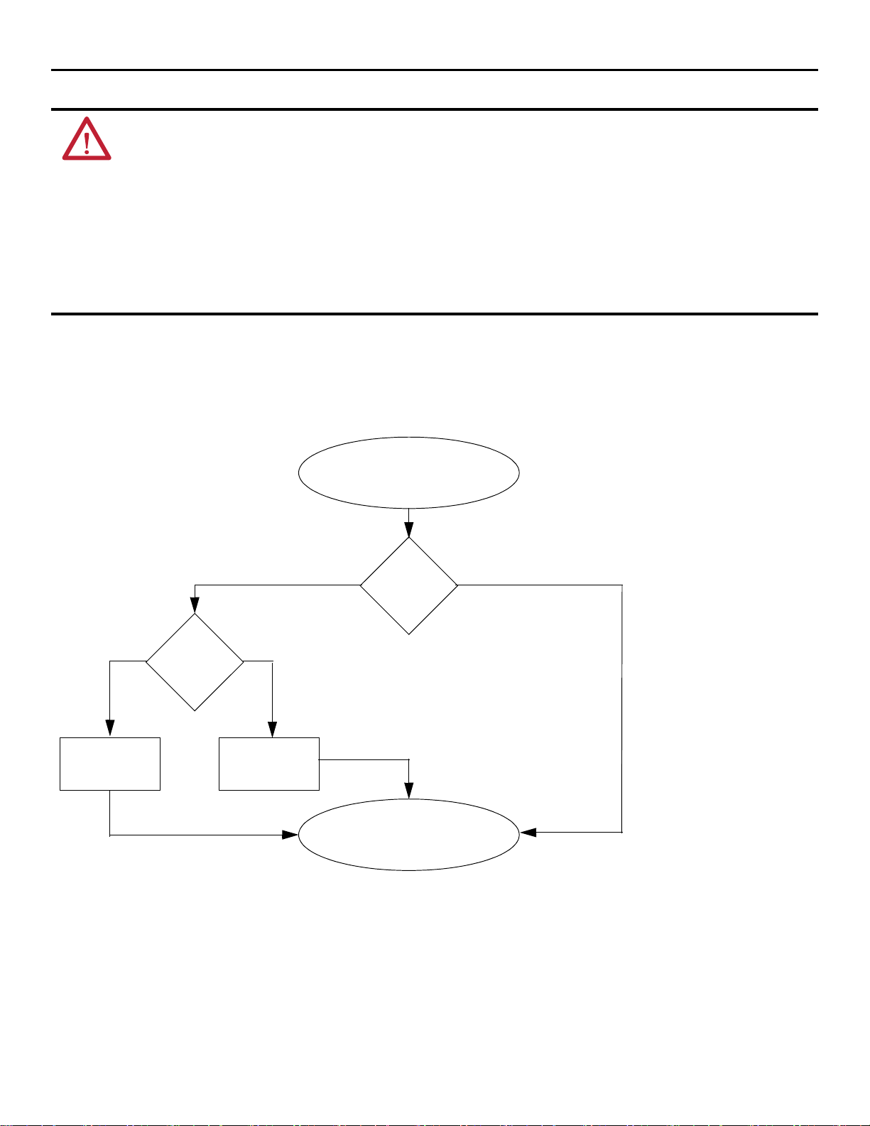
Module Powerup
Module has an IP address.
Switches set
from
001…254?
YesNo
Is DHCP or
BOOTP enabled?
YesNo
Module requests
address from DHCP/
BOOTP server.
Module uses IP address
that is stored in
nonvolatile memory.
Tabl e 5 - Prevent Electrostatic Discharge
ATTENTION:
• This equipment is sensitive to electrostatic discharge, which can cause internal damage and affect normal operation. Follow these guidelines
when you handle this equipment:
• Touch a grounded object to discharge potential static.
• Wear an approved grounding wrist strap.
• Do not touch connectors or pins on component boards.
• Do not touch circuit components inside the equipment.
• Use a static-safe workstation, if available.
• Store the equipment in appropriate static-safe packaging when not in use.
Before You Install the Module
To operate an EtherNet/IP communication module on an EtherNet/IP network, you must assign a network IP address.
Figure 1 - How the IP Address is Set
4 Rockwell Automation Publication 1756-IN618A-EN-P - September 2015
Page 5

1756 EtherNet/IP Secure Communication Module
Slot 2Slot 0
Slot 1 Slot 3
ControlLogix Chassis
20806
Install the Module
You can install or remove a module while chassis power is on. To install the module, follow these steps.
Table 6 - Removal and Insertion Under Power
WARNING: When you insert or remove the module while backplane power is on, an electrical arc can occur. This could cause an explosion in
hazardous location installations.
Be sure that power is removed or the area is nonhazardous before proceeding. Repeated electrical arcing causes excessive wear to contacts on
both the module and its mating connector. Worn contacts may create electrical resistance that can affect module operation.
Table 7 - Multi-point Network Communication
WARNING: If you connect or disconnect the communication cable with power applied to this module or any device on the network, an
electrical arc can occur. This could cause an explosion in hazardous location installations.
Be sure that power is removed or the area is nonhazardous before proceeding.
1. Determine module slot location.
2. Install the communication module in any slot in a ControlLogix® or ControlLogix-XT™ chassis.
You can install multiple communication modules in the same chassis.
This example shows chassis slot numbering in a 4-slot ControlLogix chassis. Slot 0 is the first slot and is always the left-most slot in
the chassis.
WARNING: When you insert or remove the module while backplane power is on, an electrical arc can occur. This could cause an explosion in
hazardous location installations.
Be sure that power is removed or the area is nonhazardous before proceeding. Repeated electrical arcing causes excessive wear to contacts on
both the module and its mating connector. Worn contacts can create electrical resistance that can affect module operation.
ATTENTION: Use caution when handling the module. One side of the module is a heat sink and can be hot.
Rockwell Automation Publication 1756-IN618A-EN-P - September 2015 5
Page 6

1756 EtherNet/IP Secure Communication Module
32455
3. Align the circuit board with top and bottom guides in the chassis.
4. Slide the module into the chassis.
Make sure that the module backplane connector properly connects to the chassis backplane. The module is properly installed
when it is flush with the power supply or other installed modules.
32456
6 Rockwell Automation Publication 1756-IN618A-EN-P - September 2015
Page 7

Connect the Module to an EtherNet/IP Network Via a RJ45 Connection
RJ 45
8
1
8 ------ NC
7 ------ NC
6 ------ RD5 ------ NC
4 ------ NC
3 ------ RD+
2 ------ TD1 ------ TD+
32457
Wire the RJ45 connector as shown.
Connect the Module to the Network
Follow these steps to connect the module to the network.
WARNING: If you connect or disconnect the communication cable with power applied to this module or any device on the network, an
electrical arc can occur. This could cause an explosion in hazardous location installations.
Be sure that power is removed or the area is nonhazardous before proceeding.
1756 EtherNet/IP Secure Communication Module
1. Attach the cable with the RJ45 connector to the Ethernet port on the module as shown.
2. Attach the other end of the cable to the devices in your network.
Rockwell Automation Publication 1756-IN618A-EN-P - September 2015 7
Page 8

1756 EtherNet/IP Secure Communication Module
32458
Connect to the Module Via the USB Port, Optional
Use a USB cable to connect your computer to the controller. With the USB connection, you can download programs to controllers
and configure Ethernet modules directly from your computer. You must use RSLinx® Classic software, version 2.55 or later to use
the USB port.
Apply Chassis Power and Check the Status Indicators
Before you apply power, you must install and connect a ControlLogix chassis and power supply.
Follow these steps to apply power.
1. Flip the switch to the ON position.
2. Check the status indicators to determine that the power supply and module are operating properly.
The alphanumeric display cycles through the following states: TEST - PASS - OK - REV x.x, where x.x is the firmware
revision that is installed on the module. The display then alternates between OK and port link status.
8 Rockwell Automation Publication 1756-IN618A-EN-P - September 2015
Page 9

Status Indicators
LINKLINK
LINKLINK
NETNET
OKOK
3245232452
NETNET
OKOK
1
Module Status Display
OK Status Indicator
Network Status Indicator (NET)
Link Status
Indicator
(LINK)
These are the 1756 EtherNet/IP communication module status indicators.
1756 EtherNet/IP Secure Communication Module
Table 8 - Link (LINK) Status Indicator
Status Description
Off One of these conditions exists:
• The module is not powered.
– Verify that there is chassis power.
– Verify that the module is completely inserted into the chassis and backplane.
No link exists on the port.
– Verify that the RJ45 connector in the Ethernet port is completely inserted and the other end of the cable is connected to a device in your network
Flashing green Activity exists on the port.
Green A link exists on the port.
Table 9 - Network (NET) Status Indicator
Status Description
Off One of these conditions exists:
• The module is not powered.
– Verify that there is chassis power.
– Verify that the module is completely inserted into the chassis and backplane.
– Make sure that the module has been configured.
• The module is powered but does not have an IP address. Assign an IP address to the module.
Flashing green The controller has an IP address and one of these conditions exists:
• The module has not established any CIP connections.
If connections are configured for this module, check the connection originator for the connection error code.
• One or more connections have timed out. For example, an HMI or I/O connection has timed out.
Re-establish the connection.
• All CIP connections have closed or have timed out. For example, all HMI and I/O connections have timed out.
Rockwell Automation Publication 1756-IN618A-EN-P - September 2015 9
Page 10

1756 EtherNet/IP Secure Communication Module
Table 9 - Network (NET) Status Indicator (continued)
Status Description
Green The module has established at least 1 CIP connection and is operating properly. The IP address of the module scrolls across the module status display.
Red The module is in conflict mode. The module shares an IP address with another device on the network. The current IP address of the module scrolls across the
Flashing green/flashing red The module is performing its power-up testing.
Module Status display. The display scrolls: OK <IP_address_of_this_module> Duplicate IP <Mac_address_of_duplicate_node_detected>
For example: OK 10.88.60.196 Duplicate IP - 00:00:BC:02:34:B4
Change the IP address of the module.
Table 10 - OK Status Indicator
Status Description
Off The module is not powered.
• Verify that there is chassis power.
• Verify that the module is completely inserted into the chassis and backplane.
• Make sure that the module has been configured.
Flashing green The module is not configured. The Module Status display scrolls: BOOTP or DHCP<Mac_address_of_module>
Green The module is operating correctly. The IP address of the module scrolls across the Module Status display.
Flashing red The module detected a recoverable minor fault. Check the module configuration. If necessar y, reconfigure the module.
Red The module detected an unrecoverable major fault. Cycle power to the module. If a power cycle does not clear the fault, replace the module.
Flashing red/flashing green The module is performing its power-up testing.
For example: BOOTP 00:0b:db:14:55:35
Configure the module.
Network Connectors and Cable
This product contains a USB port.
WARNING: Local programming ports and USB ports are intended only for temporary use and must not be connected or disconnected unless
the area is nonhazardous. Do not use the USB port in hazardous locations.
Modules Por ts Requirements
EtherNet/IP Copper Ethernet Conne ctor/ca ble
RJ45 connector according to IEC 60603-7, 2, or 4 pair Category 5e minimum cable according to TIA 568-B.1 or Category 5 cable
according to ISO/IEC 24702
10 Rockwell Automation Publication 1756-IN618A-EN-P - September 2015
Page 11

1756 EtherNet/IP Secure Communication Module
Specifications
Attribute 1756-EN2TSC
Voltage and current ratings 5.1V DC, 1 A
Temperature, operating
IEC 60068-2-1(Test Ad, Operating Cold)
IEC 60068-2-2 (Test Bd, Operating Dry Heat)
IEC 60068-2-14 (Test Nb, Operating Thermal Shock)
Temperature, surrounding air 60 °C (140 °F)
Enclosure type rating None (open-style)
Isolation voltage 30V (continuous), Basic Insulation Type, Ethernet to Backplane, USB to Backplane, and USB to Ethernet, Type
Wire s ize Ethernet connections: R J45 connector according to IEC 60603-7, 2 or 4 pair Category 5e minimum cable
NA temp code T4A
ATEX temp code T4
IECEx temp code T4
0…60 °C (32…140 °F)
tested at 860V AC for 60 s
according to TIA 568-B.1 or Category 5 cable according to ISO/IEC 24702.
Additional Resources
These resources contain information about related products from Rockwell Automation.
Resource Description
EtherNet/IP Modules Installation Instructions, publication ENET-IN002 Provides details on how to install and configure EtherNet/IP communication modules.
Ethernet Design Considerations Reference Manual, publication ENET-RM002 Provides details about how to use EtherNet/IP communication modules with Logix5000™ controllers and
EtherNet/IP Secure Communication User Manual, publication ENET-UM003 Provides information on system architecture, configuring secure communication, and diagnostics.
EtherNet/IP Network Configuration User Manual, publication ENET-UM001 Describes how you can use EtherNet/IP communication modules with your Logix5000 controller and communicate
EtherNet/IP Embedded Switch Technology Application Guide, publication
ENET-AP005
EtherNet/IP Media Planning and Installation Manual
This manual is available from the Open DeviceNet Vendor Association (ODVA)
at http://www.odva.org
communicate with other devices on the EtherNet/IP network.
with various devices on the Ethernet network.
Provides details about how to install, configure, and maintain linear and Device-level Ring (DLR) networks by
using Rockwell Automation EtherNet/IP devices equipped with embedded switch technology.
Provides details about how to use the required media components and provides information on how to plan for,
install, verify, troubleshoot, and certify your EtherNet/IP network.
You can view or download Rockwell Automation publications at http://www.rockwellautomation.com/literature/. To order paper
copies of technical documentation, contact your local Allen-Bradley distributor or Rockwell Automation sales representative.
Rockwell Automation Publication 1756-IN618A-EN-P - September 2015 11
Page 12

Rockwell Otomasyon Ticaret A.Ş., Kar Plaza İş Merkezi E Blok Kat:6 34752 İçerenköy, İstanbul, Tel: +90 (216) 5698400
Rockwell Automation Support
Rockwell Automation provides technical information on the Web to assist you in using its products. At http://
www.rockwellautomation.com/support you can find technical and application notes, sample code, and links to software service
packs. You can also visit our Support Center at https://rockwellautomation.custhelp.com/ for software updates, support chats and
forums, technical information, FAQs, and to sign up for product notification updates.
In addition, we offer multiple support programs for installation, configuration, and troubleshooting. For more information, contact
your local distributor or Rockwell Automation representative, or visit
phone.
Installation Assistance
If you experience a problem within the first 24 hours of installation, review the information that is contained in the installation
instructions. You can contact Customer Support for initial help in getting your product up and running.
United States or Canada 1.440.646.3434
Outside United States or Canada Use the Wor ldwi de Lo cato r at http://www.rockwellautomation.com/support/americas/phone_en.html, or contact your local Rockwell Automation
representative.
New Product Satisfaction Return
http://www.rockwellautomation.com/services/online-
Rockwell Automation tests all of its products to ensure that they are fully operational when shipped from the manufacturing
facility. However, if your product is not functioning and needs to be returned, follow these procedures.
United States Contact your distributor. You must provide a Customer Support case number (call the phone number above to obtain one) to your distributor to complete
Outside United States Please contact your local Rockwell Automation representative for the return procedure.
the return process.
Documentation Feedback
Your comments will help us serve your documentation needs better. If you have any suggestions on how to improve this document,
complete this form, publication
Allen-Bradley, ControlLogix, ControlLogix-XT, Logix5000, Rockwell Automation, Rockwell Software, RSL inx are trademarks of Rockwell Automation. Trademarks not belongi ng to Rockwell Automation are proper ty of their respective
companies .
Rockwell Automation maintains current product environmental information on its website at
http://www.rockwellautomation.com/rockwellautomation/about-us/sustainability-ethics/product-environmental-compliance.page
RA-DU002, available at http://www.rockwellautomation.com/literature/.
.
Publication 1756-IN618A-EN-P - September 2015 PN-327938
Copyright © 2015 Rockwell Automation, Inc. All rights reserved. Printed in the U.S.A.
 Loading...