

Page 1

Over 100 years cumulative experience
24 hour rush turnaround / technical support service
Established in 1993
The leading independent repairer of servo motors and drives in North America.
Visit us on the web:
www.servo-repair.com
www.servorepair.ca
www.ferrocontrol.com
www.sandvikrepair.com
www.accuelectric.com
Scroll down to view your document!
For 24/7 repair services :
USA: 1 (888) 932 - 9183
Canada: 1 (905) 829 -2505
Emergency After hours: 1 (416) 624 0386
Servicing USA and Canada
Page 2
1397 DC Drive
1.5 - 150HP @230VAC
7 - 265ADC @380/415VAC
3 - 600HP @460VAC
Firmware Rev. 2.xx
User Manual
Page 3

Important User Information
Solid state equipment has operational characteristics differing from those of
electromechanical equipment. “Safety Guidelines for the Application,
Installation and Maintenance of Solid State Controls” (Publication SGI-1.1
available from your local Allen-Bradley Sales Office or online at
www.ab.com/manuals/gi
solid state equipment and hard-wired electromechanical devices. Because of
this difference, and also because of the wide variety of uses for solid state
equipment, all persons responsible for applying this equipment must satisfy
themselves that each intended application of this equipment is acceptable.
In no event will the Allen-Bradley Company be responsible or liable for
indirect or consequential damages resulting from the use or application of
this equipment.
The examples and diagrams in this manual are included solely for
illustrative purposes. Because of the many variables and requirements
associated with any particular installation, the Allen-Bradley Company
cannot assume responsibility or liability for actual use based on the
examples and diagrams.
No patent liability is assumed by Allen-Bradley Company with respect to
use of information, circuits, equipment, or software described in this
manual.
) describes some important differences between
http://
Reproduction of the contents of this manual, in whole or in part, without
written permission of the Allen-Bradley Company is prohibited.
Throughout this manual we use notes to make you aware of safety
considerations.
ATTENTION: Identifies information about practices or
circumstances that can lead to personal injury or death, property
!
damage, or economic loss.
Attentions help you:
• identify a hazard
• avoid the hazard
• recognize the consequences
Important: Identifies information that is especially important for successful
application and understanding of the product.
Shock Hazard labels may be located on or inside the drive to
alert people that dangerous voltage may be present.
Page 4

Summary of Changes
Summary of Changes
Description of New or Updated Information Page Type
FS2/FS3 Control Options 1-4 Updated
200% Overload Capacity 1-4 Updated
Publication 1397–5.0 – June, 2001
Page 5

Page 6

Table of Contents
Introduction
Installation
Chapter 1
Manual Objectives 1-1. . . . . . . . . . . . . . . . . . . . . . . . . . . . . . . . . . . .
Chapter Objective 1-2. . . . . . . . . . . . . . . . . . . . . . . . . . . . . . . . . . . .
Storage Conditions 1-2. . . . . . . . . . . . . . . . . . . . . . . . . . . . . . . . . . .
Drive Identification Nameplate 1-2. . . . . . . . . . . . . . . . . . . . . . . . . . .
Firmware Version 1-2. . . . . . . . . . . . . . . . . . . . . . . . . . . . . . . . . . . . .
Catalog Numbering Convention 1-3. . . . . . . . . . . . . . . . . . . . . . . . . .
Specifications 1-4. . . . . . . . . . . . . . . . . . . . . . . . . . . . . . . . . . . . . . .
Power Ratings and Supply Capacity (230/460VAC) 1-6. . . . . . . . . . . .
Power Ratings and Supply Capacity (380/415VAC) 1-6. . . . . . . . . . . .
Drive I/O Specifications Logic Inputs 1-7. . . . . . . . . . . . . . . . . . . . . . .
Logic Outputs 1-7. . . . . . . . . . . . . . . . . . . . . . . . . . . . . . . . . . . . . . .
Analog Inputs 1-8. . . . . . . . . . . . . . . . . . . . . . . . . . . . . . . . . . . . . . .
Analog Outputs 1-8. . . . . . . . . . . . . . . . . . . . . . . . . . . . . . . . . . . . . .
Drive Description 1-9. . . . . . . . . . . . . . . . . . . . . . . . . . . . . . . . . . . . .
Options 1-10. . . . . . . . . . . . . . . . . . . . . . . . . . . . . . . . . . . . . . . . . . . .
Chapter 2
Chapter Objectives 2-1. . . . . . . . . . . . . . . . . . . . . . . . . . . . . . . . . . .
Environment 2-1. . . . . . . . . . . . . . . . . . . . . . . . . . . . . . . . . . . . . . . .
Mounting 2-1. . . . . . . . . . . . . . . . . . . . . . . . . . . . . . . . . . . . . . . . . . .
Cooling Airflow 2-2. . . . . . . . . . . . . . . . . . . . . . . . . . . . . . . . . . . . . .
Line Filters (CE Only) 2-2. . . . . . . . . . . . . . . . . . . . . . . . . . . . . . . . . .
AC Line Inductors (CE Only) 2-2. . . . . . . . . . . . . . . . . . . . . . . . . . . . .
Enclosure Mounting Minimum Clearances 2-3. . . . . . . . . . . . . . . . . . .
Enclosure Mounting Dimensions 2-4. . . . . . . . . . . . . . . . . . . . . . . . . .
Grounding Procedures 2-8. . . . . . . . . . . . . . . . . . . . . . . . . . . . . . . . .
Wiring Clearance 2-14. . . . . . . . . . . . . . . . . . . . . . . . . . . . . . . . . . . . .
Disconnect 2-14. . . . . . . . . . . . . . . . . . . . . . . . . . . . . . . . . . . . . . . . .
24V Power Supply 2-14. . . . . . . . . . . . . . . . . . . . . . . . . . . . . . . . . . . .
Wire Size, Type & Class 2-15. . . . . . . . . . . . . . . . . . . . . . . . . . . . . . . .
Motor Installation 2-17. . . . . . . . . . . . . . . . . . . . . . . . . . . . . . . . . . . . .
Power Wiring Procedure 2-17. . . . . . . . . . . . . . . . . . . . . . . . . . . . . . . .
AC Line Torque Recommendations 2-24. . . . . . . . . . . . . . . . . . . . . . . .
Recommended AC Line and DC Armature Fuses 2-25. . . . . . . . . . . . . .
Control Connections 2-30. . . . . . . . . . . . . . . . . . . . . . . . . . . . . . . . . .
Control Wiring Procedure 2-31. . . . . . . . . . . . . . . . . . . . . . . . . . . . . . .
Publication 1397-5.0 —June, 2001
Page 7

Table of Contentsii
Programming Terminal
Start–Up and Adjustment
Chapter 3
General 3-1. . . . . . . . . . . . . . . . . . . . . . . . . . . . . . . . . . . . . . . . . . .
HIM Description 3-1. . . . . . . . . . . . . . . . . . . . . . . . . . . . . . . . . . . . . .
HIM Operation 3-5. . . . . . . . . . . . . . . . . . . . . . . . . . . . . . . . . . . . . . .
HIM Programming Steps 3-6. . . . . . . . . . . . . . . . . . . . . . . . . . . . . . .
HIM Programming Modes 3-7. . . . . . . . . . . . . . . . . . . . . . . . . . . . . . .
Program and Display Modes 3-7. . . . . . . . . . . . . . . . . . . . . . . . . . . . .
Bit ENUMS 3-7. . . . . . . . . . . . . . . . . . . . . . . . . . . . . . . . . . . . . . . . .
Process Mode 3-8. . . . . . . . . . . . . . . . . . . . . . . . . . . . . . . . . . . . . . .
EEprom Mode 3-9. . . . . . . . . . . . . . . . . . . . . . . . . . . . . . . . . . . . . . .
Search Mode 3-12. . . . . . . . . . . . . . . . . . . . . . . . . . . . . . . . . . . . . .
Control Status Mode 3-12. . . . . . . . . . . . . . . . . . . . . . . . . . . . . . . . .
Chapter 4
Introduction 4-1. . . . . . . . . . . . . . . . . . . . . . . . . . . . . . . . . . . . . . . . .
Required Tools and Equipment 4-2. . . . . . . . . . . . . . . . . . . . . . . . . . .
Recommended Tools and Equipment 4-2. . . . . . . . . . . . . . . . . . . . . .
General 4-2. . . . . . . . . . . . . . . . . . . . . . . . . . . . . . . . . . . . . . . . . . .
Drive Hardware Adjustments 4-3. . . . . . . . . . . . . . . . . . . . . . . . . . . .
Motor Ground Check 4-6. . . . . . . . . . . . . . . . . . . . . . . . . . . . . . . . . .
Pre–Power Checks 4-6. . . . . . . . . . . . . . . . . . . . . . . . . . . . . . . . . . .
Pre–Power Checklist 4-7. . . . . . . . . . . . . . . . . . . . . . . . . . . . . . . . . .
Field Supply Configuration 4-8. . . . . . . . . . . . . . . . . . . . . . . . . . . . . .
Power–On Checks 4-14. . . . . . . . . . . . . . . . . . . . . . . . . . . . . . . . . . . .
Parameter Set–Up 4-15. . . . . . . . . . . . . . . . . . . . . . . . . . . . . . . . . . . .
Parameter Modification Sequence 4-17. . . . . . . . . . . . . . . . . . . . . . . . .
Jumper Settings 4-20. . . . . . . . . . . . . . . . . . . . . . . . . . . . . . . . . . . . .
Verify the Correct Operation of 24V I/O Inputs 4-26. . . . . . . . . . . . . . . .
Motor and Feedback Polarity Checks 4-29. . . . . . . . . . . . . . . . . . . . . .
Autotuning 4-35. . . . . . . . . . . . . . . . . . . . . . . . . . . . . . . . . . . . . . . . .
Auto–Tune Set–Up 4-36. . . . . . . . . . . . . . . . . . . . . . . . . . . . . . . . . . .
Auto–Tune Execution 4-37. . . . . . . . . . . . . . . . . . . . . . . . . . . . . . . . . .
Application Set–Up 4-38. . . . . . . . . . . . . . . . . . . . . . . . . . . . . . . . . . .
Programming Parameters
Publication 1397-5.0 —June, 2001
Chapter 5
Introduction 5-1. . . . . . . . . . . . . . . . . . . . . . . . . . . . . . . . . . . . . . . . .
Record Keeping 5-1. . . . . . . . . . . . . . . . . . . . . . . . . . . . . . . . . . . . . .
Safety Precautions 5-2. . . . . . . . . . . . . . . . . . . . . . . . . . . . . . . . . . . .
Parameter Groups 5-2. . . . . . . . . . . . . . . . . . . . . . . . . . . . . . . . . . . .
Numeric Parameter Table 5-6. . . . . . . . . . . . . . . . . . . . . . . . . . . . . . .
Parameter Descriptions (By Group) 5-14. . . . . . . . . . . . . . . . . . . . . . . .
Parameters (Alphabetical) 5-97. . . . . . . . . . . . . . . . . . . . . . . . . . . . . .
Hidden Parameters 5-100. . . . . . . . . . . . . . . . . . . . . . . . . . . . . . . . . . .
Page 8

Table of Contents iii
Troubleshooting
Firmware Block Diagram
Chapter 6
Introduction 6-1. . . . . . . . . . . . . . . . . . . . . . . . . . . . . . . . . . . . . . . . .
Required Equipment 6-1. . . . . . . . . . . . . . . . . . . . . . . . . . . . . . . . . .
HIM Fault Display 6-2. . . . . . . . . . . . . . . . . . . . . . . . . . . . . . . . . . . .
Clearing a Fault 6-2. . . . . . . . . . . . . . . . . . . . . . . . . . . . . . . . . . . . . .
Clearing an Alarm 6-2. . . . . . . . . . . . . . . . . . . . . . . . . . . . . . . . . . . .
Fault Description Table 6-3. . . . . . . . . . . . . . . . . . . . . . . . . . . . . . . . .
Alarm Description Table 6-7. . . . . . . . . . . . . . . . . . . . . . . . . . . . . . . .
Appendix A
Standard Inputs A-1. . . . . . . . . . . . . . . . . . . . . . . . . . . . . . . . . . . . . .
I/O Expansion Inputs A-2. . . . . . . . . . . . . . . . . . . . . . . . . . . . . . . . . .
Speed/Trim Reference Select A-3. . . . . . . . . . . . . . . . . . . . . . . . . . . .
Speed Reference Ramp A-4. . . . . . . . . . . . . . . . . . . . . . . . . . . . . . . .
Outer Control Loop A-5. . . . . . . . . . . . . . . . . . . . . . . . . . . . . . . . . . .
Speed Reference Mode Select A-6. . . . . . . . . . . . . . . . . . . . . . . . . . .
Speed Loop A-7. . . . . . . . . . . . . . . . . . . . . . . . . . . . . . . . . . . . . . . .
Current Minor Loop Reference A-8. . . . . . . . . . . . . . . . . . . . . . . . . . .
Current Minor Loop A-9. . . . . . . . . . . . . . . . . . . . . . . . . . . . . . . . . . .
Field Control Loop A-10. . . . . . . . . . . . . . . . . . . . . . . . . . . . . . . . . . . .
Standard Outputs A-11. . . . . . . . . . . . . . . . . . . . . . . . . . . . . . . . . . . .
Level Detectors A-12. . . . . . . . . . . . . . . . . . . . . . . . . . . . . . . . . . . . . .
I/O Expansion Outputs A-13. . . . . . . . . . . . . . . . . . . . . . . . . . . . . . . . .
CE Conformity
Derating
Appendix B
EMC Compliance B-1. . . . . . . . . . . . . . . . . . . . . . . . . . . . . . . . . . . .
EMC Requirements B-1. . . . . . . . . . . . . . . . . . . . . . . . . . . . . . . . . . .
Equipment Requirements B-1. . . . . . . . . . . . . . . . . . . . . . . . . . . . . . .
Mounting the Equipment B-4. . . . . . . . . . . . . . . . . . . . . . . . . . . . . . .
Grounding Requirements B-8. . . . . . . . . . . . . . . . . . . . . . . . . . . . . . .
Wiring the Equipment B-10. . . . . . . . . . . . . . . . . . . . . . . . . . . . . . . . .
Appendix C
High Ambient Temperature Conditions C-1. . . . . . . . . . . . . . . . . . . . . .
Derating for High Altitude C-2. . . . . . . . . . . . . . . . . . . . . . . . . . . . . . .
Air Conditioning C-2. . . . . . . . . . . . . . . . . . . . . . . . . . . . . . . . . . . . . .
Space Heaters C-2. . . . . . . . . . . . . . . . . . . . . . . . . . . . . . . . . . . . . .
Publication 1397-5.0 —June, 2001
Page 9

iv
Table of Contents
Using SCANport
Capabilities
Lifting Instructions
Appendix D
Chapter Objectives D-1. . . . . . . . . . . . . . . . . . . . . . . . . . . . . . . . . . .
Logic Status Parameter D-1. . . . . . . . . . . . . . . . . . . . . . . . . . . . . . . .
Configuring the SCANport Controls D-3. . . . . . . . . . . . . . . . . . . . . . . .
Setting the Loss of Communications Fault D-5. . . . . . . . . . . . . . . . . . .
Using the SCANport I/O Image D-5. . . . . . . . . . . . . . . . . . . . . . . . . . .
Supported SCANport Messages D-11. . . . . . . . . . . . . . . . . . . . . . . . . .
Logic Status Format D-12. . . . . . . . . . . . . . . . . . . . . . . . . . . . . . . . . . .
Logic Command Format D-12. . . . . . . . . . . . . . . . . . . . . . . . . . . . . . . .
User Parameter Value Table D-13. . . . . . . . . . . . . . . . . . . . . . . . . . . . .
Appendix E
Introduction E-1. . . . . . . . . . . . . . . . . . . . . . . . . . . . . . . . . . . . . . . . .
Lifting Component Ratings E-1. . . . . . . . . . . . . . . . . . . . . . . . . . . . . .
Drive Mounting E-1. . . . . . . . . . . . . . . . . . . . . . . . . . . . . . . . . . . . . .
Publication 1397-5.0 —June, 2001
Page 10

Introduction
Chapter 1
Manual Objectives
The purpose of this manual is to provide you with the necessary
information to install, program, start up and maintain the 1397 DC
Drive. This manual should be read in its entirety before operating,
servicing or initializing the 1397 Drive. This manual must be
consulted first, as it will reference other 1397 manuals for option
initialization.
This manual is intended for qualified service personnel responsible
for setting up and servicing the 1397 DC Drive. You must have
previous experience with and a basic understanding of electrical
terminology, programming procedures, required equipment and
safety precautions, as typical applications will consist of a properly
rated DC motor, with or without feedback based on performance
requirements, and the 1397.
ATTENTION: Only qualified electrical personnel
!
familiar with the construction and operation of this
equipment and the hazards involved should install,
adjust, operate and/or service this equipment. Read and
understand this section in its entirety before
proceeding. Failure to observe this precaution could
result in bodily injury or loss of life.
ATTENTION: An incorrectly installed or applied
drive can result in component damage or a reduction in
product life. Wiring or application errors such as
undersizing the motor, incorrect or inadequate AC
supply or excessive ambient temperatures may result in
damage to the Drive or motor.
ATTENTION: This drive contains ESD (Electrostatic
Discharge) sensitive parts and assemblies. Static
control precautions are required when installing,
testing, servicing or repairing this assembly.
Component damage may result if ESD control
procedures are not followed. If you are not familiar
with static control procedures, reference Allen–Bradley
Publication 8000 – 4.5.2, Guarding against
Electrostatic Damage or any other applicable ESD
protection handbook.
Publication 1397-5.0 — June, 2001
Page 11

1–2 Introduction
Chapter Objective
Storage Conditions
Drive Identification
Nameplate
Chapter 1 in addition to detailing drive features and specifications,
also supplies the information needed to unpack, properly inspect and
if necessary, store the 1397 Drive. A complete explanation of the
catalog numbering system is also included in this chapter.
After receipt inspection, repack the Drive in its original shipping
container until ready for installation. To ensure satisfactory
operation at startup and to maintain warranty coverage, store the
Drive as follows:
• In its original shipping container in a clean, dry, safe place.
• In an ambient temperature that does not exceed 65_C (149_F) or
go below -30_C (-22_F).
• Within a relative humidity range of 5 to 95% without
condensation.
• At an altitude of less than 3,000 meters (10,000 ft.) above sea
level.
The 1397 DC Drive has a nameplate on the side of the chassis
(Fig. 1.1) that identifies the specific model number design,
applicable AC input power and DC output power data. All
communication concerning this product should refer to the
appropriate model number information.
Firmware Version
Figure 1.1
Bulletin 1397 Nameplate
BULLETIN 1397
M/N 1397-BO10R 5/10HP
INPUT 230/460VAC 19A 3PH 50/60HZ
OUTPUT 240/500VDC 20A
DC FIELD 150/300VDC 10A
SHORT CIRCUIT RATING 5000A
I/M 1397-5.0 W/D 30371–23
FOR 230V OPERATION, SEE I/M
SERIAL NO. 1397-B010R V 001 WY
The technical power information on the nameplate should be
referenced to verify proper power application.
The manual covers firmware versions through 2.xx.
MADE IN USA
Publication 1397-5.0 — June, 2001
Page 12

1–3Introduction
Catalog Numbering
Convention
1397– B005 – OPTIONS
1397 –
First Position
Bulletin Number
1397
Second Position
Voltage
Letter
A
U
B 460V AC
B
Voltage
230V AC
380/415V AC
Drive specific data, such as horsepower (or output current),
regenerative or non-regenerative type, line voltage etc. can be
determined by the Drive model number. The model number structure
is shown below.
Rating
001
002
003
005
007
010
015
020
025
030
040
050
060
075
100
125
150
ADC
7
29
55
110
265
003
005
007
010
015
020
025
030
040
050
060
075
100
125
150
200
250
300
400
500
600
005
Third Position
Rating
HP (kW)
1.5 (1.1)
2 (1.5)
3 (2.2)
5 (3.7)
7.5 (5.8)
10 (7.5)
15 (11)
20 (15)
25 (18)
30 (22)
40 (29)
50 (37)
60 (44)
75 (55)
100 (74)
125 (93)
150 (111)
380/415
2.4 (1.8)/2.8 (2.1)
12 (9)13.8 (10.3)
24 (17.9)/27.6 (20.8)
48 (35.8)/55.2 (41.2)
120 (89.5)/138 (102.9)
3 (2.2)
5 (3.7)
7.5 (5.6)
10 (7.5)
15 (11)
20 (15)
25 (18)
30 (22)
40 (29)
50 (37)
60 (44)
75 (55)
100 (74)
125 (93)
150 (111)
200. (149)
250 (186)
300 (224)
400 (298)
500 (373)
600 (448)
R
Fourth Position
Type
N = Non Regen
R = Regen
1
– OPTIONS
Fifth Position
–DS
–MB
–L10
–L11
–DB
–FS2
–FS3
–PE
–AC
–HAB
–HAP
–HA1
–HA2
1203–GD1
1203–GD2
1203–GK1
1203–GK2
1203–GK5
NOTE: Refer to page
1–4 for additional option
information.
1 Regen (R) required for reversing applications
Publication 1397-5.0 — June, 2001
Page 13

1–4 Introduction
1397 – OPTIONS
CONTROL OPTIONS
–DS AC Line Disconnect
–MB Blower Motor Starter
–L10 Control Interface – 115VAC
–L11 I/O Expansion Cord
–DB Dynamic Braking
–FS3 Enhanced Field Supply
–FS2 Field Current Regulator
–PE Pulse Encoder Kit
–AC AC Tachometer Kit
–IFB (400 – 600 HP only)
Specifications
COMMUNICATION OPTIONS (Loose Kits)
–1203–GD1 Single Point Remote I/O (RIO) – 115V AC
–1203–GD2 RS–232/422/485, DF1 and DH485 Protocol – 115VAC
–1203–GK1 Single Point Remote I/O (RIO) – 24 VDC
–1203–GK2 RS–232 Interface Brd
–1203–GK5 DeviceNet – 24 VDC
HUMAN INTERFACE OPTIONS
–HAB Blank – No Functionality
–HAP Programmer Only
–HA1 Programmer / Controller with Analog Pot
–HA2 Programmer / Controller with Digital Pot
OPTION CROSS REFERENCE
380/415VAC 460VAC
7A 3 HP
29A 15 HP
55A 30 HP
110A 60 HP
265A 150 HP
Input Voltage and Frequency Ratings
Nominal Voltage 207 to 253 VAC or 414 to 506 VAC
(Horsepower-rated drives)
342 to 437 VAC or 374 VAC to 477 V AC
(Current-rated drives)
Nominal Line Frequency 50 or 60 cycles per second
Frequency Variation +
2 cycles of nominal
AC Line Fault Capacity
Allowable AC Line Symmetrical (See Power Ratings and Supply Capacity)
AC Line kVA
AC Line Distribution Capacity Maximum 3 drives per transformer
Minimum Source kVA (See Power Ratings and Supply Capacity)
DC Voltage Ratings
230 VAC Line
Armature Voltage 240 VDC
Field Voltage (w/basic fld supply) 150 VDC
380/415 VAC Line
Armature Voltage 400/460 V DC
Field Voltage (w/basic fld supply) 250/270 VDC
460 VAC Line
Armature Voltage 500 V DC
Field Voltage (w/basic fld supply) 300 VDC
Service Factor Ratings
Service Factor 1.0 Continuous
Overload Capacity (drive only) 150% of full load rating for one minute
200% of full load rating for 13 seconds
Minimum Load 5% of rated load
Publication 1397-5.0 — June, 2001
Page 14

1–5Introduction
0.01%
0.01%
1397
PE
Service Conditions
Ambient Temperature
Chassis 55_C (131_F) maximum
Cabinet 40_C (104_F) maximum
Altitude
Chassis and Cabinet 3300 feet above sea level
Above 3300 feet Derate 3% for every 1000 ft above
3300 ft up to 10000 ft.
Humidity
Chassis and Cabinet 5 to 95% non-condensing
Environment The drive should be located in an area
that is free of dust, dirt, acidic or
caustic vapors, vibration and shock,
temperature extremes, and electrical or
electromagnetic noise interference.
Regulation
Tachometer Speed Regulation
Speed Change
with 95% Load
Regulation Arrangement
Armature voltage regulation w/IR
Compensation
( DC Tach Feedback) 1% 2% Standard
(Pulse Encoder Feedback )
( RD–120 Pulse Encoder FDBK)
1
Optional pulse encoder feedback kit required.
1
1
Change
2-3 % 15% Standard
Closed Loop
0.01% 0.01% 1397 – PE
Speed Change
from All other
Variables
Kit Model Number
Speed Change
Operator’s Speed Adjustment 0 to rated speed
Specification Speed Range 100:1 based on top speed and
tachometer
Drive Efficiency
Drive Only 98.6% (rated load and speed)
Drive and Motor 85% typical
Note: Typical percent shown depends on motor operating speed and frame size.
Power Ratings
Displacement Power Factor 88% typical (rated load and speed)
Note: Typical percent shown depends on motor operating speed and frame size.
Publication 1397-5.0 — June, 2001
Page 15

1–6 Introduction
Source
Power Ratings and Supply
Capacity (230/460VAC)
Full Load Rated
RMS AC Line
Current (Amperes)
230 V AC
HP
1.5 10 - 7 - 10 - 5000 - 4
2 11 - 9 - 10 - 5000 - 5
3 13 10 12 6 10 10 5000 5000 6
5 19 12 20 10 10 10 5000 5000 7.5
7.5 26 15 29 14 10 10 5000 5000 11
10 33 18 38 19 10 10 5000 5000 15
15 48 24 55 27 10 10 5000 5000 20
20 63 31 73 35 15 10 10000 5000 27
25 80 39 93 45 15 10 10000 5000 34
30 94 45 110 52 15 10 10000 5000 40
40 125 63 146 73 15 15 25000 10000 51
50 154 74 180 86 15 15 25000 10000 63
60 186 86 218 100 15 15 25000 10000 75
75 226 110 265 129 15 15 25000 25000 93
100 307 143 360 167 15 25000 118
125 370 177 434 207 15 25000 145
150 443 213 521 250 15 25000 175
200 281 330 15 30000 220
250 351 412 15 30000 275
300 421 495 15 30000 330
400 567 667 15 75000 440
500 680 800 15 75000 550
600 816 960 15 75000 660
ATTENTION: When applying 1397 Drives to a power distribution system with KVA capacity in excess of five times the smallest
drive rating the use of an isolation transformer or line reactors of similar impedance is required. Also, the Drives are designed
for a maximum of three units per transformer.
1 Maximum permissible available symmetrical RMS fault current.
460 V AC 240 VDC 500 V DC 150 VDC 300 V DC 230 VAC 460 V AC
Full Load Rated
DC Armature
Current (Amperes)
Rated Field Current
(Amperes)
Power Source
Capacity
(Amperes)
1
Minimum
Source
kVA
Power Ratings and Supply
Capacity (380/415VAC)
380 VAC
KW/HP
1.8/2.4 2.1/2.8 10 7 10 5,000
9/12 10.3/13.6 26 29 10 5,000
17.9/24 20.6/27.6 48 55 10 5,700
35.8/48 41.2/55.2 94 11 0 15 11,500
89.5/120 102.9/138 226 265 15 25,000
Publication 1397-5.0 — June, 2001
415 VAC
KW/HP
380/415
Full Load Rated
RMS AC Line
Current Amperes
380/415
Full Load Rated
DC Armature
Current Amperes
Rated
Field
Current
Power
Source
Capacity
(Amperes)
Page 16

1–7Introduction
Drive I/O Specifications
Logic Inputs
The following sections describe drive inputs and outputs. Refer to
Chapter 3 for terminal strip connections and wiring diagrams.
Logic Inputs
ATTENTION: Connecting an external power source
!
The logic input circuits can be powered either from the internal +24
VDC power supply or from an external +24 V DC power source. The
internal +24 VDC power supply is available at the regulator board
terminal strip (see Fig. 2.15). If an external power source is used,
only its common must be connected to 24VCOM on the regulator
board (terminal 15).
to any of the +24 volt connections (terminals 1, 7, 11,
and 14) on the regulator board terminal strip will
damage the drive. Do not connect the external power
source to the +24 volt connections on the regulator
board terminal strip. Failure to observe this precaution
could result in damage to, or destruction of, the
equipment.
Logic Outputs
Electrical Specifications
Input Voltage +24 VDC
Turn On Voltage +8 VDC
Turn Off Current 0.5 mA
Common All input circuits have the same
common.
The logic output circuits are normally open (when de-energized)
relay contacts. When energized (contacts closed), the three circuits
indicate the following drive conditions. Terminals are on the
terminal strip on the regulator board.
Running Terminal 27 to 28
Alarm Terminal 29 to 30
No Fault Terminal 31 to 32
Electrical Specifications
Operating Voltage 250 VAC maximum
30 VDC maximum
Switching Current 2 Amps maximum resistive
1 Amp maximum inductive
Publication 1397-5.0 — June, 2001
Page 17

1–8 Introduction
Analog Inputs
The three customer analog inputs are Analog Reference 1, Analog
Reference 2 and Analog Tachometer Feedback. These inputs are
converted within the Drive to 12 bits plus sign at their full range.
The electrical specifications for each of these are listed below.
Analog Reference 1 (Terminals 19,20)
(see page 4.25 for J10 & J12 jumper settings)
Voltage Reference +
Milliamp Reference 4-20 mA or 10-50 mA
Analog Reference 2 (Terminals 16, 17, 18)
(see page 4.24 for J19 jumper settings)
Potentiometer 5kΩ minimum
External Voltage Source +
Analog Tachometer Feedback
(see page 4.20 for J11 and J14 jumper settings)
Tach Voltage at Top speed 10 to 250 VDC
10 VDC
10 VDC
0 to 10 Volts DC
Analog Outputs
The two metering analog outputs are available at regulator board
terminals 24, 25 and 26. Terminal 25 is the common connection for
both output signals. The selected signals for both meter outputs are
averaged (filtered) over 100 ms to reduce meter fluctuations.
NOTE: Refer to the Start-Up chapter for information on
programming Analog Outputs.
Electrical Specifications
Output Voltage ±10 V DC, 4 mA
Publication 1397-5.0 — June, 2001
Page 18
1–9Introduction
Drive Description
I/O Expansion
Board
Regulator Board
Terminal Strip
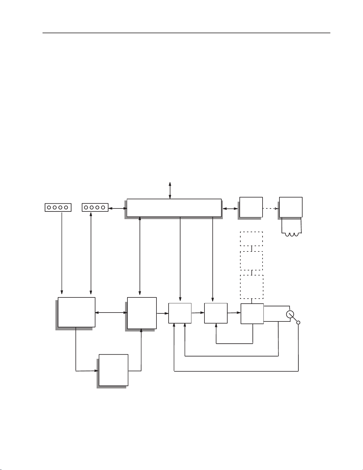
The Drive is a 3 phase full-wave power converter without flyback
rectifier, complete with a digital current regulator and a digital speed
regulator for armature voltage or speed regulation by tachometer
feedback. Shown in Figure 1.2 is a block diagram of the 1397 Drive.
The Drive employs wireless regulator construction and uses a keypad
for Drive setup, including parameter adjustments and unit selection,
monitoring, and diagnostics. Reference, feedback, and metering
signals can be interfaced to the Drive. The Drive can be controlled
locally by the control device (HIM, GPT, DriveTools etc.) keypad or
remotely by using the terminals at the regulator board terminal strip.
Figure 1.2
1397 Block Diagram
SCANPORT
DRIVE CONTROL SIGNALS
AND SEQUENCING
FIELD
CONTROL
FIELD
POWER
SUPPLY
DIGITAL
ANALOG &
FREQUENCY
INPUTS/OUTPUTS
OUTER
CONTROL
LOOP
(OCL)
SPEED
REFERENCE
SELECTION
AND
SCALING
SPEED
LOOP
CE Line
Inductor
CE Line
Filter
(Option)
Optional
Arm R–Gen
6 SCR
Power Unit
CURRENT
LOOP
6 SCR
POWER
UNIT
Armature
Current
Feedback
Armature Voltage Feedback
Speed Feedback
MOTOR FIELD
MOTOR
ARMATURE
ANALOG
TACH
OR
PULSE
ENCODER
Publication 1397-5.0 — June, 2001
Page 19
1–10 Introduction
БББББББББББББББ
Á
БББББББББББББББ
Á
Á
Á
БББББББББББББББ
Á
Á
БББББББББББББББ
Á
Á
Á
Á
Á
Á
Á
Á
Á
БББББББББББББББ
Á
Á
Á
Á
Á
Á
Á
Á
Á
Á
БББББББББББББББ
Á
Á
Á
Á
Á
Á
БББББББББББББББ
Á
Á
Á
Á
Á
Á
Á
Á
Á
БББББББББББББББ
Á
БББББББББББББББ
Á
Á
Á
БББББББББББББББ
БББББББББББББББ
Á
БББББББББББББББ
Á
Á
Á
Á
Á
БББББББББББББББ
Á
Á
Á
Á
Á
Á
БББББББББББББББ
Á
БББББББББББББББ
Á
Á
Á
БББББББББББББББ
Á
БББББББББББББББ
Á
Á
Á
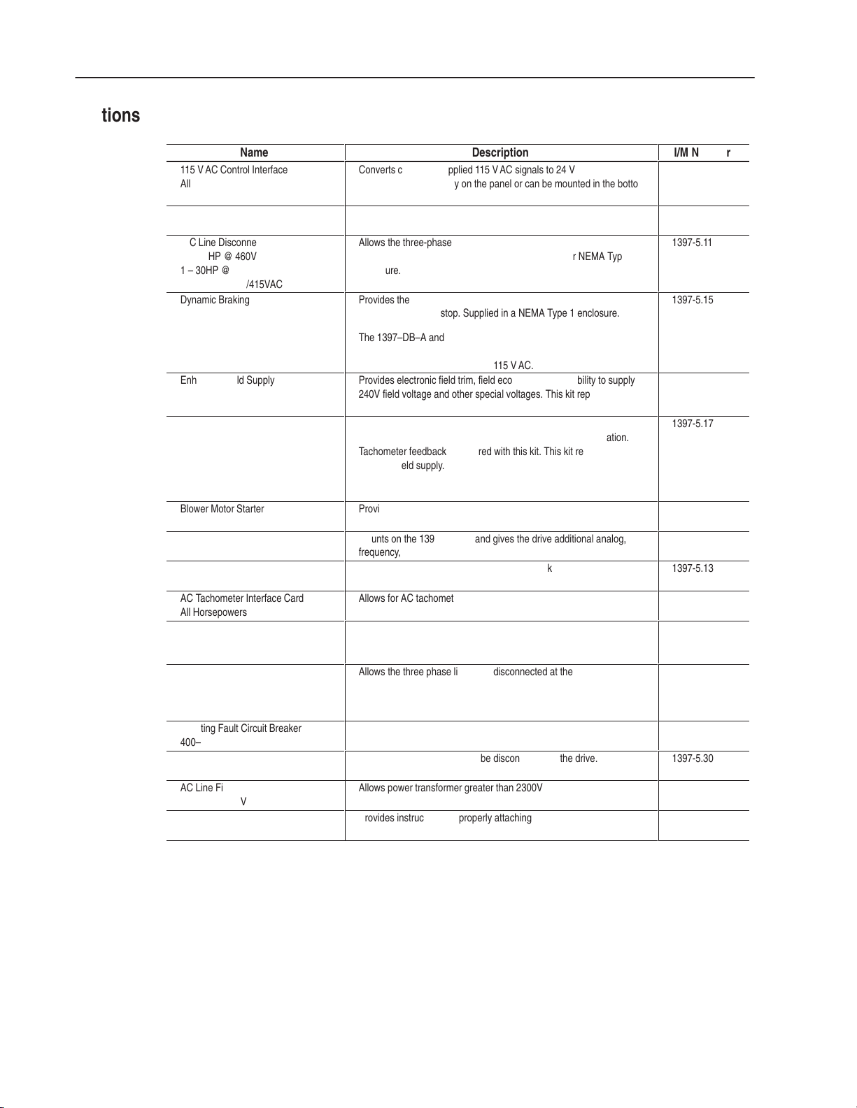
Options
Name
115 VAC Control Interface
All Horsepowers
ББББББББ
230 V AC Conversion
A-C Line Disconnect
ББББББББ
3 – 60 HP @ 460V
1 – 30HP @ 230V
ББББББББ
7 – 100A @ 380/415VAC
Dynamic Braking
ББББББББ
ББББББББ
ББББББББ
Enhanced Field Supply
ББББББББ
Regulated Field Supply
Supplied as standard on:
ББББББББ
400 – 600HP @ 460V
150HP @ 460V
ББББББББ
75 HP @ 230V and up
ББББББББ
265 & 521 ADC @ 380/415 VAC
Blower Motor Starter
Expansion I/O Module
ББББББББ
Pulse Encoder Interface Card
All Horsepowers
AC Tachometer Interface Card
All Horsepowers
AC Line Disconnect
ББББББББ
75 – 150 HP @ 460V
40 – 75 HP @ 230V
AC Line Disconnect
ББББББББ
200 – 300 HP @ 460V
100 – 150 HP @ 230V
ББББББББ
521 ADC @ 380/415 VAC
Inverting Fault Circuit Breaker
400–600 HP
AC Line Disconnect
ББББББББ
400 – 600 HP @ 460V
AC Line Filter Kit
600 HP @ 460V
Dynamic Braking Resistor Assembly
Lifting Instructions 250–600HP
ББББББББ
Description
Converts customer-supplied 115 V AC signals to 24 VDC for operating a
1397. Mounts separately on the panel or can be mounted in the bottom
БББББББББББББ
of a NEMA Type 1 enclosed drive.
Allows conversion of the 460 V AC 1397 to a 230 V AC 1397 at one-half
the 460 V AC horsepower rating.
Allows the three-phase line to be disconnected at the drive. Molded
БББББББББББББ
case switch that mounts on the chassis of the drive or NEMA Type 1
enclosure.
БББББББББББББ
Provides the hardware, including braking grids, needed to provide
dynamic braking on stop. Supplied in a NEMA Type 1 enclosure.
БББББББББББББ
The 1397–DB–A and 1397–DB–B series allow the kit to be panel
БББББББББББББ
mounted. These kits include the resistor grid assembly and contactor.
БББББББББББББ
The customer must supply fused 115 VAC.
Provides electronic field trim, field economy, and the ability to supply
240V field voltage and other special voltages. This kit replaces the
БББББББББББББ
standard field supply.
Provides field economy, as well as pre-weakening of the field using a
fixed reference or field weakening for above base speed operation.
БББББББББББББ
Tachometer feedback is required with this kit. This kit replaces the
standard field supply.
БББББББББББББ
БББББББББББББ
Provides a fused A-C starter with adjustable overload and interlocking
for control of three phase blower motor used to cool the DC motor.
Mounts on the 1397 chassis and gives the drive additional analog,
frequency, and digital I/O capability.
БББББББББББББ
Allows for digital pulse encoder speed feedback
Allows for AC tachometer speed feedback
Allows the three phase line to be disconnected at the drive.
БББББББББББББ
Allows the three phase line to be disconnected at the drive.
БББББББББББББ
БББББББББББББ
Allows high inertia loads on regenerative 1397 drives.
Allows the three phase line to be disconnected at the drive.
БББББББББББББ
Allows power transformer greater than 2300V RMS to be applied to the
drive.
Provides instructions for properly attaching and lifting Dynamic Braking
Kits.
БББББББББББББ
I/M Number
1397-5.18
ÁÁÁ
1397-5.16
1397-5.11
ÁÁÁ
ÁÁÁ
1397-5.15
ÁÁÁ
ÁÁÁ
ÁÁÁ
1397-5.24
ÁÁÁ
1397-5.17
ÁÁÁ
ÁÁÁ
ÁÁÁ
1397-5.20
1397-5.19
ÁÁÁ
1397-5.13
1397-5.22
1397-5.21
ÁÁÁ
1397-5.27
ÁÁÁ
ÁÁÁ
1397-5.29
1397-5.30
ÁÁÁ
1397-5.31
1397-5.32
ÁÁÁ
Publication 1397-5.0 — June, 2001
Page 20

Installation
Chapter 2
Chapter Objectives
Environment
The following data will guide you in planning the installation of the
1397 Drive. Since most start-up difficulties are the result of
incorrect wiring, every precaution must be taken to assure that the
wiring is done as instructed.
IMPORTANT: You are responsible for completing the installation,
wiring and grounding of the 1397 Drive and for complying with all
National and Local Electrical Codes.
ATTENTION: The following information is merely a
!
The Drive must be mounted in a clean, dry location. Contaminants
such as oils, corrosive vapors and abrasive debris must be kept out of
the enclosure. Temperatures around the Drive must be kept between
0° and 55°C (32°F and 131°F). Humidity must remain between 5%
to 95% non-condensing. The Drive can be applied at elevation of
3300 feet (1,000 meters) without derating. The Drive current rating
must be derated by 3% for each additional 1,000 feet (300 meters).
Above 10,000 feet (3,000 meters), consult the local Allen-Bradley
Sales Office.
guide for proper installation. The National Electrical
Code and any other governing regional or local code
will overrule this information. The Allen-Bradley
Company cannot assume responsibility for the
compliance or noncompliance to any code, national,
local or otherwise for the proper installation of this
Drive or associated equipment. A hazard of personal
injury and/or equipment damage exists if codes are
ignored during installation.
Mounting
The 1397 Drive is of the open chassis type construction and is
designed to allow you to install it in a suitable enclosure. The
selection of enclosure type is the responsibility of the user.
Dimensions and clearances for the 1397 are detailed in the figures on
the following pages.
ATTENTION: Plan Drive installation so that all
!
cutting, drilling, tapping and welding can be done with
the Drive removed from the enclosure. The Drive is of
the open type construction and any metal debris must
be kept from falling into the Drive. Metal debris or
other foreign matter may become lodged in the
circuitry resulting in component damage.
Publication 1397-5.0 — June, 2001
Page 21

2–2 Installation
)
Cooling Airflow
Line Filters (CE Only)
AC Line Inductors (CE Only
In order to maintain proper cooling, the Drive must be mounted in a
vertical position. Refer to Figure 2.1 for the recommended minimum
clearance of each Drive.
The Drive design produces up to a 10°C or 18°F air temperature rise
when the Drive is operated at full capacity. Precautions should be
taken not to exceed the maximum inlet ambient air temperature of
55°C (131°F). If the Drive is in an enclosed cabinet, air circulation
fans or a closed circuit heat exchanger may be required.
For information on installing, wiring and grounding Line Filters used
in CE compliant applications, refer to Appendix B.
For installation information on AC Line Inductors used in CE
compliant applications, refer to Appendix B.
Publication 1397-5.0 — June, 2001
Page 22
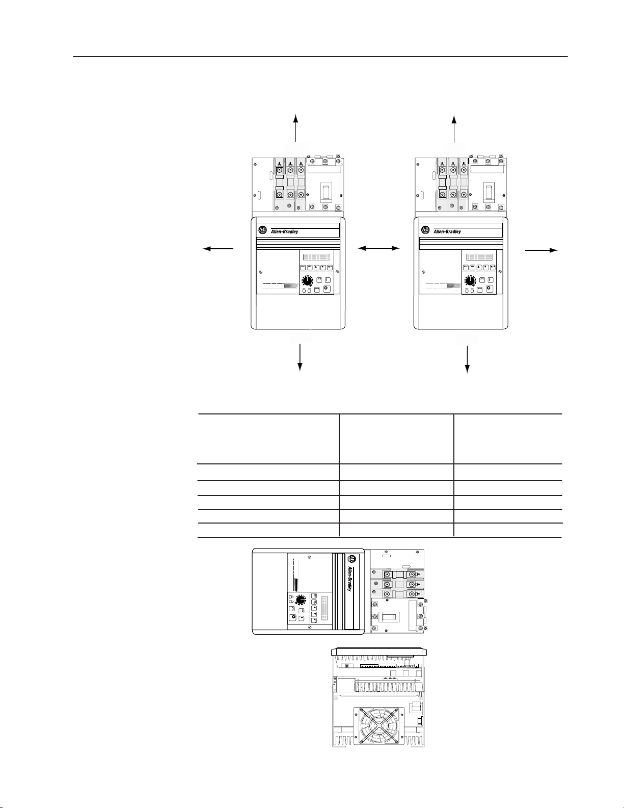
Figure 2.1
Enclosure Mounting Minimum Clearances
2–3Installation
E
A
D
Approved Mounting Methods
All Dimensions Millimeters and (Inches)
Enclosure Mounting Clearances
A Leftside Clearance
B Rightside Clearance
C Drive to Drive Side Clearance
D Bottom Clearance
E Top Clearance
C
1.5 – 30 HP @ 230VAC
3 – 60 HP @ 460VAC
7 – 110A @ 380 / 415 VAC
76 mm (3 in.)
51 mm (2 in.)
101 mm (4 in.)
127 mm (5 in.)
127 mm (5 in.)
E
B
D
40 – 150 HP @ 230VAC
75 – 600 HP @ 460VAC
265A @ 380 / 415 VAC
76 mm (3 in.)
51 mm (2 in.)
101 mm (4 in.)
305 mm (12 in.)
305 mm (12 in.)
NOT APPROVED
Note: Do Not Mount
Drive Horizontally
on Side or Back.
Publication 1397-5.0 — June, 2001
Page 23
2–4 Installation
Enclosure Mounting
Dimensions
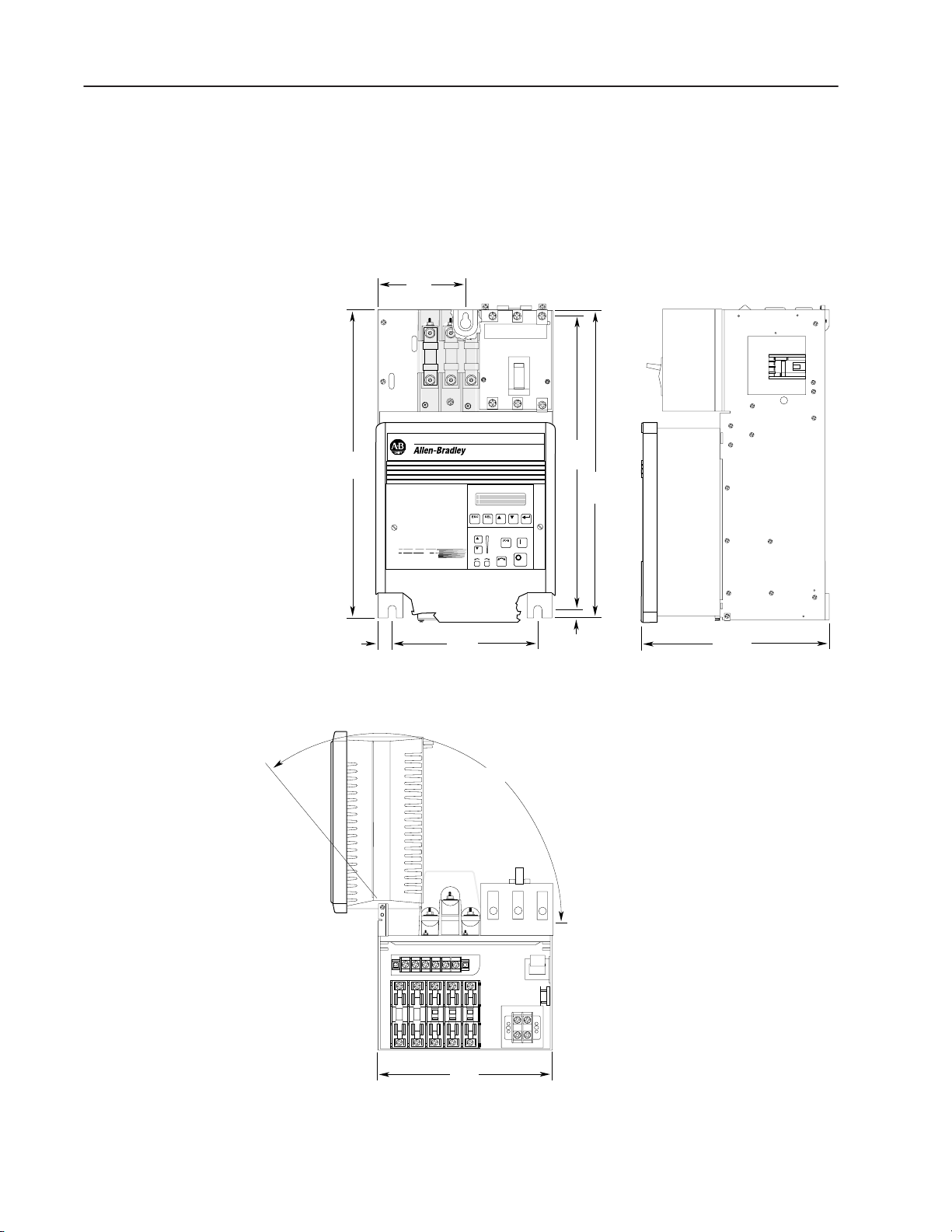
Figure 2.2
Drive Mounting Dimensions –
1.5 to 30 HP at 230 VAC
7 to 110A @ 380/415 VAC
3 to 60 HP at 460 VAC
136.0
(5.35)
477.5
(18.80)
22.5
(0.89)
225.0
(8.86)
FRONT
135˚
463.0
(18.23)
7.0
(0.28)
497.5
(19.59)
300.0
(11.81)
SIDE
Publication 1397-5.0 — June, 2001
270.5
(10.65)
TOP
Rec Hardware
3 x M6 or 1/4”
All Dimensions Millimeters and (Inches)
Approximate Shipping Weight 30.8 kg (68 lbs.)
Page 24
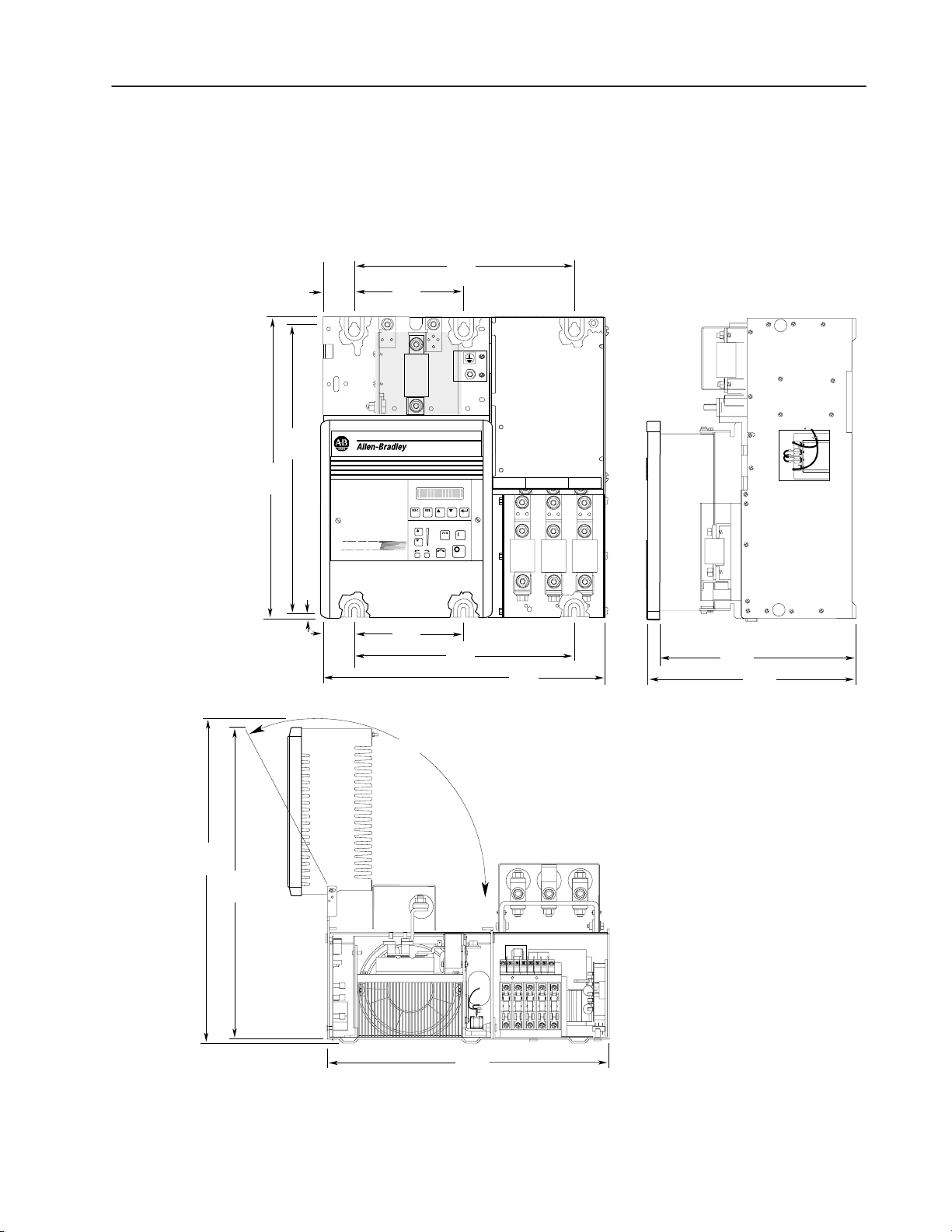
491.8
(19.36)
464.6
(18.29)
37.5
(1.48)
Figure 2.3
Drive Mounting Dimensions –
40 to 75 HP at 230 VAC
265A @ 380/415 VAC
75 to 150 HP at 460 VAC
375.0
(14.76)
200.0
(7.87)
45
A1
GRD
181 182
2–5Installation
P4
P4
S4
P4
S4
S4
183
531.7
(20.93)
509.5
(20.06)
16.8
(0.66)
37.5
(1.48)
200.0
(7.87)
135˚
375.0
(14.76)
FRONT
461.6
(18.17)
TOP
461.6
(18.17)
300.0
(11.81)
334.3
(13.16)
SIDE
Rec Hardware
6 x M8 or 5/16”
All Dimensions Millimeters and (Inches)
Approximate Shipping Weight 55.0 kg (122 lbs.)
Publication 1397-5.0 — June, 2001
Page 25
2–6 Installation
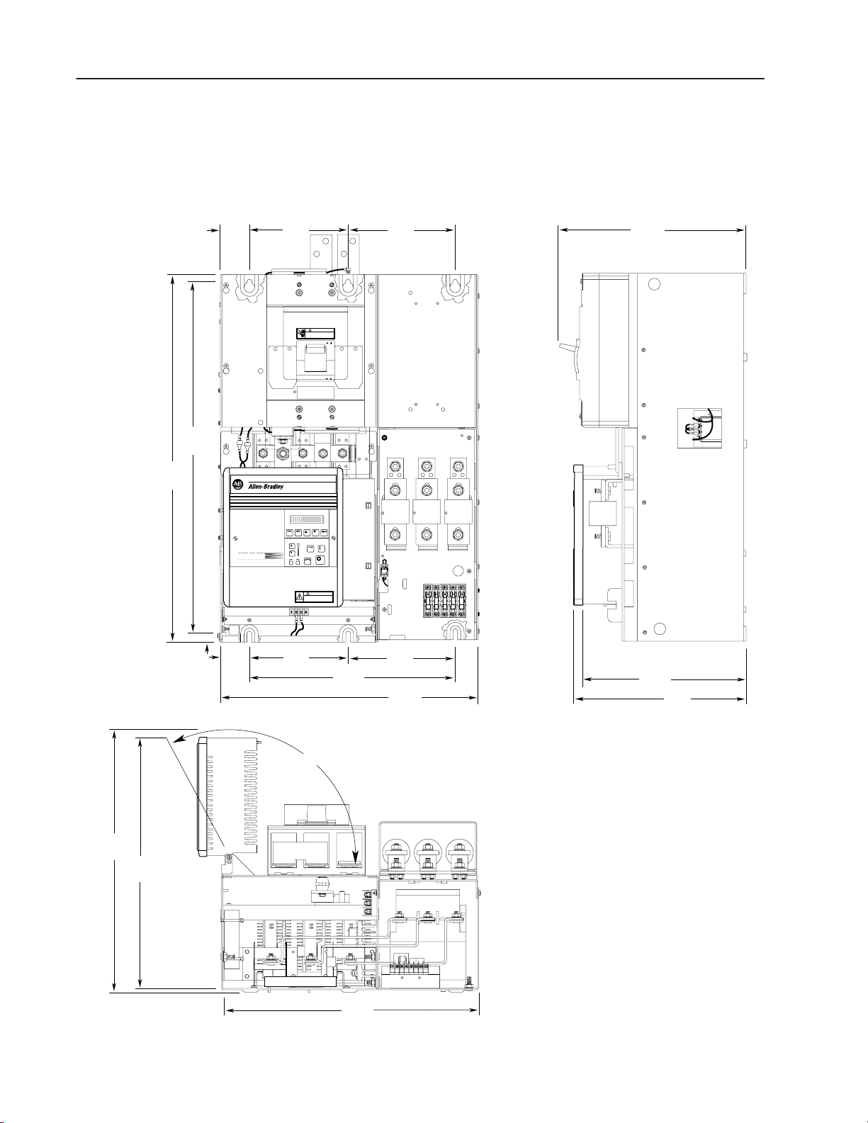
(2.66)
822.8
(32.39)
850.0
(33.46)
67.5
230.0
(9.06)
Figure 2.4
Drive Mounting Dimensions – 150 HP at 230 VAC;
200 – 300 HP at 460 VAC
599.0
(23.58)
240.0
(9.45)
DANGER
CIRCUIT BREAKER DOES NOT DISCONNECT INCOMING A0
LINE POWER IT ONLY PROVIDES DC FAULT PROTECTION.
LE DISCONECTEUR NE COUPTE PAS L'AUTOMENTATION DU SPOTEUR IL NES
810903-2424
SERT QUE A ASSURER UNE PROTECTION CONTRE LES DESFAULTS DC.
424.7
(16.72)
598.4
(23.56)
578.9
(22.79)
12.7
(0.50)
GND
TORQUE
14-10GA 35 LB.-IN
0 GA 48 LB.-IN.
SPEC
67.5
(2.66)
!
DANGER
RISK OF ELECTRICAL SHOCK. DISCONNECT INPUT
POWER BEFORE SERVICING EQUIPMENT.
P/N 33145
.
230.0
(9.06)
470.0
(18.50)
FRONT
240.0
(9.45)
599.0
(23.58)
371.1
(14.61)
406.0
(15.99)
SIDE
135˚
599.0
(23.58)
TOP
Approximate Shipping Weight 100 kg (220.5 lbs.)
Mounting Hardware
6 x M10 or 3/8”
All Dimensions Millimeters and (Inches)
Publication 1397-5.0 — June, 2001
Page 26

Figure 2.5
Drive Mounting Dimensions –
400 to 600 HP at 460 VAC
2–7Installation
45.25"
(1149.2mm)
(1104.0mm)
43.47"
2.12"
(53.8mm)
42.37"
(1076.3mm)
2.12"
(53.8mm)
10.20"
(259.1mm)
10.20"
(259.1mm)
26.68"
(677.7mm)
(261.6mm)
(261.6mm)
10.30"
81 82 83
1FU 2FU 3FU
281 282 283
BLOWER MOTOR
STARTER KITS
10.30"
18.82"
(478.1mm)
ON
OFF
5FU4FU
288 289
18.30"
(464.7mm)
25.61"
(650.5mm)
Publication 1397-5.0 — June, 2001
Page 27

2–8 Installation
Grounding Procedures
The purpose of grounding is to:
• Limit dangerous voltages to ground potential on exposed parts in
the event of an electrical fault.
• To facilitate proper operation of overcurrent device when ground
fault conditions are incurred.
• To provide suppression of electrical interference.
The general grounding concept for the 1397 is shown in Figure 2.6
and explained below. Specific Drive ground point locations are
detailed in Figures 2.7, 2.8 and 2.9.
Safety Ground – Is the safety ground required by code. The
ground bus can be connected to adjacent building steel (girder, joist)
or a floor ground grid, provided grounding points comply with NEC
regulations. Multiple connections are permitted, but Do Not ground
at the same point as a Signal Ground. The minimum distance
between Signal and Safety Ground is 10 feet (3 meters). The ground
bus is limited to a maximum of 1 ohm resistance to ground.
Power Feeder – Each power feeder from the substation transformer
to the Drive must be provided with properly sized ground cables.
Simply utilizing the conduit or cable armor as a ground is not
adequate. The conduit or cable armor and ground wires should be
bonded to substation ground at both ends. Each transformer
enclosure and/or frame must be bonded to ground at a minimum of
two locations.
Motor Connection – Each DC motor frame must be bonded to
grounded building steel within 20 feet (6 meters) of its location and
tied to the drives Safety Ground via ground wires within the power
cables and/or conduit. Bond the conduit or cable armor to ground at
both ends. The ground wire size and installation must be per NEC
Article 250.
Encoder Connections – If used, must be routed in grounded steel
conduit. The conduit must be grounded at both ends. Ground the
cable shield at the motor only (See Figure 2.6).
Tachometer Connections – If used, must be routed in grounded
steel conduit. The conduit must be grounded at both ends. Ground
the cable shield at the Drive end Only (See Figure 2.6).
(CE) Line Filter Connections – For grounding reqirements in CE
compliant applications, refer to page B.8 in this manual.
(CE) AC Line Inductor Connections – For grounding reqirements
in CE compliant applications, refer to page B.8 in this manual.
Publication 1397-5.0 — June, 2001
Page 28
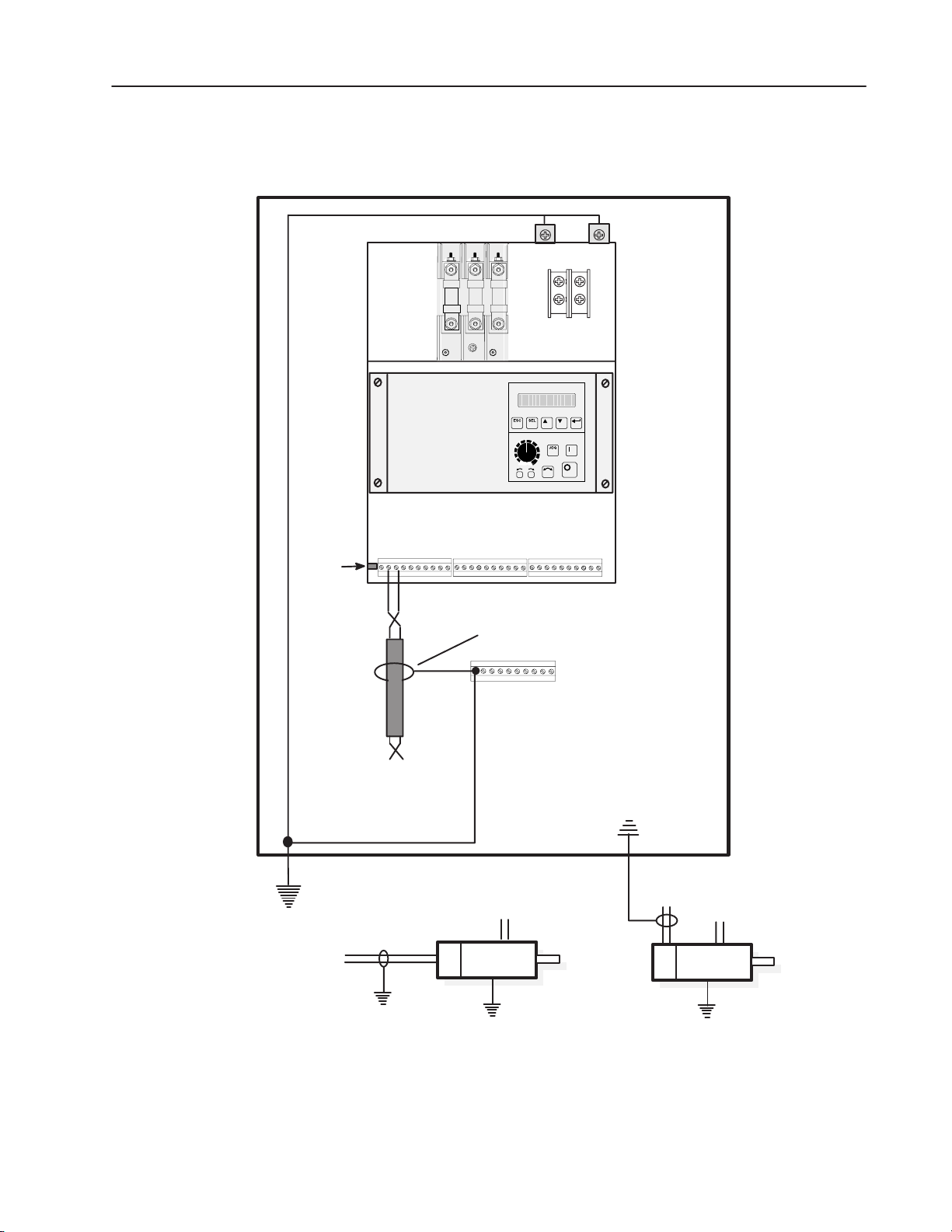
Figure 2.6
1397 Grounding Practices
A1 45
Safety
Ground
Studs
2–9Installation
Control
Ground
Stud
(Located
behind
swing out
panel)
GROUND STUD
(BUS)
A
B
+ –
Twisted
Pair
DC Encoder
Regulator Board
Terminal Strip
Ground shield to terminal strip
Customer supplied terminal strip
mounted in close proximity to Drive
to keep shield length to a minimum.
+ –
Motor
DC Tach
Tach cable in steel conduit
(Grounded – wiring Class 8)
+ –
+ –
Motor
IMPORTANT: For CE requirements refer to Appendix B
Publication 1397-5.0 — June, 2001
Page 29
2–10 Installation
CONTROL GROUND
POINTS (on bottom
left side of drive)
M5 with Lug
Figure 2.7
Drive Ground Point Locations – 1.5-30 HP at 230 VAC
7–100 A @ 380/415 VAC
3-60 HP at 460 VAC
POWER
GROUND
TOP VIEW
M6 with Lug
POINTS
Publication 1397-5.0 — June, 2001
Page 30
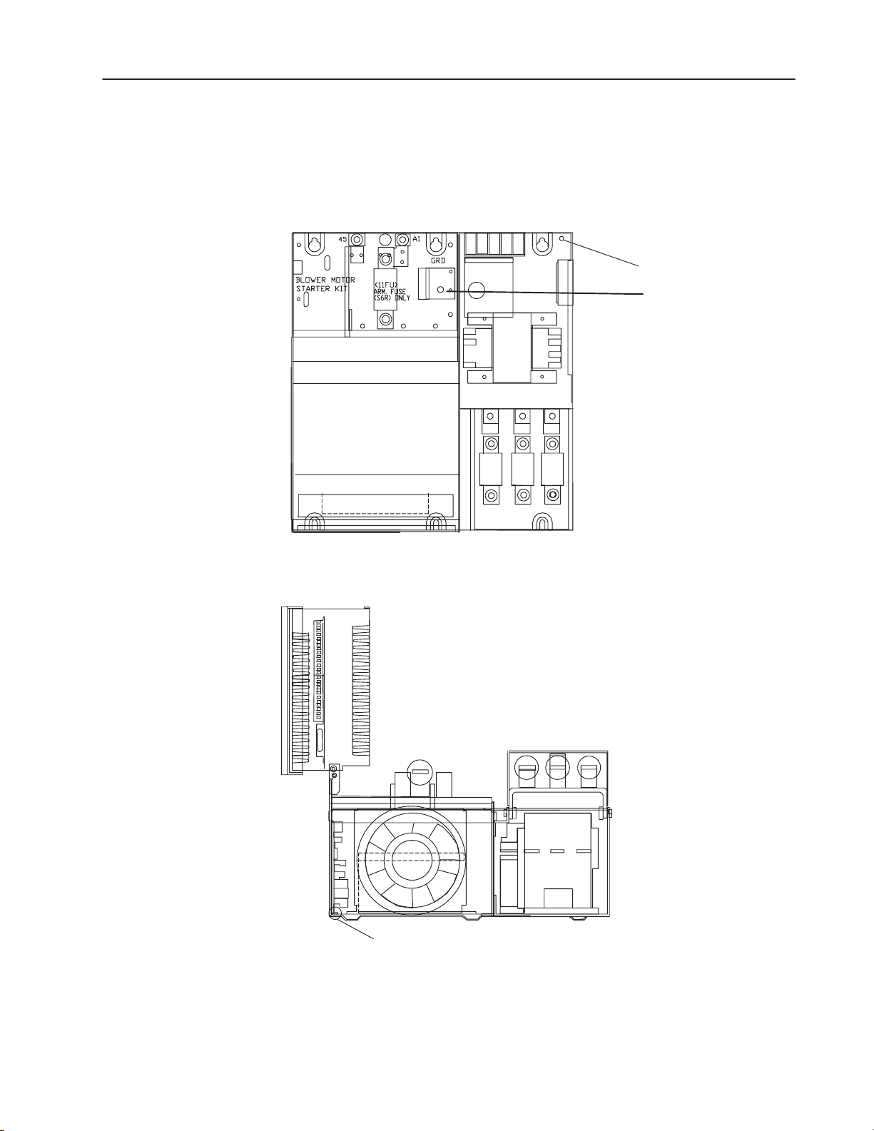
Figure 2.8
Drive Ground Point Locations – 40-75 HP at 230 VAC
265A @ 380/415 VAC
75-150 HP at 460 VAC, 265 Amp Rated Output
POWER
GROUND POINT
M8
2–11Installation
FRONT VIEW OF DRIVE
WITHOUT DISCONNECT
BOTTOM VIEW
CONTROL GROUND POINT
M6 With Lug
Publication 1397-5.0 — June, 2001
Page 31

2–12 Installation
Figure 2.9
Drive Ground Point Locations – 150 HP at 230 VAC;
300 HP at 460 VAC
10mm DIA
GROUND STUD
Located at back of chassis
6mm DIA
CONTROL
GROUND
14-10GA 35 LB.-IN
0 GA 48 LB.-IN.
GND
TORQUE
.
SPEC
STUD
45
DANGER
CIRCUIT BREAKER DOES NOT DISCONNECT INCOMING A0
LINE POWER IT ONLY PROVIDES DC FAULT PROTECTION.
LE DISCONECTEUR NE COUPTE PAS L'AUTOMENTATION DU SPOTEUR IL NES
SERT QUE A ASSURER UNE PROTECTION CONTRE LES DESFAULTS DC.
!
DANGER
RISK OF ELECTRICAL SHOCK. DISCONNECT INPUT
POWER BEFORE SERVICING EQUIPMENT.
FRONT
10mm DIA
GROUND STUDS
A1
Located at back of chassis
810903-2424
P/N 33145
SIDE
Publication 1397-5.0 — June, 2001
10mm DIA
GROUND STUD
TOP
10mm DIA
GROUND STUD
10mm DIA
GROUND STUD
(With Lug)
Page 32

Figure 2.10
34 PIN
60 PIN
Drive Ground Point Locations –
400-600 HP at 460 VAC
2–13Installation
M10 GROUND STUD
1FU
BLOWER MOTOR
STARTER KITS
182181 183
2FU 3FU
282281
283
4FU
288
M10 GROUND STUD
TOP VIEW
5FU
289
M6 CONTROL GROUND STUD
M6 CONTROL GROUND STUD
BOTTOM VIEW
Publication 1397-5.0 — June, 2001
Page 33

2–14 Installation
Table 2.A
Chassis Ground Connections
Hardware Size Tightening
M5 18 lb/in (2Nm)
M6 33 lb/in (3.7 Nm)
M8 100 lb/in (11.3 Nm)
M10 200 lb/in (23 Nm)
Lug with 14–10 AWG 35 lb/in (4 Nm)
Lug with 8 AWG 40 lb/in (4.5 Nm)
Lug with 6–4 AWG 45 lb/in (5.1 Nm)
Wiring Clearance
Disconnect
Although the minimum clearance should be maintained for proper
cooling, this space may not always provide proper wiring clearance.
The minimum allowable wire bending radius may necessitate that
extra space be provided to accommodate power wiring. Consult the
governing code for the proper wiring method.
NOTE: You are responsible for completing the installation of the
Drive system and to comply with all National and Local Electrical
Codes. The following information is to be used as a reference only.
ATTENTION: Hazard of electric shock or equipment
!
damage exist if the Drive is not installed correctly. The
National Electrical Code (NEC) and local codes outline
provisions for safely installing electrical equipment.
Installation must comply with specifications regarding
wire types, conductor sizes, branch circuit protection
and disconnect devices. Failure to do so may result in
personal injury and/or equipment damage.
You must provide a main disconnect and lockout device with cabinet
interlocks. This device must be wired in the isolation transformer or
reactor primary circuit. The device must be sized to handle 115% of
the full load primary current plus any additional loads that are
connected to the control system. Proper branch circuit protection for
the Drive and additional devices must be provided according to NEC
and local codes.
24V Power Supply
Publication 1397-5.0 — June, 2001
NOTE: Refer to Table on Page 1-6 for Drive current ratings to aid
in properly sizing wire.
The 1397 is equipped with a 250mA 24V power supply to power
additional peripheral devices. For example, up to two of the following
24V DC Scanport modules can be used:
1203-GK1 Single Point Remote I/O
1203-GK2 DFI (RS–232 / 422 / 485) or DH–485
Page 34

2–15Installation
If more than two SCANport modules are used with the 1397 Drive,
an additional 24V DC power supply must be installed, or 115V
SCANport modules must be used. Refer to the SCANport user
manual for information on installing additional SCANport modules.
The 24V DC power supply can be accessed at terminals #14 (24V
DC) and #15 (24VDC common) of the regulator board terminal strip.
Wire Size, Type & Class
14
15
+24V
24V COM
24V DC Power Supply
Wire sizes must be selected individually, observing all applicable
safety and NEC regulations. The minimum permissible wire size
does not necessarily result in the best operating economy. Due to the
Drive overload capacity, the conductors for the transformer primary
and secondary must be sized (at a minimum) for 125% of the full
load Drive line current. The motor armature conductors must also be
rated for 125% (at a minimum) of the full load motor current.
Shielded type wire is recommended in control circuits for protection
against interference. A shielded wire is required for all signal wires.
The recommended conductor size must be a minimum of 24 AWG.
The best interference suppression is obtained with a wire having an
individual shield for every pair. Table 2.B provides a listing and
description of cable types and wiring recommendations. Figure 2.9
shows recommended cable shielding. Note that wiring classes are
for reference only, and are not associated with any code or standard.
Terminal;
Symbol
Figure 2.11
Cable Shielding Recommendations
Shield
Shield
Shield
Shield Connection
2 Conductor
Shielded Cable
2 Conductor Shielded Cable
Multi-Conductor Shielded
Cable with Individual
Shielded Pairs
Publication 1397-5.0 — June, 2001
Page 35

2–16 Installation
Table 2.B
Cable and Wiring Recommendations
Category
Power
Control
Signal
(Process)
Signal
(Comm)
Wiring
Class
1
2
3
4
5
6
7
8
9
11
Signal Definition
AC Power (600V or greater)
AC Power (less than 600V)
DC Power
DC Power
115V AC/DC Logic
115V AC Power
24V AC/DC Logic
Analog Signals,
DC Supplies
Digital (low speed)
Digital
(high speed)
Serial
Communication
Serial Communication
(greater than 20k baud)
Signal Examples
2.3kV 3/Ph AC Lines
460V 3/Ph AC Lines
DC Motor Armature
DC Motor Field
Relay Logic/PLC I/O
Motor Thermostat
Power Supplies,
Instruments
PLC I/O
Reference/Feedback
Signal, 5 to 24V DC
TTL
I/O, Encoder, Count
Pulse Tach
RS-232, 422 to
Terminals/Printers
PLC Remote I/O,
PLC Data Highway
Cable Type
per NEC & Local Codes
per NEC & Local Codes
per NEC & Local Codes
per NEC & Local Codes
per NEC & Local Codes
per NEC & Local Codes
Shielded Cable – Belden
8735, 8737, 8404
Shielded Cable – Belden
9728, 9730
Shielded Cable – Belden
RS-232 – 8735, 8737
RS-422 – 9729, 9730
Twinaxial Cable – Belden
9463, A-B 1770-CD
Minimum Spacing in Inches between Classes –
1
0
3/9
3/9
3/
18
2/3/4
3/9
0
3/6
3/
12
Steel Conduit/Tray
7/8
3/18
3/12
3/9
0
9/10/11
Note6
Note 6
Note 6
1/3
5/6
3/9
3/6
0
3/9
Spacing
Notes
1/2/5
1/2/5
1/2/5
2/3/4/5
Note 6 1/3 0
Example: Spacing relationship between 480V AC incoming power leads and 24V DC logic leads.
– 480V AC leads are Class 2 ; 24V DC leads are Class 6
– For separate steel conduits, the conduits must be 3 inches (76 mm) apart
– In a cable tray, the two groups of leads are to be 6 inches (152 mm) apart
Spacing Notes:
1. Both outgoing and return current carrying conductors are to be pulled
in same conduit or laid adjacent in tray.
2.
Cables of the following classes can be grouped together.
A. Class 1; Equal to or above 601 volts
B. Classes 2,3, and 4 may have their respective circuits pulled in the
same conduit or layered in the same tray.
C. Classes 5 and 6 may have their respective circuits pulled in the
same conduit or layered in the same tray.
Note: Bundle may not exceed conditions of NEC 310
D. Classes7 and 8 may have their respective circuits pulled in the
same conduit or layered in the same tray.
Note: Encoder cables run in a bundle may experience some
amount of EMI coupling. The circuit application may dictate
separate spacing.
E. Classes 9, 10 and 11 may have their respective circuits pulled in
the same conduit or layered in the same tray.
Communication cables run in a bundle may experience some
amount of EMI coupling and corresponding communication faults.
The application may dictate separate spacing.
3. All wires of class 7 thru 11 MUST be shielded per the
recommendations
4. In cable trays, steel separators are advisable between the class
groupings.
5. If conduit is used, it must be continuous and composed of magnetic
steel.
6. Spacing of communication cables classes 2 thru 6 is:
CONDUIT SPACING THRU AIR
115 Volts – 1 inch 115 Volts – 2 inches
230 Volts – 1.5 inches 230 Volts – 4 inches
380/575 Volts – 3 inches 380/575 Volts – 8 inches
575 volts – proportional to 6” 575 volts proportional to 12”
per 1000 volts. per 1000 volts
General Notes
1. Steel conduit is recommended for all wiring classes. (Classes 7-11).
2. Spacing shown between classes is the minimum required for parallel
runs less than 400 feet. Greater spacing should be used where
possible.
3. Shields for shielded cables must be connected at one end only. The
other end should be cut back and insulated. Shields for cables from a
cabinet to an external device must be connected at cabinet end.
Shields for cables from one cabinet to another must be connected at
the source end cabinet. Splicing of shielded cables, if absolutely
necessary, should be done so that shields remain continuous and
insulated from ground.
4. Power wire is selected by load. 16AWG is the minimum
recommended size for control wiring.
LEGEND
2/3/4
3/9
Class Spacing
Steel Conduit/Tray
Publication 1397-5.0 — June, 2001
Page 36

2–17Installation
Motor Installation
The following procedure provides the steps needed to properly
install a DC motor for use with a 1397 Drive.
1. Verify that the motor you intend to install is the appropriate
rating for use with your model 1397 Drive.
2. Install the DC motor in accordance with the motor
manufacturer’s installation instructions.
3. Ensure that coupled applications have proper shaft alignment
with the driven machine or that belted applications have proper
sheave/belt alignment to minimize unnecessary motor loading.
4. If the motor is accessible while it is running, make certain all
guards necessary to satisfy local and national codes are
installed.
5. Size the motor armature circuit conductors for the specific
Drive rating and according to applicable codes.
6. Locate and connect the DC motor armature leads and the shunt
field supply leads on the Drive (Figures 2.13 through 2.16).
ATTENTION: 400 to 600 HP @ 460VAC
!
Regenerative Drives require an externally mounted
Inverting Fault Protection device connected in the
armature circuit. Refer to the instruction manual
provided with the Inverting Fault Protection device you
have selected for your drive for connection information.
Failure to provide Inverting Fault Protection could
result in severe bodily injury or loss of life.
Power Wiring Procedure
The following procedure provides the steps needed to properly
perform the power wiring connections to the 1397 Drive.
Using Table 2.C, verify that the motor field is compatible with the
DC field voltage output of the Drive.
Table 2.C
Standard Field Voltage Output
AC Incoming
Voltage to Drive
230V AC
380V AC
415V AC
460V AC
DC Supply Output
Voltage to Field
150V DC
250V DC
270V DC
300V DC
Publication 1397-5.0 — June, 2001
Page 37

2–18 Installation
1. Connect the motor armature and field leads to produce proper
direction of motor rotation. Figure 2.12 shows the connections
required to produce counterclockwise rotation of the motor
when viewed from the commutator end with a positive speed
reference input to the Drive.
Figure 2.12
Typical DC Motor Connections (CCW) Rotation
1.5 to 150HP @ 230VAC, 3 to 300HP @ 460VAC
Bulletin 1397
A2/S1–S2
Link
Removed
Bulletin 1397
F1 ( + )
A1
( – ) 45
F2 ( – )
F1 ( + )
( 2 )
A1
A2
( 2 )
S1
S2
F2 ( – )
Motor
Basic Stabilized Shunt Machine,
CCW Rotation, Facing Commutator End
F1 ( + )
DBR
A2/S1
A1
S1
*
F2 ( – )
F1 ( + )
A1
A2
S1
S2
F2 ( – )
Motor
(1)
400 to 600HP @ 460VAC
( 2 )
( 2 )
(1)
Bulletin 1397
Straight Shunt Machine,
CCW Rotation, Facing Commutator End
A2/S1–S2
Link
Installed
A2/S1
Bulletin 1397
F1 ( + )
( – ) 45
F2 ( – )
F1 ( + )
S1
DBR
F2 ( – )
A1
A1
F1 ( + )
( 2 )
A1
A2
( 2 )
A2
F2 ( – )
(1)
Motor
F1 ( + )
( 2 )
A1
A2
F2 ( – )
Motor
( 2 )
(1)
*
( 3 )
Basic Stabilized Shunt Machine,
CCW Rotation, Facing Commutator End
*If Used
Straight Shunt Machine,
CCW Rotation, Facing Commutator End
(1) In cases where full regenerative torque capability is required for braking or slow down operation or where the drive
will be applied for bi–directional operation, you should specify straight shunt DC motors (wound without a series field winding)
to assure symmetrical motor operation in both forward and reverse directions, full torque capability, and motor stability under
any mode of operation.
(2) If this connection of the motor armature leads results in motor rotation opposite of what is required, reverse the A1 and A2
lead connections at the motor.
(3) Connect Drive Terminal A2/S1 or S2 to motor terminal A2.
2. The 1397 is supplied with semi conductor fuses for line
protection. An isolation transformer can also be used. In
general, the 1397 is suitable for direct connection to a correct
voltage AC line that has minimum impedance of 3%. If the
Publication 1397-5.0 — June, 2001
Page 38

2–19Installation
line is lower impedance, a line reactor or isolation transformer
must be added upline from the Drive to increase line
impedance. If the line impedance is too low, transient voltage
spikes or interruptions can create excessive current spikes that
will cause nuisance input fuse blowing, and may cause damage
to the Drive power structure. Refer to Figures 2.13 through
2.16 for AC input wiring at the main fuses and the
following ATTENTION note when determining if a line reactor
or isolation transformer is required for your installation.
AC Line Connection – Connect incoming three-phase AC line
power to the AC Line Terminals as shown in Figures 2.13 through
2.16. Note that the incoming AC power is wired to separate
terminals on the 1.5-30HP/3-60HP, 7–110A Drives, but is wired
directly to AC line fuses on 40-75HP/75-150HP,
100-150/200-300HP, 265A and higher and 400 to 600 HP Drives.
The fuses supplied are designed to provide protection against short
circuits for the Drive semiconductors and associated output wiring.
They are not to be considered a substitute for the user supplied motor
branch circuit protective devices that are required by the National
Electrical Code. Refer to Table 2.E for proper sizing of the AC
power and branch fuses.
ATTENTION: If the AC input power system does not
!
have a neutral or one phase referenced to ground, an
isolation transformer with the neutral of the secondary
grounded is highly recommended. If the line-to-line
voltages on any phase can exceed 125% of the nominal
line-to-line voltage, an isolation transformer with the
neutral of the secondary grounded, is always required.
Failure to observe these precautions could result in
bodily injury or damage to equipment.
Publication 1397-5.0 — June, 2001
Page 39

2–20 Installation
Figure 2.13
AC Line Connection Location
1.5-30 HP at 230 VAC; 3-60 HP at 460 VAC
7-110A @ 380/415 VAC
AC Line
Connection
FRONT
181
(L1)
AC Line
Connection
182
(L2)
183
(L3)
FRONT
81
(L1)
82
(L2)
83
(L3)
Without AC Line Disconnect
Publication 1397-5.0 — June, 2001
With AC Line Disconnect
Page 40

Figure 2.14
AC Line Connection Location
40-75 HP at 230 VAC; 75-150 HP at 460 VAC
265A @ 380/415 VAC
2–21Installation
AC Line
Connection
FRONT VIEW OF DRIVE WITHOUT DISCONNECT
Publication 1397-5.0 — June, 2001
Page 41

2–22 Installation
Figure 2.15
A-C Line Connection Locations
100-150 HP at 230 VAC; 200-300 HP at 460 V AC
14-10GA 35 LB.-IN
0 GA 48 LB.-IN.
DANGER
CIRCUIT BREAKER DOES NOT DISCONNECT INCOMING A0
LINE POWER IT ONLY PROVIDES DC FAULT PROTECTION.
LE DISCONECTEUR NE COUPTE PAS L'AUTOMENTATION DU SPOTEUR IL NES
810903-2424
SERT QUE A ASSURER UNE PROTECTION CONTRE LES DESFAULTS DC.
!
DANGER
RISK OF ELECTRICAL SHOCK. DISCONNECT INPUT
POWER BEFORE SERVICING EQUIPMENT.
P/N 33145
GND
TORQUE
.
SPEC
AC Line
Connection
SHOWN WITHOUT
AC LINE
DISCONNECT
Publication 1397-5.0 — June, 2001
Page 42

Figure 2.16
A-C Line Connection Locations
400-600 HP at 460 VAC
AC LINE
CONNECTION
AC LINE
CONNECTION
2–23Installation
81 82 83
ON
BLOWER MOTOR
STARTER KITS
Without AC
Line Disconnect
1FU
281
182181 183
2FU 3FU
282
283
4FU
288
OFF
1FU 2FU 3FU
282
281
5FU
289
BLOWER MOTOR
STARTER KITS
283
5FU4FU
288 289
With AC
Line Disconnect
Publication 1397-5.0 — June, 2001
Page 43

2–24 Installation
HP
1.5
2
3
5
7.5
10
15
20
25
30
40
50
60
75
100
125
150
200
250
300
400
500
600
Table 2.D
AC Line Connectors
Recommended Tightening Torque
230 V AC 380 VAC 415 VAC 460 V AC
6.2 Nm (55 lb-in)
6.2 Nm (55 lb-in)
6.2 Nm (55 lb-in)
6.2 Nm (55 lb-in)
6.2 Nm (55 lb-in)
6.2 Nm (55 lb-in)
13.6 Nm (120 lb-in)
13.6 Nm (120 lb-in)
13.6 Nm (120 lb-in)
13.6 Nm (120 lb-in)
22 Nm (200 lb-in)
22 Nm (200 lb-in)
22 Nm (200 lb-in)
22 Nm (200 lb-in)
22 Nm (200 lb-in)
40 Nm (350 lb-in)
40 Nm (350 lb-in)
—
—
—
—
—
6.2 Nm (55 lb-in)
6.2 Nm (55 lb-in)
6.2 Nm (55 lb-in)
6.2 Nm (55 lb-in)
6.2 Nm (55 lb-in)
6.2 Nm (55 lb-in)
6.2 Nm (55 lb-in)
6.2 Nm (55 lb-in)
13.6 Nm (120 lb-in)
13.6 Nm (120 lb-in)
13.6 Nm (120 lb-in)
13.6 Nm (120 lb-in)
22 Nm (200 lb-in)
22 Nm (200 lb-in)
22 Nm (200 lb-in)
22 Nm (200 lb-in)
22 Nm (200 lb-in)
6.2 Nm (55 lb-in)
6.2 Nm (55 lb-in)
6.2 Nm (55 lb-in)
6.2 Nm (55 lb-in)
6.2 Nm (55 lb-in)
6.2 Nm (55 lb-in)
6.2 Nm (55 lb-in)
6.2 Nm (55 lb-in)
13.6 Nm (120 lb-in)
13.6 Nm (120 lb-in)
13.6 Nm (120 lb-in)
13.6 Nm (120 lb-in)
22 Nm (200 lb-in)
22 Nm (200 lb-in)
22 Nm (200 lb-in)
22 Nm (200 lb-in)
22 Nm (200 lb-in)
—
—
6.2 Nm (55 lb-in)
6.2 Nm (55 lb-in)
6.2 Nm (55 lb-in)
6.2 Nm (55 lb-in)
6.2 Nm (55 lb-in)
6.2 Nm (55 lb-in)
6.2 Nm (55 lb-in)
13.6 Nm (120 lb-in)
13.6 Nm (120 lb-in)
13.6 Nm (120 lb-in)
13.6 Nm (120 lb-in)
22 Nm (200 lb-in)
22 Nm (200 lb-in)
22 Nm (200 lb-in)
22 Nm (200 lb-in)
22 Nm (200 lb-in)
34 Nm (300 lb-in)
34 Nm (300 lb-in)
34 Nm (300 lb-in)
34 Nm (300 lb-in)
34 Nm (300 lb-in)
Note: The tightening torque in the table applies to the wiring device (stud or terminal board)
provided. When an input or an output device (breaker or lug kit) is added, refer to the kit
instructions for tightening specifications.
Publication 1397-5.0 — June, 2001
Page 44

Recommended AC Line an
d
DC Armature Fuses
AC Line Fuse (1FU, 2FU, 3FU)
HP at 230 V AC HP at 380 V AC HP at 415 V AC HP at 460 V AC
1.5-5
7.5-10
15
20-30
40-60
75
100
125-150
2.4
12
24
48
120
2.8
13.8
27.6
55.2
138
The following tables list the recommended AC line and DC armature
fuses for the Drive. The armature fuse is required only for
regenerative Drives.
Standard models are shipped with the appropriate fuses.
You must select the correct replacement fuse type from Tables 2.E
and 2.F.
Table 2.E
AC Line Fuses
3-10
15-20
30
40-60
75-125
150
200
250-300
400-600
Fuse Rating (500 V) Fuse Class Manufacturer
40A
80A
90A
150A
300A
350A
600A
800A
600A (700V)
2 in parallel
XL50F
XL50F
XL50F
XL50F
XL50F
XL50F
XL50F
XL50F
A70QS600–4K
Bussman
Bussman
Bussman
Bussman
Bussman
Bussman
Bussman
Bussman
Gould
2–25Installation
Table 2.F
DC Armature Fuses (Regenerative Drives Only)
DC Line Fuse (11FU)
HP at 230 V AC A @ 380/415 V AC HP at 460 V AC
1.5
2
3
5
7.5
10
15
20-25
30
40
50
60
75
7
7
7
7
29
29
55
55
110
110
110
110
205
3
4
6
10
15
20
30
40-50
60
75
100
125
150
Fuse Rating (700 V) Fuse Class Manufacturer
15A
20A
25A
35A
40A
50A
70A
125A
150A
200A
250A
300A
350A
XL70F
XL70F
XL70F
XL70F
XL70F
XL70F
XL70F
XL70F
XL70F
XL70F
XL70F
XL70F
XL70F
Bussman
Bussman
Bussman
Bussman
Bussman
Bussman
Bussman
Bussman
Bussman
Bussman
Bussman
Bussman
Bussman
Publication 1397-5.0 — June, 2001
Page 45

2–26 Installation
DB Connections
2
1
Figure 2.17
DC Drive Motor Field and Armature Connection Locations
1.5-30 HP at 230 VAC
7-110A @ 380/415 VAC
3-60 HP at 460 VAC
DC Motor
Armature
Connection
45
A1
DC Motor
Field
Connection
F2
F1
4
3
TOP
Publication 1397-5.0 — June, 2001
Page 46

Figure 2.18
DC Motor Field and Armature Connection Locations
40-75 HP at 230 VAC
265A @ 380/415 VAC
75-150 HP at 460 VAC
GROUND POINT
2–27Installation
FRONT VIEW OF DRIVE
WITHOUT DISCONNECT
Publication 1397-5.0 — June, 2001
Page 47

2–28 Installation
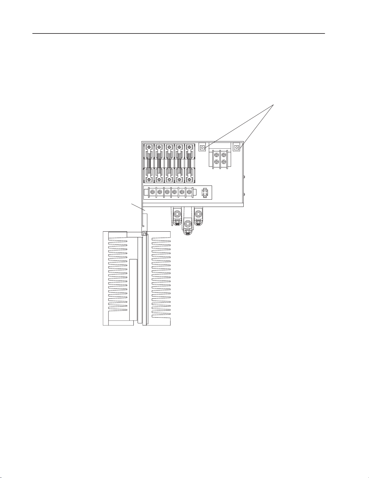
Figure 2.19
DC Motor Field and Armature Connection Locations
100-150 HP at 230 VAC,
200-300 HP at 460 VAC
A1
45
DC MOTOR
ARMATURE
CONNECTION
DANGER
CIRCUIT BREAKER DOES NOT DISCONNECT INCOMING A0
LINE POWER IT ONLY PROVIDES DC FAULT PROTECTION.
LE DISCONECTEUR NE COUPTE PAS L'AUTOMENTATION DU SPOTEUR IL NES
810903-2424
SERT QUE A ASSURER UNE PROTECTION CONTRE LES DESFAULTS DC.
14-10GA 35 LB.-IN
0 GA 48 LB.-IN.
!
DANGER
RISK OF ELECTRICAL SHOCK. DISCONNECT INPUT
POWER BEFORE SERVICING EQUIPMENT.
P/N 33145
GND
TORQUE
.
SPEC
FRONT
SIDE
1 2 3 4 F1 F2
DB
Connections
For
Option
Kits
DC
Motor
Field
Connections
TOP
Publication 1397-5.0 — June, 2001
Page 48

Figure 2.20
DC Motor Field and Armature Connection Locations
400-600 HP at 460 VAC
2–29Installation
Publication 1397-5.0 — June, 2001
Page 49

2–30 Installation
Control Connections
The Bulletin 1397 is supplied with the following standard I/O
compliment:
• 10 Digital Inputs
24V DC internally or externally supplied
8V DC turn–on voltage
0.5 mA turn–off current
• 3 Contact Outputs
250V AC maximum
30V DC maximum
2A maximum resistive load
1A maximum inductive load
• 2 Speed Reference Inputs
Analog Reference 1
±10V DC
4 – 20 mA
10 – 50 mA
Converted within Drive to 12 bit plus sign
Analog Reference 2
External potentiometer (5kΩ min.)
±10V DC
Converted within Drive to 12 bit plus sign
• DC Tachometer Input
10 – 250V DC
Converted within Drive to 12 bit plus sign
• 2 Analog Outputs
±10V DC
4A maximum load
In order to maintain simplicity, the functions of the analog and
digital inputs are fixed. The analog and digital outputs, however,
may be reconfigured. See Chapter 5 for information on parameters
that must be manipulated to reconfigure the outputs.
ATTENTION: The 1397 Drive control circuitry
!
includes solid–state components. If hazards due to
accidental contact with moving machinery or
unintentional flow of liquid, gas or solids exist, an
additional hardwired stop circuit may be required to
remove AC line power to the Drive. When AC input
power is removed, there will be a loss of inherent
regenerative braking effect and the motor will coast to a
stop. An auxiliary braking method may be required.
Publication 1397-5.0 — June, 2001
Page 50

2–31Installation
Control Wiring Procedure
Most control connections on the 1397 Drive are made at the
Regulator Board Terminal Strip which is located at the bottom of the
Drive as shown in Figure 2.21.
Figure 2.21
Regulator Board Terminal Strip Location
J28
Terminal Strip
Regulator Board Input Signal Definitions
The 1397 Drive will recognize a change in the state of a digital input
(e.g. 0-24VDC) if it is applied longer than 20 ms. Power (24VDC)
signals are available on regulator terminal block pins TB-01, TB-07,
TB-11 and TB-14. The associated common connection is present on
TB-15. The Digital inputs shown Figure 2.18 are defined as follows:
TB–01 POWER – A 24VDC supply is available at this pin.
TB–02 RUN – Edge sensitive signal that initiates a Run
command (0 ✒ 1 = Run). If the Drive is Run, voltage
may be applied to the armature causing the motor to
reach the desired speed. The Run input is latched and
therefore does not have to be maintained to keep the
drive Running. This input can be masked through the
[Run Mask] (P. 201) or [Logic Mask] (P.207)
parameters.
Publication 1397-5.0 — June, 2001
Page 51

2–32 Installation
(Refer to Pub. 1397-5.0 for Additional Information)
2> All customer interlock contacts
must be closed for drive operation.
RUN/STOP
by user
contact
Analog Reference 2
*
TB–03 STOP – This is a level sensitive signal that initiates a
Stop command (0 = Stop, 1 = Not Stop). The stopping
mode is determined by the [Stop Mode Type] (P. 115)
parameter. This input CANNOT be masked. Both
customer interlock And
Coast to Stop must be made for
the Drive to be READY.
Figure 2.22
Terminal Strip Inputs
+24V
1
Run
*
*
*
1
2
3
*
*
2
*
*
*
*
PLC End
Analog Reference 1
Analog Reference 2
*
Analog Tachometer In
FWD
REV
ANLG REF 1
ANLG REF 2
3
Regulator Board Terminal Strip Inputs
2
Stop
3
Jog
4
Reverse/Forward
5
Reference Select
6
+24V
7
Coast-to-Stop
8
Customer Interlock
9
Fault Alarm Reset
10
+24V
11
Brush Wear
12
13
Motor Thermostat
14
+24V
15
+24V Common
24V Common
16
+10V (Isolated)
17
+
18
–
+
19
–
20
21
High Range
Low Range
22
23
Common
the
3> The circuit breaker is supplied with
200-300 HP regenerative drives.
Note that if any other interlocks are
required for your application, they
must be connected in series with
the circuit breaker contact to the
customer interlock input.
= Required for initial startup and
*
operational checks.
Voltage must be present at these
points during operation.
Publication 1397-5.0 — June, 2001
24
25
26
27
28
29
30
31
32
Analog Out 1
Analog Out Common
Analog Out 2
Run
Alarm
Fault
Regulator Board Terminal Strip Software Configurable Output Connections
(Drive Contacts Shown In Unpowered State)
Page 52

2–33Installation
TB–04 JOG – This is a edge sensitive signal that initiates a
Jog command (0 ✒ 1 = Jog, 0 = Not Jog). If the Drive
is READY and not already RUNNING, voltage will be
applied causing the motor to reach the value of Jog
Reference. The Drive will Jog for only as long as this
input is asserted. This input can be masked through the
[Jog Mask] (P. 203) or [Logic Mask] (P. 207) parameter.
When released, the Drive will ramp to zero speed based
on the [Jog/Acc/Dec Time] (P. 092). The contactor will
open based on [Jog Off Dly Time] (P. 094).
TB–05 REVERSE/FORWARD – This is a Level sensitive
signal that selects the commanded direction, Forward =
0 or Reverse = 1. This input can be masked through the
[Direction Mask] (P. 202) or [Logic Mask] (P 207)
parameter. If it is not masked, it will assume
control of the drive reference.
TB–06 REFERENCE SELECT – This is a edge sensitive signal
that selects between REF 1 Source (= 1) and
REF2 Source (= 0) parameters to be used as a
reference to the Drive. The input can be masked through
the [Reference Mask] (P 204) or [Logic Mask] (P 207)
parameters. If it is not masked, it will assume control of
the Drive reference. If an I/O Expansion board is
installed, the Preset Speed selection bits will override the
reference selected by this input.
TB–07 POWER – A 24VDC supply is available at this pin.
TB–08 COAST-TO-STOP – Level sensitive input that causes
a Coast Stop command (Open = Stop, Closed = NOT
Stop). The contactor is forced to open by hardware
intervention (i.e. hardware only
), making the motor
coast to rest (if Running). This input is not maskable
and is always active. When the Coast-to-Stop input
is open, the Drive will be Not Ready. If an optional
Dynamic Braking (DB) kit is present, the braking
resistor is automatically applied when the contactor
breaks the armature circuit.
TB–09 CUSTOMER INTERLOCK – Level sensitive input that
causes a Coast Stop command (0 = Stop, 1 = NOT Stop).
The contactor is forced to open through firmware,
making the motor coast to rest (if Running). The input
allows external user interlock signals to be part of the
Drive ready logic. This input CANNOT be masked.
TB–10 FAULT/ALARM Clear – Edge sensitive input that
clears fault and/or alarm indicator(s) (0 ✒ 1 = Clear).
The fault and alarm log entries are not affected. This
input can be masked through the [Fault Reset Mask]
(P 205) or [Logic Mask] (P 207) parameters.
Publication 1397-5.0 — June, 2001
Page 53

2–34 Installation
TB–11 POWER – A 24VDC supply is available at this pin.
TB–12 MOTOR BRUSH WEAR – Level sensitive input that
causes a motor brush wear alarm (0 = ALARM). The
Drive can still operate under this condition. This input
CANNOT be masked.
TB–13 MOTOR THERMOSTAT – Level sensitive input that
causes a motor thermostat fault (0 = FAULT). The
Drive will be faulted while this input is true. This input
CANNOT be masked.
TB–14 POWER – A 24VDC supply is available at this pin.
TB–15 COMMON – A 24VDC common supply is available at
this pin.
TB–16,17,18 ANALOG REFERENCE 2 – Fixed ± 10VDC analog
reference.
TB–19,20 ANALOG REFERENCE 1 – Signal type selected by
Anlg In 1 Type (P.128) parameter (0–10 VDC, ±10
VDC, 4-20mA, 10–50mA) and hardware jumpers on
the regulator board (J10 and J12).
TB–21,22,23 ANALOG TACHOMETER IN – Use of #21 or #22 is
determined by J14 hardware jumper on the regulator.
ATTENTION: If motor rotation is changed by
!
1. Wiring the Coast Stop Circuit
The 1397 Drive has the capability to accept an input from either a
24VDC or 115VAC contact (If the 115 VAC Control Option Board is
installed). The contact must be normally closed and will typically be
a Stop pushbutton. Refer to the following paragraphs for connection
information. This input cannot be masked and is always active.
!
reversing either the motor armature lead connections or
the field connections, the Pulse Encoder feedback
polarity on the B and NOT B leads must be reversed. If
a DC Tach is used, feedback polarity must also be
reversed. Failure to observe this precaution could result
in personal injury or damage to equipment.
ATTENTION: The Run/Stop and customer interlock
circuitry in this Drive is composed of solid-state
components. A hardwired Coast to Stop circuit must be
used with this Drive. For 115VAC control, this
circuitry may be added on the optional 115VAC Control
Board.
Publication 1397-5.0 — June, 2001
Page 54

2–35Installation
ATTENTION: If Dynamic Braking is used as an
!
24V DC INPUT – If 24VDC COAST TO STOP is desired, the
contacts of the ECOAST device must be wired to terminals 7 and 8
of the regulator board terminal strip as shown in Figure 2.23.
alternative stopping method, DO NOT use a hardwired
Stop device that removes AC line power. This will
de-energize the shunt field, causing a loss of the DB
effect and the motor will coast to a stop. Hazards to
personnel may exist if the machine is allowed to coast
to a stop.
Figure 2.23
Regulator Board Terminal Strip 24VDC Inputs
COAST
STOP
24V
1 2 3 4 5 6 7 8 9 10 11 12 13 14 15 16 17 18 19 20 21 22 23
ATTENTION: Applying improper input voltage could
!
115V AC INPUT – If you are using 115VAC inputs for control, a
115 VAC Control Option Board must be installed and wired to your
regulator board. If the 115VAC Control Board is not installed on
your 1397, follow the instructions provided with the 115V Control
Board option kit to install the board before proceeding with control
wiring.
!
damage the regulator board. Make certain that only
24VDC is being applied to the Regulator board terminal
strip. If 115VAC inputs are desired, an optional
115VAC Control Option Board is required!
ATTENTION: The Drive and 115 VAC Control
Option Board are at Line Voltages when connected to
sources of incoming AC power. Disconnect, Tag and
Lockout all sources of AC power to the Drive and the
115VAC Option Board before performing the following
procedure. Failure to observe these precautions could
result in personal injury or loss of life.
115V AC COAST TO STOP inputs are installed at terminals 7 and 8
of the CON2 connector on the 115VAC option board as shown in
Figure 2.24.
Publication 1397-5.0 — June, 2001
Page 55

2–36 Installation
Figure 2.24
CON 2 Terminal Strip 115 VAC Inputs
115V HI L1
COAST STOP (IN6)
CUSTOMER
115V HI (L1)
RUN (IN1)
STOP (IN2)
JOG (IN3)
REV/FWD (IN4)
REF SELECT (IN5)
1 2 3 4 5 6 7 8 9 10 11 12 13 14
2. Wiring Customer Interlocks
Wire the Customer Interlock as shown in Figure 2.25. Both the 24V
Regulator Board Terminal Strip and the 115VAC CON2 Terminal
Strip utilize terminal #9 and #11 as the connection point for a
Customer Interlock. All customer interlocks must be closed for
Drive operation and CANNOT be masked.
INTERLOCK (IN7)
FAULT RESET (IN8)
115V HI (IN8)
BRUSH WEAR (IN9)
MOTOR
THERMOSTAT (IN 10)
115V HI (L1)
Figure 2.25
Wiring Customer Interlocks
9
11
Regulator Board Terminal Strip
24VDC Customer Interlock Circuit
3. Wiring the Motor Thermostat/Brush Wear Circuits
Either a 24VDC or 115VAC input can be used to receive an external
voltage for a normally closed contact used in a motor thermostat
circuit. As shown in Figure 2.26, Terminal 13 is used for the motor
thermostat circuit on both 24VDC and 115VAC configurations. If
the motor thermostat circuit is open, the Drive will display a fault
and coast to a stop.
Terminal 12 is used for a level sensitive input that triggers a motor
brush wear alarm. The Drive will continue to operate under this
condition. Both the MOTOR BRUSH WEAR and MOTOR
THERMOSTAT inputs are always active and CANNOT be masked.
9
11
Customer
Interlock (IN7)
115VAC Customer
Interlock Circuit
115VAC Option Board CON 2
115VAC Customer Interlock Circuit
Publication 1397-5.0 — June, 2001
Page 56

Figure 2.26
Motor Thermostat/Brush Wear Wiring
2–37Installation
12
13
14
BRUSH WEAR
MOTOR THERMOSTAT
+24V
Regulator Board Terminal Strip
24VDC Thermostat/Brush Wear Circuit
The contacts of the motor thermostat and Brush Wear must be N.C.
The Drive interprets a voltage at Terminals 12 & 13 as a normal
expected condition. This input CANNOT be masked.
4. Wiring the Fault/Alarm Reset Circuit
This input clears fault and/or alarm indicators and resets the circuit.
As shown in Figure 2.27 the Fault/Alarm Reset circuit requires a
N.O. operator device that closes to cause a reset. This input can be
masked using the [Fault Reset Mask] (P. 205) or [Logic Mask]
(P. 207).
Figure 2.27
Fault/Alarm Wiring
12
13
14
BRUSH WEAR
MOTOR THERMOSTAT
115V HI
115VAC Option Board CON 2
115VAC Thermostat/Brush Wear Circuit
10
11
Fault/Alarm Reset
+24VDC
Regulator Board Terminal Strip
24VDC Fault/Alarm Reset Circuit
10
11
Fault/Alarm Reset
+115VAC
115VAC Option Board CON 2
115VAC Fault/Alarm Reset Circuit
Publication 1397-5.0 — June, 2001
Page 57

2–38 Installation
5. Wiring the Control I/O Circuits
Both the 24VDC and 115VAC control circuits use the # 1 thru #6
terminals on their respective terminal strips for control functions as
shown in Figure 2.28.
Figure 2.28
Control I/O Wiring
1
2
3
4
REV
FWD
ANLG REF1
ANLG REF2
5
6
Regulator Board Terminal Strip
24VDC Control I/O Connections
+24V
RUN
STOP
JOG
REV/FWD
REF SELECT
REV
FWD
ANLG REF1
ANLG REF2
1
2
3
4
5
6
115VAC Option Board CON 2
115VAC Control I/O Connections
The RUN connection is made at terminal 2 on both 24VDC and
115VAC terminal strips. The Run input is latched and therefore does
not have to be maintained to keep the Drive Running. This input can
be masked through the [Run Mask] (P. 201) or [Logic Mask]
(P. 207) parameter.
The STOP connection is made at terminal 3 on both 24VDC and
115VAC terminal strips. The stopping mode is determined by the
[Stop Mode Type] (P. 115). This input CANNOT BE MASKED.
+115V (L1)
RUN (IN1)
STOP (IN2)
JOG (IN3)
REV/FWD (IN4)
REFERENCE
SELECT (IN5)
Publication 1397-5.0 — June, 2001
ATTENTION: If Dynamic Braking is used as an
!
alternative stopping method, DO NOT use a hardwired
Stop device that removes AC line power. This will
de-energize the shunt field, causing a loss of the DB
effect and the motor will coast to a stop. Hazards to
personnel may exist if the machine is allowed to coast
to a stop.
ATTENTION: You have the ultimate responsibility to
!
determine which stopping method is best suited to the
application and will meet applicable standards for
operator safety.
Page 58

2–39Installation
The JOG connection is made at terminal 4 on both 24VDC and
115VAC terminal strips. The Drive will jog when this input is
asserted, if the Drive is Ready and not already Running. This input
can be masked through the [Jog Mask] (P. 203) or [Logic Mask]
(P. 207).
The DIRECTION connection is made at terminal 5 on both 24VDC
and 115VAC terminal strips. This level sensitive input selects
between Forward (= 0) and Reverse (= 1). This parameter can be
masked through the [Direction Mask] (P. 202) or [Logic Mask]
(P. 207) parameters.
The REFERENCE SELECT connection is made at terminal 6 on
both 24VDC and 115VAC terminal strips. This level sensitive input
selects between ANALOG REFERENCE 1 (= 1) and ANALOG
REFERENCE 2 (= 0) parameters to be used as the reference to the
Drive. This parameter can be masked through the [Reference
Mask] (P.204) or [Logic Mask] (P. 207) parameters. NOTE: If an
I/O expansion board is installed, the Preset Speed selection bits will
override the reference selected by this input.
6. Wiring the Analog Input Circuits
Terminals TB16 thru TB23, as shown in Figure 2.29 are used for
reference and feedback signals.
ANALOG REFERENCE 2 is a fixed ± 10 VDC reference which is
connected at terminals 16, 17 and 18.
ANALOG REFERENCE 1 which is connected at Terminals TB19
and TB20 is a selectable signal type reference determined by [Anlg
In 1 Type] (P. 128) and regulator board jumpers J10 and J12.
ANALOG REFERENCE 1 can be set for 0-10 VDC, ±10 VDC,
4-20mA or 10-50 mA.
Figure 2.29
Regulator Board Terminal Strip
Analog Input Connections
PLC END
Analog Ref 2
Analog Ref 1
PLC END
16
17
18
19
20
+10V (ISOL)
+
–
+
–
Publication 1397-5.0 — June, 2001
Page 59

2–40 Installation
7. Wiring the Output Circuits
The 1397 Drive contains 2 Analog Outputs and 3 Digital Outputs as
illustrated in Figure 2.30.
The Analog Outputs are fixed +/– 10 VDC outputs that are updated
every 20 ms by the Drive and are sent thru a 100 ms running
averaging filter within the drive.
ANALOG OUTPUT 1 is connected at terminals 24 and 25 and
[Anlg Out 1 Src] (P 145) determines which Drive testpoint is the
source selected.
ANALOG OUTPUT 2 is connected at terminals 25 and 26 and
[Analog Out 2 Src] (P. 148) determines which Drive testpoint is the
source selected.
The Digital Outputs indicate the present operating state of the
Drive and are connected as follows:
Terminals 27–28 – 1 = Running 0 = Not Running
Terminals 29–30 – 1 = Alarm active 0 = No alarms active
Terminals 31–32 – 0 = Fault active 1 = No faults active
Figure 2.30
Regulator Board Terminal Strip
Output Connections
24
25
26
27
28
29
30
31
32
ANALOG OUT 1
ANALOG OUT Common
ANALOG OUT 2
RUNNING
ALARM
FAULT
Publication 1397-5.0 — June, 2001
Page 60

Programming Terminal
Chapter 3
General
HIM Description
Chapter 3 describes the various controls and indicators found on the
optional Human Interface Module (HIM). The material presented in
this chapter must be understood to perform the start-up procedure in
Chapter 4.
When the Drive mounted HIM is supplied, it will be accessible from
the front of the Drive as shown in Figure 3.1. The HIM has two main
functions:
• To provide a means of programming the Drive and viewing
operating parameters.
• To allow different Drive functions to be controlled.
The HIM is divided into two sections; Display & Programming
Panel and Control Panel. The Display Panel provides a means of
programming the Drive and viewing the various operating
parameters. The Control Panel allows you to control different drive
functions.
IMPORTANT: The operation of some HIM functions will depend
upon parameter settings.
Figure 3.1
Human Interface Module Sections
Display Panel
Control Panel
Publication 1397-5.0 — June, 2001
Page 61

3–2 Programming Terminal
Figure 3.2
HIM Front Panel
Key Descriptions
Descriptions of the keys used with the 1397 Drive are presented in the
following paragraphs.
Escape
When pressed, the ESCape key will cause the programming
system to go back one level in the menu tree.
Select
Pressing the SELect key alternately causes the top or bottom
line of the display to become active. The flashing first character
indicates which line is active.
Increment/Decrement
These keys are used to increment and decrement a
value or scroll through different groups or parameters.
Enter
When pressed, a group or parameter will be selected or a
parameter value will be entered into memory. After a parameter
has been entered into memory, the top line of the display will
automatically become active, allowing another parameter (or
group) to be chosen.
Publication 1397-5.0 — June, 2001
Page 62

3–3Programming Terminal
Run
By default, this key will initiate Drive operation if hardware is
enabled, (ie. Drive is ready and no other control devices are
sending a Stop command. To change this function, the [Start
Mask] (P. 201) or [Logic Mask] (P 207) parameter must be
reconfigured. Refer to Chapter 5. If the Drive is jogging or
already running, the key has no effect.
Stop
When pressed, a stop sequence will be initiated, causing a
controlled stop to occur, as determined by [Stop Mode Type]
(P. 115). The HIM also sends a “Fault Clear” which can be
masked.
Jog
By default, when this key is pressed the motor will jog at a
speed determined by the [Jog Reference] (P. 093) parameter.
Releasing the key will cause the motor to ramp to zero and the
contactor will open based on Jog Off Dly Time (P. 094).
Change Direction (Key Active Only on Regen Drives with
[Reverse Disable] set to off and [Encoder Quad] to ON.
Pressing this key will cause the motor to change direction. The
appropriate Direction Indicator will light to indicate direction.
Direction LEDs (Indicators)
These LEDs will illuminate to indicate the direction of motor
rotation. [Direction Mask] (P. 202) and [Logic Mask] (P. 207)
must be set to allow HIM control of direction change.
If both of these LED’s are lit, the one that is steadily lit
indicates the commanded direction, while the flashing LED
indicates the actual direction.
NOTE: All Run, Jog and Direction keys can also be affected
by the [Logic Mask] (P. 207). It may be necessary to set or
disable parameter 207 when configuring keys.
Publication 1397-5.0 — June, 2001
Page 63

3–4 Programming Terminal
Up/Down Arrows (only available with digital speed control)
Pressing these keys will increase or decrease the HIM
reference command. An indication of this command will
be shown on the visual Speed Indicator. The Drive will
use this reference if the HIM is the selected reference
source.
Pressing both keys simultaneously stores the current
HIM reference command in HIM memory. Cycling
power or removing the HIM from the Drive will set the
reference command to the value stored in HIM memory.
If the Analog Speed Potentiometer option has been
ordered, the Up/Down keys and Speed Indicator will be
replaced by the pot.
Speed Indicator
Illuminates in steps to give an approximate visual
indication of the commanded speed.
If the Analog Speed Potentiometer option has been
ordered, the Up/Down keys and Speed Indicator will be
replaced by the pot.
Publication 1397-5.0 — June, 2001
Page 64

3–5Programming Terminal
HIM Operation
When power is first applied to the Drive, the HIM will cycle through
a series of displays. These displays will show Drive name, HIM ID
number and communication status. Upon completion, the Status
Display will be shown.
Figure 3.3
Status Display
This display shows the current status of the Drive (i.e. “Ready,”
“Running,” etc.) or any faults that may be present. The Status Display
can be replaced by the Process Display or Password Login menu. See
appropriate sections on the following pages for more information.
From this display, pressing any key will cause “Choose Mode” to be
displayed. Pressing the Increment or Decrement keys will allow
different modes to be selected as described on the pages that follow.
Display
When selected, the Display mode allows any of the parameters to be
viewed. However, parameter modifications are not allowed.
Program
Program mode provides access to the complete listing of parameters
available for programming.
Process
The Process mode displays two user-selected parameters with text
and scaling programmed by the user.
Search (Available on Series B HIM only)
This mode will search for parameters that are not at their default values.
Control Status (Available on Series B HIM only)
Permits the drive logic mask to be disabled/enabled allowing HIM
removal while Drive power is applied. This menu also provides access
to a fault queue and a warning queue which will list the last ten faults or
alarms, respectively that have occurred. “Trip” displayed with a fault
indicates the actual fault that tripped the Drive. A clear function clears
the queue – it will also clear an active fault/alarm condition.
Password
The Password mode protects the Drive parameters against
programming changes by unauthorized personnel. When a password
has been assigned, access to the Program/EEProm modes and the
Control Logic/Clear Fault Queue menus can only be gained when the
correct password has been entered. The password can be any five
digit number between 00000 and 65535.
Publication 1397-5.0 — June, 2001
Page 65

3–6 Programming Terminal
FIGURE 3.4
1397 HIM Programming Steps
DISPLAY PROCESS
Process Display
Power-Up Mode &
OPERATOR LEVEL
Status Display
ESC SEL
or or or or
"Choose Mode"
**
PROGRAM EEPROM SEARCH CONTROL
STATUS
Reset Defaults
Upload Parameters
Download Parameters
Recall Values
Save Values
Control Logic
Fault Queue
Warning Queue
GROUP LEVEL
MODE LEVEL
PASSWORD
Login, Logout
Modify
METERING
Publication 1397-5.0 — June, 2001
ADVANCED
SETUP
SETUP
Series B HIM (or later) only
*
REFERENCE
SET
FEATURE
SELECT
INPUT
CONFIG
OUTPUT
CONFIG
DIAGNOSTICS
MASKS
OWNERS
ADAPTOR
I/O
SEE CHAPTER 5 FOR SPECIFIC PARAMETER DESCRIPTIONS
PROCESS
DISPLAY
FIELD
PROCESS
PI
PARAMETER LEVEL
LINEAR
LIST
Page 66

3–7Programming Terminal
Program and Display Modes
or
or
or
1. The Display and Program modes allow
access to the parameters for viewing or
programming.
A. From the Status Display, press Enter (or
any key). “Choose Mode” will be
shown.
B. Press the Increment (or Decrement) key
to show “Program” (or “Display”).
C. Press Enter.
D. Press the Increment (or Decrement) key
until the desired group is displayed.
E. Press Enter.
F. Press the Increment (or Decrement) key
to scroll to the desired parameter.
Choose Mode
Display
Choose Mode
Program
Choose Group
Metering
Anlg In 1
+0 RPM
Bit ENUMs
or
Bit ENUMS (16 character text strings) will
be displayed to aid interpretation of bit
parameters.
G. Select a bit parameter with the Increment
(or Decrement) keys.
H. Press the SELect key to view the ENUM
of the first bit. Pressing this key again
will move the cursor to the left one bit.
A blinking underline cursor will indicate
that you are in the Display mode or that a
Read Only parameter has been accessed.
A flashing character will indicate that the
value can be changed.
Individual bits of a Read/Write parameter
can be changed in the same manner.
Pressing the SELect key will move the
cursor (flashing character) one bit to the
left. That bit can then be be changed by
pressing the Increment/Decrement keys.
Masks
Logic Mask
Terminal Blk
X1111111
Publication 1397-5.0 — June, 2001
Page 67

3–8 Programming Terminal
Process Mode
or
or
or
or
1. When selected, the Process mode will show
a custom display consisting of information
programmed with the Process Display group
of parameters.
A. Follow steps A-C on the preceding page
to access the Program mode.
B. Press the Increment/Decrement key until
“Process Display” is shown. Press Enter.
C. Using the Increment/Decrement keys,
select [Process 1 Par] and enter the
number of the parameter you wish to
monitor. Press Enter.
D. Select [Process 1 Scale] using the
Increment/Decrement keys. Enter the
desired scaling factor. Press Enter.
E. Select [Process 1 Txt 1] using the
Increment/Decrement keys. Enter the
desired text character. Press Enter and
repeat for the remaining characters.
Choose Mode
Program
Choose Group
Process Display
Process 1 Par
5
Process 1 Scale
+
1.00
Process 1 Txt 1
V
and
F. If desired, a second display line can also
be programmed by repeating steps A-E
for [Process 2 xxx] parameters.
G. When process programming is com-
or
plete, press ESCape until “Choose
Mode” is displayed. Press Increment/
Choose Mode
Process
Decrement until “Process” is displayed.
H. Press Enter. This selects which custom
display will be on line 1 and line 2. Use
or
the Increment/Decrement keys to select
Process Var 1=1
Process Var 2=2
process 1 or 2 parameters for line 1.
I. Press SELect to move to line 2. Select
the desired process parameters. A zero
Sets Process Display
as Power-Up Display
can be entered to disable line 2. In
addition, the Process Display can be set
to appear when Drive power is applied
by simultaneously pressing the Increment and Decrement keys while the
Process Display active.
Publication 1397-5.0 — June, 2001
Page 68

3–9Programming Terminal
EEProm Mode
Reset Defaults
or
or
The EEProm mode is used to restore all settings
to factory default values or upload/download
parameters between the HIM and Drive.
1. To restore factory defaults:
A. From the Status Display, press Enter (or
any key). “Choose Mode” will be
displayed.
B. Press the Increment (or Decrement) key
until “EEProm” is displayed. If EEProm
is not in the menu, programming is
password protected. Refer to Password
Mode later in this section.
C. Press Enter.
D. Press the Increment (or Decrement) key
until “Reset Defaults” is displayed.
E. Press Enter to restore all parameters to
their original factory settings.
Choose Mode
Display
Choose Mode
EEProm
EEProm
Reset Defaults
Drive –> HIM
or
F. Press the Stop key to reset the fault, if
one occurs.
2. To upload a parameter profile from the
Drive to the HIM:
A. From the EEProm menu (see steps A-C
above), press the Increment/Decrement
EEProm
Drive –> HIM
keys until “Drive –> HIM” is displayed.
B. Press Enter. A profile name (up to 14
characters) will be displayed on line 2 of
the HIM. This name can be changed or a
Drive –> HIM
1 A
new name entered. Use the SEL key to
move the cursor left. The Increment/
or
Decrement keys will change the
character.
Publication 1397-5.0 — June, 2001
Page 69

3–10 Programming Terminal
Drive –> HIM (continued)
HIM –> Drive
or
C. Press Enter. An informational display
will be shown, indicating the Drive type
and firmware version.
D. Press Enter to start the upload. The
parameter number currently being
uploaded will be displayed on line 1 of
the HIM. Line 2 will indicate total
progress. Press ESC to stop the upload.
E. “Completed” displayed on line 2 will
indicate a successful upload. Press
Enter. If “ERROR” is displayed, see
Chapter 6.
3. To download a parameter profile from the
HIM to a Drive:
Important: The download function will only be
available when there is a valid profile stored
in the HIM.
A. From the EEProm menu (see steps
1A-1C), press the Increment/Decrement
keys until “HIM –> Drive” is displayed.
1397 DC Drive
Version 1.00
Drive –> HIM 60
|||||
Drive –> HIM 210
Completed
EEprom
HIM –> Drive
B. Press the Enter key. A profile name will
be displayed on line 2 of the HIM.
Pressing the Increment/Decrement keys
HIM –> Drive
1 A
will scroll the display to a second profile
or
(if available).
C. Once the desired profile name is dis-
played, press the Enter key. An informational display will be shown, indicating
Master Type
2.01 –> 2.03
the version numbers of the profile and
drive.
D. Press Enter to start the download. The
parameter number currently being
downloaded will be displayed on line 1 of
HIM –> Drive 60
|||||
the HIM. Line 2 will indicate total
progress. Press ESC to stop the download.
E. A successful download will be indicated
by “Completed” displayed on line 2 of the
HIM. Press Enter. If “ERROR” is
Drive –> HIM 210
Completed
displayed, see Chapter 6.
NOTE: After downloading the parameter profile, the data
is NOT automatically saved. Perform a “Save” to save
parameters to non-volatile memory.
Publication 1397-5.0 — June, 2001
Page 70

3–11Programming Terminal
Save Values
or
or
1. To save values in the EEProm Mode:
A. Use the ESCape key if necessary to
reach the “Choose Mode” display.
B. Press the Increment (or Decrement) key
until “EEProm” is displayed.
C. Press Enter.
D. Press the Increment (or Decrement) key
until “Save Values” displayed.
E. Press Enter to save values.
Choose Mode
Display
Choose Mode
EEProm
EEProm
Save Values
Publication 1397-5.0 — June, 2001
Page 71

3–12 Programming Terminal
Search Mode
or
or
Control Status Mode
1. This mode allows you to search through the
parameter list and display all parameters that
are not at the factory default values.
A. From the Status Display, press Enter (or
any key). “Choose Mode” will be
shown.
B. Press the Increment (or Decrement) key
until “Search” is displayed.
C. Press Enter. The HIM will search
through all parameters and display any
parameters that are not at their factory
default values.
D. Press the Increment (or Decrement) key
to scroll through the list.
1. This mode allows the Drive logic mask to be
disabled, thus preventing a Serial Fault
when the HIM is removed with Drive power
applied.
Choose Mode
Display
Choose Mode
Search
A. From the Status Display, press Enter (or
any key). “Choose Mode” will be
Choose Mode
Display
shown.
or
B. Press the Increment (or Decrement) key
until “Control Status” is displayed. Press
Choose Mode
Control Status
Enter.
or
or
C. Select “Control Logic” using the
Increment/Decrement keys. Press Enter.
D. Press the SELect key, then use the
Increment (or Decrement) key to select
Control Status
Control Logic
Control Logic
Disabled
“Disabled” (or “Enable”).
E. Press Enter. The logic mask is now
disabled (or enabled).
Publication 1397-5.0 — June, 2001
Page 72

3–13Programming Terminal
(continued)Control Status Mode
Fault Queue/Clear Faults
or
or
or
or
2. This menu provides a means to view the
fault queue and clear it when desired.
F. From the Control Status menu, press the
Increment (or Decrement) key until
“Fault Queue” is displayed.
G. Press Enter.
H. Press the Increment (or Decrement) key
until “View Faults” is displayed.
I. Press Enter. The fault queue will be
displayed. “Trip” displayed with a fault
will indicate the fault that tripped the
drive.
J. Use the Increment (or Decrement) key
to scroll through the list.
K. To clear the fault queue, press ESCape.
Then use the Increment/Decrement keys
to select “Clear Queue.” Press Enter.
Please note that “Clear Queue” will also
clear active fault conditions.
Control Status
Fault Queue
Fault Queue
View Faults
CAN Comm Lost
F 11 Trip 1
Motor Over Temp
F 07 2
Fault Queue
Clear Queue
Warning Queue/Clear Warning
or
or
3. This menu provides a means to view the
Warning queue and clear it when desired.
L. From the Control Status menu, press the
Increment (or Decrement) key until
“Warning Queue” is displayed.
M. Press Enter.
N. Press the Increment (or Decrement) key
until “View Warnings” is displayed.
O. Press Enter. The Warning queue will be
displayed. “Trip” displayed with a fault
will indicate the fault that tripped the
drive.
P. Use the Increment (or Decrement) key
to scroll through the list.
Q. To clear the Warning queue, press
ESCape. Then use the Inc/Dec keys to
select “Clear Queue.” Press Enter.
Please note that “Clear Queue” will also
clear active warning conditions.
Control Status
Warning Queue
Warning Queue
View Warnings
Brush Wear Low
W 01 1
Sustained Speed
W 32 2
Warning Queue
Clear Queue
Publication 1397-5.0 — June, 2001
Page 73

3–14 Programming Terminal
This Page Intentionally Blank
Publication 1397-5.0 — June, 2001
Page 74

Start–Up and Adjustment
Chapter 4
Introduction
This chapter is a detailed step-by-step procedure for the proper start
up and tuning of the 1397 drive. Among the procedures to be
performed in this chapter are the following:
• Verify Wiring
• Verify proper supply voltages.
• Calibrate drive set-up parameters.
• Set jumper switches
• Execute drive tuning procedures.
The Start Up checklist should be used to record all data.
ATTENTION: Servicing energized industrial control
!
equipment can be hazardous. Severe injury or death
can result from electrical shock, burn, or unintended
actuation of controlled equipment. Hazardous voltages
may exist in the cabinet even with the circuit breaker in
the off position. Recommended practice is to
disconnect and lock out control equipment from power
sources, and discharge stored energy in capacitors, if
present. If it is necessary to work in the vicinity of
energized equipment, the Safety Related Practices of
NFPA 70E, “ELECTRICAL SAFETY FOR
EMPLOYEE WORKPLACES” must be followed.
DO NOT work alone on energized equipment!
ATTENTION: Potentially fatal voltages may result
!
from improper useage of an oscilliscope and other test
equipment. The oscilliscope chassis may be at
potentially fatal voltage if not properly grounded. If an
oscilliscope is used to measure high voltage
waveforms, use only a dual channel oscilliscope in the
differential mode with X-100 probes. It is
recommended that the oscilliscope be used in the A
minus B Quasi-differential mode with the oscilliscope
chassis grounded to an earth ground. Refer to
equipment safety instructions for all test equipment
before using with the 1397.
Publication 1397-5.0 — June, 2001
Page 75

4–2 Start–Up and Adjustment
ATTENTION: Only qualified personnel familiar with
!
the 1397 DC Drive and its associated machinery should
plan and implement the installation, startup and
subsequent maintenance of the Drive. Failure to
comply may result in personal injury and/or equipment
damage.
Required Tools
& Equipment
Recommended Tools
& Equipment
The following equipment is required for start-up and tuning.
• Multimeter capable of 1000V DC/750V AC, with input
resistance of at least 1 megohm.
• Test leads for multimeter
• Assorted screwdrivers (Phillips and blade) and a set of open end
wrenches.
• Clamp on Ammeter (AC and DC with current ratings to match
Drive ratings)
• Programming Terminal (HIM or GPT)
The following equipment is recommended for start-up and tuning.
• Dual trace oscilliscope with A minus B quasi differential
capability
• X100 probes for oscilliscope
ATTENTION: Do Not use a megohmmeter for
!
continuity checks in the Drive. The high voltage of the
megohmmeter can damage the Drive’s electronic
circuits. Failure to observe this precaution could result
in damage to, or destruction of equipment.
General
Publication 1397-5.0 — June, 2001
Only qualified electrical technicians and/or electrical engineers
familiar with solid state controls and circuitry should attempt a 1397
start-up. It is imperative that personnel familiarize themselves with
the functional description portion of this manual.
The Drive employs regulator construction and uses a keypad for
Drive setup, including parameter adjustments and unit selection,
monitoring, and diagnostics. Reference, feedback, and metering
signals can be interfaced to the Drive. The Drive can be controlled
locally by the Human Interface Module (HIM) keypad or remotely
by using the terminals at the regulator board terminal strip.
Page 76

4–3Start–Up and Adjustment
Drive Hardware
Adjustments
Control Transformer Settings
Figure 4.1
Control TransformerTap Settings
100-150 HP @ 230 VAC
200-300 HP @ 460 VAC
183
H4 H2 H3 H1
182
183
H4 H2 H3 H1
TAP SETTINGS FOR
460 VAC INPUT POWER
182
BOTTOM VIEW
183
H4 H2 H3 H1
TAP SETTINGS FOR
230 VAC INPUT POWER
182
Publication 1397-5.0 — June, 2001
Page 77

4–4 Start–Up and Adjustment
Figure 4.2
Control TransformerTap Settings
400-600 HP @ 460 VAC
Primary
Secondary
460V
182
H1 H2 H3 H4
183
SB
400 & 500 HP
X3 X2 X1
F
188A
115V
460V
Primary
182
H1 H2 H3 H4
183
RV
600 HP
189A
X3 X2 X1
Secondary
188A
F
189A
115V
Converting a 300 HP 1397 Drive from 460 to 230 VAC Line Input
Unlike lower horsepower units, 200-300 HP 1397 Drives can be
converted from 460VAC input to 230 VAC input without the use of a
conversion kit. To convert a 300 HP Drive perform the following
steps:
• Disconnect and lock out all incoming power to the Drive.
• Disconnect the jumpers between H2 and H3 on the control
transformer as shown in Figure 4.3.
• Use the jumpers that were removed to connect H1 to H3 and H4
to H2, as shown in Figure 4.3.
• Reconnect power to the Drive.
• Access parameter 51 [Nominal AC Volt], Set the value to 230.
Converting a 600 HP 1397 Drive from 460 to 230 VAC Line Input
Converting a 600 HP Drive from 460 to 230VAC input is NOT
recommended.
A 600 HP 1397 Drive operating off a 230VAC line input may not
have sufficient voltage for the field supply.
Publication 1397-5.0 — June, 2001
Page 78

Figure 4.3
Control Transformer Settings — 230/380/415/460 V AC Drives
for HP Rated Drives
4–5Start–Up and Adjustment
Control Transformer
Set for
AC Input Line
460V
Control Transformer
Set for
AC Input Line
230V
H4
H2
H3
H1
H4
H2
H3
H1
783
783
07-08610273
1966
-030RD
782
782
783
783
782
782
07-08610273
1966
-030RD
for Current Rated Drives
Control Transformer
Set for
415V
AC Input Line
Control Transformer
Set for
380V
AC Input Line
H4
H3
783
783
H2
H1
782
782
H4
783
H3
H2
H1
783
782
782
Publication 1397-5.0 — June, 2001
Page 79

4–6 Start–Up and Adjustment
Motor Ground Check
ATTENTION: A megohmeter can be used for this
!
The DC motor frame and conduit box should be connected to a good
earth ground per the motor instruction.
Verify that there is no path to ground in either the DC motor
armature circuit, the shunt field circuit or the thermostat circuit.
Connect one lead of an ohmmeter to the motor frame and the other
lead to the two armature leads, then to the two field leads and to the
two thermostat leads. If a reading of less than 100,000 ohms is
observed, a ground condition exists and MUST be corrected before
power is applied.
ground check, but all conductors between the motor
and the Drive must be disconnected. The
megohmeter’s high voltage can damage the Drive’s
electronic circuits. Disconnect all conductors between
the motor and Drive before using a megohmeter for
this motor ground check. Failure to observe this
precaution could result in damage to, or destruction of,
the equipment.
Pre–Power Checks
Verify that the Drive has been installed and wired per the installation
instructions listed in Chapter 2, Installation. Of particular
importance are the following:
• Drive Mounting
• Safety Grounds
• General Wiring
• Secure mounting of all connections and components
ATTENTION: Failure to follow wiring guidelines set
!
Record Data
To assist with Start-Up, the information listed in the Pre-Power
Checklist Table must be recorded. This information includes:
• Drive Nameplate Data.
• Motor Nameplate Data.
• Tach/Encoder Data (if applicable).
• Field Supply Type.
• Installed drive options such as AC line disconnects, dynamic
braking, etc.
IMPORTANT: Record all Regulator Board & Option jumper
settings for future reference when replacing parts.
forth in Chapter 2 Installation, may result in machine
malfunction or personal injury.
Publication 1397-5.0 — June, 2001
Page 80

Table 4.A
Pre-Power Checklist
DRIVE NAMEPLATE DATA:
Catalog Number:
M/N:
Ser:
AC Input: Volts Amps
DC Output : Volts Amps
DC Field: Volts Amps
Short Circuit Rating: Amps
HP:
MOTOR NAMEPLATE DATA:
Manufacturer:
Model Number:
Serial Number:
Type:
HP:
RPM:
Arm
Field
Wound Type:
Frame:
Volts
Volts
4–7Start–Up and Adjustment
Amps
Amps
TACHOMETER/ENCODER NAMEPLATE DATA:
Manufacturer:
Model Number:
Serial Number:
Type:
Rated Supply Voltage (encoder only):
Rated Output Voltage
Encoder
Encoder Pulse per Revolution
DC Tach
Volts square wave
(PPR)
Volts at
OPTION NAMEPLATE DATA:
Manufacturer:
Model Number:
Serial Number:
Type:
FIELD SUPPLY DATA:
Volts:
Type:
Volts
RPM
Publication 1397-5.0 — June, 2001
Page 81

4–8 Start–Up and Adjustment
Field Supply Configuration
Verify which shunt field supply has shipped with your Drive.
Configuration procedures will vary depending on field supply type.
ATTENTION: Field Supply configuration must be
!
checked while making the Pre-Power Checks. If your
Drive uses either the optional Enhanced Field Supply
or the Regulated Field Supply, different configuration
procedures are required than with the Standard Field
Supply. Power should not be applied to the motor field
windings prior to adjusting these parameters, as
outlined in the respective field supply’s installation
manual. Failure to properly configure your field
supply could cause the motor to run at excessive speed
or damage the motor which could result in personal
injury or destruction of equipment.
Standard Field Supply (See Note Below)
If the Standard Field Supply (Fig. 4.4) is installed, adjustment is not
necessary.
Figure 4.4
Standard Field Supply Terminations
581
SP2
F1/37
X2
X1
N/P(610273-14R)
H2
H1
SP1
SP3
LINE CT
F1/35
582 583
AC
–
AC
SP4
+
AC
Note: Regulated Field Supply is provided as standard on:
230V Drives with ratings above 45 kW (60 Hp)
460V Drives with ratings above 112 kW (150 Hp)
380/415V Drives with ratings above 35.8 kW (48 Hp)
Publication 1397-5.0 — June, 2001
Page 82

4–9Start–Up and Adjustment
Enhanced Field Supply
The Enhanced Field Supply (Fig. 4.5) allows adjustment of the field
voltage through hardware jumper settings and parameter adjustment.
Prior to applying the Enhanced Field Supply output to the DC
motor’s field windings, the output voltage must be adjusted so that it
doesn’t exceed the rated motor field voltage. This procedure is
described in the Enhanced Field Supply Kit Installation manual,
Publication 1397-5.12.
Figure 4.5
Enhanced Field Supply
P4
P4
P4
582
H1
X1
CT
X2
H2
F2/35
P4
P4
P4
LINE
583
F1/37
581
C
B
A
ATTENTION: It is imperative that the Drive NOT
!
BE STARTED with the field windings in the
un-powered condition. Failure to follow these
procedures may result in a machine malfunction and/or
personal injury.
The output voltage and current of both the enhanced
field supply and the regulated field supply are
determined by the values contained in set-up
parameters.
Publication 1397-5.0 — June, 2001
Page 83

4–10 Start–Up and Adjustment
Regulated Field Supply
The Regulated Field Supply (Fig. 4.6) allows the motor to run above
base speed (i.e. to operate in the constant horsepower range) by
weakening the motor field current. Prior to applying the regulated
field supply output to the DC motor’s field windings, the output
current must be adjusted so that it does not exceed the rated motor
field current. This procedure is described in the Regulated Field
Supply Kit Installation manual, Publication 1397-5.17.
Figure 4.6
Regulated Field Supply Terminations
J3
J3
FLDP3
FLDP3
FLDP3
F1/37
J8
581
37
F1+
J4
J7
R/C
FLDP6
FLDP6
FLDP6
581
583
583
J2
58719-31
J6
J1
582
582
J6
F2/35
J5
35
F2–
Publication 1397-5.0 — June, 2001
Page 84

4–11Start–Up and Adjustment
Pre-Power Verification
ATTENTION: Prior to energizing the Drive, it is
!
Additionally, you must verify that all Drive options are properly
configured for their intended application. These options include, but
are not limited to:
OPTION INSTALLATION MANUAL
• Enhanced Field Supply 1397 – 5.24
• Regulated Field Supply 1397 – 5.17
• 60 HP AC Line Disconnect 1397 – 5.11
• Dynamic Braking 1397 – 5.14
• Pulse Encoder Interface 1397 – 5.13
• Expansion I/O 1397 – 5.19
• AC Tach Interface 1397 – 5.22
• 460/230V Fuse Kit 1397 – 5.16
• Blower Motor Starter 1397 – 5.20
• 150 HP AC Line Disconnect 1397 – 5.21
• 115VAC Control Int Bd 1397 – 5.18
• Inverting Fault C.B. Kit 1397 – 5.29
• AC Line Disconnect Kit 1397 – 5.30
• AC Line Filter Kit 1397 – 5.31
imperative that the installation instructions in Chapter 2
and the Pre-Power checks listed in the previous section
be completely accomplished. No attempt to apply
power should be made if the installation is in question.
Failure to properly install and configure the Drive or
options could result in personal injury and/or
equipment damage.
Ensure that the Coast/Stop input between terminals TB-7 and TB-8
of the Regulator Board is locked in the open state.
If the Drive is equipped with an optional AC disconnect, verify that
the disconnect is in the open position.
Record the motor field polarity in Table 4.B, as terminated at
terminals F1 and F2 of the field terminal strip (Figures 4.7 & 4.8).
Publication 1397-5.0 — June, 2001
Page 85

4–12 Start–Up and Adjustment
DB Connections
2
1
Figure 4.7
DC Motor Field Connection Location
1.5-30 HP at 230 VAC
7-110A @ 380/415 VAC
3-60 HP at 460 VAC
DC Motor
Field
Connection
F2
F1
4
3
TOP
DC Motor
Armature
Connection
45
A1
Publication 1397-5.0 — June, 2001
Page 86

Figure 4.8
DC Motor Field Connection Location
4–13Start–Up and Adjustment
TOP VIEW
45
A1
40 – 75HP at 230 VAC
265A @ 380/415 VAC
75 – 150 HP at 460 VAC
1 2 3 4 F1 F2
DB Connections for
Option Kits
DC Motor Field
Connection
100 – 150 HP at 230 VAC
200 – 300 HP at 460 VAC
A1 A2/S1DBRS2
TOP VIEW
TOP VIEW
400 – 600 HP at 460 VAC
1 2 3 4 F1 F2
DC Motor Field
Connection
Publication 1397-5.0 — June, 2001
Page 87

4–14 Start–Up and Adjustment
Table 4.B
Motor Field Connections
Power-On Checks
Drive Terminal
F1 ( + )
F2 ( – )
Power Application
ATTENTION: The following start-up procedure must
!
be performed with power applied to the Drive. Some
of the voltages present are at incoming line potential.
To avoid electric shock hazard or damage to
equipment, only qualified service personnel should
perform the following procedure. Throughly read and
understand the procedure before beginning. If an event
does not occur while performing this procedure, DO
NOT PROCEED. REMOVE POWER by opening the
branch circuit disconnect device and correct the
malfunction before continuing.
Wire No Motor Terminal
Apply power to the Drive. If you are using a HIM programming
device, the Drive will display the following screen for several
seconds during power-up.
Connecting...
IMPORTANT: If the Drive detects a fault, a statement relating to the
fault will be shown on the display. Record this information, remove
all power and correct the fault source before proceeding.
Drives without AC Line Disconnect
Apply the main power source feeding the Drive, and measure the
voltage present between terminals.
L1 and L2 (181 – 182)
L1 and L3 (181 – 183)
L2 and L3 (182 – 183)
Record the measurements in Table 4.C:
Publication 1397-5.0 — June, 2001
Page 88

Table 4.C
Rated Drive Voltage (No Disconnect Option)
4–15Start–Up and Adjustment
Test Points
L1 to L2
L1 to L3
L2 to L3
Rated AC Voltage (230/380/415 /460V)
Rated AC Voltage (230/380/415/460V)
Rated AC Voltage (230/380/415/460V)
Expected Value Measured Value
Drives with AC Line Disconnect
Apply the main power source feeding the Drive, and energize the
Drive by closing the Drive’s AC line disconnect. Measure the
voltage present between the terminals on the load side of the
disconnect:
81 and 82
81 and 83
82 and 83
Record the measurements in the following table:
Table 4.D
Rated Drive Voltage (With Disconnect Option)
Test Points
81 to 82
81 to 83
82 to 83
Expected Value
Rated AC Voltage (230/380/415/460V)
Rated AC Voltage (230/380/415/ 460V)
Rated AC Voltage (230/380/415/ 460V)
Measured Value
Parameter Set–Up
In all cases, the three-phase input voltage should be equal to the
rated Drive AC input voltage +/–10%. If the voltage is not within
tolerance, verify that the Drive rating is correct or perform the
necessary adjustments to the incoming line voltage so that it
complies with the Drive rating.
All Drives are shipped with factory default parameter settings.
Before making any parameter changes, review Chapter 5,
Programming Parameters. Parameter values are changed using the
Human Interface Module (HIM). Before beginning any changes
become throughly familiar with the HIM.
ATTENTION: Before starting this procedure, make
!
certain that the Coast-to-Stop input is locked in the
open state. The Drive’s AC contactor must remain
open while the parameter set-up is being performed.
Failure to maintain the input and contactor in the open
state could lead to unintended motor or process
equipment operation and subsequent damage.
Publication 1397-5.0 — June, 2001
Page 89

4–16 Start–Up and Adjustment
ATTENTION: Only qualified electrical personnel
!
Table 4.E provides a description of the parameters which must be
properly configured prior to operating the Drive. Unless otherwise
noted, these parameters are located in the Set-Up group. Scroll
through the Set-Up group and set the parameters based on the
application. For additional information, refer to Chapter 5,
Programming Parameters. For information on operation of the
Human Interface Module, see Chapter 3, Programming.
!
familiar with the construction and operation of
electrical equipment and the hazards involved should
install, adjust, operate, and/or service this equipment.
Read and understand this section entirely before
proceeding. Failure to observe this precaution could
result in bodily injury or loss of life.
ATTENTION: The 1397 control circuitry includes
solid-state components. If hazards due to accidental
contact with moving machinery or unintentional flow
of liquid, gas or solids exist, an additional hardwired
stop circuit may be required (in addition to the required
hard wired Coast-to-Stop circuit) to remove AC line
power to the Drive. When AC input power is removed,
there will be a loss of inherent regenerative braking
effect and the motor will coast to a stop. An auxiliary
braking method may be required.
IMPORTANT: Use the EEPROM mode in the programming
terminal to save all parameter changes to EEPROM or they will be
lost when power is removed from the Drive.
ATTENTION: The incorrect setting of Setup
!
parameters can cause an overspeed condition. These
parameters must be set by a qualified person who
understands the significance of setting them. Verify
that the value of these parameters are set accurately for
your application requirements. Failure to observe this
precaution could result in personal injury or equipment
damage.
Publication 1397-5.0 — June, 2001
Page 90

Table 4.E
Parameter Modification Sequence
Parameter Name Par. No. Default Description User Setting
[Stop Mode Type]
[Stop Speed Level]
Feature Select Group
[Max Motor Speed]
Setup Group
[Motor Arm Amps]
Setup Group
P. 11 5
P. 11 6
P.041 500 RPM [Max Motor Speed] is the highest normal running speed of the motor.
P.045 8.0 Amps
Coast P.115 Selects stopping mode of the Drive in response to a normal Stop
command. P.116 sets the threshold speed below which the main
contactor will automatically open after a ramp stop or current limit stop is
asserted. This value should be less than or equal to [Min Process Speed].
[Stop Mode] default is Coast. If you wish to change modes, exit the Set
Up menu and select Stop Mode. Change the default to Ramp or Limit and
then set the [Stop Speed Level] in parameter 116.
This parameter scales the feedback device.
[Max Motor Speed] depends on several factors:
D If there is no field weakening, the top speed is typically the same as the
nameplate base speed.
D If there is field weakening, the top speed is the same as the field weak-
ened speed. Top speed is typically more than the base speed when field
weakening is applied.
ATTENTION: The Drive will not operate properly if
!
this parameter value is wrong. This parameter must be
equal to the rated armature amps on the motor
nameplate. Failure to observe this precaution could
result in damage to or destruction of the equipment.
4–17Start–Up and Adjustment
[Motor Field Amps]
Setup Group
[Motor Arm Volts]
Setup Group
[Feedback Type]
Setup Group
[Anlg Tach
V/1000]
Setup Group
The rated armature current from the motor nameplate.
P.044 0.01
Amps
P.046 240
Volts
P.039 Arm Volt1[Feedback Type] selects the type of feedback signal that is used for the
P.047 18
V/1000
RPM
It only needs to be set if a regulated field supply is installed. Sets the
motor rated hot field amps from the motor nameplate. Scales the field
current feedback.
The rated armature voltage from the motor nameplate.
1
speed/voltage loop. [Encoder] can be selected only if a pulse tachometer
kit is installed.
[Feedback Type] causes the [Neg Current Lim] (step 16) to be set to 0
and [Reverse Disable] (step 4) to be set to On if:
D AC Tach is selected.
D Pulse Tach is selected and [Encoder Quad] is set Off.
This parameter only needs to be set if [Feedback Type] was set to AC
Tach or DC Tach.
1
[Anlg Tach V/1000] is the analog tachometer scaling from the tachometer
nameplate in volts per 1000 RPM. Units are volts DC for DC tachometers
or volts AC RMS for AC tachometers.
This parameter might be limited to less than 200.0 volts/1000 so that
voltage from the tachometer will not be more than 250 V.
ATTENTION: Failure to set the Analog Tach Voltage
!
range correctly can cause an overspeed condition.
Publication 1397-5.0 — June, 2001
Page 91

4–18 Start–Up and Adjustment
Parameter Modification Sequence (cont)
Parameter Name Par No. Default Description User Setting
[Encoder PPR]
Setup Group
[Encoder Quad]
Setup Group
P.048 18 PPR This parameter only needs to be set if [Feedback Type] was set to
Encoder.
[Encoder PPR] sets the pulse tachometer pulses per revolution (PPR)
from the pulse tachometer nameplate.
ATTENTION: The incorrect setting of the Encoder
!
P.049 On This parameter only needs to be set if [Feedback Type] was set to Pulse
Tach.
[Encoder Quad] enables or disables pulse tachometer quadrature.
Set On for a bidirectional pulse tachometer.
Set Off for a unidirectional pulse tachometer.
PPR parameter can cause an overspeed condition.
This parameter must be set by a qualified person who
understands the significance of setting it. Set the
value of this parameter accurately per your application
requirements. Failure to observe this precaution could
result in bodily injury.
[Accel Time]
Setup Group
[Decel Time]
Setup Group
[Max Process Spd]
Setup Group
P.037 5.0
Seconds
P.038 5.0
Seconds
P.042 500 RPM
If [Encoder Quad] is set to Off while Pulse Tach is the selected
[Feedback Type], [Neg Current Lim] will be set to 0 and [Reverse
Disable] set to On (preventing reverse direction).
The time it takes to accelerate from 0 to [Max Motor Speed] (P.041).
Smaller changes in speed take proportionately less time.
If [Trim Mode Type] (P. 117) is set to Proportional, this time value is
modified by [Draw Percent Out] (P.009).
[Decel Time] selects the time it takes to decelerate from [Top Speed] to
0. Smaller changes in speed take proportionately less time.
If [Trim Mode Select] is set to Proportional, this time value is modified by
[Draw Percent Out].
Selects the minimum speed of the Drive without being stopped. It is
typically greater than zero. If it is less than 10% of [Maximum Speed], an
alarm is generated.
ATTENTION: When performing this adjustment, do
!
The maximum speed of the Drive that can be supported by the application
or process. [Max Process Speed] can be less than or equal to [Max
Motor Speed].
If raising this value causes [Min Process Spd] to become less than 10%
of [Max Process Spd], an alarm is generated.
not allow the motor to exceed the maximum safe
speed of the driven equipment as determined by the
equipment manufacturer. Failure to observe this
precaution could result in bodily injury.
Publication 1397-5.0 — June, 2001
Page 92

4–19Start–Up and Adjustment
[Min Process Spd]
Setup Group
[Nominal AC Freq]
Setup Group
[Nominal AC Volts]
Setup Group
[CT Turns Ratio]
Adv Setup
[Jog Acc/Dec Time]
Ref Setup Group
[Jog Reference]
Ref Setup Group
P.043 250 RPM
!
P.050 60 Hz Typically, the value of this parameter is 50 or 60 Hz. Use the up/down
arrow keys to adjust the value to the nominal value of the line frquency in
use. Valid values are 48 to 62 Hz.
P.051 230 VAC1Use the up/down arrow keys to adjust the value to the nominal value of the
AC line RMS voltage in use. Valid values are 200 – 575 VAC.
P.036 NA* The Drive Current Transformer Turns Ratio (TP/Tn). *see page 5–22 for
instructions on determining a CT Turns final default value.
P.092 3.0
Seconds
P.093 250 RPM The operating speed when the Drive is jogging.
[Jog Accel/Decel Time] is the time it takes the jog reference circuit to
reach [Max Motor Speed] from zero.
ATTENTION: This Drive can operate at and
maintain zero speed when this parameter is set to zero.
The user is responsible for assuring safe conditions for
operating personnel by providing suitable guards,
audible or visual alarms, or other devices to indicate
that the Drive is operating at or near zero speed.
Failure to observe this precaution could result in
severe bodily injury or loss of life.
NOTES:
1
Default levels may change based on incoming Voltage levels.
Publication 1397-5.0 — June, 2001
Page 93

4–20 Start–Up and Adjustment
Jumper Settings
The jumper settings for the 1397 Drive determine the regulator type,
program protection, field settings, references for automatic and
manual modes, tachometer voltage range, and armature feedback
scaling.
IMPORTANT: The Diagnostic Parameter group in the 1397 will
display the proper jumper configuration you should use for J11, J14
and J18, based on the parameters you have previously entered.
• Through the HIM, check the proper jumper settings for [J11 Tach
VScale] (P.180), [J14 Tach V Range] (P.181), and [J18 Arm
Fdbk Res] (P.183) in the Diagnostics Menu. Write down the as
displayed settings in the Calculated Setting column of Table 4.G
and in Table 4.F below. Make sure the actual settings match.
Table 4.F
Regulator Board Hardware Jumper Settings
Location of
Hardware Jumper
J11
J14
J18
NOTE: If [Feedback Type] (P.039) is not set to DC Tach or AC Tach, the position of J11 and J14 is ignored.
Recommended Value
Tach V Scale (P 180)
Tach V Range (P. 181)
Arm Fdbk Res (P. 183)
Actual Setting
• Through the HIM, check the current settings for [J15 Reg Type]
(P.182), [J20 Fld Loss] (P. 184), and [J21 Field Supply] (P.185)
in the Diagnostics menu. If these settings are correct for your
system, you do not need to change them. Record the settings in
in Table 4.G.
Note: Only check these parameters after entering the correct values
for the parameters in the setup menu. J11, J14 and J18 are calculated
from the setup menu parameters. When all parameter values and
jumper settings are completed perform an EEPROM save.
Setting the Jumpers
ATTENTION: This equipment is at line voltage when
!
!
AC power is connected to the Drive. Disconnect and
lock out incoming power to the Drive before
proceeding. After power is removed, verify with a
voltmeter at power terminals 181, 182 and 183 that no
voltage exists before touching any internal parts of the
Drive. Failure to observe these precautions could
result in severe bodily injury or loss of life.
ATTENTION: Unless explicitly stated otherwise,
power must be removed before changing any jumper
connection. Failure to observe this precaution could
result in damage to, or destruction of, the equipment.
Publication 1397-5.0 — June, 2001
Page 94

IMPORTANT: Jumpers are read only on powerup, so power must be
cycled for a change to a jumper setting to be recognized by the
Drive.
To set the jumpers:
1. Remove power from the Drive. Remove the cover. Refer to
Chapter 3 for cover removal. You do need to remove the HIM
bracket.
2. The jumpers are located on the regulator board as shown in
Figure 4.9.
3. Change the jumper settings as described in the following
description and record them in the Final Setting column of
Table 4.G.
Table 4.G
Jumper and Adjustment Settings
Jumper/Adjustment Default Setting Calculated Setting Final Setting
J15 (Regulator Type) Speed
J16 (Program Protection) Not Currently Used
J20 (Field Loss Detect) Enable
J21 (Field Supply Jumper) N/A
J19 (Analog Ref 2) Pot
J14 (Tach V Range) 62
J11 (Tach V Scale) 16
J10 (Analog Ref 1) Volts
J12 (Analog Ref 1) Volts
J18 (ARM I FB RB) Position 4
1
Only applicable when the optional Enhanced Field Supply kit is installed.
1
4–21Start–Up and Adjustment
Setting the Regulator Type (Jumper J15)
J15 determines whether the Drive uses speed/voltage or
torque/current regulation mode. This jumper is read only when the
regulator is powered up.
When Current is selected, all speed references become torque
references. For example: Analog Ref 1 and Ref 2 are now Torque
References.
Also note that speed/voltage parameters must be set to provide
overspeed protection for the Drive.
ATTENTION: Failure to correctly set speed/voltage
!
parameters could result in dangerously high motor
speeds. Failure to provide overspeed protection could
result in bodily injury or equipment damage.
Publication 1397-5.0 — June, 2001
Page 95

4–22 Start–Up and Adjustment
Figure 4.9
Regulator Board Jumpers
803624-093A
A
B 1397
J15
J27
J26
J28
J16
J20
R
J15
C
U
R
1
2
J6
ARM 1
J17
FB RB
ARM
1
J18
GROUND
J18
J22
J25
F
IE
D
L
E
D
T
L
E
J20
O
C
T
S
S
E
E
N
G
A
U
B
L
T
L
A
D
Y
E
T
IS
P
O
E
A
R
B
L
S
E
P
E
J16
E
D
P
O
R
IM
O
G
R
R
E
A
N
F
M
IE
T
J21
E
L
N
D
A
J
S
U
B
U
M
L
D
E
P
P
IS
P
E
L
A
R
Y
B
L
B
E
-C
A
-
C
J24
J23
J21
J7
J1
3
4
5
6
7
8
J2
9
10
11
12
13
14
15
16
17
J19
E
X
T
M
A
P
N
O
U
R
T
A
E
F
L
J19
T
A
R
C
A
H
6
T
3
A
1
C
S
/1
1
6
C
H
A
V
L
J11
E
18
J3
19
20
21
22
23
24
N
2
/2
5
2
5
25
V
G
E
0
H
I
2
5
0
m
a
A
L
x
U
O
J14
6
2
J12
m
a
x
V
O
L
M
T
S
A
M
10-50
P
(BO
S
TH)
A
U
P
T
A
O
R
R
K
E
V
F
O
4
L
-
T
2
S
0
J10
26
27
28
J4
29
30
31
32
J12
T
O
R
E
F
J5
J11
J14
J10
Setting Field Loss Detection (Jumper J20)
The Field Loss Detect jumper (J20) determines whether or not a fault
is generated when a field loss occurs.
IMPORTANT: Jumper J20 is ignored if the Field Current Regulator
kit is installed. Therefore, placing J20 in the Disable position will
not disable field loss detection. See the instructions supplied with
the kit for more information on the Field Current Regulator.
NOTE: Jumper J20 has no effect if the drive is equipped with an
enhanced or regulated field supply.
Publication 1397-5.0 — June, 2001
Page 96

4–23Start–Up and Adjustment
ATTENTION: The user must provide external field
!
To detect complete loss of field current, place the jumper on pins 1
and 2 (Enable). When a complete loss is sensed, a fault is generated
and the Drive is coast stopped.
To ignore field loss, place the jumper on pins 2 and 3 (Disable). Any
loss of field current is ignored. Use the Disable option only when no
field exists, such as with a permanent magnet motor or when a
separate field supply is used.
IMPORTANT: Jumper J20 has no effect if a Regulated Field
Supply is installed. No fault is generated with a Regulated Field
Supply.
current loss detection and inhibit Drive operation via
one of the Drive interlocks when Jumper J20 is
positioned to disable. Misapplication of this jumper can
cause the motor to run at dangerously high speeds.
Failure to observe this precaution could result in bodily
injury and/or equipment damage.
Setting the Drive for the Enhanced Field Supply (Jumper J21)
IMPORTANT: This jumper has no effect on the standard field
supply or the optional Field Current Regulator kit.
The Field Supply Jumper (J21) determines the voltage range that the
Drive expects to see from the optional Enhanced Field Supply kit.
Refer to the instructions supplied with the kit for more information
on the Enhanced Field Supply.
The DC voltage range can be either from 45 to 90% or from 90 to
112.5%.
To set the Drive for a voltage range of 45 to 90%, place the jumper
on pins 1 and 2.
To set the Drive for a voltage range of 90 to 112.5%, place the
jumper on pins 2 and 3.
Publication 1397-5.0 — June, 2001
Page 97

4–24 Start–Up and Adjustment
Setting the Source for the Anlg Reference 2 (Jumper J19, Manual Ref
on board)
ATTENTION: The Drive will not operate at the
!
The Manual Ref jumper (J19) determines whether the internal +10 V
isolated power supply or an external +10 V source is used for Analog
Reference 2.
To use the +10V power supply for the Analog Reference 2
potentiometer, place the jumper on pins 2 and 3 (Pot). The supply at
terminal 16 of the regulator board terminal strip is used.
To use an external +10 V source, place the jumper on pins 1 and 2
(Ext). The external reference is connected at terminals 17 and 18 of
the regulator board terminal strip.
NOTE: This input can be used as a trim on the auto mode speed
reference by setting the jumper on pins 1 and 2 (EXT). In this case a
±10 V range can be used.
correct speed if Jumper J19 is not set to the correct
position. Failure to observe this precaution could result
in damage to, or destruction of, the equipment.
Setting the Voltage Range and Scale of an Analog Tachometer
(Jumpers J14 and J11)
The Tach V Range (J14) and Tach V Scale (J11) jumpers set the
voltage range and scale of the analog tachometer.
NOTE: These jumpers are ignored if an analog tach is not used and
if [Feedback Type] (P. 039) is not set to DC Tach or AC Tach.
Note: Jumper J14 determines which terminal is used for tach
connection. Refer to Figure 4.15 for a tach installation illustration.
Table 4.H details tach terminations for Lo or Hi speed operation.
ATTENTION: The Drive can overspeed if jumper J14
!
is set incorrectly, or the tach is wired incorrectly.
Failure to observe this precaution could result in
damage to, or destruction of, the equipment.
Table 4.H
Regulator Board Terminal Strip Tach Terminations
Terminal Terminal
Hi – Range
Lo – Range 22 23 (Common)
During quick start, the Drive calculates the value of the tachometer
voltage range based on the values of [Max Process Speed] (P. 042) and
[Anlg Tach v/1000] (P. 047) and the setting of Feedback Select. The
correct values are displayed under the Diagnostics menu on the HIM.
Verify these jumper settings before performing the auto-tuning
procedure.
21 23 (Common)
Publication 1397-5.0 — June, 2001
Page 98

4–25Start–Up and Adjustment
ATTENTION: The Drive will not operate at the
!
correct speed if jumpers J11 and J14 are not set to the
correct positions. Failure to observe this precaution could
result in damage to, or destruction of, the equipment.
The expected analog tachometer voltage range can be set to a
maximum of 250 or 62V DC. Jumper J11 selects the hardware
circuitry to maximize the resolution over the entire speed range.
Table 4.I
Regulator Board Jumpers
Jumper J14 Jumper J11
Top Speed Tach Volts ≤ 16 Volts
Top Speed Tach Volts ≤ 31 Volts
Top Speed Tach Volts ≤ 62 Volts
Top Speed Tach Volts ≤ 125 Volts
Top Speed Tach Volts ≤ 250 Volts
Note: The output voltage of the tachometer must not exceed 250 V for DC tachometers or 275 RMS for
AC tachometers when the motor is rotating at [Max Motor Speed]. To calculate the output
voltage at top speed, multiply the two parameter values:
Tach Voltage at [Max Motor Speed] = [Max Motor Speed]
1000
Low 16
Low 31/125
Low 62/250
High 31/125
High 62/250
× [Analog Tach v per thousand]
Analog Reference 1 Set–up (Jumpers J12, Autoref and J10, Autoref)
The Anlg In 1 jumpers (J12 and J10 Fig. 4.10) select the type of
analog reference to be used. J12 selects the type of signal (voltage or
milliamps). J10 selects the range.
Figure 4.10
Anlg In 1 Jumper Selection
Scaling the Armature Current Feedback (Jumper 18)
The Arm I FB RB jumper (J18) scales the armature current feedback
signal. The Drive calculates the value of the burden resistor needed
to scale the armature current feedback signal. The calculations are
based on the values of [Motor Arm Amps] (P.045 ) and Maximum
Current (P. 040).
ATTENTION: The Drive will not operate at the
!
correct speed if jumpers J10, J12 and J18 are not set to
the correct positions for your application. Failure to
observe this precaution could result in damage to, or
destruction of, the equipment.
Publication 1397-5.0 — June, 2001
Page 99

4–26 Start–Up and Adjustment
The HIM displays the correct position of the jumper under the
Diagnostics menu [J18 Arm Fdbk Res] (P.183). Verify this jumper
setting before performing the self-tuning procedure.
Verify the Correct Operation
of 24V I/O Inputs
I/O Point
Run
STOP
Jog
Rev/Fwd
Reference Select
Coast to Stop
Customer
Interlock
Fault/Alarm Reset
Brush Wear
Motor Thermostat
Analog Ref 1
Analog Ref 2
Analog Tachometer
Required Contact Sense
No
YES
No
No
No
YES
YES
No
Yes
Yes
No
No
No
Table 4.J lists the standard 1397 I/O input points indicating those
hardware inputs which are required for Drive operation. Some of
these signals may be generated by the terminal strip or a SCANport
device or HIM or both. These signals are identified in the table by
the column labeled “Alternate Control Source”.
NOTE: Required signals MUST be correctly wired to the terminal
strip for proper Drive operation, and cannot be masked. Signals that
are not required may be “masked off” for exclusive control by a
SCANport device or HIM. Masking parameters are described in
detail in Chapter 5: Programming Parameters.
IMPORTANT: Regulator Board terminal Strip Inputs 3, 8, 9, 12 and
13 must be closed for the Drive to be ready.
Table 4.J
Standard I/O Functions
Alternate Control Source
SCANport/HIM
SCANport/HIM
SCANport/HIM
SCANport/HIM
SCANport/HIM
None
None
SCANport/HIM
None
None
Scanport/HIM
Scanport/HIM
None
NO
NC
NO
NO
NO
NC
NC
NO
NC
NC
Analog
Analog
Analog
Start when CLOSED
Stop when OPEN
Jog when closed
Forward = Open Rev = Closed
Selects Analog Ref 2 when Open
Selects Analog Ref 1 when Closed
Opens AC or DB Contactor (if installed)
when OPEN Motor Coasts to Stop
Opens AC contactor when OPEN –
motor coasts to stop
Resets fault / acknowledges alarm
when CLOSED
When OPEN activates warning
Motor will still run.
Opens AC contactor when OPEN –
motor coasts to stop
External speed reference selected
when REF SELECT CLOSED
External speed reference selected
when REF SELECT OPEN
Input for DC (analog) tachometer
Active Function
Publication 1397-5.0 — June, 2001
Page 100

4–27Start–Up and Adjustment
Verify that the standard inputs connected to the Drive are properly
terminated and produce the desired operation. If an input does not
produce the desired result, remove power from the Drive and verify
the installation.
1. Apply power to the Drive.
2. Coast-to-Stop Inpu
position (i.e. not in a coast stop condition) measure the voltage
present between terminals 7 and 8 of the regulator board
terminal strip. The measured voltage should be approximately
0V DC.
Repeat this procedure with the Coast-to-Stop input OPEN (i.e.
Drive in a Coast Stop condition). The measured voltage should
be 24V.
After proper operation is verified leave the Coast-to-Stop input
in its OPEN position (i.e. Coast-to-Stop the Drive).
ATTENTION: Failure to put the Drive in the
!
Coast-to-Stop condition could allow the Drive to
restart when performing the following checks. Failure
to observe this precaution could lead to personal injury
and/or equipment damage.
t – With the Coast Stop input in its CLOSED
3. Stop Input – Repeat step 2, measuring the voltage present
between terminals 1 and 3 of the regulator terminal board. The
voltage across the stop input should be 0VDC with the Stop
input CLOSED (Stop Not initiated), and 24VDC with the stop
input OPEN (stop initiated).
4. Customer Interlock Input
permissive required to operate the Drive. It allows the Drive to
be interlocked with the driven equipment for personnel or
equipment safety purposes. If the Drive is stopped, it is
prevented from running until this input is CLOSED. If the
interlock input OPENS when the Drive is running, the AC
contactor will be forced open, and the motor will coast to a stop.
NOTE: If the application does not require a customer interlock,
verify the terminals 11 and 9 of the regulator board terminal strip
are jumpered, and proceed to Step 5.
Verify that the Customer interlock is operating properly by
repeating Step 2, measuring the voltage present between
terminals 11 and 9 of the regulator board terminal strip. The
voltage across the stop input should be 0V DC with the
Customer Interlock input CLOSED (permissive OK, and 24V
DC with the stop input OPEN (permissive lost).
– The customer interlock input is a
Publication 1397-5.0 — June, 2001
 Loading...