

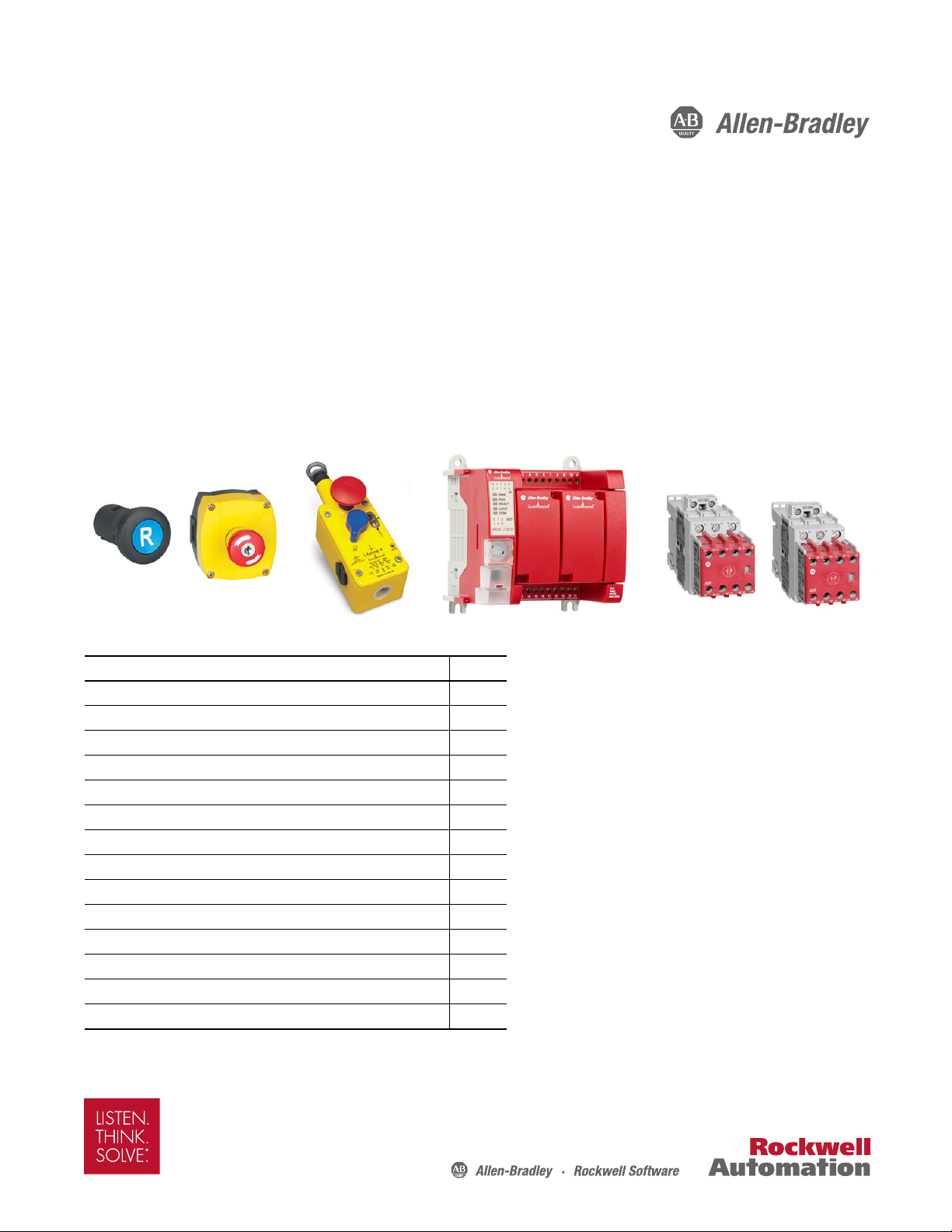
Rockwell Automation Allen-Bradley Lifeline 4, Allen-Bradley Guardmaster 440C-CR30, Allen-Bradley 100S-C Application Technique
Page 1
Application Technique
Safety Function: Cable Pull Switch with a Configurable Safety
Relay
Products: Lifeline 4 Cable Pull Switch, Guardmaster 440C-CR30 Configurable Safety Relay, 100S-C Safety Contactors
Safety Rating: CAT. 3, PLd to ISO 13849-1: 2008
Top ic Pa ge
Important User Information 2
General Safety Information 3
Introduction 3
Safety Function Realization: Risk Assessment 3
Lifeline 4 Cable Pull Switch Safety Function 4
Safety Function Requirements 4
Functional Safety Description 4
Bill of Material 5
Setup and Wiring 5
Configurat ion 6
Calculation of the Performance Level 19
Veri ficat ion an d Valid ation Plan 22
Verification of the Configuration 28
Additional Resources 31
Page 2

Safety Function: Cable Pull Switch with a Configurable Safet y Relay
IMPORTANT
Important User Information
Read this document and the documents listed in the additional resources section about installation, configuration, and
operation of this equipment before you install, configure, operate, or maintain this product. Users are required to
familiarize themselves with installation and wiring instructions in addition to requirements of all applicable codes, laws,
and standards.
Activities including installation, adjustments, putting into service, use, assembly, disassembly, and maintenance are required
to be carried out by suitably trained personnel in accordance with applicable code of practice.
If this equipment is used in a manner not specified by the manufacturer, the protection provided by the equipment may be
impaired.
In no event will Rockwell Automation, Inc. be responsible or liable for indirect or consequential damages resulting from the
use or application of this equipment.
The examples and diagrams in this manual are included solely for illustrative purposes. Because of the many variables and
requirements associated with any particular installation, Rockwell Automation, Inc. cannot assume responsibility or
liability for actual use based on the examples and diagrams.
No patent liability is assumed by Rockwell Automation, Inc. with respect to use of information, circuits, equipment, or
software described in this manual.
Reproduction of the contents of this manual, in whole or in part, without written permission of Rockwell Automation,
Inc., is prohibited.
Throughout this manual, when necessary, we use notes to make you aware of safety considerations.
WARNING: Identifies information about practices or circumstances that can cause an explosion in a hazardous environment,
which may lead to personal injury or death, property damage, or economic loss.
ATTENTION: Identifies information about practices or circumstances that can lead to personal injury or death, property
damage, or economic loss. Attentions help you identify a hazard, avoid a hazard, and recognize the consequence.
Identifies information that is critical for successful application and understanding of the product.
Labels may also be on or inside the equipment to provide specific precautions.
SHOCK HAZARD: Labels may be on or inside the equipment, for example, a drive or motor, to alert people that dangerous
voltage may be present.
BURN HAZARD: Labels may be on or inside the equipment, for example, a drive or motor, to alert people that surfaces may
reach dangerous temperatures.
ARC FLASH HAZARD: Labels may be on or inside the equipment, for example, a motor control center, to alert people to
potential Arc Flash. Arc Flash will cause severe injury or death. Wear proper Personal Protective Equipment (PPE). Follow ALL
Regulatory requirements for safe work practices and for Personal Protective Equipment (PPE).
2 Rockwell Automation Publication SAFETY-AT134B-EN-P - November 2015
Page 3
Safety Function: Cable Pull Switch with a Configurable Safety Relay
IMPORTANT
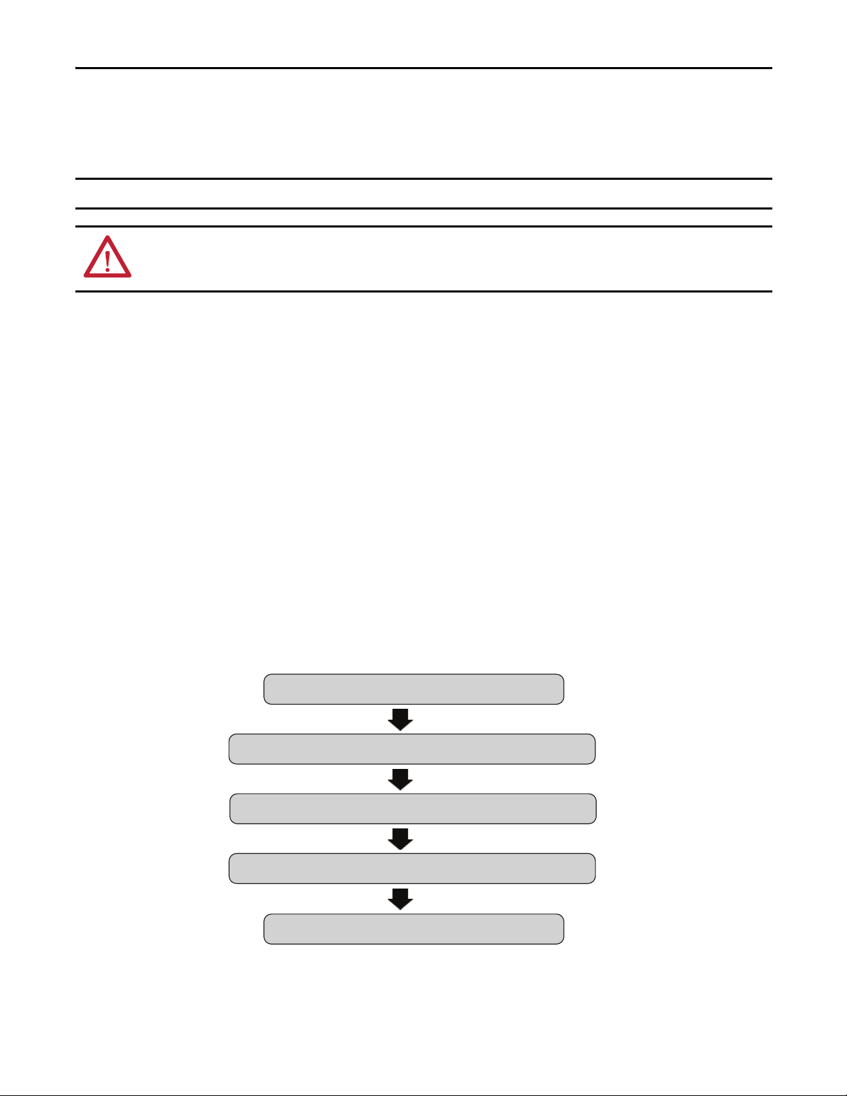
From: Risk Assessment (ISO 12100)
1. Identification of safety functions
2. Specification of characteristics of each function
3. Determination of required PL (PLr) for each safety function
To: Realization and PL Evaluation
General Safety Information
Contact Rockwell Automation to find out more about our safety risk assessment services.
This application example is for advanced users and assumes that you are trained and experienced in safety system requirements.
ATTENTION: Perform a risk assessment to make sure all task and hazard combinations have been identified and addressed. The risk
assessment can require additional circuitry to reduce the risk to a tolerable level. Safety circuits must take into consideration safety
distance calculations, which are not part of the scope of this document.
Introduction
This safety function application technique explains how to wire, configure, and integrate a Lifeline™ 4 cable pull switch,
and an E-stop with a Guardmaster® 440C-CR30 configurable safety relay and two safety contactors. When the Lifeline 4
cable pull switch is tripped, the E-stop is pressed, or a fault is detected, the 440C-CR30 relay turns off two outputs, which
then turn off two safety contactors and remove power from the motor.
Safety Function Realization: Risk Assessment
The required performance level is the result of a risk assessment and refers to the amount of the risk reduction to be carried
out by the safety-related parts of the control system. Part of the risk reduction process is to determine the safety functions of
the machine. In this application, the performance level required (PLr) by the risk assessment is Category 3, Performance
Level d (CAT. 3, PLd), for each safety function. A safety system that achieves CAT. 3, PLd, or higher, can be considered
control reliable. Each safety product has its own rating and can be combined to create a safety function that meets or
exceeds the PLr.
Rockwell Automation Publication SAFETY-AT134B-EN-P - November 2015 3
Page 4

Safety Function: Cable Pull Switch with a Configurable Safet y Relay
Lifeline 4 Cable Pull Switch Safety Function
This application technique includes two safety functions:
• Safety-related stop function initiated by a safeguard (Lifeline 4 cable pull switch)
• Manually-actuated Emergency stop (E-stop)
These safety functions both execute a Stop Category 0 stop.
Safety Function Requirements
Actuating the Lifeline 4 cable pull switch stops and prevents hazardous motion by de-energizing the redundant safety
contactors. When the cable pull switch is de-activated, the 440C-CR30 relay is reset, and no faults are detected, motion
does not resume until a secondary start command is issued by the external start/stop system.
Pressing the E-stop prevents hazardous motion by de-energizing the redundant safety contactors. When the E-stop is deactivated, the 440C-CR30 relay is reset, and no faults are detected, motion does not resume until a secondary start
command is issued by the external start/stop system.
The safety functions in this application technique each meet or exceed the requirements for Category 3, Performance
Level d (CAT. 3, PLd), per ISO 13849-1 and control reliable operation per ANSI B11.19.
Functional Safety Description
An assembly conveyor needs to be protected from accidental contact with personnel. The risk assessment determined that,
due to the length of the hazardous area, a cable pull switch must be installed to protect the area and to help mitigate the
risk. When the switch is activated, a Stop Category 0 stop takes place on the conveyor motor. The cable pull switch
prevents unexpected startup of the machine while the switch is activated.
An E-stop is also provided to address unanticipated emergency situations. The E-stop is a manually-actuated
complementary safety device. Pressing the E-stop also initiates a Stop Category 0 stop of the conveyor motor. The E-stop
switch prevents unexpected startup of the machine while the E-stop is depressed.
After a safety-related stop, the safety system cannot be reset unless the cable pull switch is reset and the E-stop is released.
Once the safety system is reset, a separate, deliberate action can be used to restart the conveyor with the external start/stop
system.
4 Rockwell Automation Publication SAFETY-AT134B-EN-P - November 2015
Page 5

Safety Function: Cable Pull Switch with a Configurable Safety Relay
Bill of Material
This application uses these products.
Cat. No. Description Quantity
440E-L13137 440E emergency stop device – Lifeline 4 cable pull switch 1
100S-C12EJ23BC Bulletin 100S-C safety contactors, 12 A, 24V DC with electronic coil, bifurcated contacts 2
440C-CR30-22BBB Guardmaster 440C-CR30 software-configured safety relay, PLe, SIL 3, 22 safety I/O embedded serial port, USB
programming port, 2 plug-in slots, 24V DC
2080-IQ4OB4 4-channel digital input/output combination module 1
800FP-R611PQ10V 800F reset PB, round plastic (type 4/4x/13,IP66), blue, plastic latch mount, 1 N.O. contact 1
800F-1YP3 800F 1-hole enclosure E-stop station, plastic, PG, twist-to-release 40mm, non-illuminated, 2 N.C. 1
1
Setup and Wiring
For detailed information on installing and wiring, refer to the publications listed in the Additional Resources. Follow the
installation instructions for your cable pull switch to make sure the pull switch operates properly.
System Overview
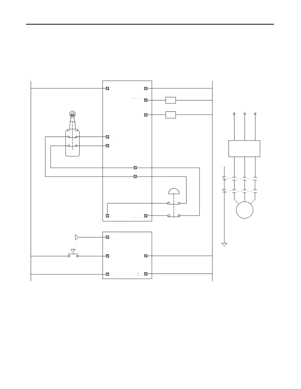
The Lifeline 4 cable pull switch is equipped with two normally closed (N.C.) contacts between two test pulse outputs
(MP_12 and MP_13) of the 440C-CR30 relay and two embedded safety inputs (EI_00 and EI_01). The pulse test
outputs are used to feed the inputs so that shorts can be detected on the input circuits. By using the pulse test outputs to
source the inputs, the 440C-CR30 relay can detect a short between input channels, a short to 24V DC, and a short to
ground. If any of these faults are detected, the 440C-CR30 relay takes the system to a safe state.
The E-stop is equipped with two normally closed (N.C.) contacts between two test pulse outputs (MP_12 and MP_13) of
the 440C-CR30 relay and two embedded safety inputs (EI_02 and EI_03). The pulse test outputs are used to feed the
inputs so that shorts can be detected on the input circuits. By using the pulse test outputs to source the inputs, the
440C-CR30 relay can detect a short between input channels, a short to 24V DC, and a short to ground. If any of these
faults are detected, the 440C-CR30 relay takes the system to a safe state.
If either the Lifeline 4 cable pull switch or the E-stop is depressed, the 440C-CR30 relay reacts by turning off two outputs
(EO_18 and EO_19) which are connected to two safety contactors (K1 and K2). These safety contactors are wired in series
to the motor. When the contactors drop out, motion at the motor stops. Each safety contactor is equipped with a normally
closed (N.C.) contact. The normally closed contact from each safety contactor is wired in series to a plug-in input (P1_00)
on the 440C-CR30 relay to serve as a feedback status for the contactors. This plug-in input is used to reserve the safety
inputs on the 440C-CR30 relay for actual safety devices. A safety input is not required for feedback status. This input is
monitored by the 440C-CR30 relay to make sure that neither safety contactor is welded in the closed position. If the
440C-CR30 relay detects that either contactor is welded closed, it does not let the system restart until the fault has been
corrected and the reset button has been pressed and released.
The reset function is carried out by a push button with a single, normally open (N.O.) contact that is tied to a plug-in input
(P1_01) on the 440C-CR30 relay. This plug-in input is used to reserve the safety inputs on the 440C-CR30 relay for
actual safety devices. A safety input is not required for the reset function. The reset function takes place during the ON-to-
Rockwell Automation Publication SAFETY-AT134B-EN-P - November 2015 5
Page 6
Safety Function: Cable Pull Switch with a Configurable Safet y Relay
24V DC
DC_COM
Cable Pul l Switch
Contac tor–Feed back
Reset–PB
E-stop
24V DC
External_Switched
Start/Stop_Circuit
Feedback–to–P1_00
11 12
21
22
11
12
21
22
A1
EI_00
EI_01
A2
EO_18
EO_19
MP_13
MP_12
K1
K2
L1
L2 L3
K1
K2
M
EI_02
EI_03
440C-CR30-22BBB
2080-IQ40B4
P1_00
P1_01
B4
A3
B4
OFF transition of the reset button. This functionality is built in to the 440C-CR30 relay to make sure that the reset button
has not failed in the ON state, or that no one has defeated the button in the closed position.
Electrical Schematic
Configuration
Configure the 440C-CR30 relay by using Connected Components Workbench™ software, release 6.01 or later. A detailed
description of each step is beyond the scope of this document. Knowledge of Connected Components Workbench
software is assumed.
6 Rockwell Automation Publication SAFETY-AT134B-EN-P - November 2015
Page 7
Safety Function: Cable Pull Switch with a Configurable Safety Relay
Configure the 440C-CR30 Relay
Follow these steps to configure the Guardmaster 440C-CR30 relay by using Connected Components Workbench
software.
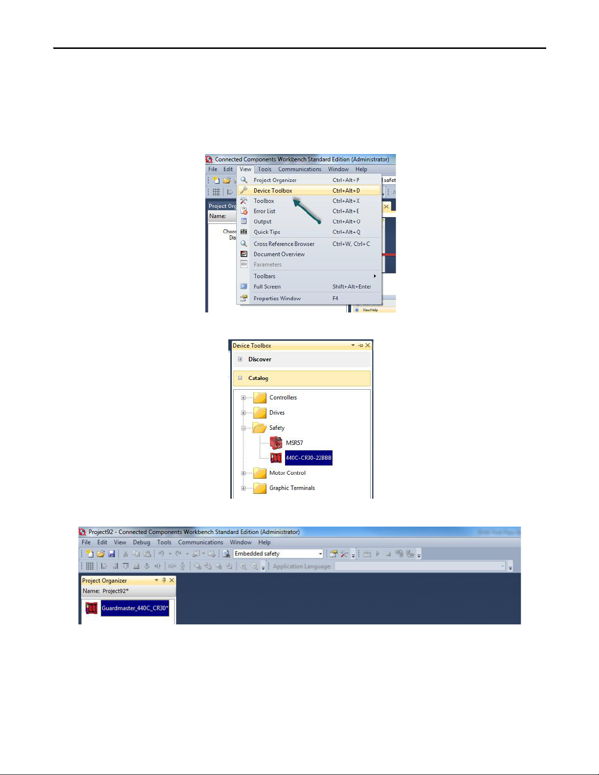
1. In Connected Components Workbench software, choose View and then Device Toolbox.
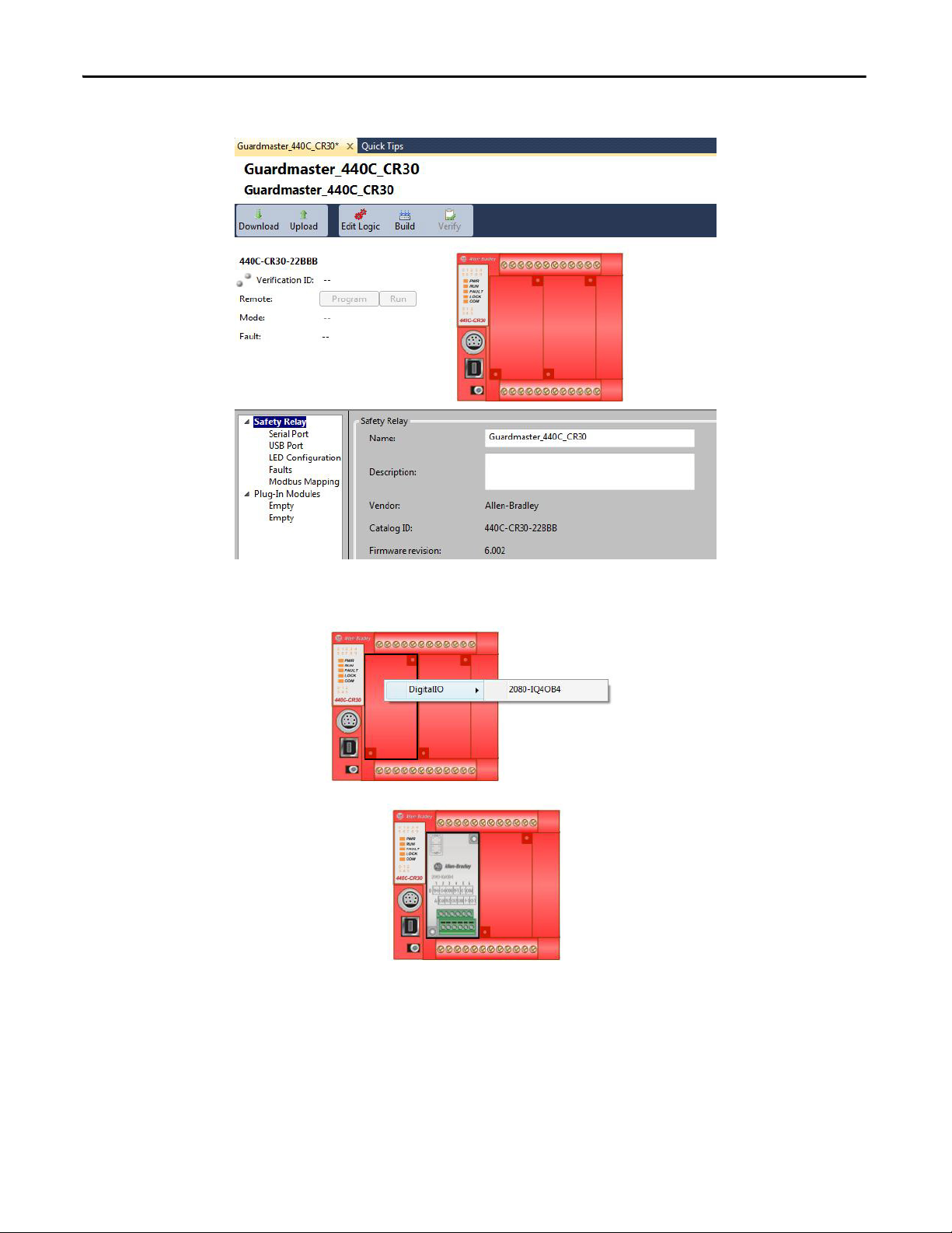
2. Select 440C-CR30-22BBB.
3. In the Project Organizer, double-click the Guardmaster_400C_CR30 relay.
Rockwell Automation Publication SAFETY-AT134B-EN-P - November 2015 7
Page 8
Safety Function: Cable Pull Switch with a Configurable Safet y Relay
TIP
The Guardmaster_440C_CR30 screen appears.
4. To add the plug-in I/O module called for in the schematic, right-click the left plug-in module space and choose the
2080-IQ4OB4 module.
The I/O module is shown in standard gray, because it is not a safety I/O module. That is permissible in this application, because the
standard I/O module is not used to connect safety signals. The contactor feedback and reset button signals are not considered
strict, safety signals. By using standard I/O for these non-safety signals, you can reserve the limited number of safety inputs and
outputs for true safety signals.
8 Rockwell Automation Publication SAFETY-AT134B-EN-P - November 2015
Page 9
Safety Function: Cable Pull Switch with a Configurable Safety Relay
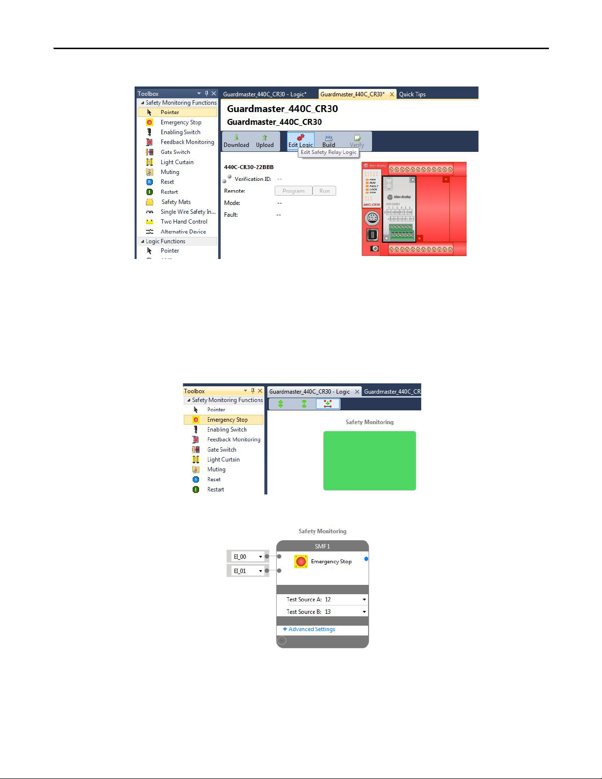
5. Click the Edit Logic button to open the Connected Components Workbench Workspace.
6. From the View pull-down menu, choose Toolbox.
Configure the Inputs
Follow these steps to configure the inputs.
1. Select Emergency Stop.
2. Drag it to the green rectangle under Safety Monitoring and release it.
Rockwell Automation Publication SAFETY-AT134B-EN-P - November 2015 9
Page 10
Safety Function: Cable Pull Switch with a Configurable Safet y Relay
Connected Components Workbench software assigns input terminals EI_00 and EI_01 on the left side of the block.
The software automatically assigns the next unused terminal for a newly-added device. The terminals can be changed
to any unused input terminal, but in this case, leave the default. Because an E-stop is an electro-mechanical device,
the software automatically adds terminals 12 and 13 as test sources. Numbers 12 and 13 refer to multi-purpose
terminals 12 and 13 (MP_12 and MP_13). The diagnostic technique of using the test pulses lets the E-stop be used
in a safety system that achieves the required PL.
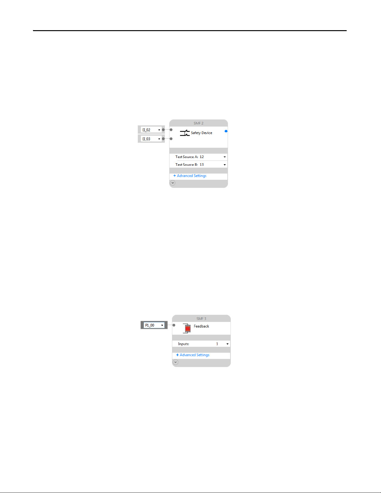
3. To add the Lifeline 4 cable pull switch, which is not included in the Toolbox, select Alternate Device and drag and
release it to the block below the E-stop you added previously.
Connected Components Workbench software assigns input terminals EI_02 and EI_03 on the left side of the block.
The software automatically assigns the next unused terminal for a newly-added device. The terminals can be changed
to any unused input terminal, but in this case, leave the default. Because the Lifeline 4 cable pull switch is an electromechanical device, the software automatically adds terminals 12 and 13 as test sources. Numbers 12 and 13 refer to
multi-purpose terminals 12 and 13 (MP_12 and MP_13). The diagnostic technique of using the test pulses lets the
Lifeline 4 cable pull switch be used in a safety system that achieves the required PL.
4. To add a Feedback Monitoring input from the Toolbox, select Feedback Monitoring and drag and drop it onto the
block below the cable pull switch you added in the previous step.
The input defaults to one of the embedded safety EI inputs, and Connected Components Workbench software
names the block SMF3.
5. Because the feedback block is used to monitor the auxiliary contacts from the two safety contactors, change this to
use the non-safety plug-in module input P1_00, as shown.
6. To add a Reset input from the Toolbox. select Reset and drag and drop it onto the block below the Feedback Device.
The input defaults to one of the embedded safety EI inputs, and Connected Components Workbench software
names the block SMF4.
10 Rockwell Automation Publication SAFETY-AT134B-EN-P - November 2015
Page 11

Safety Function: Cable Pull Switch with a Configurable Safety Relay
7. Because this reset block is used to reset the Immediate OFF Output in the case of a fault, change this to use the nonsafety plug-in module input P1_01, as shown.
These are the completed inputs for the system.
Rockwell Automation Publication SAFETY-AT134B-EN-P - November 2015 11
Page 12

Safety Function: Cable Pull Switch with a Configurable Safet y Relay
IMPORTANT
Configure the Outputs
Follow these steps to configure the safety outputs.
1. From the Toolbox, select and drag the Immediate OFF safety output function block to the top position in the Safety
Output column of the Workspace.
The software displays two automatically-assigned outputs and one blank, unassigned output. One, two, or three
outputs may be configured. For this application we use the defaults shown, which are E0_18 and E0_19. Both of
these outputs default to PT, which is pulse testing. Leave this default setting as well.
2. Using the pull-down menu next to each item in the Immediate OFF safety output function block, change the
following values:
a. Change Feedback to SMF3.
b. Leave Reset Type set to Manual to perform a manual reset on the Immediate OFF safety output function block.
c. Change Reset Input to SMF4.
SMF3 is the name given to the feedback input block created earlier to monitor the auxiliary contacts on the two safety contactors.
SMF4 is the name given to the Reset input function block created earlier to reset this output block.
The completed Immediate OFF output function block appears as shown.
Configure the Logic
The logic ties the inputs to the outputs, making the outputs respond to the inputs in the manner required.
12 Rockwell Automation Publication SAFETY-AT134B-EN-P - November 2015
Page 13

Safety Function: Cable Pull Switch with a Configurable Safety Relay
1. From the Toolbox, select and drag the AND logic function and release it under the Logic Level A header as shown.
2. Connect the logic by completing the following steps:.
a. Click the blue dot on the E-stop input.
It turns gray.
b. Click the upper left blue dot on the AND gate.
The connection is formed.
Rockwell Automation Publication SAFETY-AT134B-EN-P - November 2015 13
Page 14

Safety Function: Cable Pull Switch with a Configurable Safet y Relay
3. Add connections between the Safety Device function block (this is the Lifeline 4 cable pull switch) and the lower
blue dot of the AND gate as shown.
4. Connect the blue dot on the right side of the AND gate to the blue dot of the safety output SOF1.
The software automatically routes the connection through a Pass Through under Logic Level B.
The completed logic looks like this.
14 Rockwell Automation Publication SAFETY-AT134B-EN-P - November 2015
Page 15

Safety Function: Cable Pull Switch with a Configurable Safety Relay
Configure the Status Indicators
The 440C-CR30 relay lets you configure ten input status indicators and six output status indicators. These status
indicators can be very helpful while testing the system during installation and commissioning. They are also useful for
monitoring the system in operation.
To configure LED status indicators to show the status of the E-stop (terminals 00 and 01), follow these steps:
1. Click Guardmaster_440C_CR30.
2. Select LED configuration.
Rockwell Automation Publication SAFETY-AT134B-EN-P - November 2015 15
Page 16

Safety Function: Cable Pull Switch with a Configurable Safet y Relay
E-stop Channel 1
E-stop Channel 2
E-stop Status
Lifeline 4 Channel 1
Lifeline 4 Channel 2
Lifeline 4 Status
Safety Contactor K1 Output
Safety Contactor K2 Output
Immediate Off O utput Status
3. Choose Terminal Status as the Type Filter for LED 0.
4. Choose Terminal 00 as the Value for LED 0.
5. Assign the rest of the Input LED status indicators as follows:
6. Assign the Output LED status indicators as follows:
Confirm the Validity of the Build
Follow these steps to confirm the validity of the logic by using the Build feature in Connected Components Workbench
software.
1. Click Guardmaster_440C_CR30 in the bar above the Workspace.
16 Rockwell Automation Publication SAFETY-AT134B-EN-P - November 2015
Page 17

2. Click Build.
IMPORTANT
A Build Succeeded message confirms that the configuration is valid.
Safety Function: Cable Pull Switch with a Configurable Safety Relay
If an error or omission is discovered during a build, a message is displayed which details the error so that it may be
corrected. After you correct the error, you need to perform the build again.
Save and Download the Project
Follow these steps to save and download the project.
1. From the File menu, choose Save as to save the project.
Saving the project with a new name closes the workspace window(s).
2. In the Project Organizer window, double click Guardmaster_440C_CR30 to open the workspace.
3. Power up the 440C-CR30 safety relay.
4. Connect the USB cable to the 440C-CR30 relay.
Rockwell Automation Publication SAFETY-AT134B-EN-P - November 2015 17
Page 18

Safety Function: Cable Pull Switch with a Configurable Safet y Relay
5. Click Download.
6. In the Connection Browser, expand the AB_VBP-1 Virtual Chassis and select the Guardmaster 440C-CR30-
22BBB.
7. Click OK.
8. Click Yes to change from Run to Program mode.
9. When the download is complete, click Yes to change from Program to Run mode.
18 Rockwell Automation Publication SAFETY-AT134B-EN-P - November 2015
Page 19

Safety Function: Cable Pull Switch with a Configurable Safety Relay
10. Click Edit Logic to see the online diagnostics.
Green indicates that a block is True or that an input or output terminal is ON. Flashing green indicates that a Safety
Output Function is ready to be Reset.
The online diagnostics mode of the 440C-CR30 relay can be very helpful during the verification process.
11. Review the information in C
page 22 before proceeding with Verification of the Configuration on page 28.
alculation of the Performance Level on page 19 and Verification and Validation Plan on
Calculation of the Performance Level
When properly implemented, these safety functions can achieve a safety rating of Category 3, Performance Level d (CAT.
3, PLd), according to ISO 13849-1: 2008, as calculated by using the SISTEMA software PL calculation tool.
The Performance Level required (PLr) from the risk assessment for each of the safety functions in this application is PLd or
better. Additionally, each safety function must achieve a CAT. 3 rating or better.
The Performance Level and Category achieved by each subsystem of the Lifeline 4 cable pull switch safety function, as
calculated by SISTEMA, is shown below.
Rockwell Automation Publication SAFETY-AT134B-EN-P - November 2015 19
Page 20

Safety Function: Cable Pull Switch with a Configurable Safet y Relay
Input
Logic
Output
Cable Pull Switch 1
S1
Cable Pull Switch 2
S2
Subsystem 1
Subsystem 2
Subsystem 3
440C-CR30
Relay
100S-C
K1
100S-C
K2
Subsystem 4
Fault Exc lusi on
Fau lt
Exclusion
The Lifeline 4 cable pull switch safety function can be modeled as follows.
Lifeline4 cable pull switches are considered complimentary safety devices by the relevant standards. As such, they are not a
substitute for safeguarding measures, nor can they impair the effective operations of any safeguarding measures.
Due to the single mechanical actuator of the cable pull switch, a fault exclusion must be considered. In most instances the
fault exclusion required for electromechanical devices with a single mechanical actuator, such as a typical tongue interlock,
limits the safety function in which they are included to a maximum Performance Level of PLd.
Calculation of the 440C-CR30 relay subsystem is straightforward. Its relevant safety data is automatically entered into
SISTEMA when it is selected from the Rockwell Automation SISTEMA library.
The calculation for the Lifeline 4 cable pull switch input subsystem, and the 100S contactor output subsystem is different.
Because these are electro-mechanical devices, the Lifeline 4 cable pull switch and safety contactor data includes the
following:
• Mean Time to Failure, dangerous (MTTFd)
• Diagnostic Coverage (DCavg)
• Common Cause Failure (CCF)
• Electro-mechanical devices' functional safety evaluations include the following:
• How frequently they are operated
• Whether they are effectively monitored for faults
• Whether they are properly specified and installed
• SISTEMA calculates the MTTFd by using B10d data provided for the contactors along with the estimated
frequency of use, entered during the creation of the SISTEMA project. In this application, the estimated annual
number of contactor operations is 17520 per year (the Lifeline 4 cable switch is initiated once per hour, plus the
E-stop is initiated once per hour, 24 hours per day, 365 days a year).
The DCavg (99%) for the contactors is selected from the Output Device table of ISO 13849-1 Annex E, Direct
Monitoring.
The DCavg (99%) for the E-stop is selected from the Input Device table of ISO 13849-1 Annex E, Cross Monitoring.
20 Rockwell Automation Publication SAFETY-AT134B-EN-P - November 2015
Page 21

Safety Function: Cable Pull Switch with a Configurable Safety Relay
Subsystem 1 Subsystem 2 Subsystem 3
Subsystem 4
Input
Logic
Output
Fault Exclusion
E-stop
E-stop
Fau lt
Exclusion
440C-CR30
Relay
100S-C
K1
100S-C
K2
The DCavg (99%) for the Lifeline 4 cable pull switch is selected from the Input Device table of ISO 13849-1 Annex E,
Cross Monitoring.
The CCF value is generated by using the scoring process outlined in Annex F of ISO 13849-1. The complete CCF scoring
process must be performed when actually implementing an application. A minimum score of 65 must be achieved.
The E-stop safety function is similar, but features a second electro-mechanical device. The E-stop button and a fault
exclusion is taken into account due to the single mechanical actuator of the E-stop.
The E-stop safety function can be modeled as follows:
E-stop buttons are considered complimentary safety devices by the relevant standards. As such, they are not a substitute for
safeguarding measures, nor can they impair the effective operations of any safeguarding measures.
Due to the single mechanical actuator of the E-stop, a fault exclusion must be considered. In most instances the fault
exclusion required for electromechanical devices with a single mechanical actuator, such as a typical tongue interlock, limits
the safety function in which they are included to a maximum Performance Level of PLd.
A fault exclusion subsystem has been included in the SISTEMA project to document this consideration. The E-stop's high
DC, high MTTFd, and Category 3 structure would, fault exclusion aside, allow the E-stop safety function to achieve PLe.
In this application, the E-stop is required for intended use in the case of unforseeable failure or forseeable misuse of the
machine. It is common practice, due to the E-stop's complementary function and the high reliability demonstrated in wide,
extensive use, to allow the E-stop to be used in systems requiring a PLe.
Rockwell Automation Publication SAFETY-AT134B-EN-P - November 2015 21
Page 22

Safety Function: Cable Pull Switch with a Configurable Safet y Relay
Verification and Validation Plan
Verification and validation play important roles in the avoidance of faults throughout the safety system design and
development process. ISO 13849-2 sets the requirements for verification and validation. The standard calls for a
documented plan to confirm that all of the safety functional requirements have been met.
Verification is an analysis of the resulting safety control system. The Performance Level (PL) of the safety control system is
calculated to confirm that the system meets the required Performance Level (PLr) specified. The SISTEMA software is
typically used to perform the calculations and assist with satisfying the requirements of ISO 13849-1.
Validation is a functional test of the safety control system to demonstrate that the system meets the specified requirements
of the safety function. The safety control system is tested to confirm that all of the safety-related outputs respond
appropriately to their corresponding safety-related inputs. The functional test includes normal operating conditions in
addition to potential fault injection of failure modes. A checklist is typically used to document the validation of the safety
control system.
Prior to validating the system, confirm that the Guardmaster 440C-CR30 configurable safety relay has been wired and
configured in accordance with the installation instructions.
Verification and Validation Checklist
General Machinery Information
Machine Name/Model Number
Machine Serial Number
Customer Name
Tes t Dat e
Tes ter N am e
Schematic Drawing Number
Input Devices 800F-1YP3, 440E-L13137
Configurable Safety Relay 440C-CR30-22BBB
Safety Contactor 100S-C12EJ23BC
Safety Wiring and Relay Configuration Verification
Test Step Verification Pass/Fail Changes/Modifications
1 Confirm that all components' specifications are suita ble for the application. See
the Basic Safety Principles and Well-tried Safety Principles from ISO 13849-2.
2 Visually inspect the safety relay circuit to confirm that it is wired as
3 Confirm that the configuration in the 440C-CR30 relay is the correct, intended
Normal Operation Verification - The safety system responds properly to all normal Start, Stop, Reset, E-stop, and Cable Pull Switch inputs.
Test Step Verification Pass/Fail Changes/Modifications
1 Confirm that no one is in the guarded area.
2 Confirm that the K1 and K2 contactors are deactivated.
3 Confirm that the E-stop button is released.
4 Confirm that the Lifeline 4 cable pull switch is not activated.
5 Apply power to the safety system.
documented in the schematics.
configuration.
22 Rockwell Automation Publication SAFETY-AT134B-EN-P - November 2015
Page 23

Safety Function: Cable Pull Switch with a Configurable Safety Relay
Verification and Validation Checklist
6 Confirm that the E-stop (EI_00 and EI_01) and Lifeline 4 cable pull switch
(EI_02 and EI_03) input indicator LEDs on the 440C-CR30 relay are green.
7 Press, but do not release the 440C-CR30 relay Reset button. The 440C-CR30
relay must not respond and the K1 and K2 contactors must not activate.
8 Release the 440C-CR30 relay Reset button. Confirm that the K1 and K2 output
indicator LEDs (EO_18 and EO_19) are green and that the K1 and K2 contactors
actuate.
9 Press the E-stop button. The safety system must trip. Contactors K1 and K2
must deactivate.
10 Press, but do not release the 440C-CR30 relay Reset button. The 440C-CR30
relay must not respond and the K1 and K2 contactors must not activate.
11 Release the 440C-CR30 relay Reset button. The 440C-CR30 relay must not
12 Twist and release the E-stop button.
13 Press, but do not release the 440C-CR30 relay Reset button. The 440C-CR30
14 Release the 440C-CR30 relay Reset button. The 440C-CR30 relay responds and
15 Activate the Lifeline 4 cable pull switch. The safety system must trip. Contactors
16 Press, but do not release the 440C-CR30 relay Reset button. The 440C-CR30
17 Release the 440C-CR30 relay Reset button. The 440C-CR30 relay must not
18 Reset the Lifeline 4 cable pull switch. The machine must not start. The 440-
19 Press, but do not release the 440C-CR30 relay Reset button. The 440C-CR30
20 Release the 440C-CR30 relay Reset button. The 440C-CR30 relay responds and
Validation of Safe Response to Abnormal Operation - The safety system responds properly to all foreseeable faults with corresponding diagnostics.
E-stop, 440C-CR30 Relay Tests
Test Step Verification and Validation Pass/Fail Changes/Modifications
1 While the machine continues to run, remove the E-stop input wire at terminal
2 Reconnect the wire to E1_00. Press, but do not release the 440C-CR30 relay
3 Release the 440C-CR30 relay Reset button. The 440C-CR30 relay must not
4 Cycle the E-stop device. The red Fault status LED must be OFF.
5 Press, but do not release the 440C-CR30 relay Reset button. The 440C-CR30
6 Release the 440C-CR30 relay Reset button. The 440C-CR30 relay must respond
7 While the K1 and K2 contactors are activated, jump the E-stop input wire at
respond and the K1 and K2 contactors must not activate.
relay must not respond and the K1 and K2 contactors must not activate.
the K1 and K2 contactors activate.
K1 and K2 must deactivate.
relay must not respond and the K1 and K2 contactors must not activate.
respond and the K1 and K2 contactors must not activate.
CR30 relay must not respond. Contactors K1 and K2 must not activate.
relay must not respond and the K1 and K2 contactors must not activate.
the K1 and K2 contactors activate.
EI_00 of the 440C-CR30 relay. The 440C-CR30 relay must trip immediately and
deactivate contactors K1 and K2. The red Fault status LED of the 440C-CR30
relay mus t blink.
Reset button. The 440C-CR30 relay must not respond and the K1 and K2
contactors must not activate.
respond and the K1 and K2 contactors must not activate.
relay must not respond and the K1 and K2 contactors must not activate.
and activate the K1 and K2 contactors.
terminal MP_12 to terminal EI_00 of the 440C-CR30 relay. The 440C-CR30
relay should not respond.
Rockwell Automation Publication SAFETY-AT134B-EN-P - November 2015 23
Page 24

Safety Function: Cable Pull Switch with a Configurable Safet y Relay
Verification and Validation Checklist
8 Press the E-stop button. The 440C-CR30 relay must trip immediately.
Contactors K1 and K2 must deactivate. The red Fault status LED of the 440CCR30 relay must blink.
9 Twist and release the E-stop button.
10 Press, but do not release the 440C-CR30 relay Reset button. The 440C-CR30
relay must not respond and the K1 and K2 contactors must not activate.
11 Release the 440C-CR30 relay Reset button. The 440C-CR30 relay must not
respond.
12 Remove the jumper.
13 Press, but do not release the 440C-CR30 relay Reset button. The 440C-CR30
relay must not respond and the K1 and K2 contactors must not activate.
14 Release the 440C-CR30 relay Reset button. The 440C-CR30 relay must not
15 Cycle the E-stop device. The red Fault status LED on the 440C-CR30 relay must
16 Press, but do not release the 440C-CR30 relay Reset button. The 440C-CR30
17 Release the 440C-CR30 relay Reset button. The 440C-CR30 relay must respond
18 Short the E-stop input wire at terminal EI_00 of the 440C-CR30 relay to 24V DC.
19 Remove the jumper.
20 Press, but do not release the 440C-CR30 relay Reset button. The 440C-CR30
21 Release the 440C-CR30 relay Reset button. The 440C-CR30 relay must not
22 Cycle the E-stop device. The red Fault status LED must be OFF.
23 Press, but do not release the 440C-CR30 relay Reset button. The 440C-CR30
24 Release the 440C-CR30 relay Reset button. The 440C-CR30 relay must respond
25 Short the E-stop input wire at terminal EI_00 of the 440C-CR30 relay to DC Com
26 Remove the jumper.
27 Press, but do not release the 440C-CR30 relay Reset button. The 440C-CR30
28 Release the 440C-CR30 relay Reset button. The 440C-CR30 relay must not
29 Cycle the E-stop device. The red Fault status LED must be OFF.
30 Press, but do not release the 440C-CR30 relay Reset button. The 440C-CR30
31 Release the 440C-CR30 relay Reset button. The 440C-CR30 relay must respond
32…62 Repeat steps 1…31 using MP_13 for MP_12 and EI_01 for EI_00.
respond.
be OFF.
relay must not respond and the K1 and K2 contactors must not activate.
and activate the K1 and K2 contactors.
After approximately 5 seconds, the 440C-CR30 relay must trip. The red Fault
status LED of the 440C-CR30 relay must blink.
relay must not respond and the K1 and K2 contactors must not activate.
respond.
relay must not respond and the K1 and K2 contactors must not activate.
and activate the K1 and K2 contactors.
0V DC. The 440C-CR30 relay must trip immediately. The red Fault status LED of
the 440C-CR30 relay must blink.
relay must not respond and the K1 and K2 contactors must not activate.
respond.
relay must not respond and the K1 and K2 contactors must not activate.
and activate the K1 and K2 contactors.
24 Rockwell Automation Publication SAFETY-AT134B-EN-P - November 2015
Page 25

Safety Function: Cable Pull Switch with a Configurable Safety Relay
Verification and Validation Checklist
63 Short terminal EI_00 of the 440C-CR30 relay to terminal EI_01. After
approximately 5 seconds, the 440C-CR30 relay must trip. The red Fault status
LED of the 440C-CR30 relay must blink. Contactors K1 and K2 must deenergize.
64 Remove the jumper.
65 Press, but do not release the 440C-CR30 relay Reset button. The 440C-CR30
66 Release the 440C-CR30 relay Reset button. The 440C-CR30 relay must not
67 Cycle the E-stop device. The red Fault status LED must be OFF.
68 Press, but do not release the 440C-CR30 relay Reset button. The 440C-CR30
69 Release the 440C-CR30 relay Reset button. The 440C-CR30 relay must respond
Validation of Safe Response to Abnormal Operation - The safety system responds properly to all foreseeable faults with corresponding diagnostics.
Lifeline 4 Cable Pull Switch, 440C-CR30 Relay Tests
Test Step Verification and Validation Pass/Fail Changes/Modifications
1 While the machine continues to run, remove the Lifeline 4 cable pull switch
2 Reconnect the wire to E1_02. Press, but do not release the 440C-CR30 relay
3 Release the 440C-CR30 relay Reset button. The 440C-CR30 relay must not
4 Cycle the Lifeline 4 cable pull switch. The red Fault status LED must be OFF.
5 Press, but do not release the 440C-CR30 relay Reset button. The 440C-CR30
6 Release the 440C-CR30 relay Reset button. The 440C-CR30 relay must respond
7 While the K1 and K2 contactors are activated, jump the Lifeline 4 cable pull
8 Activate the Lifeline 4 cable pull switch. The 440C-CR30 relay must trip
9 Deactivate the Lifeline 4 cable pull switch.
10 Press, but do not release the 440C-CR30 relay Reset button. The 440C-CR30
11 Release the 440C-CR30 relay Reset button. The 440C-CR30 relay must not
12 Remove the jumper.
13 Press, but do not release the 440C-CR30 relay Reset button. The 440C-CR30
14 Release the 440C-CR30 relay Reset button. The 440C-CR30 relay must not
15 Cycle the Lifeline 4 cable pull switch. The red Fault status LED on the 440C-CR30
relay must not respond and the K1 and K2 contactors must not activate.
respond.
relay must not respond and the K1 and K2 contactors must not activate.
and activate the K1 and K2 contactors.
input wire at terminal EI_02 of the 440C-CR30 relay. The 440C-CR30 relay must
trip immediately and deactivate contactors K1 and K2. The red Fault status LED
of the 440C-CR30 relay must blink.
Reset button. The 440C-CR30 relay must not respond and the K1 and K2
contactors must not activate.
respond and the K1 and K2 contactors must not activate.
relay must not respond and the K1 and K2 contactors must not activate.
and activate the K1 and K2 contactors.
switch input wire at terminal MP_12 to terminal EI_02 of the 44 0C-CR30 relay.
The 440C-CR30 relay should not respond.
immediately. Contactors K1 and K2 must deactivate. The red Fault status LED of
the 440C-CR30 relay must blink.
relay must not respond and the K1 and K2 contactors must not activate.
respond.
relay must not respond and the K1 and K2 contactors must not activate.
respond.
relay must be OFF.
Rockwell Automation Publication SAFETY-AT134B-EN-P - November 2015 25
Page 26

Safety Function: Cable Pull Switch with a Configurable Safet y Relay
Verification and Validation Checklist
16 Press, but do not release the 440C-CR30 relay Reset button. The 440C-CR30
relay must not respond and the K1 and K2 contactors must not activate.
17 Release the 440C-CR30 relay Reset button. The 440C-CR30 relay must respond
and activate the K1 and K2 contactors.
18 Short the E-stop input wire at terminal EI_02 of the 440C-CR30 relay to 24V DC.
After approximately 5 seconds, the 440C-CR30 relay must trip. The red Fault
status LED of the 440C-CR30 relay must blink.
19 Remove the jumper.
20 Press, but do not release the 440C-CR30 relay Reset button. The 440C-CR30
21 Release the 440C-CR30 relay Reset button. The 440C-CR30 relay must not
22 Cycle the Lifeline 4 cable pull switch. The red Fault status LED must be OFF.
23 Press, but do not release the 440C-CR30 relay Reset button. The 440C-CR30
24 Release the 440C-CR30 relay Reset button. The 440C-CR30 relay must respond
25 Short the Lifeline 4 cable pull switch input wire at terminal EI_02 of the 440C-
26 Remove the jumper.
27 Press, but do not release the 440C-CR30 relay Reset button. The 440C-CR30
28 Release the 440C-CR30 relay Reset button. The 440C-CR30 relay must not
29 Cycle the Lifeline 4 cable pull switch. The red Fault status LED must be OFF.
30 Press, but do not release the 440C-CR30 relay Reset button. The 440C-CR30
31 Release the 440C-CR30 relay Reset button. The 440C-CR30 relay must respond
32…62 Repeat steps 1…31 using MP_13 for MP_12 and EI_03 for EI_02.
63 Short terminal EI_02 of the 440C-CR30 relay to terminal EI_03. After
64 Remove the jumper.
65 Press, but do not release the 440C-CR30 relay Reset button. The 440C-CR30
66 Release the 440C-CR30 relay Reset button. The 440C-CR30 relay must not
67 Cycle the Lifeline 4 cable pull switch. The red Fault status LED must be OFF.
68 Press and release the 440C-CR30 relay Restart button. The red Safe Stop stack
69 Press, but do not release the 440C-CR30 relay Reset button. The 440C-CR30
70 Release the 440C-CR30 relay Reset button. The 440C-CR30 relay must respond
relay must not respond and the K1 and K2 contactors must not activate.
respond.
relay must not respond and the K1 and K2 contactors must not activate.
and activate the K1 and K2 contactors.
CR30 relay to DC Com 0V DC. The 440C-CR30 relay must trip immediately. The
red Fault status LED of the 440C-CR30 relay must blink.
relay must not respond and the K1 and K2 contactors must not activate.
respond.
relay must not respond and the K1 and K2 contactors must not activate.
and activate the K1 and K2 contactors.
approximately 5 seconds, the 440C-CR30 relay must trip. The red Fault status
LED of the 440C-CR30 relay must blink.
relay must not respond and the K1 and K2 contactors must not activate.
respond.
light must be OFF. The green Safe/Running stack light must be ON.
relay must not respond and the K1 and K2 contactors must not activate.
and activate the K1 and K2 contactors.
26 Rockwell Automation Publication SAFETY-AT134B-EN-P - November 2015
Page 27

Safety Function: Cable Pull Switch with a Configurable Safety Relay
Verification and Validation Checklist
Validation of Safe Response to Abnormal Operation - The safety system responds properly to all foreseeable faults with corresponding diagnostics.
Contactor, 440C-CR30 Relay Tests
Test Step Validation Pass/Fail Changes/Modifications
1 While the machine continues to run, break the connection between terminal
EO_18 of the 440C-CR30 relay and A1 of the K1 Coil. The hazardous motion
must coast to a stop.
2 Press the external Stop button. Restore the connection. Press the external Star t
button to resume the hazardous motion.
3 While the hazardous motion continues to run, jump the A1 terminal of the K1
4 Remove the jumper. Press and release the Reset button for the 440C-CR30
5 Cycle power to the 440C-CR30 relay. It responds. The 440C-CR30 relay Fault
6 Press and release the Reset button for the 440C-CR30 relay. Press the external
7 While the machine continues to run, short the A1 terminal of the K1 coil to DC
8 Remove the jumper. Press and release the Reset button for the 440C-CR30
9 Cycle power to the 440C-CR30 relay. The 440C-CR30 relay responds. The 440C-
10 Press and release the Reset button for the 440C-CR30 relay. Press the external
11…20 Repeat steps 1…10 using EO_19 in place of EO_18 and K2 in place of K1.
21 Jump the A1 terminal of K1 to the A1 terminal of K2. After ap proximately 18
22 Remove the jumper. Press and release the Reset button for the 440C-CR30
23 Cycle power to the 440C-CR30 relay. It responds. The 440C-CR30 relay Fault
24 Press and release the Reset button for the 440C-CR30 relay. Press the external
Validation of Safe Response to Abnormal Operation - The safety system responds properly to all foreseeable faults with corresponding diagnostics.
Contactor Feedback, 440C-CR30 Relay Tests
Test Step Validation Pass/Fail Changes/Modifications
1 While the machine continues to run, remove the feedback connection at
2 Press the E-Stop. The safety system must trip. The hazardous motion must stop.
coil to 24V. After approximately 18 seconds, the 440C-CR30 relay must trip. The
K2 contactor must de-energize. The hazardous motion coasts to a stop. The red
Fault status indicator LED on the 440C-CR30 relay is ON.
relay. The 440C-CR30 relay must not respond.
status LED is OFF.
Start button. The hazardous motion must resume.
COM. The 440C-CR30 relay must trip. The red Fault status indicator LED on the
440C-CR30 relay is ON.
relay. The 440C-CR30 relay must not respond.
CR30 relay Fault status LED is OFF.
Start button. The hazardous motion resumes.
seconds, the 440C-CR30 relay must trip. The hazardous motion coasts to a
stop.The red Fault status indicator LED on the 440C-CR30 relay is ON.
relay. The 440C-CR30 relay must not respond.
status LED is OFF.
Start button. The hazardous motion must resume.
terminal P1_00. The machine must continue to run.
Monitor the status indicator LEDs for proper operation, and monitor the 440CCR30 relay for proper status by using the Connected Components Workbench
software.
Rockwell Automation Publication SAFETY-AT134B-EN-P - November 2015 27
Page 28

Safety Function: Cable Pull Switch with a Configurable Safet y Relay
Verification and Validation Checklist
3 Release the E-stop. The machine must not start. The 440C-CR30 relay must not
respond. Monitor the status indicator LEDs for proper operation, and monitor
the 440C-CR30 relay for proper status by using the Connected Components
Workbench software.
4 Press and release the Reset button for the 440C-CR30 relay. The 440C-CR30
relay must not respond. Monitor the status indicator LEDs for proper operation,
and monitor the 440C-CR30 relay for proper status by using Connected
Components Workbench software.
5 Replace the connection at P1_00. Cycle power to the 440C-CR30 relay. Press
the Reset button for the 440C-CR30 relay. The 440C-CR30 relay outputs must
energize. Press and release the external Start button. Confirm that the motor
starts and that the machine begins to operate.
Verification of the Configuration
The system must verify the configuration of each individual application by using the Verify command. If the 440C-CR30
configuration safety relay is not verified, it will fault after 24 hours of operation.
ATTENTION: The verification process should be documented in the safety system's technical file.
Follow these steps to download and verify the configuration.
1. Make sure the 440C-CR30 relay is powered up and connected to your workstation via the USB cable.
2. Confirm that the upper right-hand corner of the Connected Components Workbench Project tab shows that the
440C-CR30 relay is connected. If it is not, click Connect to Device to establish the software connection.
28 Rockwell Automation Publication SAFETY-AT134B-EN-P - November 2015
Page 29

3. Click Verify.
IMPORTANT
4. Answer all the questions and check each box, if completed.
Safety Function: Cable Pull Switch with a Configurable Safety Relay
All of the boxes must be marked in order to Generate the Verification ID.
5. Click Generate.
6. Click Yes to proceed with the verification.
7. Click Yes to change to Run mode.
Rockwell Automation Publication SAFETY-AT134B-EN-P - November 2015 29
Page 30

Safety Function: Cable Pull Switch with a Configurable Safet y Relay
8. Record the Safety Verification ID in the machine's documentation.
This process is the feedback to the 440C-CR30 relay that the system verification and functional tests have been
completed. The unique verification ID can be used to check if changes have been made to a configuration file. Any
change to the configuration removes the Safety Verification ID. Subsequent Verify actions generate a different
verification ID. The Safety Verification ID is displayed in Connected Components Workbench software only when
you are connected to the 440C-CR30 relay.
30 Rockwell Automation Publication SAFETY-AT134B-EN-P - November 2015
Page 31

Safety Function: Cable Pull Switch with a Configurable Safety Relay
Additional Resources
These documents contain additional information concerning related products from Rockwell Automation.
Resource Description
Lifeline 4 Installation Instructions, publication 440E-IN001
Guardmaster 440C-CR30 Software Configurable Safety Relay Quick Start Guide, publication
440C-QS001
Guardmaster 440C-CR30 Configurable Safety Relay User Manual, publication 440C-UM001
Safety Contactors with DC Coil Installation Instructions, publication 100S-IN006
Industrial Automation Wiring and Grounding Guidelines, publication 1770-4.1
Safety Products Catalog, publication S117-CA001
website http://w ww.rockwellautomation.com/rockwellautomation/catalogs/overview.page
Product Certifications website, available from the Product Certifications link on http://
www.ab.com
Provides instructions on how to install a Lifeline 4 cable pull switch.
Provides information on how to configure a Guardmaster 440C-CR30 configurable
safety relay to communicate with a PanelView Component terminal via Modbus
communication protocol.
Provides detailed information on how to install, configure, operate, and troubleshoot
a Guardmaster 440C-CR30 configurable safety relay.
Provides instructions on how to install 100S-C safety contactors.
Provides general guidelines on how to install a Rockwell Automation® industrial
system.
Provides information about Rockwell Automation safety products.
Provides declarations of conformity, certificates, and other certification details.
You can view or download publications at http://www.rockwellautomation.com/literature/
. To order paper copies of
technical documentation, contact your local Allen-Bradley® distributor or Rockwell Automation sales representative.
Rockwell Automation Publication SAFETY-AT134B-EN-P - November 2015 31
Page 32

Documentation Feedback
Rockwell Otomasyon Ticaret A.Ş., Kar Plaza İş Merkezi E Blok Kat:6 34752 İçerenköy, İstanbul, Tel: +90 (216) 5698400
Your comments will help us serve your documentation needs better. If you have any suggestions on how to improve this
document, complete this form, publication RA-DU002,
available at http://www.rockwellautomation.com/literature/.
For more information on
Safety Function Capabilities, visit:
http://marketing.rockwellautomation.com/safety/en/safety_functions
Rockwell Automation maintains current product environmental information on its website at
http://www.rockwellautomation.com/rockwellautomation/about-us/sustainability-ethics/product-environmental-compliance.page.
Allen-Bradley, Connected Components Workbench, Guardmaster, Lifeline, LISTEN. THINK . SOLVE, Rockwell Automation, and Rockwell Software are trademarks of Rockwell Automation, Inc.
Trademarks not belonging to Rockwell Automation are property of their respective companies.
Publication SAFETY-AT134B-EN-P - November 2015
Supersedes Publication SAFETY-AT134A-EN-P - September 2014 Copyright © 2015 Rockwell Auto mation, Inc. All rights reserved. Pr inted in the U.S.A.
 Loading...