

Page 1

AADvance
The Next Step in Automation
AADvance Controller
Solutions Handbook
Issue: 09
DOCUMENT: 553631
(ICSTT-RM447J_EN_P)
Page 2

ii
Document: 553631
(ICSTT-RM447J_EN_P) Issue: 09:
Solutions Handbook (AADvance Controller)
This page intentionally left blank
Page 3

Document: 553631
(ICSTT-RM447J_EN_P) Issue: 09:
iii
Notice
In no event will Rockwell Automation be responsible or liable for indirect or
consequential damages resulting from the use or application of this equipment. The
examples given in this manual are included solely for illustrative purposes. Because of
the many variables and requirements associated with any particular installation,
Rockwell Automation does not assume responsibility or reliability for actual use based
on the examples and diagrams.
No patent liability is assumed by Rockwell Automation, with respect to use of
information, circuits, equipment, or software described in this manual.
Reproduction of this manual in whole or in part, without written permission of
Rockwell Automation is prohibited.
All trademarks are acknowledged.
Disclaimer
It is not intended that the information in this publication covers every possible detail
about the construction, operation, or maintenance of a control system installation. You
should refer to your own (or supplied) system safety manual, installation instructions
and operator/maintenance manuals.
Revision and Updating Policy
This document is based on information available at the time of its publication; however,
the document contents are subject to change from time to time. You should contact
Rockwell Automation Technical Support by e-mail — icstsupport@ra.rockwell.com to
check if you have the latest version of this publication.
© Copyright Notice, Rockwell Automation 2012
This document contains proprietary information that is protected by copyright. All
rights are reserved.
Documentation Feedback
Your comments will help us to serve your documentation needs better. If you
discover any errors or have any suggestions on how to improve this publication send
your comments to our product support group: icstsupport@ra.rockwell.com
This manual is applicable to Release R1.3 of the AADvance controller.
Page 4
iv
Document: 553631
(ICSTT-RM447J_EN_P) Issue: 09:
Solutions Handbook (AADvance Controller)
Notes and Symbols used in this manual
This symbol calls attention to items which "must" be considered and implemented
when designing and building an AADvance controller for use in a Safety
Instrumented Function (SIF). It appears extensively in the AADvance Safety Manual.
WARNING
ELECTRICAL ARCS AND EXPLOSION RISK IN HAZARDOUS
AREAS
If you connect or disconnect wiring, modules or communications cabling while
power is applied, an electrical arc can occur. This could cause an explosion in
hazardous location installations. Do not remove wiring, fuses, modules or
communications cabling while circuit is energized unless area is known to be
non hazardous.
Failure to follow these instructions may result in personal injury.
WARNING
MAINTENANCE
Maintenance must be carried out only by qualified personnel.
Failure to follow these instructions may result in personal injury.
CAUTION
RADIO FREQUENCY INTERFERENCE
Most electronic equipment is influenced by Radio Frequency Interference.
Caution should be exercised with regard to the use of portable communications
equipment around such equipment. Signs should be posted in the vicinity of the
equipment cautioning against the use of portable communications equipment.
CAUTION
HEAT DISSIPATION AND ENCLOSURE POSITION
System and field power consumption by modules and termination assemblies is
dissipated as heat. You should consider this heat dissipation on the design and
positioning of your enclosure; e.g. enclosures exposed to continuous sunlight
will have a higher internal temperature that could affect the operating
temperature of the modules. Modules operating at the extremes of the
temperature band for a continuous period can have a reduced reliability.
Note: Notes are used extensively to provide important information about the
product.
Standard Warnings and Cautions
Page 5

Document: 553631
(ICSTT-RM447J_EN_P) Issue: 09:
v
Issue Record
Issue
Date
Comments
01
Dec 2008
First Issue
02
Feb 2009
03
Feb 2010
04
Mar 2010
Updates after peer review
05
June 2010
updates for release 1.1.1
06
Oct 2010
updates to meet UL requirements
07
Nov 2010
updates for ATEX and UL Certification and release 1.2
08
July 2012
Release 1.3 version
09
Aug 2013
Changes to TUV certification topic, add On-line update
feature and module specification data.
Page 6

vi
Document: 553631
(ICSTT-RM447J_EN_P) Issue: 09:
Solutions Handbook (AADvance Controller)
Forward
This technical manual describes the features, performance and functionality of the
AADvance controller and systems. It sets out some guidelines on how to specify a
system to meet your application requirements.
Note: The AADvance controller is a logic solver. It uses processor modules and I/O
modules. An AADvance system is formed by one or more controllers, their power
sources, communications networks and workstations.
Who Should Use this Manual
This manual is intended primarily for system designers and technical sales people who
need to understand the capabilities of an AADvance controller. This manual will assist
you to design a suitable system.
The information contained in this manual is intended to be used in conjunction with
(and not as a substitute for) expertise and experience in safety-related systems. In
particular, it is expected that the reader has a thorough understanding of the intended
application and can understand the generic terms used within this manual and the
terminology specific to the integrator's or project's application area.
Page 7

Page 8

viii
Document: 553631
(ICSTT-RM447J_EN_P) Issue: 09:
Solutions Handbook (AADvance Controller)
Contents
Chapter 1 The AADvance System ........................................................................... 1-1
The AADvance Controller .............................................................................................................................. 1-1
Performance and Electrical Specifications .............................................................................................. 1-3
Scan Times ..................................................................................................................................................... 1-4
Environmental Specifications ..................................................................................................................... 1-5
Controller TUV Certification ................................................................................................................... 1-7
Certification for use in Hazardous Environments ................................................................................ 1-7
File No: E341697 .......................................................................................................................................... 1-7
File No: E251761 .......................................................................................................................................... 1-8
KCC-EMC Registration ........................................................................................................................... 1-12
Main Components ........................................................................................................................................... 1-13
Hardware Components............................................................................................................................ 1-13
AADvance Workstation Software and Application Development Environment ....................... 1-14
Controller Functionality ................................................................................................................................. 1-16
SNTP ............................................................................................................................................................. 1-16
CIP over EtherNet/IP ................................................................................................................................ 1-16
HART ............................................................................................................................................................ 1-17
SNCP Safety Networks ............................................................................................................................ 1-18
Peer-to-Peer ................................................................................................................................................ 1-20
Serial Communication Interface ............................................................................................................. 1-22
Time Synchronization (SNTP) ................................................................................................................ 1-22
Modbus Master ........................................................................................................................................... 1-23
The OPC Portal Server ............................................................................................................................ 1-24
Controller IP Address Setting ................................................................................................................. 1-25
Recovery Mode .......................................................................................................................................... 1-25
DiffServ Configuration .............................................................................................................................. 1-25
Ethernet Forwarding ................................................................................................................................. 1-26
Transparent Communication Interface (TCI) ..................................................................................... 1-27
Compiler Verification Tool ..................................................................................................................... 1-27
Technical Features ........................................................................................................................................... 1-28
TUV Approved Operating System ......................................................................................................... 1-28
Internal Diagnostics ................................................................................................................................... 1-28
Controller Internal Bus Structure ......................................................................................................... 1-28
System Modification and On-line Updates ........................................................................................... 1-29
ControlFLASH Firmware Upgrades ...................................................................................................... 1-31
Physical Features .............................................................................................................................................. 1-32
Product Dimensions .................................................................................................................................. 1-32
Compact Module Design.......................................................................................................................... 1-33
Module Polarization Keying ..................................................................................................................... 1-34
Module Locking Mechanism .................................................................................................................... 1-35
Termination Assemblies ........................................................................................................................... 1-35
Ethernet, Serial Data and Power Connections ................................................................................... 1-37
Page 9

Document: 553631
(ICSTT-RM447J_EN_P) Issue: 09:
ix
Serial Communications ............................................................................................................................. 1-37
Field Wiring Connections ........................................................................................................................ 1-38
Corrective Maintenance and Module Replacement .......................................................................... 1-38
Chapter 2 AADvance System Architectures .......................................................... 2-1
SIL2 Architectures ............................................................................................................................................. 2-1
SIL2 Fail-safe Architecture ......................................................................................................................... 2-2
SIL2 Fault Tolerant Input Architectures ................................................................................................. 2-3
SIL2 Output Architecture .......................................................................................................................... 2-4
SIL2 Fault Tolerant Input High Demand Architecture ........................................................................ 2-5
SIL3 Architectures ............................................................................................................................................. 2-6
SIL3 Fail-safe I/O, Fault Tolerant Processor .......................................................................................... 2-7
SIL3 Fault Tolerant I/O Architectures .................................................................................................... 2-8
SIL3 TMR Input and Processor, Fault Tolerant Output ................................................................... 2-10
Planned Certified Configurations ................................................................................................................. 2-11
Chapter 3 Building Architectures with TUV Approved Modules ......................... 3-1
Fundamental Architectures ............................................................................................................................. 3-1
Simplex I/O Architecture ................................................................................................................................. 3-1
Dual Architecture for Fault Tolerant Applications .................................................................................... 3-5
Triple Modular Redundant Architecture ..................................................................................................... 3-7
Chapter 4 Mixed Architectures ................................................................................ 4-1
Example Controllers ......................................................................................................................................... 4-1
Mixed I/O Architectures .................................................................................................................................. 4-3
Mixed Safety Integrity Levels ........................................................................................................................... 4-4
Distributed Architectures ................................................................................................................................ 4-5
Typical Network Applications ........................................................................................................................ 4-6
Specifying a Safety Network ...................................................................................................................... 4-6
Controller Network Connectors ............................................................................................................ 4-7
Chapter 5 AADvance Scalability .............................................................................. 5-1
I/O Channel Capacity ........................................................................................................................................ 5-1
Simplex I/O Channel Capacity .................................................................................................................. 5-2
Dual I/O Channel Capacity ........................................................................................................................ 5-3
Triple Modular Redundant Channel Capacity ....................................................................................... 5-4
Adding I/O Channel Capacity ......................................................................................................................... 5-5
Bus Connectors and Expansion Cable .......................................................................................................... 5-5
Redundancy and Fault Tolerance ................................................................................................................... 5-6
Expansion using Distributed Controllers ..................................................................................................... 5-6
Chapter 6 Specifying a New Controller .................................................................. 6-1
Information to Specify a New Controller .................................................................................................... 6-1
Define a New System ....................................................................................................................................... 6-2
Choosing Termination Assemblies ................................................................................................................ 6-5
Specify I/O Base Units....................................................................................................................................... 6-5
Estimate AADvance Controller Weight ...................................................................................................... 6-6
Page 10

x
Document: 553631
(ICSTT-RM447J_EN_P) Issue: 09:
Solutions Handbook (AADvance Controller)
Estimate Module Supply Power Dissipation and Field Loop Power Dissipation ................................ 6-7
Chapter 7 Module Overview and Specifications ..................................................... 7-1
T9110 Processor Module ................................................................................................................................ 7-2
Processor Module Specification ............................................................................................................... 7-4
T9100 Processor Base Unit............................................................................................................................. 7-5
T9100 Base Unit Specification .................................................................................................................. 7-7
T9300 I/O Base Unit (3 way) .......................................................................................................................... 7-8
T9300 Base Unit Specification .................................................................................................................. 7-9
T9310 Expansion Cable Assembly ............................................................................................................... 7-10
T9310 Extension Cable Specification .................................................................................................... 7-11
T9401/2 Digital Input Module, 24V dc, 8/16 channel .............................................................................. 7-12
T9401/2 Digital Input Module Specification ......................................................................................... 7-13
T9801/2/3 Termination Assemblies for Digital Inputs ............................................................................ 7-14
T9801/2/3 Digital Input Termination Assembly Specification ......................................................... 7-15
T9431/2 Analogue Input Module, 8/16 Channel....................................................................................... 7-16
T9431/2 Analogue Input Module Specification ................................................................................... 7-17
T9831/2/3 Termination Assemblies for Analogue Inputs ....................................................................... 7-18
T9831/2/3 Analogue Input Termination Assembly Specification .................................................... 7-19
T9451 Digital Output Module, 24V dc, 8 channel ................................................................................... 7-20
T9451 Digital Output Module Specification ........................................................................................ 7-21
T9851/2 Termination Assemblies for Digital Outputs ........................................................................... 7-22
T9851/2 Digital Output Termination Assembly Specifications ....................................................... 7-23
T9481/2 Analogue Output Module ............................................................................................................. 7-24
T9481/2 Analogue Output Module Specification ............................................................................... 7-25
T9881/2 Termination Assembly for Analogue Output Module............................................................ 7-26
T9881/2 Analogue Output Termination Assembly Specification ................................................... 7-27
Chapter 8 Application (Resource) Development ................................................... 8-1
Programming Language Support ..................................................................................................................... 8-1
Program Management Facilities ...................................................................................................................... 8-1
Support for Variable Types ............................................................................................................................. 8-2
I/O Connection (Addressing of Physical I/O) ............................................................................................. 8-2
Off-line Simulation and Testing ...................................................................................................................... 8-2
Application (Resource) Program Security ................................................................................................... 8-2
Aids to Software Development ...................................................................................................................... 8-3
AADvance Workbench Licensing Options ................................................................................................. 8-3
DIN Rails Fitting ................................................................................................................................................. 8-4
Chapter 9 System Build ............................................................................................ 9-1
Free Space Around the Controller ............................................................................................................... 9-1
Base Units, DIN Rail installations and Expansion Cables ......................................................................... 9-3
Assemblies of Base Units ................................................................................................................................. 9-3
Page 11

Document: 553631
(ICSTT-RM447J_EN_P) Issue: 09:
xi
Power Supply Requirements ........................................................................................................................... 9-4
Adding Cable Management .............................................................................................................................. 9-4
Chapter 10 Parts List ................................................................................................ 10-1
Chapter 11 Glossary of Terms ................................................................................. 11-1
Chapter 12 Additional Resources ............................................................................ 12-1
Page 12

Page 13

Document: 553631
(ICSTT-RM447J_EN_P) Issue: 09:
1-1
An AADvance system consists of an AADvance controller, an external operator's
In This Chapter
The AADvance Controller ............................................................................... 1-1
Main Components ............................................................................................ 1-13
Controller Functionality .................................................................................. 1-16
Technical Features ............................................................................................ 1-28
Physical Features ............................................................................................... 1-32
Chapter 1
The AADvance System
workstation, field connections, power sources and external network connections. The
flexibility of the design allows a system to be built to suit your own requirements from
a standard range of modules and assemblies.
This chapter describes the main components that can be used to build an AADvance
controller.
The AADvance Controller
The AADvance controller is specifically designed for functional safety and critical
control applications; it provides a flexible solution for your smaller scale requirements.
The system can be used for safety implement functions as well as applications that are
non-safety but still critical to a business process. This controller offers you the ability
to create a cost-effective system to suit any of the following applications:
Critical process control
Fire and gas protection systems
Rotating machinery control systems
Burner management
Boiler and furnace control
Distributed process monitoring and control
The AADvance controller is a logic solver and I/O processing device that consists of
processor modules, I/O modules and field termination assemblies that can easily be
assembled and configured. A system is built up from one or more controllers, a
combination of I/O modules, power sources, communications networks and user
workstations. How you configure the system determines the type of application it can
be used for.
An AADvance controller is particularly well suited to emergency shut down and fire
and gas detection protection applications by providing a system solution with
integrated and distributed fault tolerance. It is designed and validated to international
standards and is certified by TÜV for functional safety control installations.
A Frequency Input Module (not yet released) will provide the functionality to meet the
requirements of turbomachinary governor control and overspeed protection.
Page 14
1-2
Document: 553631
(ICSTT-RM447J_EN_P) Issue: 09:
Solutions Handbook (AADvance Controller)
The significant benefits of the AADvance controller are its performance and flexibility.
Being designed to IEC 61508 it meets both SIL2 and SIL3 application requirements
from the basic range of modules and mixed SIL rated applications can be covered by
this range of modules.
All of the configurations are readily achieved by combining modules and assemblies
without using special cables or interface units. System architectures are user
configurable and can be changed without major system modifications. Processor and
I/O redundancy is configurable so you can choose between fail safe and fault tolerant
solutions. This scalability is user configurable, therefore, there is no change to the
complexity of operations or programming if you choose to add redundant capacity to
create a fault tolerant solution.
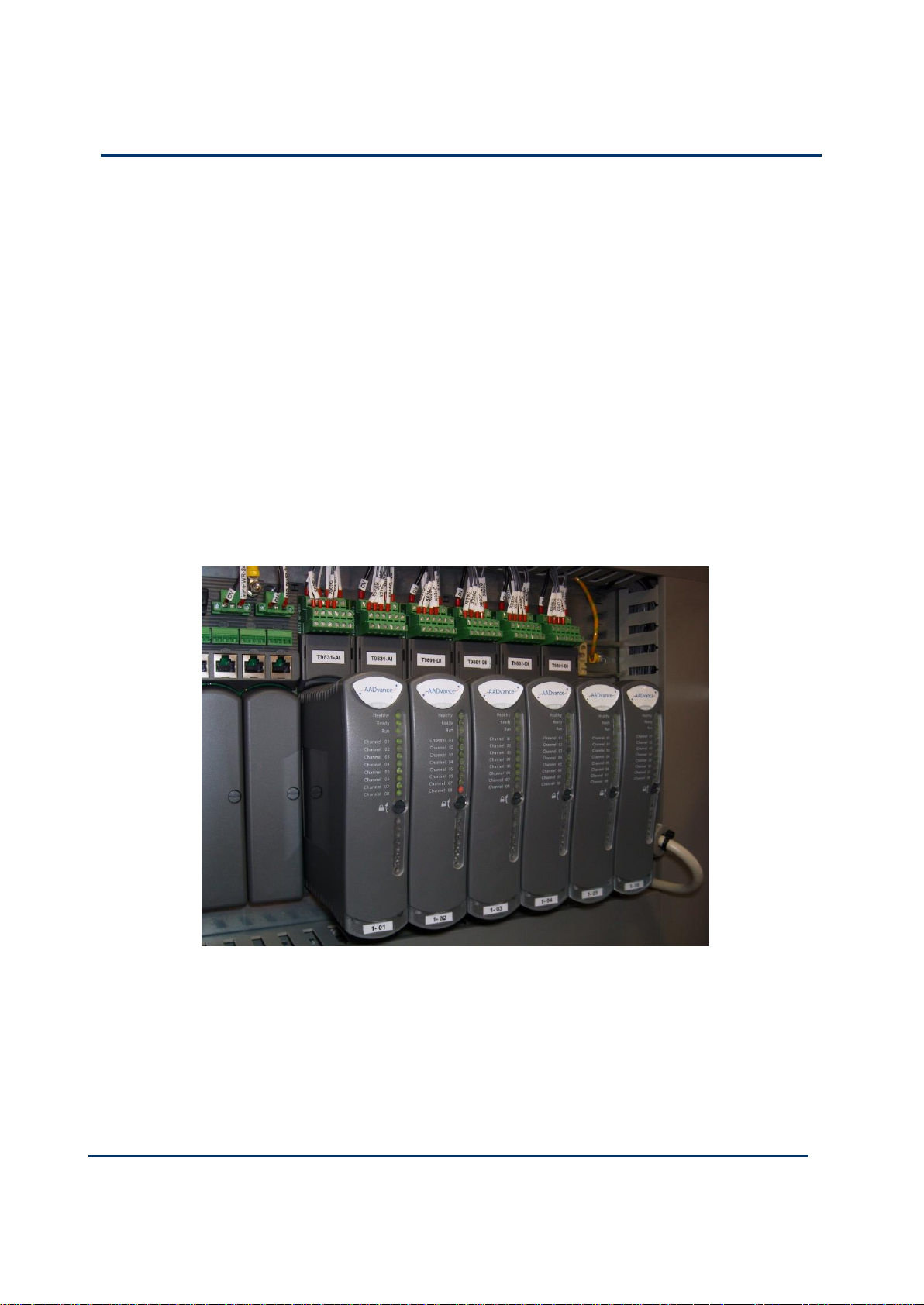
A controller is built from a range of compact plug-in modules that are straightforward
to assemble into a system. They can be mounted onto DIN rails in a cabinet (see
photograph) or directly mounted onto a wall in a control room. They do not require
forced air cooling or special environmental control equipment. However, certain
consideration to the cabinet type must be applied when used in hazardous
environments.
A secure network communications protocol, developed by Rockwell Automation for
the AADvance system, permits distributed control using new or existing network
infrastructure while ensuring the security and integrity of the data. Individual sensors
and actuators can connect to a local controller, minimizing the lengths of dedicated
field cabling. There is no need for a large central equipment room; rather, the
complete distributed system can be administered from one or more PC workstations
placed at convenient locations.
Page 15

Document: 553631
(ICSTT-RM447J_EN_P) Issue: 09:
1-3
Single input modules are designed to meet SIL3 and in the most basic simplex
Attribute
Value
Functional Characteristics
Number of processor modules
1 (non-safety applications, SIL1 and SIL2 safety
applications)
2 (SIL3 applications)
3 (SIL3 fault tolerant and TMR applications)
Maximum number of I/O modules
48 modules (16 base units) - Two I/O busses each
holds 24 modules (8 I/O base units)
External interfaces
Network (10/100BASE-TX Ethernet)
Serial data communications (RS-485)
Inter-controller links
High integrity communications using Safety Network
Control Protocol (SNCP)
Application software support
All IEC 61131 languages
Displays
Status LEDs on each module
User controls
Fault Reset button on each processor module
Security
Plug-in "Program Enable" key for access to application
project and system configuration tools.
Mounting
DIN rail or flat panel
Performance Characteristics
Safety integrity level
IEC 61508 SIL2
IEC 61508 SIL3
(depending on processor and I/O module
configuration)
Sequence of Event
Processor Module (for internal
variables)
Event Resolution
Time Stamp Accuracy
Digital Input Module
Event Resolution
1ms
Application Scan
1ms
configuration they offer a fail-safe solution. The AADvance system has comprehensive
built-in diagnostics, while maintenance activities are straight forward operations which
maximize system availability.
The AADvance controller is developed and built for IEC 61131 compliance and
includes support for all five programming languages. Program access is secured by a
removable "Program Enable" key. Simulation software lets you prove a new application
before reprogramming and downloading, again maximizing system uptime.
Performance and Electrical Specifications
Table 1: Performance and Electrical Specifications
Page 16
1-4
Document: 553631
(ICSTT-RM447J_EN_P) Issue: 09:
Solutions Handbook (AADvance Controller)
Time Stamp Accuracy
10ms
Safety accuracy limit
200µA for Analogue Inputs and 1.0V dc for Digital
Inputs.
Electrical Characteristics
Supply voltage
Redundant 24V dc nominal, 18V dc to 32V dc range
Channel isolation (channel to channel
and channel to chassis)
Maximum withstanding
± 1.5kV dc withstand for one minute.
Module
Scan Time
T9401 Digital input module, 24V dc, 8 channel
Single
Dual
Triple
1.23ms
1.73ms
2.08ms
T9431 Analogue input module 24V dc, 8 channel
Single
Dual
Triple
1.26ms
1.91ms
2.33ms
T9451 Digital output module, 24V dc, 8 channel
Single
Dual
1.43ms
2.44ms
AADvance Workbench Sleep Period
57.2ms
Scan overhead per module
0.09ms
Scan Times
Power consumption, heat dissipation and weight depend on the arrangement of the
controller. You can estimate these values when you specify the controller using the
tables provided in this manual.
A typical module surface temperature measured against a processor module is 43°C ±
2°C.
The following scan times were taken from a test system consisting of production
modules.
The tests did not measure the effect of logic complexity and communications loading.
The scan time is:
(Number of module groups x scan time shown above) + Sleep Period + (Total
modules x scan overhead)
The scan time will vary by up to +/- 5ms (not including the effect of logic and
communications).
Page 17

Document: 553631
(ICSTT-RM447J_EN_P) Issue: 09:
1-5
Throughput time is the time from input change to output action. Due to the discrete
Attribute
Value
Operating Temperature Range:
For use in Hazardous Environments (UL
Certification):
Processor Modules
I/O Modules and Assemblies
For use in Non-Hazardous Environments
(TUV Certification)
All Modules and Assemblies
–25 °C to 60 °C (–13 °F to 140 °F)
–25 °C to 70 °C (–13 °F to 158 °F)
–25 °C to 70 °C (–13 °F to 158 °F)
Storage and Transport Temperature
–40 °C to 70 °C (–40 °F to 158 °F)
Module Surface Temperature (during normal
operation)
43° C (109 °F) ± 2 °C
Humidity
Operating
10% to 95% RH, non-condensing
Storage and Transport
10% to 95% RH, non-condensing
Vibration
nature of the scan, the throughput time will vary between one and two scans.
Note: The AADvance application scan time is limited to a minimum of 64ms to allow
all processes to run. Small applications will report a scan time of approximately 57 61ms. Large applications may have longer scan times but each scan time will be
consistent to within approximately 5ms.
An example configuration scan time:
T9431 Analogue input simplex modules x 30
T9451 Digital output simplex modules x 18
Total I/O modules = 48
Estimated scan time = (30 x 1.23ms) + (18 x 1.43ms) + 57.2ms + (48 x 0.09ms)
= 125.1ms
Throughput time:
min = 125.1ms
Avg = 187.6ms
Max = 250.1ms
Environmental Specifications
The following environmental specification defines the minimum recommended
environmental conditions for an AADvance controller installation. Additional
conditions apply to installations in a Hazardous environment.
Table 2: Environmental Specification
Page 18

1-6
Document: 553631
(ICSTT-RM447J_EN_P) Issue: 09:
Solutions Handbook (AADvance Controller)
Functional Stress
5Hz to 9Hz
Continuous
1.7mm amplitude
Occasional
3.5mm amplitude
Withstand
10Hz to 150Hz
Acceleration
0.1g in 3 axes
Endurance
10Hz to 150Hz
Acceleration
0.5g in 3 axes
Shock
15g peak, 11ms duration, ½ sine
Altitude
Operating
0 to 2000m (0 to 6,600 ft.)
Storage and Transport
0 to 3000m (0 to 10,000 ft.)
This equipment must not be transported in
unpressurized aircraft flown above 10,000 ft.
Electromagnetic Interference
Tested to the following standards: EN 613261:2006, Class A; EN 61326-3-1:2008, EN 54-4:
1997, A1; EN 61131-2:2007; EN 62061:2005.
Hazardous Location Capability
Suitable for Class I Div 2 and Zone 2
Note:
Casing: Standard AADvance modules also have a plastic casing and are rated IP20:
Protected against solid objects over 12mm (1/2in.) for example "fingers". There is no
specific protection against liquids.
Page 19

Document: 553631
(ICSTT-RM447J_EN_P) Issue: 09:
1-7
IEC 61508, Part 1-7:1998-2000
EN 50178:1997
IEC 61511-1:2004
EN 50156-1:2004
EN 61131-2:2007
EN 54-2:1997, A1:2006 (†)
EN 61326-3-1:2008
NFPA 72:2007
EN 61000-6-2:2005
NFPA 85:2007
EN 61000-6-4:2007
NFPA 86:2007
Controller TUV Certification
TÜV Certification
TÜV is the safety certifying authority for an AADvance controller. The AADvance
system is certified to the following standard:
(†) The analogue output modules are not certified to EN 54-2.
You can download a copy of the TUV certificate from www.tuvasi.com.
The Euro Controller version of the AADvance product is also tested to Q1 Extended
Design levels of ISO 13628-6: 2006 Sub Sea Production Control System.
Certification for use in Hazardous Environments
The AADvance controller has been investigated and approved by UL (UL508) for use
as Industrial Control Equipment in a general industrial environment and for use in
hazardous locations, Class I, Division 2, Groups A, B, C and D. The UL file numbers
are: E341697 and E251761.
File No: E341697
The AADvance controller investigation and approval is contained in the following files:
NRAQ.E341697: Programmable Controllers investigated to ANSI/UL 508.
The products have been investigated using requirements contained in the following
standards:
UL508, Industrial Control Equipment, Seventeenth edition, with revisions through
and including April 15, 2010.
NRAQ7.E341697: Programmable Controllers Certified for Canada
The products have been investigated using requirements contained in the following
standards:
CSA C22.2 No 142-M1987, Process Control equipment, Edition 1 - Revision date
1990-09-01
Page 20

1-8
Document: 553631
(ICSTT-RM447J_EN_P) Issue: 09:
Solutions Handbook (AADvance Controller)
Products Covered
The products investigated and approved:
Programmable Logic Controllers Models: 9110 Processor Module; 9401/2 Digital
Output Module; 9431/2 Analogue Input module; 9451 Digital output module; 9482
Analogue Output Module.
Listed Accessories for use with PLCs: 9100 Processor Backplane, 9300 I/O Backplane,
9801 Digital Input Termination Assembly, Simplex; 9802 Digital Input Termination
Assembly, Dual; 9803 Digital Input Termination Assembly, TMR; 9831 Analogue input
Termination Assembly, Simplex; 9832, Analogue Input Termination Assembly, Dual;
9833 Analogue Input Termination Assembly, TMR 9851 Digital Output Termination
Assembly, Simplex and 9852 Digital Output Termination Assembly, Dual; 9881
Analogue Output Termination Assembly, Simplex; 9882 Analogue Output Termination
Assembly, Dual.
File No: E251761
The AADvance controller investigation and approval is contained in the following file
certifications:
NRAG.E251761: Programmable Controllers for Use in Hazardous Locations Class I,
Division 2, Groups A, B, C and D.
The products have been investigated using requirements contained in the following
standards:
ANSI/ISA 12.12.01-20007, Nonincendive Electrical Equipment for use in Class I and
UL508, Industrial Control Equipment, Seventeenth edition, with revisions through
II, Division 2 and Class III, Division 1 and 2 Hazardous Locations.
and including April 15, 2010.
NRAG7.E251761: Programmable Controllers for Use in Hazardous Locations
Certified for Canada; Class I, Division 2, Groups A, B, C and D
The products have been investigated using requirements contained in the following
standards:
CSA C22.2 No 213-M1987, Nonincendive Control Equipment for Use in Class I,
CSA C22.2 No 142-M1987, Process Control equipment, Edition 1 - Revision date
Products Covered
The products investigated and approved:
Programmable Logic Controllers Models: 9110 Processor Module; 9401/2 Digital
Output Module; 9431/2 Analogue Input module; 9451 Digital output module; 9482
Analogue Output Module.
Division 2, Hazardous Locations.
1990-09-01
Page 21

Document: 553631
(ICSTT-RM447J_EN_P) Issue: 09:
1-9
Listed Accessories for use with PLCs: 9100 Processor Backplane, 9300 I/O Backplane,
9801 Digital Input Termination Assembly, Simplex; 9802 Digital Input Termination
Assembly, Dual; 9803 Digital Input Termination Assembly, TMR; 9831 Analogue input
Termination Assembly, Simplex; 9832, Analogue Input Termination Assembly, Dual;
9833 Analogue Input Termination Assembly, TMR 9851 Digital Output Termination
Assembly, Simplex and 9852 Digital Output Termination Assembly, Dual; 9881
Analogue Output Termination Assembly, Simplex; 9882 Analogue Output Termination
Assembly, Dual.
Page 22
1-10
Document: 553631
(ICSTT-RM447J_EN_P) Issue: 09:
Solutions Handbook (AADvance Controller)
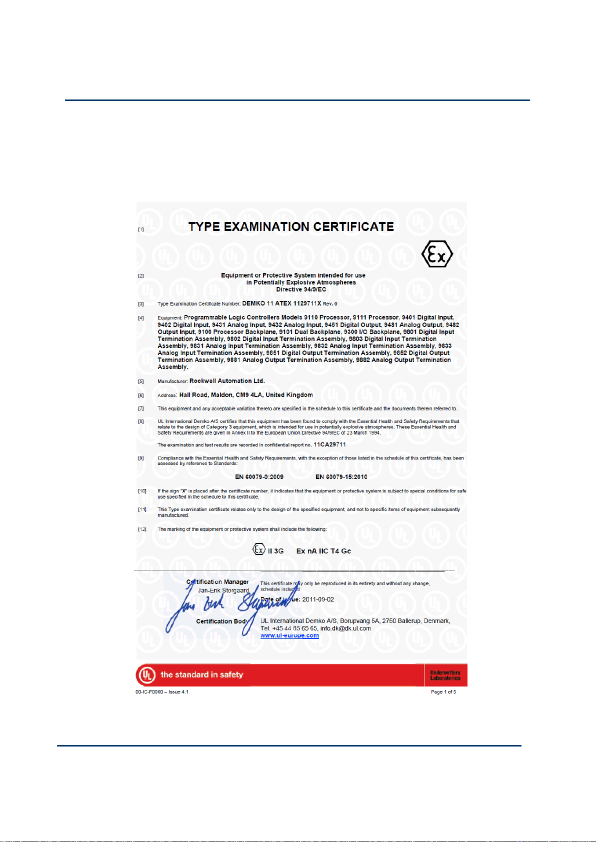
Certificate
The AADvance controller modules have been evaluated to the requirements of EN
60079-0: 2009 and EN 60079-15: 2010 under Certificate Number: DEMKO 11 ATEX
1129711X .
Page 23

Document: 553631
(ICSTT-RM447J_EN_P) Issue: 09:
1-11
Module label
The AADvance controller has also been evaluated under certificate IECEx UL
12.0032X to the standards IEC 60079-0; (5th Edition) and IEC 60079-15 (4th Edition).
[ certificate to be supplied]
For a system that is located in a Zone 2 Hazardous environment where ATEX
certification is required, all modules should be installed in an ATEX and IECEx
Certified, tool accessible IP54 enclosure. The enclosure is to be marked with the
following: "Warning - Do not open when energized". After installation of the modules
into the enclosure, access to termination compartments shall be dimensioned so that
conductors can be readily connected. The modules and assemblies are for use in an
area of not more than pollution degree 2 in accordance with IEC 60664-1
Page 24
1-12
Document: 553631
(ICSTT-RM447J_EN_P) Issue: 09:
Solutions Handbook (AADvance Controller)
KCC-EMC Registration
KCC- EMC Registration
Page 25

Document: 553631
(ICSTT-RM447J_EN_P) Issue: 09:
1-13
Main Components
Hardware Components
Each controller is built from a standard range of modules and assemblies; it consists of
processor modules, a processor base unit, digital and analogue I/O modules, I/O base
units and termination assemblies all of which are assembled as follows:
A processor module is installed into a processor base unit that can hold up to 3
processor modules.
3-way I/O base units are connected to the processor base unit and to each other.
Each I/O base unit holds up to three I/O modules and termination assemblies. A
controller can have up to 8 I/O base units on each of two I/O busses, giving a total
capacity for up to 48 I/O modules.
I/O modules are connected to field devices through external connectors on the
termination assemblies.
The processor module and base units are designed for use as either single, dual or
triple redundant processor module arrangements. The base processor base unit
provides external connections for Serial and Ethernet networks and the dual
redundant system power inputs.
The I/O base unit plugs directly into the processor base unit and carries the redundant
system power for the modules, the processor commands across a command bus and
I/O data across individual data response busses.
I/O base units also directly plug into each other and are secured and held in place by a
clamping arm and retaining clips; hence, a controller becomes a complete mechanically
and electrically interconnected assembly without the need for additional wiring or
cabling. The I/O modules are also designed for use in single or dual or triple redundant
configurations.
Termination assemblies are matched to a specific type of I/O module and have terminal
blocks that provide 8 or 16 connections for the wiring to the field elements. The
termination assemblies for dual and triple arrangements have channel to channel
isolation. Termination assemblies for simplex input modules and termination
assemblies for simplex and dual output modules are single ended (non-isolated) with a
common return.
An expansion cable can be used to connect the processor base unit or an I/O base unit
to another I/O base unit. This is useful for to breaking long runs of interconnected
base units and provides some flexibility in the physical layout of a controller
installation, particularly if the controller is installed in a cabinet.
Page 26

1-14
Document: 553631
(ICSTT-RM447J_EN_P) Issue: 09:
Solutions Handbook (AADvance Controller)
AADvance Workstation Software and Application Development Environment
Workstation Software
The AADvance workstation uses software that enables you to design the complete
control strategy as one, then to target parts of the strategy at each controller.
Interaction between the resources is automatic, significantly reducing the complexity of
configuration in a multi-resource solution.
The workstation software, known as the Workbench is compliant with IEC61131
industrial standard and has the following powerful features:
the regulation of the flow of control decisions for an interacting distributed control
system
providing for the consistency of data
providing a means for synchronous operation between devices
eliminating the need to have separate synchronous schemes
easing the development and maintenance of robust systems
The Workbench lets you create local and distributed control applications using the
five languages of IEC 61131-3. Engineers can choose one language or a combination of
languages that best suits their knowledge and programming style and the nature of the
application.
It is also a secure development environment that requires a hardware (USB Dongle) or
software license to run on a PC. There is also a Program Enable key (not applicable
to a Euro Controller) that must be plugged into the processor base unit to allow the
user to modify and download the application resource or access the
AADvanceDiscover utility to check the status of the controller IP address. The
Program Enable key when it is removed protects the application from unauthorized
access.
The development environment includes:
tools for program development
program documentation
function block library management
application archiving
database configuration
import/export utilities
on-line monitoring
off-line simulation and controlled on-line changes.
Page 27
Document: 553631
(ICSTT-RM447J_EN_P) Issue: 09:
1-15
Programs can be simulated and tested and tested on the computer before downloading
CAUTION
WORKBENCH FOR USE IN SAFETY APPLICATIONS
If the Workbench is used for safety related applications then you must follow
the guidelines given in the AAdavnce Safety Manual (Doc No: 553630).
CAUTION
WORKBENCH OPERATING SYSTEM
Do not use XP Professional x64 edition.
to the controller hardware. Also provided is a set of configuration tools that enables
you to define the hardware architecture in the software; set up the processor
functionality; and connect application variables to the Workbench application
resource program that will monitor processor and I/O module status information and
report I/O channel data values to the Workbench. Resource Control applications can
be distributed across several hardware platforms, communicating with each other
through secure networks.
Operating System
The 9110 Processor Module must have an operating system with the following
specification:
Windows XP with Service Pack 3
Windows Vista, Windows 7 & Server 2003 in both 32-bit and 64-bit versions
Note: Work Bench Licensing –Windows 64-bit version will only work with the
USB Licensing option (dongle option).
Network port (10/100 Base T Ethernet)
Access to a CD-ROM drive, for software installation
Note: If the application adopts the USB (dongle) licensing option for the
Workbench software, the processor module will also require one free USB port.
AADvanceDiscover Utility
The AADvanceDiscover utility is installed when you install the
<DevelopmentSoftwareTools>, and appears on the Start menu of the computer. it
displays a list of the <ProductName> controllers on the broadcast network, and
reports a status for each one.
Importing and Exporting Data
The AADvance Workbench can import and export existing data in standard file
formats such as Microsoft Excel.
Page 28

1-16
Document: 553631
(ICSTT-RM447J_EN_P) Issue: 09:
Solutions Handbook (AADvance Controller)
Controller Functionality
SNTP
The AADvance controller supports the Simple Network Time Protocol (SNTP)
service that can circulate an accurate time around the network. As an SNTP client the
controller will accept the current time from external Network Time Protocol
(NTP) and SNTP network time servers.
SNTP clients settings tell the controller the IP address of the external server; the
version of SNTP offered by the server; and the operating mode for the time
synchronization signal that the processors will use for their real time clock.
An AADvance controller can also fulfill the role of one or more SNTP servers (one for
each processor) to provide a network time signal throughout the network. To enable
server time on an interface it is necessary to specify the direct broadcast address for
that interface. This works for broadcast or unicast modes. This method of configuring
is derived from the NTP configuration command language.
CIP over EtherNet/IP
The Common Industrial Protocol (CIP) over EtherNet/IP protocol enables
AADvance controllers to exchange data with ControlLogix controllers programmed
by RSLogix 5000. The exchange of data uses the produce/consume tag method
currently used for sharing data between Logix-based controllers; this mechanism is
similar to the variable bindings mechanism used by the AADvance controller.
The AADvance controller supports produce and consume communications to
redundancy systems. The support for produce/consume variables is non-interfering; a
failure of the EtherNet/IP stack will not interfere with the safe operation of the
controller.
To use CIP over EtherNet/IP you have to first define a CIP network. Then you
configure the exchange of data by defining a produce variable (or structure) for
AADvance controller and a corresponding consume variable (or structure) for the
ControlLogix controller. At runtime, the controller with the consume variable pulls
data from the controller with the produce variable.
Note: The AADvance Controller will support the following number of connections
and variables:
Connections: Maximum 255
A maximum of 128 producer and 128 consumer variables can be defined.
Page 29

Document: 553631
(ICSTT-RM447J_EN_P) Issue: 09:
1-17
Note: The CIP Protocol is intended to allow AADvance users to exchange data
between AADvance controllers and the Allen Bradley Logix family controllers, using
produce/consume messaging. Produce/Consume messaging does not support
downloading to or for monitoring AADvance controllers. It is not recommended to
use the CIP network to exchange data between AADvance controllers unless this is
exclusively for non-safety data. The SNCP network should be used for Safety related
data exchange between AADvance Controllers (see SNCP and variable Bindings in this
publication).
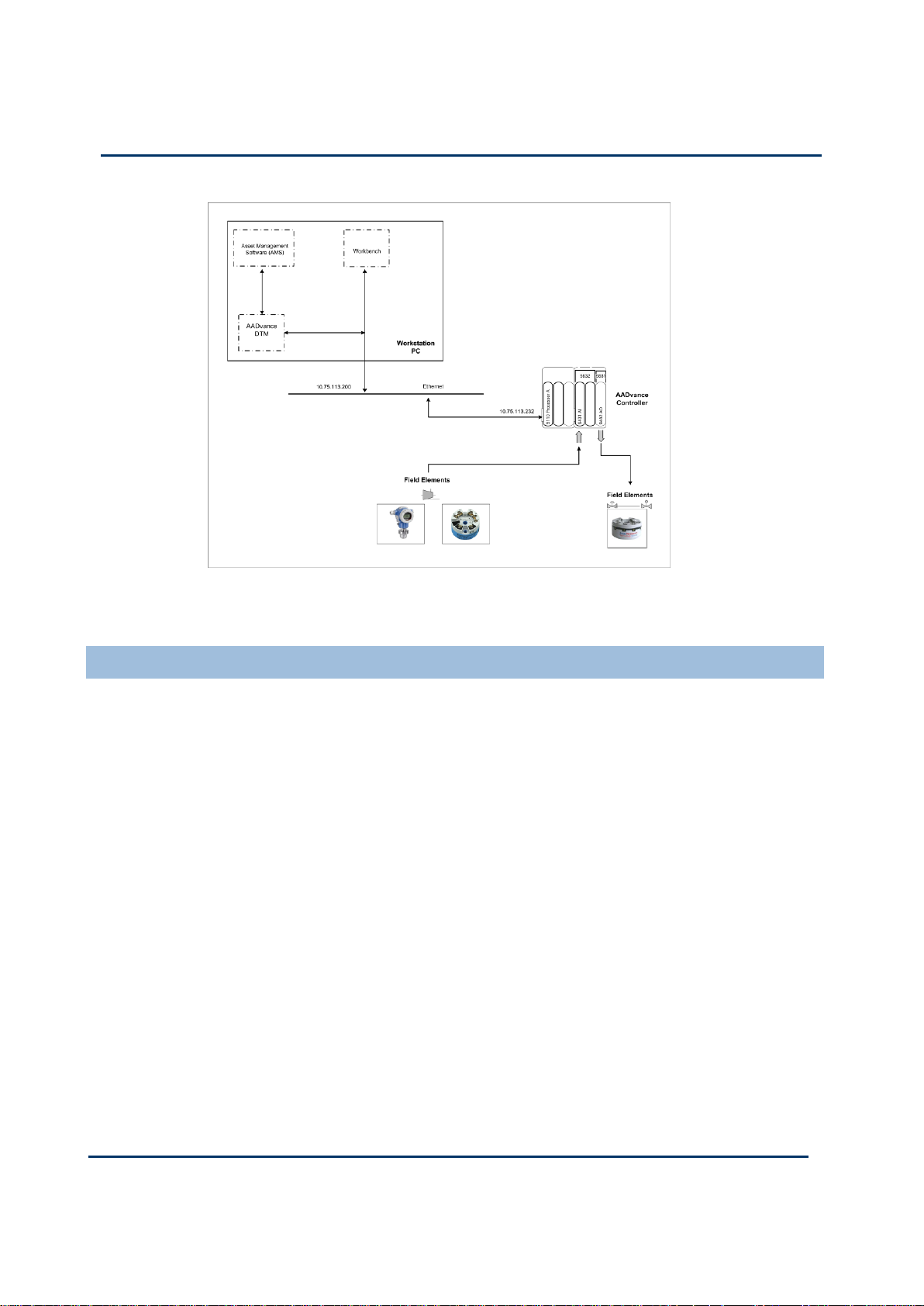
HART
The AADvance controller supports utilizing dedicated HART modems on each
analogue input and output channel allowing HART field device status, diagnostics and
process data to be integrated into the application logic, thus increasing the level of SIF
diagnostics significantly.
The AADvance analogue input/output modules use HART commands #03 to collect
data from the field device as defined by Revision 5 of the HART specification. The
application can be configured to use HART information to monitor and respond to
device conditions. It may also be used to provide diagnostic information such as
comparison and error reporting.
An additional feature of the AADvance controller is that it also combines with the
AADvance DTM to enable asset management software (ASM) to communicate with
HART devices.
Note: The AADvance system does not alter the messages passed between the asset
management software and the field device and acts as a transport mechanism only.
AADvance HART Features
Provides passthru support for HART Standards 5, 6 and 7.
Variables can be configured for each Analogue input and output channel to
monitor HART device information.
HART support is available on each Analogue Input or Output channel.
AADvance uses a single dedicated Ethernet port for HART passthru
communication.
Supports the AADvance DTM provided by Rockwell Automation.
A typical HART set up is shown below:
Page 30
1-18
Document: 553631
(ICSTT-RM447J_EN_P) Issue: 09:
Solutions Handbook (AADvance Controller)
Figure 1: Example HART Pass-through System
SNCP Safety Networks
SNCP (Safety Network Control Protocol) is the Safety Protocol that allows
elements of an AADvance System to exchange data. AADvance SNCP is a SIL 3
certified protocol which provides a safety layer for the Ethernet network making it a
"Black Channel". Data is exchanged by creating a relationship between variables in
different AADvance controllers; this is called "Binding Variables". Once variables are
bound between controllers the SNCP protocol provides a transparent SIL 3 Certified
layer allowing safety related data to be passed between AADvance controllers.
The bindings are based on a producer/consumer model. The controller consuming the
data establishes a binding link with the Controller producing the data, and manages the
entire exchange of data, including scheduling the data exchange, providing the
diagnostics, managing the safety response in the event of faults and managing the
communications redundancy.
SNCP Networks can be configured as Simplex (Fail Safe) or Redundant (Fault tolerant),
the choice of network configuration is dependent on the applications safety and
availability requirements. The data exchange is independent of the physical; network
configuration as the connection between the controllers is treated as a logical
network.
Page 31

Document: 553631
(ICSTT-RM447J_EN_P) Issue: 09:
1-19
The physical network is considered a "Black Channel" so the design of the Ethernet
network and the equipment used does not impact the SIL rating of the
communications interface, but the design of the network does affect the reliability of
the network and does impact the spurious trip rate. SNCP Network data can be
combined on a common network resulting in safety and non-safety data sharing in a
common physical network; this does not compromise the SIL rating of the network
but again does introduce failure modes and possibly security risks which can increase
the spurious trip rate, careful consideration should be given to the network topology
during the applications specification and design phase.
Page 32

1-20
Document: 553631
(ICSTT-RM447J_EN_P) Issue: 09:
Solutions Handbook (AADvance Controller)
Peer-to-Peer
AADvance provides the capability for a SIL 3 certified Peer-to-Peer data connections,
allowing safety data to be transferred between AADvance and Trusted Controllers.
The Trusted Peer-to-Peer network protocol enables you to share safety data between
AADvance systems or AADvance and Trusted
TM
systems across an Ethernet network.
Data can be transferred between individual systems or from one to several systems at
the same time using multicast network connections. Peer-to-Peer communication is
configured by defining a peer network controller and I/O devices within the application
program.
Note: AADvance currently supports multicast network connections on the left most
port only.
For safety related applications it is recommended that the Peer-to-Peer
communications use redundant networks (for availability) and separate networks (from
general purpose, for security and integrity). Any of the AADvance or Trusted ports
can be used for Peer-to-Peer data connections see Example shown.
The Trusted Peer-to-Peer protocol is a master/slave interaction. For each peer
communications subnet one system acts as a master while the others act as slaves.
During the Peer-to-Peer communication cycle the master sends a command to the
first slave to transmit its data. When the slave completes this task it acknowledges this
back to the master. The master repeats this with the next and all slaves in turn. Finally
the master transmits its own data then repeats the cycle with the slaves.
Page 33

Document: 553631
(ICSTT-RM447J_EN_P) Issue: 09:
1-21
Peer-to-Peer
Settings
TÜV Certified
Configuration
Conditions
Software Board
Definitions:
Dxpdi16
Dxpdo16
Dxpao16
Dxpdi128
Dxpdi128 & dxpnc40
Certified for use over
a single
communication
network or multiple
networks
Certified as safety-related and can be used for safety
critical communications in SIL 3 applications.
Safety Related Peer-to-Peer Configurations
The following Peer-to-Peer configurations are approved for use in a safety Related
Function:
Table 3:
Page 34

1-22
Document: 553631
(ICSTT-RM447J_EN_P) Issue: 09:
Solutions Handbook (AADvance Controller)
Peer-to-Peer
Settings
TÜV Certified
Configuration
Conditions
Software Board
Definitions:
Dxpai128
Dxpao128
Certified for use over
a single
communication
network or multiple
networks
Certified as safety-related and can be used for safety
critical communications in SIL 3 applications
provided to separate Dxpai128 & Dxpao128 board
definitions are used for safety values, the safety
values from the tw oDxpai128 boards (or digital trip
points from the values) shall have a 1oo2 vote
within the receiving application.
Serial Communication Interface
Two serial ports on each processor module support the following signal modes
depending upon use:
RS485fd: A four-wire full duplex connection that features separate busses for
transmit and receive. This selection should also be used when the controller is
acting as a Modbus master using the optional four-wire definition described in
Section 3.3.3 of the Modbus-over-serial standard.
RS485fdmux: A four-wire full-duplex connection with tri-state outputs on the
transmit connections. This should be used when the controller is acting as a
Modbus slave on a four-wire bus.
RS485hdmux: A two-wire half duplex connection appropriate for or master slave
or slave use. This is shown in the Modbus-over-serial standard.
Time Synchronization (SNTP)
The AADvance controller supports the Simple Network Time Protocol (SNTP)
service that can circulate an accurate time around the network. It can be configured to
operate as a SNTP client or server.
As an SNTP client the controller will accept the current time from external Network
Time Protocol (NTP) and SNTP network time servers. The SNTP clients settings
tell the controller the IP address of the external server; the version of SNTP offered
by the server; and the operating mode for the time synchronization signal that the
processors will use for their real time clock. As a client the processor module can be
configured as a unicast or broadcast client.
The AADvance controller can also fulfill the role of one or more SNTP servers (one
for each processor module) to provide a network time signal throughout the network.
To enable server time on an interface it is necessary to specify the direct broadcast
address for that interface. This works for broadcast or unicast modes and when
configured as a broadcast server it can respond to Unicast requests from clients.
Note: To set up SNTP you need to connect your controller to a suitable network
using one of the Ethernet ports. The network must be connected to an external NTP
server or have NTP loaded on to it.
Page 35

Document: 553631
(ICSTT-RM447J_EN_P) Issue: 09:
1-23
Modbus Master
The AADvance controller can be used as a Modbus master to one or more Modbus
slave devices. Slave devices can include programmable logic controllers, remote devices
(typically with little or no processing capability) and, more rarely, other functional
safety controllers (Trusted or AADvance).
The controller supports the Modbus RTU and Modbus TCP protocols, and a subset
of Modbus commands. You can use Modbus RTU with point-to-point and multi-drop
serial links, and Modbus TCP with Ethernet.
Note: The AADvance controller does not support the Modbus ASCII protocol.
You can set up an individual list of messages (commands) for each slave device.
Modbus read commands cause data to read from the slave device to the Modbus
master, while Modbus write commands cause data to be copied from the Modbus
master to the slave device. You can also define a sequence of broadcast write
commands, which a Modbus master can send to multiple Modbus RTU slaves without
requiring an acknowledgement. The AADvance controller can control and monitor
individual Modbus master objects and their slave links.
The Modbus master functionality has a safety integrity level of zero (SIL0) and should
only be used for non-safety applications.
Page 36

1-24
Document: 553631
(ICSTT-RM447J_EN_P) Issue: 09:
Solutions Handbook (AADvance Controller)
Modbus Master Hardware and Physical Connections
The Modbus master functionality is built into the T9110 Processor Module; the
physical communication ports are located on the T9100 Processor Base Unit. You do
not need to add any extra hardware to the AADvance controller except to make the
physical connections to the processor base unit. The illustration shows some possible
arrangements of Modbus master connections.
The Modbus RTU slave devices are connected to one or more of the serial ports on
the controller; a typical arrangement will use a multi-drop (RS-485) arrangement. The
engineering workstation and the Modbus TCP devices are shown connected to the
Ethernet ports on separate networks; alternatively these can be combined onto one
network.
The OPC Portal Server
The OPC Portal Server is a windows-based application that allows OPC compatible
clients, such as HMIs and SCADA systems, to connect to one or more AADvance
controllers to access process data.
Page 37

Document: 553631
(ICSTT-RM447J_EN_P) Issue: 09:
1-25
Controller IP Address Setting
The AADvanceDiscover Utilility uses a discovery and configuration protocol
(proprietary to Rockwell Automation) to set the controller IP address within the
AADvance Workbench and to scan the broadcast domain for other AADvance
controllers. The utility locates each controller by its unique MAC Address. Having
located a particular controller to be configured, the utility lets you configure the
resource number and IP Address to be stored in the controller; after you have done
this, the AADvance Workbench can communicate with the other controller.
Recovery Mode
Recovery Mode is a shutdown mode and uses a base level firmware. It is entered
automatically when a critical firmware failure occurs or it can be entered manually by
pressing the processor Fault Reset button immediately after the module has booted
up. The Recovery Mode is also used when you want to download a new firmware
upgrade.
As an alternative firmware version it allows the following maintenance activities:
Update the firmware using the ControlFLASH utility
Program the processor IP Address with the AADvance Discover utility
Extract diagnostic information
Note: When in Recovery Mode the I/O communications are disabled and the
Application code is not running. The inputs and outputs will revert to their fail-safe
settings.
DiffServ Configuration
This option allows you to specify the priority of IP traffic and is particularly useful for
ensuring that high priority services are either not affected or less affected during
periods of network congestion.
When you set up this option you apply a priority value to a service and therefore
differentiate it from less important services. You can do this by setting a suitable
configuration of routers, or switches able to inspect IP headers and prioritize by the
Type of Service (ToS) header option. Network devices will then apply their rules to
prioritize IP traffic; AADvance simply maintains the priority when responding to
incoming messages and sets a priority according to the configuration for messages it
initiates.
Page 38

1-26
Document: 553631
(ICSTT-RM447J_EN_P) Issue: 09:
Solutions Handbook (AADvance Controller)
Ethernet Forwarding
When enabled, the "Ethernet Forwarding" feature will forward all Ethernet packets
destined for a host (3rd Party Device) connected to one of the AADvance’s Ethernet
ports along with any broadcast and multicast Ethernet traffic. Incoming messages on
the other port will be forwarded directly to the second. The forwarded messages will
be unaltered by the AADvance controller.
This feature can be enabled using the AADvance Discover utility. Packets intended for
the AADvance itself (i.e. the destination MAC address of the packet matches the
processor’s receiving port MAC address) as well as broadcasts and multicasts are still
sent to the AADvance application as normal.
Note: The Ethernet network carrying Safety Data on a Safety application is considered
to be a black channel, therefore, it is unaffected by this function. However, by
implementing Ethernet Forwarding you may be forwarding non-safety data onto a
safety network and could effectively bridge a safety and non-safety segregated network
through the AADvance.
Page 39

Document: 553631
(ICSTT-RM447J_EN_P) Issue: 09:
1-27
Transparent Communication Interface (TCI)
The AADvance controller processor module provides a Transparent Communications
Interface (TCI) function. This functionality will establish a pass-through
communications link between an Ethernet link to a Serial port allowing devices
attached to a serial port to be communicated with and for them to reply. The
controller does not tamper with or inspect the data passed over the channel.
TCI uses a TCP port number to represent a serial port. All six serial ports are
represented by each controller, so any serial port can be reached from any controller.
Traffic is routed through TCP to the relevant serial port and in reverse. However, TCI
communication from the serial ports is only available when the controller is not
executing an application.
Users can enable and disable the function and set the Inactivity Timeout and Idle Time
values.
Important Note: To use the TCI function you must stop the resource. This will
have a serious effect on a Safety Related application.
Compiler Verification Tool
The Compiler Verification Tool (CVT) is a software utility that validates the output of
the application compilation process. It is automatically enabled for resources when a
project is created and when you add a resource to an existing project. This process in
conjunction with the validated execution code produced by the AADvance
Workbench confirms that there are no errors introduced by the Compiler during the
development of the application.
To achieve this CVT decompiles the application project file and then compares each
individual application project (POU) source files with its decomposed version. The
CVT analysis is displayed in the Workbench window.
Page 40

1-28
Document: 553631
(ICSTT-RM447J_EN_P) Issue: 09:
Solutions Handbook (AADvance Controller)
Technical Features
TUV Approved Operating System
The AADvance system runs an IEC 61508 approved operating system and the overall
system is certified to IEC 61508, Part 1-7: 19T98 - 2000 SIL3.
Internal Diagnostics
The AADvance controller contains comprehensive internal diagnostic systems to
identify faults that develop during operation and raise appropriate alarm and status
indications. The diagnostic systems run automatically and check for system faults
associated with the controller, and field faults associated with field I/O circuits.
Serious problems are reported immediately, but faults on non-essential items are
filtered to avoid spurious alarms. The diagnostic systems monitor such non-essential
items only periodically, and need a number of occurrences of a potential fault before
reporting it as a problem.
The diagnostic systems use simple LED status indications to report a problem. The
LED indications identify the module and can also identify the channel where the fault
has occurred. There is also a summary system healthy indication for the whole
controller.
The application software uses its variable structures to report a problem; these
variables proved status reports and are configured using the AADvance Workbench.
A Fault Reset button on each processor module serves to clear a fault indication.
However, the diagnostic systems will report a serious problem again so quickly there
will be no visible change in the status indications. Pressing the Fault Reset button when
no fault is indicated has no effect.
Controller Internal Bus Structure
Internal communication between the processor modules and I/O modules is supported
by command and response busses that are routed through the processor and I/O base
units.
The processor modules acts like a communications master, sending commands to its
I/O modules and processing their returned responses. The two command busses IO
Bus 1 and IO Bus 2 carry the commands from the processor to the I/O modules on a
multi-drop basis. An inter-processor link (IPL) provides the communication links
between dual or triple processor modules.
Each I/O module has a dedicated response line back to the processor. The unique
response line for each I/O module provides an unambiguous identification of the
source of the I/O data and assists with fault containment.
Page 41

Document: 553631
(ICSTT-RM447J_EN_P) Issue: 09:
1-29
System Modification and On-line Updates
The AADvance controller has a modular design which allows you to change the I/O
hardware configuration. An on-line update feature also allows you to make the
required changes to the workbench I/O configuration.
The following changes can be made by an on-line update:
Add new I/O base units, termination assemblies and extra I/O modules.
Delete modules from the system
Change the size of a termination assembly to change the configuration to
either increase the size or reduce the size of the module configuration.
Move a module to a different slot.
Change the variables for an I/O configuration change.
Making on-line changes after the system has been commissioned is the responsibility of
users and can have safety integrity implications the safety guidelines in the Safety
Manual need to be consulted before doing an on-line update.
On-line modifications must follow the end users' MOC process as required by the
applicable industry safety standards. On-line modifications must include any specific
checks recommended by Rockwell Automation for the product.
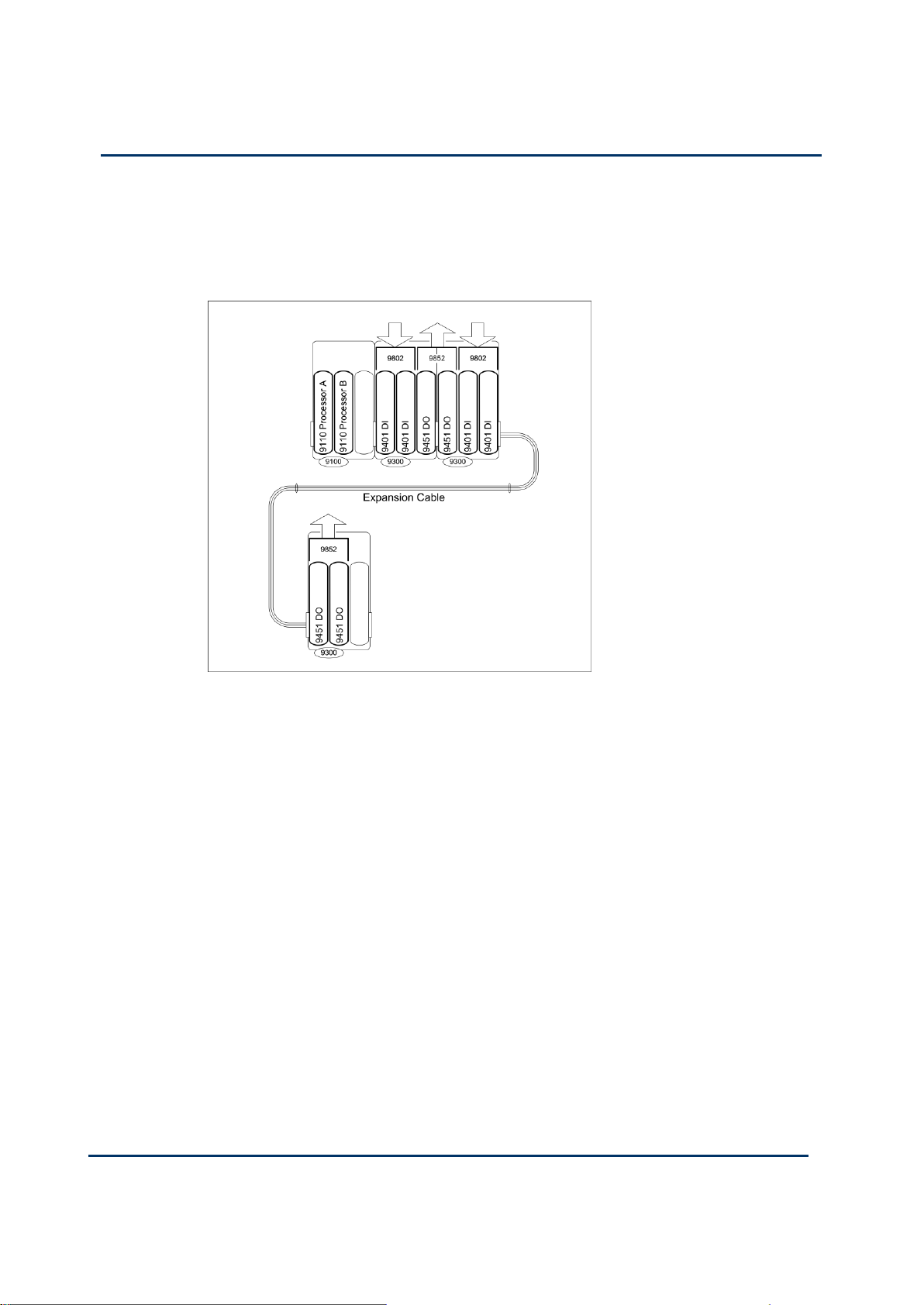
Expansion Cable
NOTE: If you are still using an earlier product release the I/O module configuration
cannot be changed with an on-line update.
Page 42
1-30
Document: 553631
(ICSTT-RM447J_EN_P) Issue: 09:
Solutions Handbook (AADvance Controller)
When new I/O modules need to be added and there is not enough space in the
existing row of modules, you can use an Expansion Cable to install a new row of
modules. A typical arrangement using an expansion cable is shown below.
Page 43

Document: 553631
(ICSTT-RM447J_EN_P) Issue: 09:
1-31
ControlFLASH Firmware Upgrades
WARNING
FIRMWARE UPGRADE DANGER TO A RUNNING SYSTEM
Do not attempt to upgrade firmware on a running system. Control
FLASH will not warn you that a system is running and you will lose
control of the application when the system reboots.
The AADvance controller supports upgrades of processor module firmware by using
the ControlFLASH utility. You need the ControlFLASH firmware upgrade kit that
includes and RSLinx Classic Lite software or better. To install and configure the
ControlFLASH utility refer to the Rockwell Automation ControlFLASH Firmware
Upgrade Kit documentation, Publication No: 1756-UM105C-EN-E March 2012
available from the Rockwell Automation Literature Library. This document defines
what you will need to carry out the procedures.
Note: I/O module upgrades using ControlFLASH are not currently supported in this
release.
Upgrading the processors is a two stage process:
Stage 1: Run the 350720_102_ControlFLASH.msi program to install the
ControlFLASH firmware upgrade kit for the Recovery Mode on your PC. Then
run the ControlFLASH utility to upgrade your processor module and install the
Recovery Mode. If your module is delivered with the Recovery Mode installed then
this stage is not necessary.
Stage 2: Reboot the processor and enter the Recovery Mode. The run
354400_0199_ControlFLASH.msi program to install the ControlFLASH to
upgrade your processor's OS, FPGA, LSP and BUSP.
Page 44

1-32
Document: 553631
(ICSTT-RM447J_EN_P) Issue: 09:
Solutions Handbook (AADvance Controller)
Attribute
Value
Base unit dimensions (H × W × D), approx.
233 × 126 × 18mm (see text)
(9-¼ in × 5 × ¾ in)
Module dimensions (H × W × D), approx.
166 × 42 × 118mm
(6-½ in × 1-⅝ in × 4-⅝ in)
Physical Features
An innovative feature of the AADvance controller is the design of the hardware.
Everything fits together easily without any need for inter-module wiring.
Product Dimensions
Overall Dimensions of Modules with Base Units
Table 4: Summary of Dimensions
Page 45

Document: 553631
(ICSTT-RM447J_EN_P) Issue: 09:
1-33
The depth of the base unit (18mm) excludes the parts of the backplane connectors
that mate inside the module connectors. Adding the depth of module (118mm) to the
depth of the base unit gives the overall depth of the controller assembly, which is
136mm.
Module Dimensions
All modules have the same dimensions.
Compact Module Design
Each processor and I/O module is enclosed in a flame-retardant and impact-resistant
plastic cover. The cover is designed to assist ventilation and heat dissipation.
Processor and I/O modules fit onto a series of standardized base units. Base units are
securely held together by specially designed plastic clips which cannot corrode or
seize. Modules are retained by a locking latch accessible from the front panel, and
corrective maintenance activities need only a standard screwdriver.
Page 46

1-34
Document: 553631
(ICSTT-RM447J_EN_P) Issue: 09:
Solutions Handbook (AADvance Controller)
Base units are moulded from a similar material. Each base unit can be mounted onto
CAUTION
HEAT DISSIPATION AND ENCLOSURE POSITION
System and field power consumption by modules and termination assemblies is
dissipated as heat. You should consider this heat dissipation on the design and
positioning of your enclosure; e.g. enclosures exposed to continuous sunlight
will have a higher internal temperature that could affect the operating
temperature of the modules. Modules operating at the extremes of the
temperature band for a continuous period can have a reduced reliability.
standard DIN rails or directly onto a panel or wall. The moldings incorporate slots and
clamps for DIN rail mountings, and holes for screw fixing.
Module Polarization Keying
For each I/O Module there is a matched termination assembly set. The controller
incorporates module polarization keying to ensure they are matched when installed.
Modules have polarized sockets that align and mate with coding pegs located on the
termination assembly. The alignment of the sockets and pegs ensure only the matched
I/O module type can be fitted into each associated termination assembly and only a
processor can be installed on a processor base unit.
Page 47

Document: 553631
(ICSTT-RM447J_EN_P) Issue: 09:
1-35
Module Locking Mechanism
Each module carries a locking mechanism, which secures the module onto its base unit.
The locking mechanism is in the form of a clamp screw, visible on the front panel of
the module and engaged by a quarter turn of a flat blade screwdriver. The module
senses the locking mechanism position and notifies the controller accordingly. This acts
as an interlock device and prevents the module from going on-line when it is not in the
locked position.
Termination Assemblies
The AADvance system provides a range of termination assemblies to connect field
wiring to the I/O modules. A termination assembly is a printed circuit equipped with
screw terminal blocks for the field wiring (in some cases fuses) and connectors for the
plug-in I/O modules. Termination assemblies are matched to their relevant I/O
modules by the coding pegs and sockets and come in three types: simplex, dual or
triple. Therefore, they can accommodate one two or three I/O modules. Each
assembly provides connections for up to 16 channels but can accommodate 8 or 16
channel modules.
Termination assembly design gives the controller greater flexibility for building
redundant and fault tolerant systems. I/O module(s) plugged into its matched
termination assembly can provide simplex, dual or triple modular redundant
configurations.
The version illustrated is a simplex termination assembly for a digital input module.
The field wiring connectors are located to the left, the fuses have a cover (shown
open) and the module sockets are to the right.
Page 48

1-36
Document: 553631
(ICSTT-RM447J_EN_P) Issue: 09:
Solutions Handbook (AADvance Controller)
WARNING
FUSE REMOVAL or REPLACEMENT
When the controller is installed in a Hazardous environment do not remove or
replace a fuse when energized.
Part No: Digital Input Fuses T9901: No 396/TE5 50mA time lag fuse; UL 248-14, 125
V,T Leadfree; manufactured by Littlefuse.
Part No: Digital Output Fuses T9902: SMF Omni-Block, Surface Mount Fuse Block
154 010, with a 10A, 125V Fast Acting Fuse, Littlefuse.
Page 49
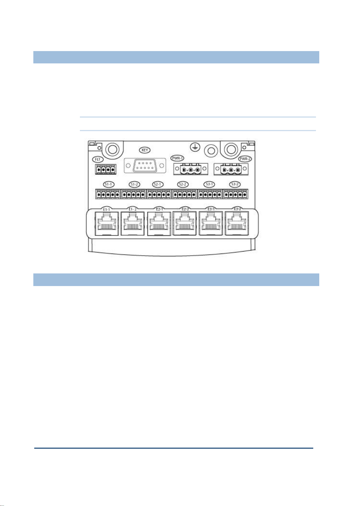
Document: 553631
(ICSTT-RM447J_EN_P) Issue: 09:
1-37
Ethernet, Serial Data and Power Connections
The external connections for Earthing, Ethernet (E1-1 to E3-2), serial data (S1-1 to
S3-2) and the +24V dc Redundant powers supplies (PWR-1 and PWR-2) are all
located on the T9100 Processor Base Unit. There are two serial data and two
Ethernet connectors for each processor module. Two connectors for the dual
redundant power supplies, a stud for the Earth and a connector for the security device
(KEY) also known as the Program Enable Key.
Note: The FLT connector is not used.
Serial Communications
The serial ports (S1-1 & S1-2, S2-1 & S2-2, S3-1 & S3-2) support the following
signal modes depending upon use:
RS485fd: A four-wire full duplex connection that features separate busses for
transmit and receive. This selection should also be used when the controller is
acting as a Modbus master using the optional four-wire definition described in
Section 3.3.3 of the Modbus-over-serial standard.
RS485fdmux: A four-wire full-duplex connection with tri-state outputs on the
transmit connections. This should be used when the controller is acting as a
Modbus slave on a four-wire bus.
RS485hdmux: A two-wire half duplex connection appropriate for or master slave
or slave use. This is shown in the Modbus-over-serial standard.
Page 50

1-38
Document: 553631
(ICSTT-RM447J_EN_P) Issue: 09:
Solutions Handbook (AADvance Controller)
Field Wiring Connections
Field connections are made using industry-standard screw terminal blocks. Terminals
are readily accessible for future wiring modifications without needing to dismantle any
assemblies. This illustration shows field wiring to four simplex termination assemblies:
Corrective Maintenance and Module Replacement
Corrective maintenance is by module replacement. In dual and triple modular
redundant configurations, you can remove a module and install a new one without
interrupting the system opetration. In simplex configurations removing a module will
interupt the system operation.
Field connection wiring is attached at the connectors on the termination assemblies.
Ethernet and Serial data connections are made at the T9100 Processor Base Unit.
There are no physical links needed to be set up on any modules or base units.
Standard modules are used for all the different configurations.
The guidelines for replacing modules are given in the AADvance Safety Manual (Doc
no 553630).
Note: Processor modules must be replaced with a module containing the same
firmware revision, you cannot use processor modules with different firmware
revisions.
Page 51

Document: 553631
(ICSTT-RM447J_EN_P) Issue: 09:
2-1
An AADvance controller can be configured to manage non-safety up to SIL 3 safety
In This Chapter
SIL2 Architectures .............................................................................................. 2-1
SIL3 Architectures .............................................................................................. 2-6
Planned Certified Configurations .................................................................. 2-11
Chapter 2
AADvance System Architectures
related system requirements and low demand or high demand fault tolerant
applications.
This chapter describes the different system architectures that can be configured for an
AADvance controller to meet this variety of requirements.
Note: Architectures are independent of I/O module capacity therefore 8 or 16
channel I/O modules can be used.
SIL2 Architectures
SIL2 architectures are recommended for fail-safe low demand applications. All SIL2
architectures can be used for energize or de-energize to trip applications. In any
configuration when a faulty processor or input module is replaced then the previous
fault tolerance level is restored. For example in a fault tolerant input arrangement and
one module is faulty then the system will degrade to 1oo1D, by replacing the faulty
module the configuration is restored to 1oo2D.
Definitions:
Low Demand Mode - in this mode the frequency of demands on the safety-related
system is no greater than twice the proof test interval. Where the proof test interval
refers to how often the safety system is completely tested and ensures it is fully
operational. For the AADvance System the default manual test interval is the value
used to calculate the PFH and PFD values.
High Demand Mode - sometimes called continuous mode, is where the frequency of
demands for operation made on a safety-related system is greater than twice the
manual test interval.
Page 52

2-2
Document: 553631
(ICSTT-RM447J_EN_P) Issue: 09:
Solutions Handbook (AADvance Controller)
SIL2 Fail-safe Architecture
Position
Module Type
I/P A
T9401/2 Digital Input Module, 24V dc, 8/16 Channel +
T9801 Digital Input TA, 16 Channel, Simplex. or
T9431/2 Analogue Input Module,
8/16 Channel +
T9831 Analogue Input TA, 16 Channel, Simplex
T9300 I/O Base Unit
CPU A
1 x T9110 Processor Module, T9100 Processor Base
Unit,
O/P A
T9451 Digital Output Module, 24V dc, 8 Channel,
isolated +
T9851 Digital Output TA, 24V dc 8 Channel, Simplex
The following is a simplex fail-safe SIL2 architecture, where I/O modules operate in
1oo1D under no fault conditions and will fail-safe on the first detected fault. The
processor module operates in 1oo1D and will degrade to fail safe on the first detected
fault.
Note: A simplex configuration can only be used for "low demand"
Table 5: Modules for SIL2 Fail-Safe Architecture
Page 53

Document: 553631
(ICSTT-RM447J_EN_P) Issue: 09:
2-3
SIL2 Fault Tolerant Input Architectures
Position
Module Type
I/P A and B
2 × T9401/2 Digital Input Module, 24V dc, 8/16 Channel +
T9802 Digital Input TA, 16 Channel, Dual or 2 × T9431/2
Analogue Input Module, 8/16 Channel, Isolated, + T9832
Analogue Input TA, 16 Channel, Dual
T9300 I/O Base Unit
CPU A
1 x T9110 Processor Module, T9100 Base Unit
O/P A
T9451 Digital Output Module, 24V dc, 8 Channel +
T9851 Digital Output TA, 24V dc, 8 Channel, Simplex
T9300 I/O Base Unit
A SIL2 fault tolerant input architecture can have dual or triple input modules with a
single processor and single output modules. The illustration shows a dual input
arrangement where the dual input modules operate in 1oo2D under no fault
conditions, they degrade to 1oo1D on detection of the first fault in either module of
the redundant pair, and when a fault occurs on the second module it will fail-safe.
The processor module operates in 1oo1D under no fault conditions and degrades to
fail safe on the first detected fault. The output module operates in 1oo1D under no
fault conditions and will fail-safe on the first detected fault.
When a triple input module arrangement is configured the group of input modules
operate in 2oo3D under no fault conditions, degrade to 1oo2D on the detection of
first fault in any module, then degrade to 1oo1D on the detection of faults in any two
modules, and will fail-safe when there are faults on all three modules.
Table 6: Modules for SIL2 Architecture
Page 54

2-4
Document: 553631
(ICSTT-RM447J_EN_P) Issue: 09:
Solutions Handbook (AADvance Controller)
SIL2 Output Architecture
Position
Module Type
I/P A
T9401/2 Digital Input Module, 24V dc, 8/16 Channel. +
T9801 Digital Input TA, 16 Channel, Simplex
or
T9431/2 Analogue Input Module, 8/16 Channel +
T9831 Analogue Input TA, 16 Channel, Simplex
T9300 Base Unit
CPU A
1 x T9110 Processor Module, T9100 Processor Base Unit
and 9300 I/O Base Unit
O/P A
1 × T9451 Digital Output Module, 24V dc, 8 Channel +
T9851 Digital Output TA, 24V dc, 8 Channel, Dual
A SIL2 output architecture has a single output module with single processor and single
or redundant input modules.
In de-energize to trip operation, the output modules operate in 1oo2D no fault
conditions and degrade to 1oo1D on detection of the first fault in either module
and fail-safe when there are faults on both output modules.
In energize to action operation, the output module operates in 1oo2D under no
fault conditions, degrade to 1oo1D on the detection of the first fault in either
module, and they fail-safe when there are faults on both modules.
The illustration shows a SIL2 single output arrangement where the output and
processor modules operate in 1oo1D under no fault conditions and will fail-safe on the
first detected fault.
Table 7: Modules for SIL2 Fault Tolerant Output Architecture
Page 55

Document: 553631
(ICSTT-RM447J_EN_P) Issue: 09:
2-5
SIL2 Fault Tolerant Input High Demand Architecture
A SIL2 fault tolerant "High Demand" architecture has dual input, dual processor and
dual output modules. In a dual arrangement the input modules operate in 1oo2D
under no fault conditions, degrade to 1oo1D on the detection of the first fault in
either module, and will fail-safe when there are faults on both modules.
A triple input module arrangement can also be configured if it is required to increase
the fault tolerance of the input. When a triple input module arrangement is configured
the input modules operate in a 2oo3D under no fault conditions, degrade to 1oo2D on
detection of the first fault in any module, then degrade to 1oo1D on the detection of
faults in any two modules, and will fail-safe when there are faults on all three modules.
The processor will operate in 1oo2D under non-faulted conditions and will degrade to
1oo1D on the first detected fault. For high demand applications the processor must be
repaired within the MTTR assumed in the PFD calculations or the high demand safety
instrumented functions must be shut down.
For High Demand applications you must use a minimum of a dual processor
configuration.
Table 8: Modules for SIL2 Fault Tolerant High demand Architecture
Page 56

2-6
Document: 553631
(ICSTT-RM447J_EN_P) Issue: 09:
Solutions Handbook (AADvance Controller)
Position
Module Type
I/P A
2 × T9401/2 Digital Input Module, 24V dc, 8/16 Channel +
T9802 Digital Input TA, 16 Channel, Dual or
2 × T9431/2 Analogue Input Module, 8/16 channel + T9832
Analogue Input TA, 16 Channel, Dual
2 × T9300 I/O Base unit
CPU A &
CPU B
2 x T9110 Processor,, T9100 Processor Base Unit
O/P A
2 × T9451 Digital Output Module, 24V dc, 8 Channel + T9852
Digital Output TA, 24V dc, 8 channel,
T9300 Base unit
SIL3 Architectures
SIL3 architectures have at least two processor modules and are suitable for use with:
SIL3 de-energize to trip applications
SIL3 energize to action applications when fitted with dual output modules
Faulted input modules in a SIL3 arrangement may be replaced without a time limit;
faulted output modules must be replaced within the MTTR assumed in the PFD
calculations.
In all SIL3 architectures, when the processor modules have degraded to 1oo1D on the
first detected fault, the system must be restored to at least 1oo2D by replacing the
faulty processor module within the MTTR assumed in the PFD calculations or all SIL3
safety instrumented function and high demand safety instrumented functions must be
shut down.
Page 57

Document: 553631
(ICSTT-RM447J_EN_P) Issue: 09:
2-7
SIL3 Fail-safe I/O, Fault Tolerant Processor
A SIL3, fail-safe I/O with a fault tolerant processor architecture has a simplex input and
output arrangement with dual or triple processor modules. The dual processor
modules operate in 1oo2D under no fault conditions and degrade to 1oo1D on
detection of the first fault in either module. When there are faults on both modules
the configuration will fail-safe.
If required you can configure triple processor modules as a variation of this SIL3
architecture. Using this arrangement the processor modules operate in 2oo3D under
no fault conditions and 1oo2D on the detection of the first fault in any module. They
degrade to 1oo1D on the detection of faults in any two modules, and will fail-safe
when there are faults on all three modules.
Page 58

2-8
Document: 553631
(ICSTT-RM447J_EN_P) Issue: 09:
Solutions Handbook (AADvance Controller)
Position
Module Type
I/P A
T9401/2 Digital Input Module, 24V c, 8/16 Channel +
T9802 Digital Input TA, 16 Channel, Dual or
T9431/2 Analogue Input Module, 8/16 channel + T9832
Analogue Input TA, 16 Channel, Dual
T9300 Base unit
CPU A &
CPU B
2 x T9110 Processor Module, T9100 Base Unit
O/P A
T9451 Digital Output Module, 24V dc, 8 Channel + T9851
Digital Output TA, 24V dc, 8 Channel, Simplex
Table 9: Modules for SIL3 Fail-safe I/O, Fault Tolerant Processor
SIL3 Fault Tolerant I/O Architectures
A SIL3 fault tolerant processor and I/O is achieved by dual input and output module
configurations with dual or triple processor modules. The processor modules operate
in 1oo2D under no fault conditions, degrade to 1oo1D on the detection of the first
fault in either module and fail-safe when there are faults on both modules.
Similarly the input modules operate in 1oo2D under non faulted conditions and 1oo1D
on detection of the first fault in either module and will fail-safe when there are faults
on both modules.
The processor will operate in 1oo2D under non-faulted conditions and will degrade to
1oo1D on the first detected fault. For high demand applications the processor must be
repaired within the MTTR assumed in the PFD calculations or SIL3 safety instrumented
functions must be shut down.
For SIL3 applications you must use a minimum of a dual processor
configuration.
For de-energize to action operation one 9451 digital output module is sufficient for
SIL3 requirements. However, for energize to action operation, dual digital output
modules are required.
The single output module operates in 1oo1D under no fault conditions and fail-safe
when there is a fault on the module. For energize to action operation, the output
modules operate in 1oo2D under no fault conditions, degrade to 1oo1D on the
detection of the first fault in either module and fail-safe when there are faults on both
modules.
Page 59

Document: 553631
(ICSTT-RM447J_EN_P) Issue: 09:
2-9
Table 10: Modules for SIL3 Fault Tolerant Architectures
Position
Module Type
I/P A
and
I/P B
2 × T9401/2 Digital Input Module, 24V dc, 8/16 Channel,
+ T9802 Digital Input TA, 16 Channel, Dual or
2 × T9431/2 Analogue Input Module, 8/16 Channel +
T9832 Analogue Input TA, 16 Channel, Dual
2 x T9300 I/O Base Unit
CPU A &
CPU B
2 × T9110 Processor Module, 9100 Processor Base Unit,
O/P A
and
O/P B
1 × T9451 Digital Output Module, 24V dc, 8 Channel +
T9851 Single Digital Output TA, 24V dc, 8 Channel for deenergize to action.
T9300 Base unit
2 x T9451 Digital Output Module, 24V dc, 8 Channel +
T9852 Dual Digital Output TA for energize to action.
Page 60

2-10
Document: 553631
(ICSTT-RM447J_EN_P) Issue: 09:
Solutions Handbook (AADvance Controller)
SIL3 TMR Input and Processor, Fault Tolerant Output
Position
Module Type
I/P A
3 × T9401/2 Digital Input Module, 24V dc, 8/16 Channel +
T9803 Digital Input TA, 16 Channel, TMR
or
3 × T9431/2 Analogue Input Module, 8/16 Channel +
T9833 Analogue Input TA, 16 Channel, TMR
2 × T9300 I/O Base Unit
A SIL3 TMR architecture offers the highest level of fault tolerance for an AADvance
controller and consists of triple input modules, triple processors and dual output
modules.
The input and processor modules operate in a 2oo3D under no fault conditions,
degrade to 1oo2D on detection of the first fault in any module, and degrade to
1oo1D on the detection of faults in any two modules and will fail-safe when there
are faults on all three modules.
For de-energized to action operation the output modules operate in 2oo2D under
non faulted conditions and degrade to 1oo1D on detection of the first fault in
either module and fail-safe when there are faults on both modules.
For energize to action operation the output modules operate a 1oo2D under no
fault conditions and degrade to 1oo1D on the detection of the first fault in either
module and fail-safe when there are faults on both modules.
In the event of a failure in any element of a channel, the channel processor will still
produce a valid output which could be voted on because of the coupling between the
channels. This is why the triple modular redundant implementation provides a
configuration that is inherently better than a typical 2oo3 voting system.
Table 11: Modules for TMR Input and Processor, Fault Tolerant Output
Page 61

Document: 553631
(ICSTT-RM447J_EN_P) Issue: 09:
2-11
CPU A &
CPU B
3 × T9110 Processor Module, T9100 Processor Base Unit,
O/P A
2 × T9451 Digital Output Module, 24V dc, 8 Channel +
9852 Digital Output TA, 24V dc 8 Channel, Dual
Modules
TÜV Certified
Configuration
Conditions
Processor Module
T9110
1oo1D, 1oo2D,
2oo3D
Safety-related and can be used for safety-critical
applications in SIL2 with 1 module fitted and SIL3
applications with 2 or 3 modules fitted.
Note: For High Demand applications you must use
a minimum of two processors.
Modules
TÜV Certified
Configuration
Conditions
Digital Inputs
T9401/2, 24V dc,
8/16 Channel,
isolated.
+
T9801/2/3 Digital
Input TA, 16 channel,
Simplex/Dual/TMR
1oo1D, 1oo2D,
2oo3D
Within a specified safety accuracy limit of 1.0V dc.
De-energized to action (normally energized): SIL3
with 1, 2 or 3 modules fitted.
Energize to action (normally de-energized): with 1, 2
or 3 modules fitted
Note: when the integrity level is at 1oo1D then the
faulty module must be replaced to restore the
integrity level back to 1oo2D.
Analogue Inputs
T9431/2, 8/16
Channel, isolated
+
T9831/2/3 Analogue
Input TA, 16
Channel,
Simplex/Dual/TMR
1oo1D, 1oo2D,
2oo3D
Within the manufactures specified safety accuracy
limits of 200µA. The safety state of the analogue
input has to be set to a safe value which is a
calculated value based on a count value of 0mA.
(refer to the AADvance Configuration Guide Doc
no: 553633 for more details)
SIL3 with 1, 2 or 3 modules fitted.
Note: when the integrity level is at 1oo1D then the
faulty module must be replaced within the MTTR
assumed for the PFD calculations to restore the
integrity level back to 1oo2D.
Note: All configurations that use dual or triplicate processor modules are suitable for
SIL3 architectures with de-energize to trip outputs. Dual outputs are also required for
SIL3 energize to action outputs.
Planned Certified Configurations
Table 12: Central Modules
Table 13: Input Modules
Page 62

2-12
Document: 553631
(ICSTT-RM447J_EN_P) Issue: 09:
Solutions Handbook (AADvance Controller)
Modules
TÜV Certified
Configuration
Conditions
Digital Outputs
T8451, 24V dc, 8
channel.
+
T9851/2 TA,24V dc,
8 Channel,
Simplex/Dual
1oo1D, 1oo2 or
2oo2D
De-energize to action (normally energized): SIL3
with 1 or 2 modules fitted. 2oo2D with dual output
modules fitted.
Energize to action (normally de-energized): SIL2
with 1 module fitted and SIL3 with 2 modules fitted.
Note: Faulty modules must be repaired or replaced
within the MTTR assumed for the PFD calculations
for energize-to-action applications.
Modules
Conditions
Processor Base
T9100
Safety-related and can be used for safety critical applications in Fault
tolerant/High demand SIL2 applications with 2 modules fitted or
SIL3 applications with 2 or 3 modules fitted.
I/O Base
T9300 (3-way)
Safety-related and can be used for safety critical applications in SIL3.
Table 14: Output Modules
Table 15: Auxiliary Modules
Note: Revisions of modules are subject to change. A list of the released versions is
held by TÜV or can be obtained from Rockwell Automation.
Page 63

Document: 553631
(ICSTT-RM447J_EN_P) Issue: 09:
2-13
This page intentionally left blank
Page 64

Page 65

Document: 553631
(ICSTT-RM447J_EN_P) Issue: 09:
3-1
The controller supports a range of architectures. This chapter describes how to build a
In This Chapter
Fundamental Architectures .............................................................................. 3-1
Simplex I/O Architecture .................................................................................. 3-1
Dual Architecture for Fault Tolerant Applications..................................... 3-5
Triple Modular Redundant Architecture ...................................................... 3-7
Chapter 3
Building Architectures with TUV Approved Modules
range of architectures configurations and includes selected examples that illustrate the
alternative options. The modular construction of the controller makes it easy to create
module arrangements and these can be tailored for a particular application.
Fundamental Architectures
The standard AADvance modules can be arranged to provide three fundamental
architectures based on simplex, dual and triple modular redundant processors
modules. To these can be added I/O modules for redundant and/or fault tolerant
configurations based on the following arrangements:
Input modules in simplex, dual and triple modular redundant formations
Output modules in simplex and dual arrangements
An AADvance system can mix different I/O architectures within one controller — for
example simplex and dual input modules with dual processor modules. The modular
construction of the controller enables you to create numerous other arrangements
that can be tailored for a particular application.
Once a system has been built and commissioned it can be expanded using any of the
architectures described in this chapter. However, this expansion can be carried out
with an on-line update.
Simplex I/O Architecture
A simplex configuration uses one input module for a field input, one output module for
a field output, and one processor module. Each module will fail safe on the first
detected fail danger fault and the process under control will shut down.
NOTE: To keep these examples simple the illustrations show only T9401 digital input
modules being used; however, T9431 analogue input modules or a mixture of the two
can be used instead.
Page 66

3-2
Document: 553631
(ICSTT-RM447J_EN_P) Issue: 09:
Solutions Handbook (AADvance Controller)
Low Demand SIL2 Architecture
This is an example of a SIL2 controller which is suited to low demand mode
applications with de-energize and energize to action outputs. The T9801 and T9851
illustrated are the associated simplex termination assemblies that mate with the T9401
and T9451 I/O modules. This arrangement is also suitable for non-safety applications.
This example supports 8 field inputs and 8 outputs. There is space for two more
processor modules and one more I/O module. To further expand the I/O capacity you
would need to add I/O base units then the required number of I/O modules and
termination assemblies.
Page 67

Document: 553631
(ICSTT-RM447J_EN_P) Issue: 09:
3-3
Data Input and Output
A controller can support up to 48 I/O modules in total (on 16 I/O base units); as an
example, here is a controller with four 8 channel T9401 digital input modules and two
8 channel T9451 Digital Output Modules, giving 32 inputs and 16 outputs.
Page 68
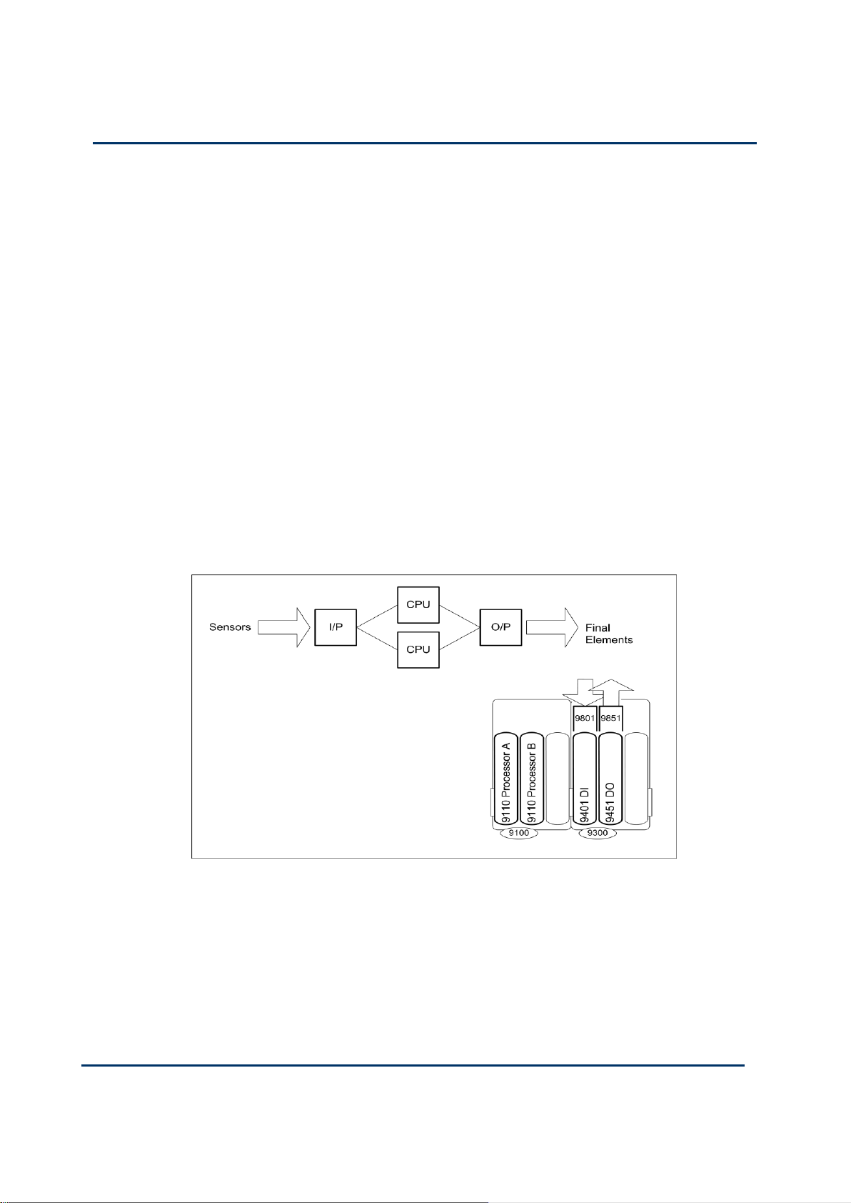
3-4
Document: 553631
(ICSTT-RM447J_EN_P) Issue: 09:
Solutions Handbook (AADvance Controller)
Adding a 2nd Processor for a Higher SIL Rating Configuration
A single processor module is rated SIL2, while two or three in a redundant
arrangement are rated SIL3. Returning to the first example and adding a second
processor module creates a controller suitable for high as well as low demand mode
applications at SIL3.
The T9401/2 digital input module (identical to the module for the SIL2 controller) is
rated SIL3 as it stands. The only constraint is that the simplex output stage will not
drive anenergize to action output for SIL3 - this requires a dual arrangement of output
modules. This output configuration is suitable for a de-energize to action output at
SIL3.
The second processor module provides the increased fault tolerance and gives the
configuration its SIL3 rating. If either processor module should fail, the controller
retains its SIL3 integrity but the module must be replaced within the MTTR.
This controller suits many applications needing a mixture of SIL3 de-energize to action
and SIL2 outputs which do not need the additional fault tolerance offered by dual and
triple modular redundant configurations. The possibilities for expansion are identical to
those for the SIL2 controller.
Page 69

Document: 553631
(ICSTT-RM447J_EN_P) Issue: 09:
3-5
Dual Architecture for Fault Tolerant Applications
Fault Tolerant Input and SIL3 Outputs
A dual architecture configuration shown uses two dual redundant modules for each
stage. The use of two processor modules provides SIL3 integrity for the processor
stage, (as for the previous example), while the addition of the second input module
provides fault tolerance for the inputs.
A SIL3 fault tolerant processor and I/O is achieved by dual input and output module
configurations with dual or triple processor modules. The processor modules operate
in 1oo2D under no fault conditions, degrade to 1oo1D on the detection of the first
fault in either module and fail-safe when there are faults on both modules.
The input modules operate in 1oo2D under non faulted conditions and 1oo1D on
detection of the first fault in either module and will fail-safe when there are faults on
both modules.
The processor will operate in 1oo2D under non-faulted conditions and will degrade to
1oo1D on the first detected fault. For high demand applications the processor must be
repaired within the MTTR or SIL3 safety instrumented functions must be shut down.
For de-energize to action operation one T9451 digital output module is sufficient for
SIL3 requirements. However, for energize to action operation, dual digital output
modules are required.
The single output module operates in 1oo1D under no fault conditions and fail-safe
when there is a fault on the module. For energize to action operation, the output
modules operate in 1oo2D under no fault conditions, degrade to 1oo1D on the
detection of the first fault in either module and fail-safe when there are faults on both
modules.
Page 70

3-6
Document: 553631
(ICSTT-RM447J_EN_P) Issue: 09:
Solutions Handbook (AADvance Controller)
Increasing I/O Capacity
The capacity of this controller is increased by adding pairs of I/O modules and
associated dual termination assemblies. The next example shows how to provide 16
inputs and 16 outputs (this could also be 32 inputs if 16 channel input modules are
used). The outputs shown are digital output modules.
Note: The T9852 dual termination assembly can be used with both 8 channel and 16
channel input modules.
Page 71

Document: 553631
(ICSTT-RM447J_EN_P) Issue: 09:
3-7
Triple Modular Redundant Architecture
A SIL3 TMR architecture offers the highest level of fault tolerance for an AADvance
controller and consists of triple input modules, triple processors and dual output
modules.
The input and processor modules operate in a 2oo3D under no fault conditions,
degrade to 1oo2D on detection of the first fault in any module, and degrade to
1oo1D on the detection of faults in any two modules and will fail-safe when there
are faults on all three modules.
For de-energized to action operation the output modules operate in 2oo2D under
non faulted conditions and degrade to 1oo1D on detection of the first fault in
either module and fail-safe when there are faults on both modules.
For energize to action operation the output modules operate a 1oo2D under no
fault conditions and degrade to 1oo1D on the detection of the first fault in either
module and fail-safe when there are faults on both modules.
In the event of a failure in any element of a channel, the channel processor will still
produce a valid output which could be voted on because of the coupling between the
channels. This is why the triple modular redundant implementation provides a
configuration that is inherently better than a typical 2oo3 voting system.
IMPORTANT: All configurations that use dual or triplicate processor modules are
suitable for SIL3 architectures with de-energize to action outputs. Dual output
modules are required for SIL3 energize to action outputs.
Page 72

3-8
Document: 553631
(ICSTT-RM447J_EN_P) Issue: 09:
Solutions Handbook (AADvance Controller)
You can add further groups of three input modules and pairs of output modules to
provide additional I/O capacity. For example, a triple modular redundant controller
using 8-channel modules for 16 inputs and 16 outputs could be arranged like this. For
16 channel TMR input you should use the T9402 16 channel digital input modules in
the same arrangement.
Using an Expansion Cable
In the example a T9310 expansion cable assembly is used to connect the right-hand
I/O base unit to a further I/O base unit and modules.
Page 73

Document: 553631
(ICSTT-RM447J_EN_P) Issue: 09:
4-1
It is straightforward to implement single, dual and triple I/O architectures for a
In This Chapter
Example Controllers .......................................................................................... 4-1
Mixed I/O Architectures ................................................................................... 4-3
Mixed Safety Integrity Levels ........................................................................... 4-4
Distributed Architectures ................................................................................. 4-5
Typical Network Applications ......................................................................... 4-6
Chapter 4
Mixed Architectures
controller. This can provide a mixed level of redundancy, fault tolerance and safety
integrity level an application needs, without over-specifying some of the I/O or the
need to provide a second controller.
Example Controllers
The following example shows a process protected by one distributed AADvance
system. It uses an 8000 Series Trusted controller to handle bulk I/O, and four
AADvance controllers for other parts of the plant.
Controllers 1 and 2 represent two similar controllers applied to identical, duplicated
areas of plant. The duplication of plant (represented by the two compressors K1 and
K2) in this system allows controllers 1 and 2 to be fail safe designs.
The parts of the plant managed by Controllers 3 and 5 are assumed (for the sake of
this illustration) to need safety instrumented systems certified to a mixture of SIL2 and
SIL3. Controller 3 exploits the flexibility of the AADvance system to provide mixed
SILs within one controller.
Controller 4 manages the fire and gas system throughout the plant. The example uses
an 8000 Series Trusted controller here in a role which uses a large quantity of field
devices. The 8000 Series Trusted controller is completely integrated into the system
and shares the applications with the AADvance controllers.
Page 74

4-2
Document: 553631
(ICSTT-RM447J_EN_P) Issue: 09:
Solutions Handbook (AADvance Controller)
Page 75

Document: 553631
(ICSTT-RM447J_EN_P) Issue: 09:
4-3
Mixed I/O Architectures
An application might readily justify a dual processor and dual I/O for some field
circuits, but not for all. It is easy and economical to configure one controller to
provide a solution. Consider a dual processor system that needs 16 inputs and 16
outputs, half of which must be duplicated and half of which can be simplex. The
requirement would be fulfilled by a controller architecture like this.
Page 76
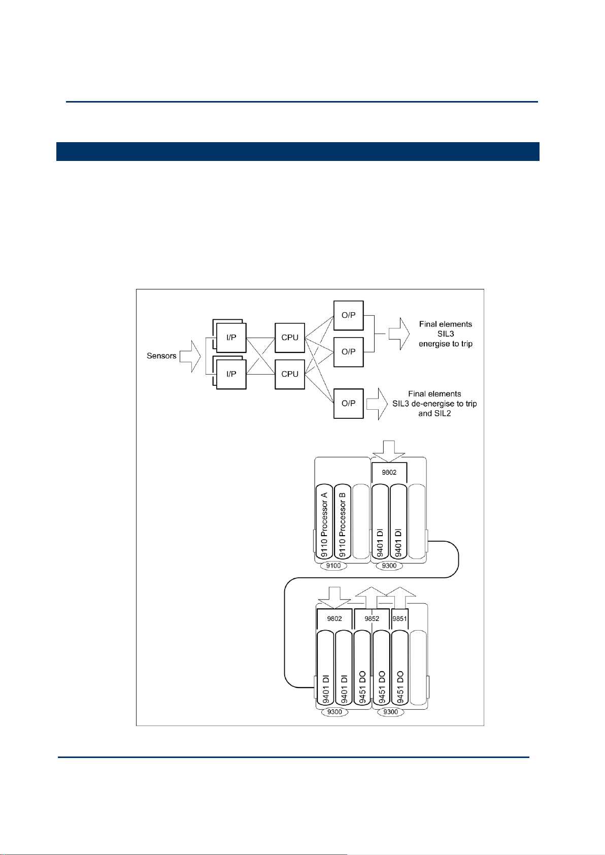
4-4
Document: 553631
(ICSTT-RM447J_EN_P) Issue: 09:
Solutions Handbook (AADvance Controller)
Mixed Safety Integrity Levels
Such is the flexibility of AADvance that a single controller can support mixed safety
integrity levels; for example, if a system needs SIL3 energize to trip outputs alongside
SIL2 outputs.
The following example shows how a small a viable controller for mixed integrity levels
can be when built from AADvance modules. There are 16 inputs (or 32), two
duplicated 8 channel inputs (or duplicated 16 channel versions), and two groups of 8
outputs (one dual, one simplex) for field devices.
Page 77

Document: 553631
(ICSTT-RM447J_EN_P) Issue: 09:
4-5
Distributed Architectures
AADvance is designed to support a distributed safety architecture. Using an SNCP
network a SIL 3 architecture can be maintained across multiple controllers by sharing
safety data over an Ethernet network shown in the example below:
Page 78
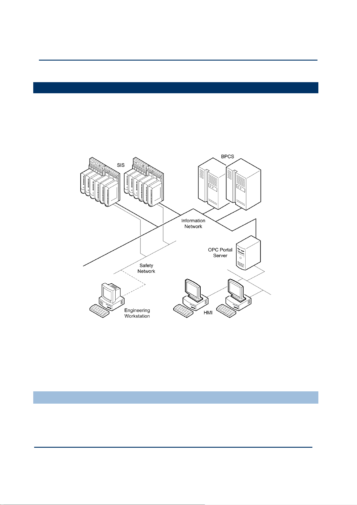
4-6
Document: 553631
(ICSTT-RM447J_EN_P) Issue: 09:
Solutions Handbook (AADvance Controller)
Typical Network Applications
A typical distributed AADvance system uses two networks:
An information network, which provides connectivity to the BPCS (basic process
control system) and to OPC devices
A dedicated safety network, which handles data shared between the AADvance
controllers
The engineering workstation may connect to the safety network (as illustrated), to the
information network or to both networks.
As drawn, the OPC portal server collects data from the controllers and displays it on
the HMIs and, conversely, delivers commands from the HMIs to the controllers. The
information network carries real time data (Modbus TCP) from the BPCS to the
controllers.
Specifying a Safety Network
Once a system uses distributed controllers with shared data, the topology of the safety
network must provide some robustness. To do this, make sure the network has no
single point of failure, and refer to the AAdvance Safety Manual (Document: 553630).
Page 79

Document: 553631
(ICSTT-RM447J_EN_P) Issue: 09:
4-7
Controller Network Connectors
10/100BASE-TX Ports
T9110 Processor Module
E1–1, E1–2
Processor A
E2–1, E2–2
Processor B (if fitted)
E3–1, E3–2
Processor C (if fitted)
The controller features six autosensing 10/100BASE-TX Ethernet ports which allow it
to connect to a local area network through standard RJ45 Ethernet cable. There are
two ports for each processor module.
The controller Ethernet ports are located on the T9110 processor base unit and
identified like this:
Table 16: Allocation of 10/100BASE-TX Ports to Processor Modules
Page 80

4-8
Document: 553631
(ICSTT-RM447J_EN_P) Issue: 09:
Solutions Handbook (AADvance Controller)
This page intentionally left blank
Page 81

Document: 553631
(ICSTT-RM447J_EN_P) Issue: 09:
5-1
The AADvance design concept provides an expandable solution for every application
In This Chapter
I/O Channel Capacity ........................................................................................ 5-1
Adding I/O Channel Capacity .......................................................................... 5-5
Bus Connectors and Expansion Cable ........................................................... 5-5
Redundancy and Fault Tolerance .................................................................... 5-6
Expansion using Distributed Controllers ...................................................... 5-6
Chapter 5
AADvance Scalability
through its current range of I/O modules and termination assemblies. Increased I/O
capacity is possible because of the ease and simplicity for adding new modules and the
flexibility for creating different architectures.
This chapter describes how you can expand the I/O capacity of a controller.
I/O Channel Capacity
The maximum I/O channel capacity of a controller depends on whether you arrange
I/O modules in simplex, dual or triple modular redundant configurations. The total
capacity of an AADvance system remains unlimited, because there are no restrictions
on the number of distributed controllers you can integrate through a network.
By adding new termination assemblies and I/O modules that simply plug together you
can increase the I/O capacity of a controller. You can also use 16 channel modules on
any existing termination assembly and thus increase the I/O channel capacity per
module from 8 channels to 16 channels. The T9310 expansion cable allows you to use
IO Bus 2 and increase the controller capacity by 24 I/O modules giving a total of 48
I/O modules per controller.
An AADvance system offers horizontal scalability with no technical constraints on the
number of distributed controllers within a single system. The system supports and
integrates fully with existing Modbus subsystems and, through its own server, provides
interoperability with HMIs and other OPC devices.
Page 82

5-2
Document: 553631
(ICSTT-RM447J_EN_P) Issue: 09:
Solutions Handbook (AADvance Controller)
Simplex I/O Channel Capacity
When you need I/O modules arranged in only simplex configurations you should use
the simplex termination assembly for each module type. You can use any physical
arrangement of 8-channel and 16-channel input modules with their simplex termination
assemblies, also any arrangement of output modules with simplex termination
assemblies. For example, you might place all digital inputs together in a rack and all
analogue inputs together, or mix them together.
The maximum number of simplex I/O channels is limited only by the choice of
modules. For example, 16 x 16 Channel input modules and 32 x 8 Channel output
modules, equals a maximum of 512 channels
Page 83

Document: 553631
(ICSTT-RM447J_EN_P) Issue: 09:
5-3
Dual I/O Channel Capacity
When you need I/O modules arranged in dual redundant formations, each pair of
modules shares a dual termination assembly and occupies two-thirds of an I/O base
unit. The termination assemblies can bridge adjacent I/O base units, so two base units
will hold three pairs of dual redundant module configurations, while three base units
will hold four pairs. Arrange base units in groups of two or four to optimize capacity
for dual redundant modules.
If you arrange base units in groups of two or four, a single controller supports 24 pairs
of I/O modules. The capacity using for example eight pairs of 16-channel input modules
and sixteen pairs of output modules is 256 I/O channels (8 x 16 = 128, 16 x 8 = 128).
The capacity using 8-channel modules throughout in dual configurations (24 pairs) is 24
× 8 = 192 I/O channels. This might, for example, represent 64 digital inputs, 64
analogue inputs and 64 digital outputs, or any combination of these values with a
granularity of eight, the capacity of one I/O module.
Page 84

5-4
Document: 553631
(ICSTT-RM447J_EN_P) Issue: 09:
Solutions Handbook (AADvance Controller)
Triple Modular Redundant Channel Capacity
When you need input modules arranged in triple modular redundant formations, each
group of three modules will share a single triple termination assembly and occupies a
whole I/O base unit. A single controller supports 16 groups of three modules, so a
hypothetical controller using 16-channel input modules and needing no output channels
would have a capacity of 16 x 16 = 256 input channels.
A solution using 8-channel modules and needing dual output modules as well as
triplicated input modules would, with a ratio of 2:1 of inputs to outputs, provide 96
input channels and 48 output channels. These capacities are derived like this:
Input Channels
12 groups of three 8-channel input modules occupy 12 base units and yield 12 x 8
= 96 input channels.
Output Channels
6 pairs of output modules occupy the remaining 4 base units and yield 6 x 8 = 48
output channels.
Page 85

Document: 553631
(ICSTT-RM447J_EN_P) Issue: 09:
5-5
Adding I/O Channel Capacity
You can specify a new controller to have the precise quantity of I/O channels that you
need and also configure spare I/O channels that you anticipate you may need in the
future. Having done this, it is possible add the hardware to expand the controller.
(Refer to the Technical Feature ―System Modification and Expansion‖)
Bus Connectors and Expansion Cable
The T9100 processor base unit command and response busses and system power for
I/O modules are output by the two connectors on each side of the base unit:
The right-hand connector (designated IO bus 1 in the project tree configuration)
mates with a connector on the T9300 I/O base unit. IO bus 1 supports up to
eight I/O base units and up to 24 I/O modules.
The left-hand connector (designated IO bus 2 in the project tree configuration),
mates with the T9310-02 Backplane Expansion Cable, which will connect it to a
further T9300 I/O base unit. IO Bus 2 supports up to 8 I/O base units and has
response lines for up to 24 I/O modules.
The expansion cable carries module power, command busses and individual response
busses for each I/O module.
Page 86

5-6
Document: 553631
(ICSTT-RM447J_EN_P) Issue: 09:
Solutions Handbook (AADvance Controller)
Redundancy and Fault Tolerance
A significant advantage of the AADvance design is the option to add redundant
modules to increase fault tolerance as an when they are required. Redundant
configurations allow you to replace faulty modules without affecting the system
operation.
This flexibility and operational persistence is made possible by Termination Assemblies
that provide redundant I/O module capacity. By installing a triple termination assembly
you can configure the I/O and use it in a simplex, dual or triple redundant
arrangement.
The AADvance controller therefore provides an economical solution for redundancy
and fault tolerance expansion. You can install the termination assemblies and base units
for additional future capacity, then add the extra I/O modules only when you actually
need them.
Expansion using Distributed Controllers
You can expand any AADvance system by adding extra controllers. The internal
protocols used by the controller do not place limits on the number of controllers you
can have in a system. The AADvance Discover (Discovery and Configuration utility)
enables you to connect to external controllers.
Page 87

Document: 553631
(ICSTT-RM447J_EN_P) Issue: 09:
6-1
This chapter provides a list of key information needed to specify a new AADvance
In This Chapter
Information to Specify a New Controller ..................................................... 6-1
Define a New System ........................................................................................ 6-2
Choosing Termination Assemblies ................................................................. 6-5
Specify I/O Base Units ....................................................................................... 6-5
Estimate AADvance Controller Weight ....................................................... 6-6
Estimate Module Supply Power Dissipation and Field Loop Power
Dissipation ............................................................................................................ 6-7
Chapter 6
Specifying a New Controller
controller. The flowcharts and tables that follow will guide you through the process of
defining a suitable system for your application and requirements.
Information to Specify a New Controller
The following sets of information are needed to specify a new controller:
The intended safety integrity level (SIL2 or SIL3) for your application
The degree of fault tolerance needed
Whether any final elements are energize to action (affects output module
arrangements for SIL3 requirements)
The type and quantity of inputs and outputs
The process safety time for each safety function
All of these items should be assessed and known for the particular plant and the
intended application.
Page 88

6-2
Document: 553631
(ICSTT-RM447J_EN_P) Issue: 09:
Solutions Handbook (AADvance Controller)
Define a New System
The charts use minimal designs to illustrate particular solutions.
Page 89

Document: 553631
(ICSTT-RM447J_EN_P) Issue: 09:
6-3
Page 90

6-4
Document: 553631
(ICSTT-RM447J_EN_P) Issue: 09:
Solutions Handbook (AADvance Controller)
Page 91

Document: 553631
(ICSTT-RM447J_EN_P) Issue: 09:
6-5
Choosing Termination Assemblies
Simplex I/O Module
Configuration
Dual I/O Module
Configuration
Triple I/O Module
Configuration
Digital input
T9801, Digital Input
TA, 16 channel,
Simplex Commoned
(non-isolated)
T9802, Digital Input
TA, 16 channel,
Dual
T9803, Digital Input
TA, 16 channel, Triple
Analogue input
T9831, Analogue Input
TA, 16 channel,
Simplex, commoned
(non-isolated)
T9832, Analogue
Input TA, 16
channel, Dual
T9833, Analogue Input
TA, 16 channel, Triple
Digital output
T9851, Digital Output
TA, 8 channel, Simplex,
commoned
(non-isolated)
T9852, Digital
Output TA, 8
channel, Dual
(non-isolated)
Not applicable
Analogue Output
T9881, Analogue
Output TA, 8 Channel,
Simplex, commoned
T9882, Analogue
Output TA, 8
channel, Dual
Not applicable
The use of termination assemblies gives the AADvance system exceptional flexibility
for creating different architectures and expanding the system. Each termination
assembly is a very simple circuit that is matched to a type of I/O module and to a
particular module configuration. This table shows a summary of the termination
assemblies which are available and the associated I/O module configurations.
Table 17: Choosing a Termination Assembly
IMPORTANT: The termination assemblies for inputs accommodate 8-channel I/O
modules and 16-channel I/O modules. A dual or triple arrangement can be made of 8or 16-channel modules, but not a mixture of the two.
Specify I/O Base Units
You need one termination assembly for each group of associated modules. For
example:
Four T9401 digital input modules used in two, dual redundant configurations need
two T9802 termination assemblies — one for each pair of modules
Four T9401 digital input modules used for simplex inputs need four T9801
termination assemblies — one for each module
The T9300 I/O base unit (3 way) is a single, standardized design which suits all
termination assemblies and I/O modules. The base unit can accommodate one triple
modular redundant assembly, one dual assembly and one simplex assembly or up to
three to simplex assemblies. The dual and triple modular redundant assemblies can
bridge adjacent base units, so two base units can (for example) hold three dual
assemblies.
Page 92

6-6
Document: 553631
(ICSTT-RM447J_EN_P) Issue: 09:
Solutions Handbook (AADvance Controller)
Estimate AADvance Controller Weight
Item
Number
Used
Weight Allowance
g (oz.)
Subtotal
T9100 Processor Base Unit
× 460g (16 oz.)
T9110 Processor Module
× 430g (15oz)
T9401 Digital input module, 24V dc, 8 channel
× 280g (10oz)
T9402 Digital input module, 24V dc, 16 channel
× 340g (12oz)
T9431 Analogue input module, 8 channel
× 280g (10oz)
T9432 Analogue input module, 16 channel
× 340g (12oz)
T9451 Digital output module, 24V dc, 8 channel
× 340g (12oz)
T9482 Analogue output module, 8 channel
× 290g (10.5oz)
T9300 I/O base unit (3 way)
× 133g (5 oz.)
T98x1 Simplex Termination assembly
× 133g (5 oz.)
T98x2 Dual Termination Assembly
× 260g (10oz)
T98x3 Triple Termination Assembly
× 360g (13oz)
T9310 Expansion cable assembly and 2m cable
× 670g (24 oz.)
T9841 Termination Assemblies (average weight)
× 175g (6 oz.)
Total estimated controller weight
Use the following table to estimate the weight of your system.
Table 18: AADvance Controller Module Weight
Page 93

Document: 553631
(ICSTT-RM447J_EN_P) Issue: 09:
6-7
Item
Number
of
Modules
Power Dissipation
Subtotal
(W/BTU/hr)
T9110 Processor Module
× 8.0W (27.3BTU/hr)
=
T9401 Digital Input Module 24V dc, 8 channel
× 3.3W (11.3BTU/hr)
=
T9402 Digital Input Module 24V dc, 16 channel
× 4.0W (13.6BTU/hr)
=
T9431 Analogue Input Module, 8 channel
× 3.3W (11.3BTU/hr)
=
T9432 Analogue Input Module, 16 channel
× 4.0W (13.6BTU/hr)
=
T9451 Digital Output Module, 24V dc, 8 channel
× 3.0W (10.2BTU/h)
=
T9482 Analogue Output Module, 8 channel, isolated
× 3.6W (12.3BTU/hr)
=
Total:
Item
Number
of Field
loops
Maximum Field
Loop Power
Dissipation
Subtotal
(W/BTU/hr)
T9801/2/3 Digital Input Termination Assembly (powered by
the T9401/2 module)
× 0.2W (0.68BTU/hr)
=
T9831/2/3 Analogue Input Termination Assembly (powered
by the T9431/2 module)
× 0.08W
(0.27BTU/hr)
=
T9451 Digital Output Module, 24V dc, 8 channel (1A load)
x 0.57W (1.94
BTU/hr)
=
T9482 Analogue Output Module, 8 channel, isolated
× 0.77W
(2.63BTU/hr)
=
Total:
Estimate Module Supply Power Dissipation and Field Loop Power Dissipation
Module supply voltage and field power consumption is dissipated as heat. Use these
tables to estimate the supply voltage and field power heat dissipation of your system.
Note: All figures given are worst-case estimates based upon maximum operating field
current and voltages.
Table 19: Estimating Module Supply Power Dissipation
Table 20: Estimating Field Loop Power Dissipation
Page 94

6-8
Document: 553631
(ICSTT-RM447J_EN_P) Issue: 09:
Solutions Handbook (AADvance Controller)
This page intentionally left blank
Page 95

Document: 553631
(ICSTT-RM447J_EN_P) Issue: 09:
7-1
This chapter provides a brief technical overview and technical specification of each
In This Chapter
T9110 Processor Module ................................................................................. 7-2
T9100 Processor Base Unit ............................................................................. 7-5
T9300 I/O Base Unit (3 way) ........................................................................... 7-8
T9310 Expansion Cable Assembly ................................................................ 7-10
T9401/2 Digital Input Module, 24V dc, 8/16 channel ............................... 7-12
T9801/2/3 Termination Assemblies for Digital Inputs ............................. 7-14
T9431/2 Analogue Input Module, 8/16 Channel ....................................... 7-16
T9831/2/3 Termination Assemblies for Analogue Inputs ....................... 7-18
T9451 Digital Output Module, 24V dc, 8 channel .................................... 7-20
T9851/2 Termination Assemblies for Digital Outputs ............................ 7-22
T9481/2 Analogue Output Module .............................................................. 7-24
T9881/2 Termination Assembly for Analogue Output Module ............ 7-26
Chapter 7
Module Overview and Specifications
module and its associated termination assembly. Each module has a set of front panel
LEDs to provide status and failure indications. Also, variables included with the
application software can be set up to also monitor and report on the system and
module status.
Page 96
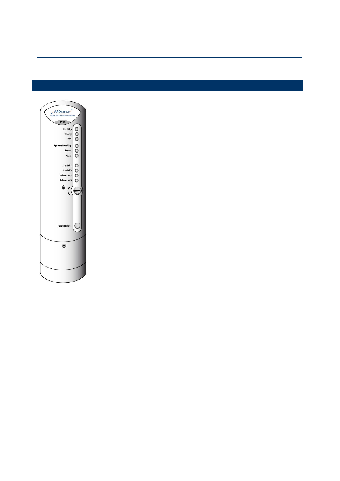
7-2
Document: 553631
(ICSTT-RM447J_EN_P) Issue: 09:
Solutions Handbook (AADvance Controller)
T9110 Processor Module
The T9110 processor module is the central processing unit of an
AADvance controller. The processor module carries out the
following critical process and safety controller tasks:
Execution of the AADvance Safety Kernel to solve
application logic
Interfacing with the controller I/O modules, reading and
processing input data and writing output data
Communication with other processor modules, both locally
and across the control network
Initiation of periodic diagnostics for the controller
Communication with other systems such as HMIs
Message encapsulation and verification for secure channel
communication to other nodes
The processor module is galvanically isolated from external
power supplies and data links so that any faults developed in the
field cannot cause the module to fail. The module will continue
to operate in the event of failure of one of its dual redundant
24V dc power supplies. The module incorporates under- and
over-voltage protection for its internal power supplies, which
provide a 'power valid' signal to the modules own diagnostics
microprocessor.
A processor module has two functionally independent,
electrically isolated Ethernet ports. Each port is separately
configurable for multiple protocols such as Modbus RTU, Open
Modbus/TCP and proprietary AADvance protocols, and its data
is available to every processor in the controller.
In addition to the front panel LEDs a Fault Reset button is
provided for the user to reset any fault indications on an I/O
module before the controller is restarted.
Two serial communications ports per processor are provided for Modbus RTU slave
communications. These ports are also functionally and electrically isolated from each
other. They support RS-485 (4– and 2–wire) communications and can be configured to
support asynchronous data rates from 1,200 to 115,200 baud.
The processor periodically initiates internal diagnostic tests which, together with a
watchdog circuit, monitor the processor internal performance. If the tests detect a
serious fault, the processor module will shut down. A controller can use one, two or
three processor modules. Using two or three processor modules provides a fault
tolerant processor architecture.
Page 97

Document: 553631
(ICSTT-RM447J_EN_P) Issue: 09:
7-3
If a controller uses two or three processor modules, and one processor module
develops a fault, plant maintenance personnel can fit a new processor module while the
controller is on-line. The new processor module automatically carries out selfeducation and synchronizes with the other processors. Fault detection and fail-over in
redundant processor configurations is automatic and has no impact on controller
operation.
Page 98

7-4
Document: 553631
(ICSTT-RM447J_EN_P) Issue: 09:
Solutions Handbook (AADvance Controller)
Processor Module Specification
Attribute
Value
Functional Characteristics
Degradation
1oo1D, 1oo2D and 2oo3D
Processor clock
400MHz
Memory
Boot flash
512kB
SRAM
512kB
Bulk flash
64MB
SDRAM
32MB
Sequence of events
(for internal variables)
Event resolution
1ms
Time-stamp accuracy
Application Scan
Performance Characteristics
Safety Integrity Level (SIL)
1 processor: non-safety applications up to SIL1
and SIL2 safety applications
2 Processors: up to SIL3 safety applications
3 Processors: up to SIL3 fault tolerant and
TMR safety applications.
I/O Modules supported
48
Electrical Characteristics
Module supply voltage:
Voltage
Redundant + 24V dc nominal; 18V dc to 32V
dc range
Module supply power dissipation
8W (27.3 BTu/h)
Typical Surface Temperature of an
Operating Module
43°C ± 5°C
Mechanical Specification
Dimensions (height × width × depth)
166mm × 42mm × 118mm
(6-½ in. × 1-5/8 in. × 4-5/8 in.)
Weight
430g (15 oz.)
Casing
Plastic, non-flammable
Table 21: Processor Module Specification
Page 99
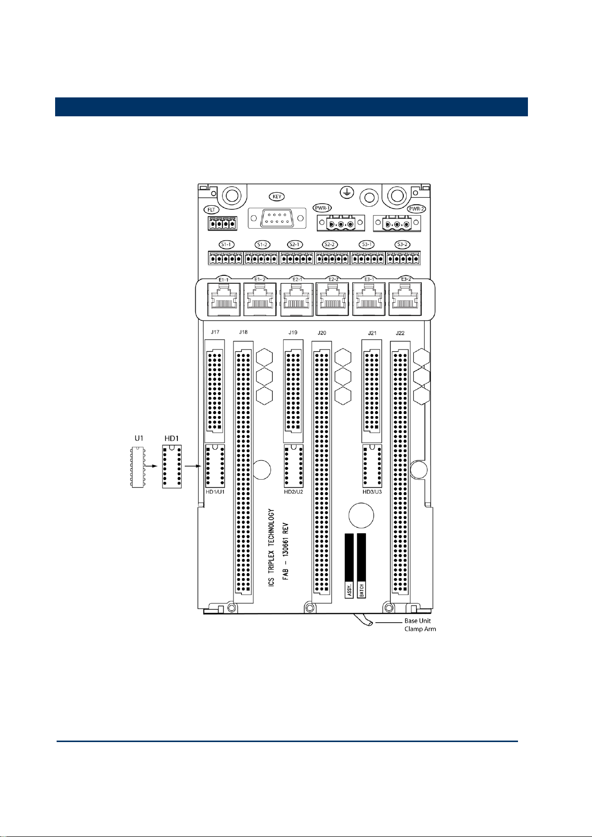
Document: 553631
(ICSTT-RM447J_EN_P) Issue: 09:
7-5
T9100 Processor Base Unit
Every AADvance controller has one T9100 processor base unit. A processor base unit
supports one, two or three modules depending on the architecture chosen for the
application.
Page 100

7-6
Document: 553631
(ICSTT-RM447J_EN_P) Issue: 09:
Solutions Handbook (AADvance Controller)
The processor base unit provides the electrical connections between the T9110
processor modules, and the rest of the controller modules and has the following
connections:
Command and response bus connections for up to 48 I/O modules
Inter-processor links
Two Ethernet 100 BaseT connectors per processor
Two serial data connections per processor
Dual +24v System power
Ground stud
Program enable key
The processor base unit holds the IP address of each processor module separately in a
BUSP (U1 shown in above illustration) which is installed during manufacture. This
means that you can remove a defective processor module and install a new one
without needing to set up the IP address of the new module.
 Loading...