

Page 1

AADvance
The Next Step in Automation
AADvance Controller
Configuration Guide
Issue: 07
DOCUMENT: 553633
ICSTT-RM405F-EN-P
Page 2

ii
Document: 553633
ICSTT-RM405f-EN-P
Issue: 07
Configuration Guide (AADvance Controller)
This page intentionally left blank
Page 3

Document: 553633
ICSTT-RM405f-EN-P
Issue :07
iii
Notice
In no event will Rockwell Automation be responsible or liable for indirect or
consequential damages resulting from the use or application of this equipment. The
examples given in this manual are included solely for illustrative purposes. Because of
the many variables and requirements associated with any particular installation,
Rockwell Automation does not assume responsibility or reliability for actual use based
on the examples and diagrams.
No patent liability is assumed by Rockwell Automation, with respect to use of
information, circuits, equipment, or software described in this manual.
Reproduction of this manual in whole or in part, without written permission of
Rockwell Automation is prohibited.
All trademarks are acknowledged.
Disclaimer
It is not intended that the information in this publication covers every possible detail
about the construction, operation, or maintenance of a control system installation. You
should refer to your own (or supplied) system safety manual, installation instructions
and operator/maintenance manuals.
Revision and Updating Policy
This document is based on information available at the time of its publication; however,
the document contents are subject to change from time to time. You should contact
Rockwell Automation Technical Support by e-mail — icstsupport@ra.rockwell.com to
check if you have the latest version of this publication.
© Copyright Notice, Rockwell Automation 2012
This document contains proprietary information that is protected by copyright. All
rights are reserved.
Documentation Feedback
Your comments will help us to serve your documentation needs better. If you
discover any errors or have any suggestions on how to improve this publication send
your comments to our product support group: icstsupport@ra.rockwell.com
This Configuration Guide applies to Release 1.3.
Page 4

iv
Document: 553633
ICSTT-RM405f-EN-P
Issue: 07
Configuration Guide (AADvance Controller)
Issue Record
Issue
Date
Comments
01
Jan 2009
First Issue
01A
Aug 2009
Release 1.1 Issue
01B
Aug 2009
Updated issue for per review comments
02
Nov 2009
Release 1.1.1
03
July 2010
Update for CRs
04*
Oct 2011
Release 1.2
05
Apr 2012
Updated Release 1.2 version with Analogue Output Module
information added.
06
June 2012
Release 1.3 & 1.3.1
07
June 2013
Update to Add information to on-line update topics
was originally designated Issue: Release 1.2
Page 5
Document: 553633
ICSTT-RM405f-EN-P
Issue :07
v
Notes and Symbols used in this manual
This symbol calls attention to items which "must" be considered and implemented
when designing and building an AADvance controller for use in a Safety
Instrumented Function (SIF). It appears extensively in the AADvance Safety Manual.
WARNING
ELECTRICAL ARCS AND EXPLOSION RISK IN HAZARDOUS
AREAS
If you connect or disconnect wiring, modules or communications cabling while
power is applied, an electrical arc can occur. This could cause an explosion in
hazardous location installations. Do not remove wiring, fuses, modules or
communications cabling while circuit is energized unless area is known to be
non hazardous.
Failure to follow these instructions may result in personal injury.
WARNING
MAINTENANCE
Maintenance must be carried out by people who are experienced in working on
electronic equipment and in particular safety related systems.They should have
knowledge and experience of local operating and safety standards. Failure to
follow these recommendations may result in situations that can lead system
damage and even personal injury.
CAUTION
RADIO FREQUENCY INTERFERENCE
Most electronic equipment is influenced by Radio Frequency Interference.
Caution should be exercised with regard to the use of portable communications
equipment around such equipment. Signs should be posted in the vicinity of the
equipment cautioning against the use of portable communications equipment.
CAUTION
HEAT DISSIPATION AND ENCLOSURE POSITION
System and field power consumption by modules and termination assemblies is
dissipated as heat. You should consider this heat dissipation on the design and
positioning of your enclosure; e.g. enclosures exposed to continuous sunlight
will have a higher internal temperature that could affect the operating
temperature of the modules. Modules operating at the extremes of the
temperature band for a continuous period can have a reduced reliability.
Note: Notes are used extensively to provide important information about the
product.
Standard Warnings and Cautions
Page 6

vi
Document: 553633
ICSTT-RM405f-EN-P
Issue: 07
Configuration Guide (AADvance Controller)
Forward
This manual defines how to configure an AADvance controller using the AADvance
Workbench to meet your SIF application requirements.
Who Should Use This Manual
This manual is intended primarily for System Integrators. The information contained in
this manual is aimed at engineers experienced in building and setting up safety-related
systems. It is expected that the users have been trained and have a thorough
understanding of the intended application.
Note: System Integrators are responsible for compliance to local, national and
international standards that apply for the application that AADvance is being used for.
System Integrators are responsible for resolving any conflicts between this document
and the applicable project codes and standards.
If AADvance is being used for any Safety Functions the System Integrators are
responsible for applying the requirements defined in the AADvance Safety Manual.
Page 7

Page 8

viii
Document: 553633
ICSTT-RM405f-EN-P
Issue 07:
Configuration Guide (AADvance Controller)
Contents
Chapter 1 Introduction ............................................................................................. 1-1
Purpose and Scope ............................................................................................................................................ 1-1
AADvance Workbench and Software Development Environment ....................................................... 1-1
About The Configuration Process ................................................................................................................. 1-3
Integrating the AADvance Controller with Other Systems .................................................................... 1-4
Application Scan Model .................................................................................................................................... 1-5
Scan Times ..................................................................................................................................................... 1-6
Chapter 2 Software Installation ............................................................................... 2-1
AADvance WorkbenchLicensing Options ................................................................................................... 2-1
Install the AADvance Workbench and Utilities ......................................................................................... 2-1
Add and Activate a New AADvance Workbench License ...................................................................... 2-5
Updating or Upgrading an Existing License ................................................................................................. 2-7
Update or Upgrade a Hardware/Software License Key ..................................................................... 2-7
Using a Floating License Server ................................................................................................................ 2-8
Set Up a Server for Hardware Floating Licenses ................................................................................. 2-9
Set Access to Floating Licenses .............................................................................................................. 2-10
Chapter 3 Connecting the Workbench to the Controller .................................... 3-1
Setting Up the Controller IP Address for AADvance Workbench Communications ...................... 3-1
Controller IP Address Setting ................................................................................................................... 3-1
AADvanceDiscover Utility ........................................................................................................................ 3-1
About Discover Communications ................................................................................................................. 3-2
Discover Communications Fault-Finding ..................................................................................................... 3-3
Configure the Controller Resource Number ............................................................................................. 3-3
Configure the IP Address in the Controller ............................................................................................... 3-5
Save and Load a Configuration ................................................................................................................. 3-7
Chapter 4 Configuring the Processor Modules ....................................................... 4-1
View Module Firmware Versions ................................................................................................................... 4-1
ControlFLASH Firmware Upgrades .............................................................................................................. 4-5
Stage 1: Installing the ControlFLASH Firmware ................................................................................... 4-6
Upgrade the Processor Module Recovery Mode Firmware .............................................................. 4-9
Stage 2: Installing the ControlFLASH Firmware Kit for OS, FPGA, LSP and BUSP .................. 4-14
Upgrade Processor OS, FPGAFPGA, LSP and BUSP Firmware ..................................................... 4-15
Configure Controller Type (Standard or Eurocard) ............................................................................... 4-19
Configure the Top-level Process Safety Time (PST) ............................................................................... 4-20
Configure the Processor Battery Alarm .................................................................................................... 4-21
Configure the Serial Ports ............................................................................................................................. 4-22
Serial Port Protocols ................................................................................................................................. 4-23
Page 9

Document: 553633
ICSTT-RM405f-EN-P
Issue 07:
ix
Serial Port Parameters .............................................................................................................................. 4-23
Time Synchronization (SNTP) ...................................................................................................................... 4-24
Configure the Controller as an SNTP Client ...................................................................................... 4-24
Configure the Controller as an SNTP Server ..................................................................................... 4-25
Using the Controller as a Modbus Slave .................................................................................................... 4-27
Support for Modbus Slave Exceptions .................................................................................................. 4-27
Configure the Controller Modbus Slaves ............................................................................................ 4-28
Modbus Slave Communication Parameters ......................................................................................... 4-29
Transparent Communication Interface (TCI) ........................................................................................... 4-30
TCI Configuration ...................................................................................................................................... 4-30
DiffServ Configuration .................................................................................................................................... 4-32
Configure DiffServ ..................................................................................................................................... 4-32
Ethernet Forwarding ....................................................................................................................................... 4-34
Configure Ethernet Forwarding ............................................................................................................. 4-34
About T9110 Processor Variables ............................................................................................................... 4-36
Wire Processor Variables ........................................................................................................................ 4-36
Unwire Processor Variables .................................................................................................................... 4-37
Status Integers ............................................................................................................................................ 4-38
Control Integers ......................................................................................................................................... 4-40
Status Booleans .......................................................................................................................................... 4-40
Control Booleans ....................................................................................................................................... 4-47
RTC Status Variables ................................................................................................................................ 4-48
RTC Program Variables ............................................................................................................................ 4-50
RTC Control Variables ............................................................................................................................. 4-53
Set the Processor Clock ................................................................................................................................ 4-57
Chapter 5 Configuring the Controller I/O .............................................................. 5-1
About Configuring I/O Modules ..................................................................................................................... 5-1
Defining the I/O Hardware Architecture ............................................................................................... 5-2
Example Controller Configuration .......................................................................................................... 5-3
Assign I/O Modules to I/O Bus Slots....................................................................................................... 5-4
Enable or Disable the On-line Update Feature .................................................................................... 5-8
Perform an On-line Update ....................................................................................................................... 5-9
Configure the I/O Module Process Safety Time ................................................................................. 5-12
Wire Status Variables to I/O Modules .................................................................................................. 5-12
T9K_TA_GROUP_STATUS (I/O Module Status Information) ...................................................... 5-14
About Configuring I/O Channels ................................................................................................................. 5-16
Wire Variables to Digital Input Channels ............................................................................................ 5-16
Wire Variables to Analogue Input Channels ....................................................................................... 5-17
Wire Variables to Digital Output Channels ........................................................................................ 5-18
Wire Variables to Analogue Output Channels ................................................................................... 5-19
Configuring Digital Inputs .............................................................................................................................. 5-19
T9K_DI_COMPACT and T9K_DI_FULL (Digital Inputs) ............................................................... 5-20
Faulted State for Digital Inputs ............................................................................................................... 5-21
Threshold Values for Digital Inputs ....................................................................................................... 5-22
Page 10

x
Document: 553633
ICSTT-RM405f-EN-P
Issue 07:
Configuration Guide (AADvance Controller)
Configuring Analogue Inputs ......................................................................................................................... 5-26
T9K_AI_COMPACT and T9K_AI_FULL (Analogue Inputs) .......................................................... 5-26
Faulted State for Analogue Inputs .......................................................................................................... 5-27
HART ............................................................................................................................................................ 5-28
About Threshold Values for Analogue Inputs ..................................................................................... 5-38
Configuring Digital Outputs .......................................................................................................................... 5-41
T9K_DO_COMPACT and T9K_DO_FULL (Digital Outputs) ..................................................... 5-41
The State Variable for Digital Outputs ................................................................................................. 5-43
Overcurrent Protection for Digital Outputs ...................................................................................... 5-44
Faulted State for Digital Outputs ........................................................................................................... 5-45
Configure Advanced Channel Settings for Digital Outputs ............................................................. 5-45
Status Variables for Digital Output Modules............................................................................................. 5-47
Wire Status Variables to a Digital Output Module............................................................................ 5-47
Unwire Status Variables from a Digital Output Module................................................................... 5-48
Status Booleans .......................................................................................................................................... 5-48
Field Power Status Integers ..................................................................................................................... 5-49
Configuring Analogue Outputs ..................................................................................................................... 5-51
The State Variable for Analogue Outputs ............................................................................................ 5-51
T9K_AO_COMPACT and T9K_AO_FULL (Analogue Outputs)................................................. 5-52
Faulted State for Analogue Outputs ...................................................................................................... 5-53
Configure Advanced Channel Settings for Analogue Output Channels ....................................... 5-53
Chapter 6 Setting Up ................................................................................................ 6-1
Create a New Project ...................................................................................................................................... 6-1
Compiler Verification Tool ............................................................................................................................. 6-2
Enable the Compiler Verification Tool (CVT) ...................................................................................... 6-2
Allocate IP Addresses for Network Communications ............................................................................. 6-4
Configure the IP Address of the Target Controller .................................................................................. 6-5
Chapter 7 Using the Dictionary ............................................................................... 7-1
About the Dictionary ........................................................................................................................................ 7-1
Properties for AADvance Variables .............................................................................................................. 7-1
Create or Modify Variables in the Dictionary ............................................................................................ 7-4
Edit the Contents of a Cell in the Dictionary ....................................................................................... 7-4
Edit the Contents of a Row in the Dictionary ...................................................................................... 7-6
SOE Service Parameters ............................................................................................................................. 7-7
Chapter 8 Using CIP over EtherNet/IP ................................................................... 8-1
CIP over EtherNet/IP ........................................................................................................................................ 8-1
Define a CIP Network ...................................................................................................................................... 8-2
Data Types for CIP over Ethernet/IP ............................................................................................................ 8-4
Using the Dictionary with CIP ........................................................................................................................ 8-4
CIP in the Dictionary View ........................................................................................................................ 8-4
Parameters for CIP Producer and Consumer Varaibles .................................................................... 8-5
Configure an AADvance Variable as a Producer ....................................................................................... 8-6
Page 11

Document: 553633
ICSTT-RM405f-EN-P
Issue 07:
xi
Defining The AADvance Controller as a CIP Producer .......................................................................... 8-6
Configure an AADvance Variable as a Consumer ..................................................................................... 8-8
Obtaining the Connection Status for a Consumed Variable ................................................................. 8-10
CIP within the Application Scan Cycle ....................................................................................................... 8-11
About the RSLogix 5000 Configuration ..................................................................................................... 8-11
Rules for Counting Connections ................................................................................................................. 8-11
Set the RSLogix UNICAST Configuration ................................................................................................. 8-14
Further Information on CIP over Ethernet/IP .......................................................................................... 8-15
Chapter 9 Configuring Modbus Master ................................................................... 9-1
Modbus Master ................................................................................................................................................... 9-2
Modbus Standards ............................................................................................................................................. 9-2
Modbus Master Hardware and Physical Connections .............................................................................. 9-2
Modbus Master Command Set ....................................................................................................................... 9-4
Modbus Data Types and Addressing ............................................................................................................. 9-4
Modbus Message Scheduling ........................................................................................................................... 9-5
Handling Modbus Communication Errors ............................................................................................. 9-7
Modbus Statistics ............................................................................................................................................... 9-7
Modbus Service Parameters ............................................................................................................................ 9-8
Diagnosing Modbus Communications and Slave Devices ........................................................................ 9-8
Modbus Exception Responses ........................................................................................................................ 9-9
AADvance Objects for Modbus Master ....................................................................................................... 9-9
Modbus Master Capacities .............................................................................................................................. 9-9
Planning for Modbus Master .......................................................................................................................... 9-10
Physical Connections for Modbus RTU ..................................................................................................... 9-10
Connect a Slave Device, Full Duplex .................................................................................................... 9-11
Connect Multiple Slave Devices, Full Duplex...................................................................................... 9-12
Connect a Slave Device, Half Duplex ................................................................................................... 9-13
Connect Multiple Slave Devices, Half Duplex..................................................................................... 9-14
Configure the Serial Ports for Modbus Master ........................................................................................ 9-15
Serial Port Parameters .............................................................................................................................. 9-16
Physical Connections for Modbus TCP ...................................................................................................... 9-16
Setting up the Project for Modbus Master Operation ............................................................................ 9-16
About the Modbus Master Bus ............................................................................................................... 9-17
Insert the Modbus Master Bus ................................................................................................................ 9-17
Create a Modbus Master Object ................................................................................................................. 9-18
Modbus Master Communication and Control Settings .................................................................... 9-19
Configure a Modbus Master Object for Modbus RTU ..................................................................... 9-21
Configure a Modbus Master Object for Modbus TCP ..................................................................... 9-22
Controlling a Modbus Master Object ......................................................................................................... 9-25
Modbus Ping Mode, Interval and Address............................................................................................ 9-26
Configure Statistics for a Modbus Master Object ................................................................................... 9-32
Modbus Statistics Parameters ................................................................................................................. 9-32
Page 12

xii
Document: 553633
ICSTT-RM405f-EN-P
Issue 07:
Configuration Guide (AADvance Controller)
Create Links to Modbus Slaves .................................................................................................................... 9-33
Modbus Slave Link Identification and Control Settings .................................................................... 9-34
Configure a Modbus Slave Link for Modbus RTU.............................................................................. 9-36
Configure a Modbus Slave Link for Modbus TCP .............................................................................. 9-37
Choosing Names for Modbus Objects ................................................................................................. 9-38
Modbus Slave ID......................................................................................................................................... 9-38
Modbus Slave Wait Interval ..................................................................................................................... 9-38
Modbus Ping Mode, Interval and Address............................................................................................ 9-38
Modbus Slave Commands .............................................................................................................................. 9-39
Serial Port .................................................................................................................................................... 9-39
Ethernet and Serial Port ........................................................................................................................... 9-39
Modbus Slave Link Control and Status Registers..................................................................................... 9-41
Modbus Slave Link Control Register ..................................................................................................... 9-41
Modbus Slave Link Status Register ........................................................................................................ 9-42
Add Messages for a Modbus Slave ............................................................................................................... 9-43
Modbus Slave Link Message Parameters .............................................................................................. 9-45
Controlling a Modbus Message ............................................................................................................... 9-46
Configure Statistics for a Modbus Slave Link ............................................................................................ 9-46
Modbus Statistics Parameters ................................................................................................................. 9-47
Remove a Slave Link ........................................................................................................................................ 9-47
Remove all Slave Links .................................................................................................................................... 9-48
Remove a Modbus Master Object ............................................................................................................... 9-48
Chapter 10 SNCP and Variable Bindings ................................................................ 10-1
SNCP Safety Networks .................................................................................................................................. 10-1
SNCP Networks ........................................................................................................................................ 10-2
Set Up Multiple SNCP Networks .......................................................................................................... 10-5
SNCP KVB Driver Timeout Values ....................................................................................................... 10-7
Configure Bindings ................................................................................................................................... 10-10
SNCP Binding Error Variables .............................................................................................................. 10-13
Chapter 11 Peer-to-Peer Network .......................................................................... 11-1
Peer to Peer Features ..................................................................................................................................... 11-1
Peer to Peer Configuration Process ........................................................................................................... 11-2
Create a Peer to Peer Network .................................................................................................................. 11-2
Peer-to-Peer Subnet Controller Configuration ....................................................................................... 11-3
Set up the Peer IP Addresses and Status Variable ............................................................................. 11-6
Peer to Peer Data Boards.............................................................................................................................. 11-6
Configure Input Boards .................................................................................................................................. 11-7
Configure Analogue Input Boards ............................................................................................................... 11-7
Configure Digital Input Boards ................................................................................................................... 11-10
Wire Digital Input Board Status Variables ......................................................................................... 11-11
Wire Digital Input Channel Data Variables ....................................................................................... 11-12
Configure Output Boards ............................................................................................................................ 11-13
Page 13

Document: 553633
ICSTT-RM405f-EN-P
Issue 07:
xiii
Configure Analogue Output Boards ......................................................................................................... 11-14
Configure Digital Output Board................................................................................................................. 11-16
Peer to Peer Configuration Example 1 ..................................................................................................... 11-18
Peer-to-Peer Controller Setting Summary ........................................................................................ 11-19
Peer to Peer Data Summary ................................................................................................................. 11-24
Chapter 12 Glossary of Terms ................................................................................. 12-1
Chapter 13 Additional Resources ............................................................................ 13-1
Regional Offices ................................................................................................................................................ 13-2
Page 14

Page 15

Document: 553633
ICSTT-RM405f-EN-P
Issue 07
1-1
This chapter provides a brief overview of the AADvance Workbench and this manual.
In This Chapter
Purpose and Scope ............................................................................................. 1-1
AADvance Workbench and Software Development Environment ........ 1-1
About The Configuration Process .................................................................. 1-3
Integrating the AADvance Controller with Other Systems ..................... 1-4
Application Scan Model ..................................................................................... 1-5
Chapter 1
Introduction
Purpose and Scope
This technical manual defines the process you should follow to configure a new system
or re-configure an existing system. It includes background information and detailed
procedures for the following:
Setting the controller IP Address
Defining the processor configuration
Defining the variables in the Dictionary
Configuring the I/O modules and channels
setting up Modbus and CIP
The step-by-step instructions are based on using the AADvance Workbench
configuration tools.
Also included is reference information about module status parameters and I/O
variables to help you decide which variable types to use, and included is a brief
description of the data values provided by the I/O modules.
The instructions for installing the Workbench, choosing a licensing option and
connecting the application to the controller are also covered by this manual.
AADvance Workbench and Software Development Environment
The 9110 Processor Module runs the Workbench, it must have the following
specification:
Operating Systems:
Windows XP with Service Pack 3
Windows Vista, Windows 7 & Server 2003 in both 32-bit and 64-bit versions
Note: Network Licensing - Windows 64-bit version will only work with the USB
licsensing method.
Page 16

1-2
Document: 553633
ICSTT-RM405f-EN-P
Issue 07
Configuration Guide (AADvance Controller)
CAUTION: Do not use XP Professional x64 edition
Network port (10/100 Base T Ethernet)
Access to a CD-ROM drive, for software installation
If the application adopts the dongle licensing option for the software, the processor
module will also require one free USB port.
The AADvance workstation uses software that enables you to design the complete
control strategy as one, then to target parts of the strategy at each controller.
Interaction between the resources is automatic, significantly reducing the complexity of
configuration in a multi-resource solution.
The workstation software, known as the Workbench is compliant with IEC61131
industrial standard and has the following powerful features:
the regulation of the flow of control decisions for an interacting distributed control
system
providing for the consistency of data
providing a means for synchronous operation between devices
eliminating the need to have separate synchronous schemes
easing the development and maintenance of robust systems
The Workbench is a complete software development environment for a controller.
It lets you create local and distributed control applications using the five languages of
IEC 61131-3. Engineers can choose one language or a combination of languages that
best suits their knowledge and programming style and the nature of the application.
It is a secure development environment that requires a hardware or software license
to run on a PC. There is also a Program Enable key (not applicable to a Euro
Controller) that must be plugged into the processor base unit to allow the user to
modify and download the application resource or access the AADvance Discovery tool
to set or change the controller IP address. The Program Enable key when it is
removed protects the application from unauthorized access.
The development environment includes:
tools for program development
program documentation
function block library management
application archiving
database configuration
import/export utilities
on-line monitoring
off-line simulation and controlled on-line changes.
Page 17

Document: 553633
ICSTT-RM405f-EN-P
Issue 07
1-3
Programs can be simulated and tested and tested on the computer before downloading
CAUTION
WORKBENCH FOR USE IN SAFETY APPLICATIONS
If the Workbench is used for safety related applications then you must follow
the safety application guidelines contained in the AADvance Safety Manual (Doc
No: 553630).
to the controller hardware. Also provided is a set of configuration tools that enables
you to define the hardware architecture in the software; set up the processor
functionality; and connect application variables to the Workbench application
resource program that will monitor processor and I/O module status information and
report I/O channel data values to the Workbench. Resource Control applications can
be distributed across several hardware platforms, communicating with each other
through secure networks.
About The Configuration Process
The process begins by creating a project and allocating the IP addresses for its
communications to the AADvance controllers. You can then configure the network
communications parameters for the project.
You then define the hardware architecture. This assigns the I/O modules to empty slot
numbers on the processor buses. There are two IO Busses each can be assigned up to
24 I/O modules.
Note: If you change the physical arrangement of the hardware after you have
configured a controller using the AADvance Workbench, you must change the
AADvance Workbench configuration to match the changed hardware arrangement.
Important Note: For Release 1.3 you can change the I/O module configuration with
an on-line update without having to stop the running application. However, if you are
still using an earlier product release the I/O module configuration cannot be changed
with an on-line update.
You should now define your module status and the I/O channel variables and their
properties inthe Dictionary. The AADvance Workbench provides you with a wide
range of variables types to choose from including a set of structured variables. Set up
enough variables to cover all the I/O points and module status variables for your
controller architecture. If necessary, you can add new variables at any time during
configuration of a system and the AADvance Workbench or after reconfiguration.
You should now allocate tag names to the variables you want to use. If you chose
structured variables for I/O channels, the AADvance Workbench automatically
generates a set of additional variable elements with the same tag name for each
element type.
In the next stage of the process you define the T9110 processor module functionality
and set up connections to a group of processor module status parameters. Here you
will enter values for functions such as the serial port settings, process safety time, and
SNTP and Modbus services.
Page 18

1-4
Document: 553633
ICSTT-RM405f-EN-P
Issue 07
Configuration Guide (AADvance Controller)
The AADvance Workbench provides pre-defined I/O module status parameters for
each module to which you assign application variables.
Finally you connect (wire) each I/O channel to structured variables. These structured
variables report input the channel status and define output data values.
You define hardware redundancy in the AADvance Workbench when you define the
hardware configuration. During the allocation of I/O modules to empty slots, you are
presented with the option to add two or three modules. When you choose the two or
three option the AADvance Workbench automatically allocates the modules to a
group of adjacent slots. The AADvance Workbench then only allows you to configure
one set of I/O channels to the group.
Note: You do not need to define redundancy for the processors. The AADvance
Workbench automatically connects to all three processors after their IP addresses
have been set up in the AADvance Workbench.
Integrating the AADvance Controller with Other Systems
The AADvance controller interfaces to existing control systems and plant monitoring
equipment. This enables, for example, a control system to read the state of sensors
connected to the controller.
The interfaces are through the controller network (Ethernet) ports and serial ports,
and support the following protocols:
CIP over Ethernet/IP
Modbus RTU
Open Modbus/TCP
OPC
Page 19
Document: 553633
ICSTT-RM405f-EN-P
Issue 07
1-5
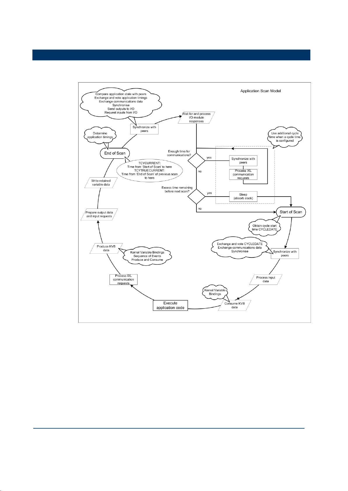
Application Scan Model
The application scan model for the AADvance controller is shown in the following
illustration:
Page 20

1-6
Document: 553633
ICSTT-RM405f-EN-P
Issue 07
Configuration Guide (AADvance Controller)
Scan Times
Module
Scan Time
T9401 Digital input module, 24V dc, 8 channel
Single
Dual
Triple
1.23ms
1.73ms
2.08ms
T9431 Analogue input module 24V dc, 8 channel
Single
Dual
Triple
1.26ms
1.91ms
2.33ms
T9451 Digital output module, 24V dc, 8 channel
Single
Dual
1.43ms
2.44ms
AADvance Workbench Sleep Period
57.2ms
Scan overhead per module
0.09ms
The following scan times were taken from a test system consisting of production
modules.
The tests did not measure the effect of logic complexity and communications loading.
The scan time is:
(Number of module groups x scan time shown above) + Sleep Period + (Total
modules x scan overhead)
The scan time will vary by up to +/- 5ms (not including the effect of logic and
communications).
Throughput time is the time from input change to output action. Due to the discrete
nature of the scan, the throughput time will vary between one and two scans.
Note: The AADvance application scan time is limited to a minimum of 64ms to allow
all processes to run. Small applications will report a scan time of approximately 57 61ms. Large applications may have longer scan times but each scan time will be
consistent to within approximately 5ms.
An example configuration scan time:
T9431 Analogue input simplex modules x 30
T9451 Digital output simplex modules x 18
Total I/O modules = 48
Estimated scan time = (30 x 1.23ms) + (18 x 1.43ms) + 57.2ms + (48 x 0.09ms)
= 125.1ms
Page 21

Document: 553633
ICSTT-RM405f-EN-P
Issue 07
1-7
Throughput time:
min = 125.1ms
Avg = 187.6ms
Max = 250.1ms
Page 22

Page 23

Document: 553633
ICSTT-RM405f-EN-P
Issue 07
2-1
This chapter provides the instructions to install and license the AADvance
In This Chapter
AADvance WorkbenchLicensing Options .................................................... 2-1
Install the AADvance Workbench and Utilities .......................................... 2-1
Add and Activate a New AADvance Workbench License ....................... 2-5
Updating or Upgrading an Existing License .................................................. 2-7
Chapter 2
Software Installation
Workbench.
AADvance WorkbenchLicensing Options
You can use the AADvance Workbench for a trial period of 30 days with a
promotional license. To use a fully operational version you must purchase a license key
from Rockwell Automation. License keys come in two forms:
T9082/3U Single User Hardware License: a hardware license key is a dongle
that is delivered with the software. To activate the license you insert the dongle
into the USB port of your computer. This type of license allows the license to be
moved to other PC's, but only the PC with the USB Dongle installed will allow the
Workbench to be started.
T9082/3D Single User Software License: a software license key (hard disk
key) is obtained and activated through the AADvance License Manager. This
type of license establishes the license on a specific PC or another PC, but only the
PC with the software key activated will allow the Workbench to be started.
When you purchase a single user license you can choose from the following feature
sets:
T9082 Multiscan (PRS): Single user, single controller license.
T9083 Distributed (PRD): Single user, multiple controllers license.
Network licenses are also available:
T9084U Network User License: A network license (USB dongle) allows the
users to license copies of the AADvance Workbench on PC's so long as they have
a continuous network connection to a central license server.
Install the AADvance Workbench and Utilities
When Installing a single user license you do not need to install the License Manager
separately unless you are running a network installation; You just need to run the
License Manager to activate or enable a license.
Page 24
2-2
Document: 553633
ICSTT-RM405f-EN-P
Issue 07
Configuration Guide (AADvance Controller)
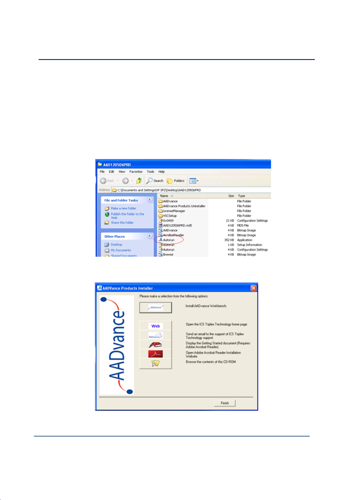
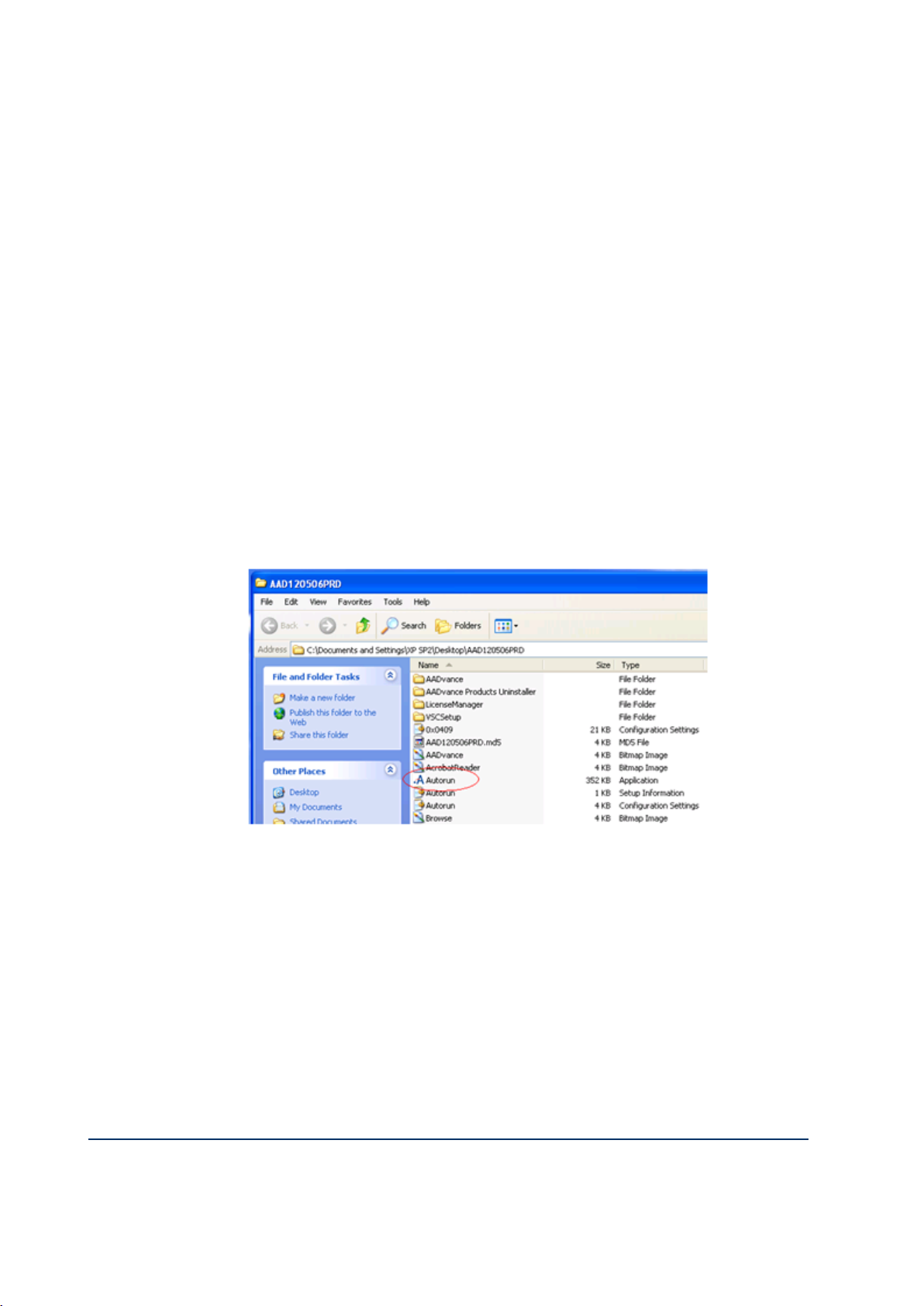
Installing Workbench Part Numbers: T9082U. T9082D, T9083U & T9083D
Notes:
You require "Admin" rights on the PC the Workbench is to be installed on.
The Install CD has an Autorun, so simply inserting the CD will launch the
AADvance Products Installer.
If however the Workbench is being installed using a downloaded CD image, to
launch the AADvance Products Installer you must run the Autorun
application from the following folder:
To install the Workbench and its Utilities do the following:
1) Click on the Install AADvance Workbench button.
Page 25
Document: 553633
ICSTT-RM405f-EN-P
Issue 07
2-3
Accept the License Agreement and the installation will commence.
The default is to install both the Workbench and the License Manager
components; we recommend proceeding with the defaults.
When the install commences you will be given the option of changing the
location for the install, we recommend you accept the default settings.
During the install you will be asked if you want shortcuts placed on your
desktop, simply answer yes or no depending on your preference.
When the installation is complete you will be prompted to restart the
computer, this must be done prior to using the Workbench.
Install Part Number T9084U Network License
Notes:
You require "Admin" rights on the PC the Workbench is to be installed on.
The Install CD has an Autorun, so simply inserting the CD will launch the
AADvance Products Installer.
If however the Workbench is being installed using a downloaded CD image, to
launch the AADvance Products Installer you must run the Autorun
application from the following folder:
To use Network based licensing, you have to install the Workbench and the
License Manager on any PC’s you wish to run the Workbench on and you have to
install the License Manager on the PC or Server that will act as the network
License Server.
1) Click on the Install AADvance Workbench button.
You must accept the License Agreement before the installation will commence.
The default is to install both the Workbench and the License Manager
components; we recommend proceeding with the defaults.
When the install commences you will be given the option of changing the
location for the install, we recommend you accept the default settings.
During the install you will be asked if you want shortcuts placed on your
desktop, simply answer yes or no depending on your preference.
Page 26

2-4
Document: 553633
ICSTT-RM405f-EN-P
Issue 07
Configuration Guide (AADvance Controller)
When the installation is complete you will be prompted to restart the
computer, this must be done prior to using the Workbench.
Install the License Manager on the Network License Server
1) Click on the Install AADvance Workbench button at the top of the list of the
AADvance Products Installer.
You must accept the License Agreement before the installation will commence.
2) Select the License Manager Only.
Note: The License Server can also function as a Workbench, if this is the intended
method of operation proceed with the defaults.
When the install commences you will be given the option of changing the
location for the install, we recommend you accept the default settings.
During the install you will be asked if you want shortcuts placed on your
desktop, simply answer yes or no depending on your preference.
When the installation is complete you will be prompted to restart the
computer, this must be done prior to using the Workbench.
Page 27
Document: 553633
ICSTT-RM405f-EN-P
Issue 07
2-5
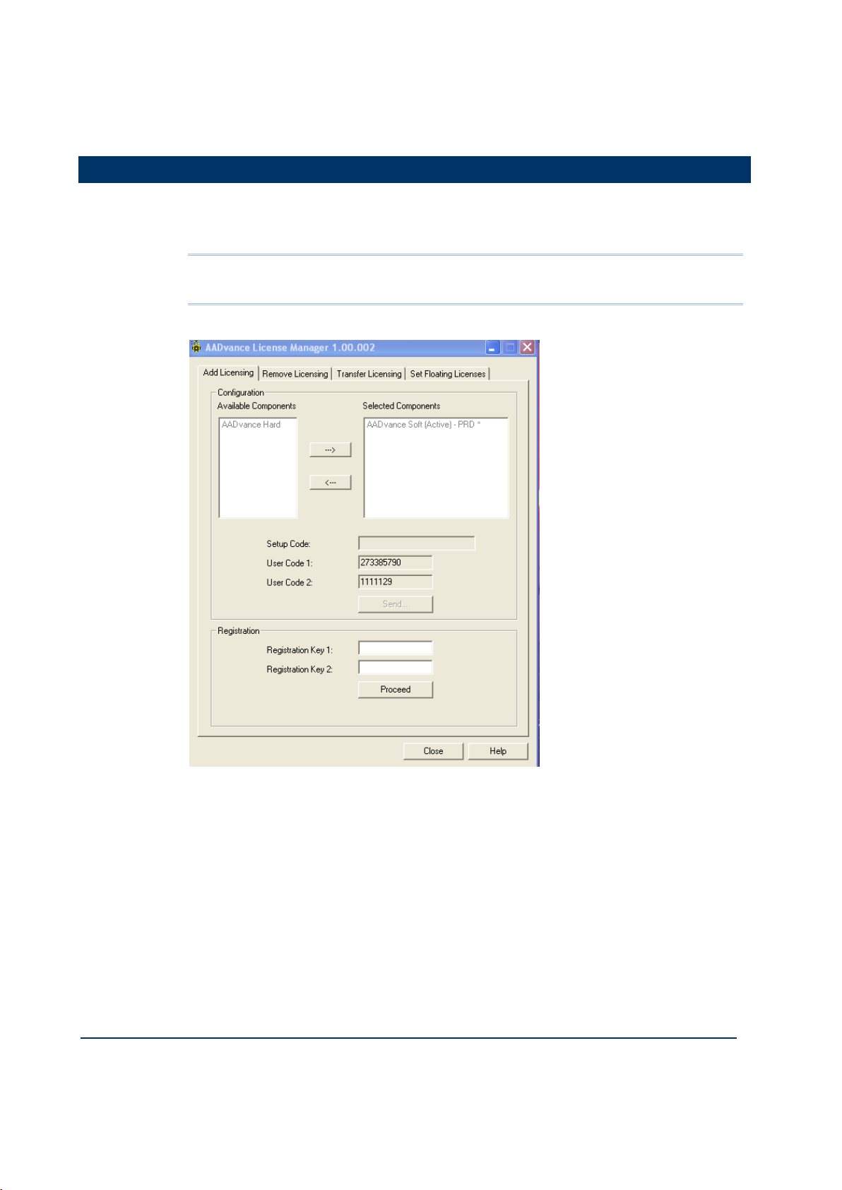
Add and Activate a New AADvance Workbench License
You use the following AADvance License Manager window to add and activate a new
Software (Disk Based) AADvance Workbench licenses. USB licenses are detected
automatically.
Note: You need only one set of user codes and registration keys to activate the
license key, irrespective of the feature set or number of licenses ordered.
To add a new license do the following:
1) From the Start menu select AADvance Licensing AADvance.
The AADvance License Manager dialog box opens.
2) Select the Add Licensing tab.
3) Select an AADvance Soft component from the Available Components, then
click the button to move the selection to the Selected Components
window.
Page 28
2-6
Document: 553633
ICSTT-RM405f-EN-P
Issue 07
Configuration Guide (AADvance Controller)
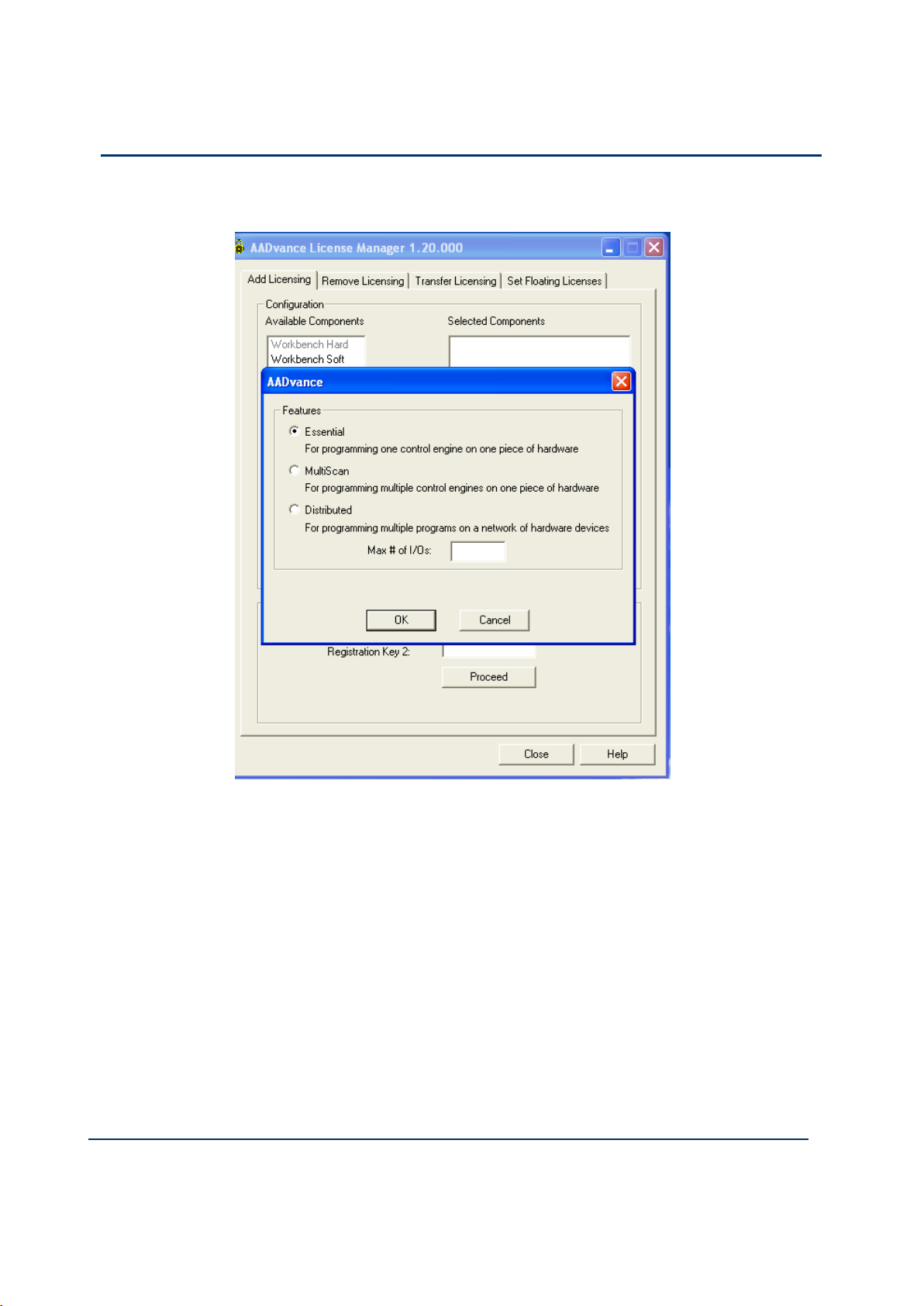
4) The AADvance license Features options appears.
5) Select the license feature and leave the Max#of I/Os blank. When you purchase a
single user license you can choose from the following feature sets:
T9082 Multiscan (PRS): Single user, single controller license.
T9083 Distributed (PRD): Single user, multiple controllers license.
6) A Setup Code and two User Codes appear in their respective fields.
7) Click Send.
A License Manager window opens telling you to register by email, click Yes.
8) At this point your email client may ask your permission to access an external email
address, click the Yes button
A pre-addressed email form opens containing the following:
- the selected components details
- setup code and both user codes
9) Enter the contact information and the purchase order number into the email form.
Page 29
Document: 553633
ICSTT-RM405f-EN-P
Issue 07
2-7
10) Send the email.
Note: If the computer does not have an email client configured, copy the text and send
from another computer.
The original Setup Codes and User Codes together with the new
Registration Keys are returned to you in an email.
1) Check that the Setup Code and User Codes are the same as the original ones.
2) Enter the Registration Keys into their respective fields, click Proceed.
The selected components appear grey in the Selected Components list.
3) Restart AADvance.
Updating or Upgrading an Existing License
You can update your current license by moving to newer version, or upgrade your
license by changing your feature set.
If you are using a hardware or software license you can update or upgrade it using
the AADvance License Manager.
Update or Upgrade a Hardware/Software License Key
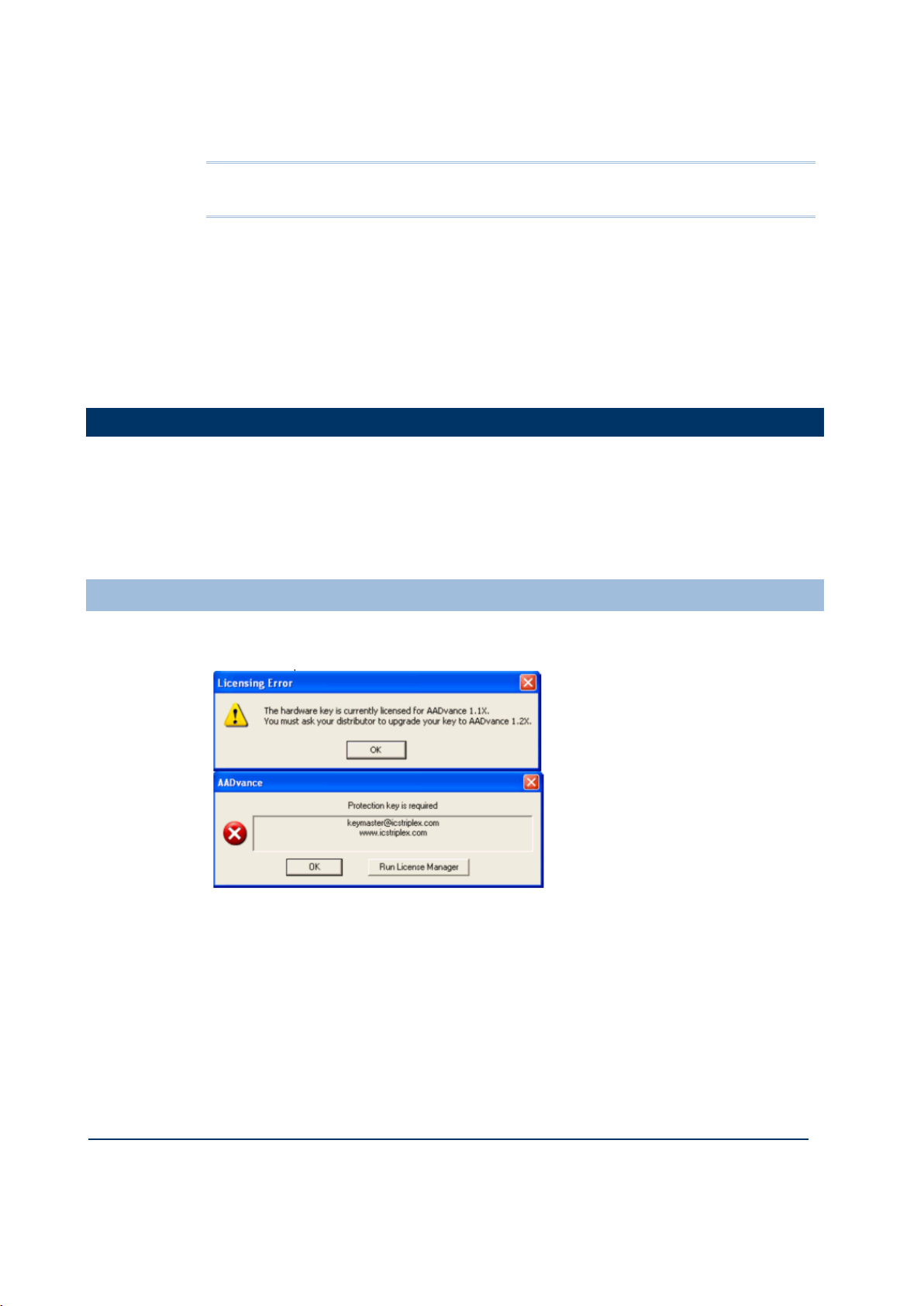
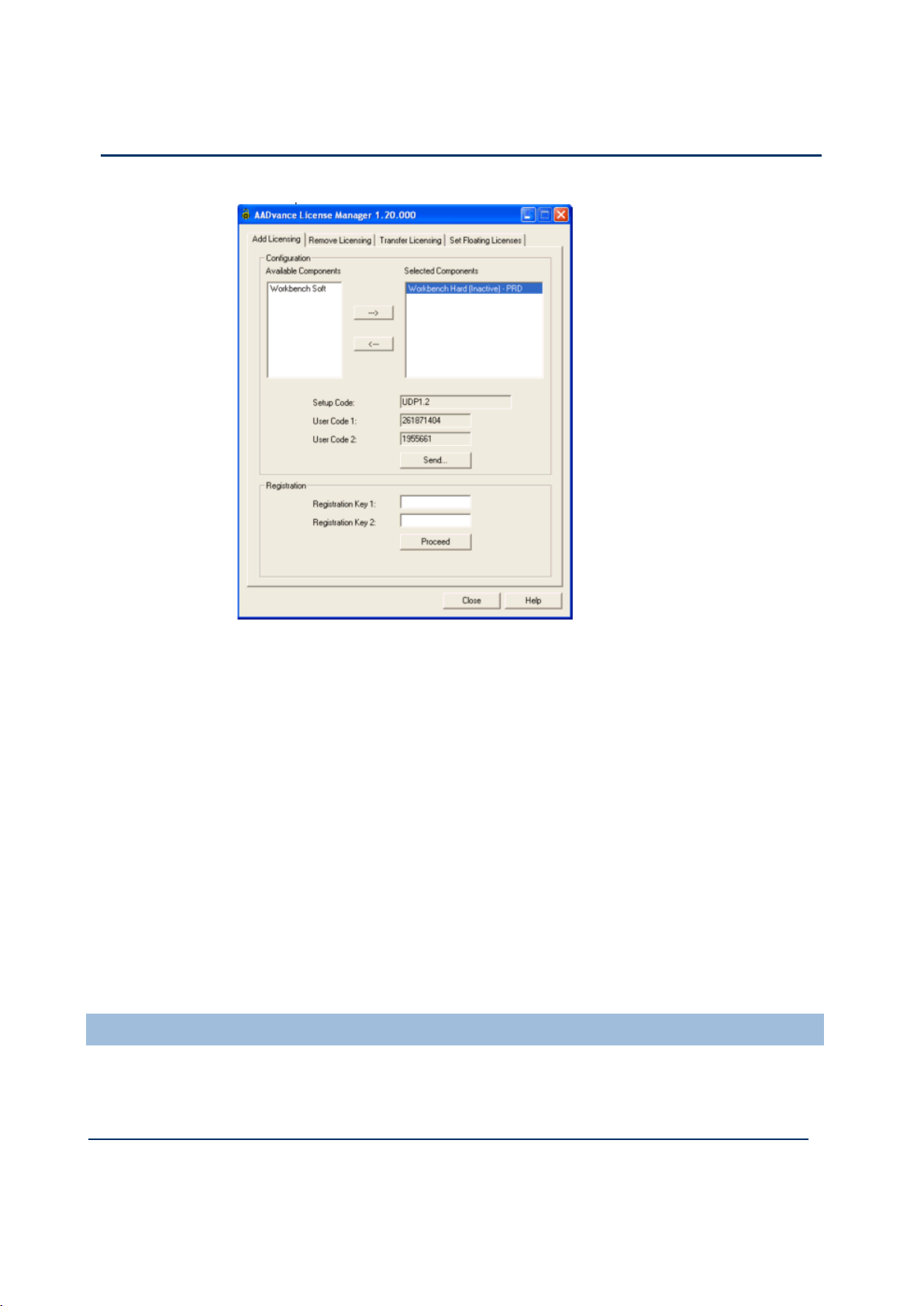
After upgrading the Workbench to Release 1.2 and opening it for the first time, a
message box will appear showing that the license needs to be upgraded.
1) From the Start menu select AADvance Licensing AADvance.
The AADvance License Manager dialog box opens with the UPP1.2 Setup
Code for a software license and the UDP1.2 Setup Code for a Hardware
license and the User Codes 1 & 2.
Page 30
2-8
Document: 553633
ICSTT-RM405f-EN-P
Issue 07
Configuration Guide (AADvance Controller)
2) Send the User Codes by email to keymaster@icstriplex.com.
3) If you are upgrading a hardware license key, leave it fitted.
You will be sent the Registration Keys 1 & 2.
4) Enter these keys in the two boxes and click Proceed.
Your license will be upgraded.
Multi-User Floating Hardware License
1. The Licensing Error message may not be automatically displayed, but you still need
to upgrade your license.
2. A 2-stage procedure must be followed:
first follow the above procedure to upgrade a license for a single user,
then send a second email to keymaster@icstriplex.com with the user codes
generated in the first step to create a multi-user license.
Using a Floating License Server
You can set up a networked PC as a server to provide floating AADvance licenses to
workstations on the same network. You can also set up a secondary server to provide
additional floating licenses or an alternative floating license source.
Page 31

Document: 553633
ICSTT-RM405f-EN-P
Issue 07
2-9
Set Up a Server for Hardware Floating Licenses
To set up a primary server for hardware floating licenses, do the following:
1) Insert the dongle supplied with the CD set into a USB or parallel port.
2) From the Start menu select AADvance Licensing
The License Manager dialog box opens.
3) Select the Set Floating Licenses tab.
4) Set the IP Address of the primary server and a port number.
5) Select one of the two options to start the server Manual or Automatic
(Automatic is recommended).
The Primary Server Status will show Stopped.
6) Click Start Server button.
The Server Status will show Licensed.
7) Repeat this procedure to set up a secondary server, if you have two floating
license servers acting as a backup pair.
Page 32

2-10
Document: 553633
ICSTT-RM405f-EN-P
Issue 07
Configuration Guide (AADvance Controller)
Set Access to Floating Licenses
To set access a floating license, do the following:
1) From the Start menu select AADvance Licensing.
The AADvance License Manager dialog box opens.
2) Select the Set Floating Licenses tab.
The Primary Server Status will show Licensed.
3) Set the IP address of the primary server and the port number.
4) Click Report to claim a license.
The Primary Server Status will show Licensed.
5) Repeat this procedure to set up a secondary server if two license servers have
been set up entering the Secondary IP Address and Port number.
6) Click Report to claim a license.
The Secondary Server will show Licensed.
7) Click Close.
Page 33

Document: 553633
ICSTT-RM405f-EN-P
Issue 07
3-1
This chapter describes the procedures for connecting the AADvance Workbench to
In This Chapter
Setting Up the Controller IP Address for AADvance Workbench
Communications ................................................................................................. 3-1
Chapter 3
Connecting the Workbench to the Controller
the controller so that the application can be downloaded.
Setting Up the Controller IP Address for AADvance Workbench Communications
The AADvance controller stores a resource number and IP address information.
These details have to match those defined in the AADvance Workbench for the
application. After you have configured these details the AADvance Workbench can
communicate with the controller. You use the AADvanceDiscover utility to set up
the controller for AADvance Workbench communications.
Controller IP Address Setting
The AADvanceDiscover Utilility uses a discovery and configuration protocol
(proprietary to Rockwell Automation) to set the controller IP address within the
AADvance Workbench and to scan the broadcast domain for other AADvance
controllers. The utility locates each controller by its unique MAC Address. Having
located a particular controller to be configured, the utility lets you configure the
resource number and IP Address to be stored in the controller; after you have done
this, the AADvance Workbench can communicate with the other controller.
AADvanceDiscover Utility
The AADvanceDiscover utility is installed when you install the AADvance
Workbench, and appears on the Start menu of the computer. Click on AADvance
Discover to start the AADvanceDiscover utility.
The AADvanceDiscover utility displays a list of the AADvance controllers on the
broadcast network, and reports a status for each one:
Configurable
Locked
No response
Page 34

3-2
Document: 553633
ICSTT-RM405f-EN-P
Issue 07
Configuration Guide (AADvance Controller)
Double-clicking on an entry in the list lets you inspect the resource and IP address
settings for a controller. There is also a Refresh button, which makes a scan of the
network and creates a new list.
A controller is configurable when the program enable key is present (this plugs into
the KEY connector on the processor base unit) and either no application is loaded or
an application is loaded but not running. The status will be locked if the controller
reports that one or more of these criteria has not been met.
If the AADvanceDiscover utility reports a status of 'no response' for a controller,
either the controller has been turned off or the communications between the
computer running the utility and the controller have failed. Check the power to the
controller and check the connection, and click the Refresh button.
The AADvanceDiscover utility also reports a status of 'in progress' and 'Pending
restart'. 'In progress' appears while the controller accepts new settings. 'Pending
restart' means the controller is waiting for manual intervention from you; cycle the
power to the controller.
The AADvanceDiscover utility will also allow you to save configurations that you
can re-load in the future as required. It can also be used to enable the Ethernet
Forwarding feature.
About Discover Communications
AADvanceDiscover uses DCP (Discovery & Configuration Protocol), not TCP. This is
a general purpose protocol which allows AADvance controllers without an IP address
to be configured on a network without having to set switches, or connect a serial
cable to preset an IP address.
DCP communications may be blocked or mis-routed by Windows or by other
network devices. You may find that systems known to be on the network do not
appear in the list, or appear only randomly. There is no point in attempting any 'ping'
commands - if a system is not yet programmed it will not respond, and if it is already
programmed, you will just prove it is programmed.
Note: DCP messaging will not work across network bridges and routers.
Page 35

Document: 553633
ICSTT-RM405f-EN-P
Issue 07
3-3
Discover Communications Fault-Finding
This procedure describes how to activate communications using the Discover tool.
After completing the steps, refresh the Discover tool's list of modules to test for
communications.
1) Ensure that the Ethernet cable is plugged into a socket above a fitted AADvance
controller – communications will not ‘pass through’ unused slots.
2) Ensure that the controller is activated by turning the locking bar. Wait for the
Ready LED to go green before refreshing the Discover tool. (The communications
tasks are not active until it is 'Ready').
3) Do not use an office network. Use an isolated hub or switch between the
computer and AADvance controller. Check that the hub/switch has LEDs lit for
the ports to both computer and controller, showing that the ports are working.
4) Open the Network Connections window. Open the Properties of the computer’s
network adapter (as used for configuring AADvance). Un-tick all protocol "items"
which are not immediately necessary, especially "Check Point SecuRemote" and
"iPass Protocol" (if present). You will need to leave "Internet Protocol" (or) "IPv4"
and "IPv6", "Client for Microsoft Networks", "File and Printer Sharing" and
"Network Monitor Driver" (if present) for normal Windows operation.
5) Disable the Windows Firewall, or any third-party firewalls and shields.
6) If you are using a laptop, disable Wireless. If you have more than one network
connection, disable the one you are not using. The Discover tool installed with
AADvance Workbench release 1.2 (1.20.109) will not discover with more than
one network connection available.
Configure the Controller Resource Number
When you build a new AADvance controller, or install a new 9100 processor base
unit, you have to configure the resource number stored in the controller. This is a kind
of device address, and it must also be configured in the application.
The procedure to configure the resource number uses the AADvanceDiscover
utility. To set the resource number do the following:
1) Make a note of the controller's MAC address (Controller ID); this is shown on
a label on the processor base unit. Install at least one 9110 processor module into
the processor base unit.
2) Make sure the program enable key is inserted in the KEY connector on the
processor base unit.
3) Start the AADvDiscover tool from the Start menu:
Start All Programs AADvance AADvance Discover.
Page 36

3-4
Document: 553633
ICSTT-RM405f-EN-P
Issue 07
Configuration Guide (AADvance Controller)
The AADvanceDiscover utility scans the network for controllers, and
creates a list.
4) Locate the controller in the list and make sure that the status of the controller is
Configurable.
5) Double-click on the MAC address in the Controller ID field.
The resource and IP Address dialog box opens.
6) Enter the resource value into the Resource Number field, click Apply.
Returning to the main window of the utility, the controller status will show
Pending Restart.
7) To complete the update, cycle the power to the controller.
Page 37

Document: 553633
ICSTT-RM405f-EN-P
Issue 07
3-5
8) Refresh the screen to confirm that the new resource number is displayed in the
resource field and the controller status is configurable.
The Resource Number must also be configured in the application, in the
Resource Properties.
Configure the IP Address in the Controller
When you build a new AADvance controller, or install a new 9100 processor base
unit, you have to configure the IP Address stored in the controller.
The procedure to configure the IP Address uses the AADvanceDiscover utility.
Changes take effect immediately and you do not have to restart the controller. To set
the IP Address do the following:
1) Make a note of the controller's MAC address (Controller ID); this is shown on a
label on the processor base unit. Install at least one 9110 processor module into
the processor base unit.
2) Make sure the program enable key is inserted in the KEY connector on the
processor base unit.
3) Start the AADvanceDiscover tool from the Start menu:
Start All Programs AADvance AADvance Discover.
The AADvanceDiscover utility scans the network for controllers, and
creates a list.
4) Locate the controller in the list and make sure that the status of the controller is
Configurable.
5) Double-click on the MAC address in the Controller ID field.
The resource and IP address dialog box opens.
Page 38

3-6
Document: 553633
ICSTT-RM405f-EN-P
Issue 07
Configuration Guide (AADvance Controller)
6) Enter the IP Address and Subnet Mask into the fields for each Ethernet port.
7) Enter the Gateway values for each processor module, click Apply.
Returning to the main window of the utility, the controller status will show In
Progress and then Configurable.
The controller uses the new settings.
Page 39

Document: 553633
ICSTT-RM405f-EN-P
Issue 07
3-7
Save and Load a Configuration
When you have entered the IP Address details you can now save the configuration:
1) Click Save after you have entered your required configuration.
Page 40

3-8
Document: 553633
ICSTT-RM405f-EN-P
Issue 07
Configuration Guide (AADvance Controller)
2) Give the configuration a name and save it to a suitable location.
To reload a saved configuration file:
1) Open the AADvanceDiscover utility
2) Double click on a MAC address to open the Configuration dialog box.
3) Select the Configuration file at the location it was saved.
4) Click Load to load the saved configuration.
Page 41

Document: 553633
ICSTT-RM405f-EN-P
Issue 07
4-1
This chapter describes the process to configure the processor modules:
In This Chapter
View Module Firmware Versions .................................................................... 4-1
ControlFLASH Firmware Upgrades ............................................................... 4-5
Configure Controller Type (Standard or Eurocard) ................................ 4-19
Configure the Top-level Process Safety Time (PST) ................................ 4-20
Configure the Processor Battery Alarm ..................................................... 4-21
Configure the Serial Ports .............................................................................. 4-22
Time Synchronization (SNTP) ....................................................................... 4-24
Using the Controller as a Modbus Slave ..................................................... 4-27
Transparent Communication Interface (TCI) ............................................ 4-30
DiffServ Configuration ..................................................................................... 4-32
Ethernet Forwarding ........................................................................................ 4-34
About T9110 Processor Variables................................................................ 4-36
Set the Processor clock .................................................................................. 4-54
Chapter 4
Configuring the Processor Modules
View Module Firmware Versions
Using the AADvance Workbench you can view the module firmware information on
screen and save this information with your project. Using an update function view the
latest information and save it as an external text file.
To do this proceed as follows:
Note: To view the firmware version numbers of the modules you must be connected
using Debug to a running controller.
1) Select the Equipment View tab.
2) Select the desired configuration node Config4(9000 Series Controller) in
example shown below.
3) Select the Version Information tab.
The version information window appears. If the version information has
previously been requested and saved (applied) then it will be visible in this
window.
Page 42

4-2
Document: 553633
ICSTT-RM405f-EN-P
Issue 07
Configuration Guide (AADvance Controller)
4) Click the Update button.
Page 43

Document: 553633
ICSTT-RM405f-EN-P
Issue 07
4-3
The window now shows your controller's current firmware version information.
The information displayed is as follows:
MAC Addresses - MAC addresses for the controllers. There are two addresses
per controller set by the BUSP chip inserted into the processor base unit;
However, 6 MAC addresses are displayed regardless if the system is a Single, Dual
or Triple processor system.
The module Information is as follows:
Slot - the slot the module has been allocated
Module - the module identity
Serial - the module hardware serial number
Versions - The firmware versions in the module
1) Click Apply
The information is saved with the project so that next time the project is
opened you can view it.
2) To save the information to a text file select the Save As button.
3) A window opens with a default text file name Version_Report.txt; Enter your
own file name and click Save.
Page 44

4-4
Document: 553633
ICSTT-RM405f-EN-P
Issue 07
Configuration Guide (AADvance Controller)
The saved text file can be viewed in Notepad.
Page 45

Document: 553633
ICSTT-RM405f-EN-P
Issue 07
4-5
ControlFLASH Firmware Upgrades
WARNING
FIRMWARE UPGRADE DANGER TO A RUNNING SYSTEM
Do not attempt to upgrade firmware on a running system. Control
FLASH will not warn you that a system is running and you will lose
control of the application when the system reboots.
The AADvance controller supports upgrades of processor module firmware by using
the ControlFLASH utility (I/O module upgrades using ControlFLASH are not currently
supported in this release.)
Upgrading the processors is a two stage process:
Stage 1: Run the latest version of 350720_xxx_ControlFLASH.msi program to
install the ControlFLASH firmware upgrade kit for the Recovery Mode on your
PC. Then run the ControlFLASH utility to upgrade your processor module and
install the Recovery Mode. If your module is delivered with the Recovery Mode
installed then this stage is not necessary.
Note: Stage 1 must be done individually on each processor; it does not matter if you
download the Recovery Mode one at a time in a specific slot or in their own slots.
What You need
Stage 2: Reboot the processor and enter the Recovery Mode. the run the latest
version of 354400_xxxx_ControlFLASH.msi program to install the ControlFLASH
to upgrade your processor's OS, FPGA, LSP and BUSP.
Note: When Stage 1 is completed ControlFLASH can be used to upgrade three
processor modules in the same processor base unit all at the same time.
You will need the ControlFLASH firmware upgrade kit.
Firmware for the processors being upgraded.
ControlFLASH programming tool, along with its required support drivers and on
line HELP.
Quick Start and RSLinx Classic Lite software or better.
To install and configure the ControlFLASH utility refer to the Rockwell Automation
ControlFLASH Upgrade Kit documentation, Publication No: 1756-UM105C-EN-E
March 2012 available from the Rockwell Automation Literature Library.
RSLinx Software
Page 46

4-6
Document: 553633
ICSTT-RM405f-EN-P
Issue 07
Configuration Guide (AADvance Controller)
The RSLinx Classic Lite software must be installed before you can install the
ControlFLASH software. RSLinx software is a communications software package that
you can use with a wide variety of rockwell automation applications and hardware. The
ControlFLASH software uses the RSLinx Classic Lite software to communicate over
Data highway Plus, DFI, DH485, ControlNet, DeviceNet and Ethernet networks.
Before installing the ControlFLASH Firmware Kit, RSLinx must be configured with the
IP address of the controller you wish to upgrade. Ensure that when you run the RSLinx
software from the "Communications" menu click "Configure Drivers". Select a
driver of type "Ethernet Devices" and add the required IP address to the list.
Stage 1: Installing the ControlFLASH Firmware
This procedure will install Recovery Mode and Secondary Boot firmware.
1) Run the ‘350720_102_ControlFLASH.msi file.
2) Click Next
3) Read and agree to the license and click Next
Page 47

Document: 553633
ICSTT-RM405f-EN-P
Issue 07
4-7
4) Click Browse to select the location of the installation or Next to select the
default location.
5) Click Next to start the installation.
Page 48

4-8
Document: 553633
ICSTT-RM405f-EN-P
Issue 07
Configuration Guide (AADvance Controller)
ControlFLASH installs.
6) To launch ControlFLASH select the Yes I want to launch controlFLASH
option, then click Close.
Page 49

Document: 553633
ICSTT-RM405f-EN-P
Issue 07
4-9
WARNING
FIRMWARE UPGRADE DANGER TO A RUNNING SYSTEM
Do not attempt to upgrade firmware on a running system. Control
FLASH will not warn you that a system is running and you will lose
control of the application when the system reboots.
ControlFLASH will launch and you can now upgrade the Processor Module
firmware.
Upgrade the Processor Module Recovery Mode Firmware
This is the recommended procedure to upgrade the processor module firmware using
the ControlFLASH Utility.
Note: ControlFLASH can upgrade 3 processor modules at once when installed into a
9100 base unit and they are in the Recovery Mode. To do this press and hold the
Fault Reset button on all three processors when they are being powered up during a
power on/off cycle until the AUX LED goes Amber.
1) Run the ControlFLASH software by either:
Launching from the installation
Double clicking the desktop icon
Launching from the Start button
Page 50
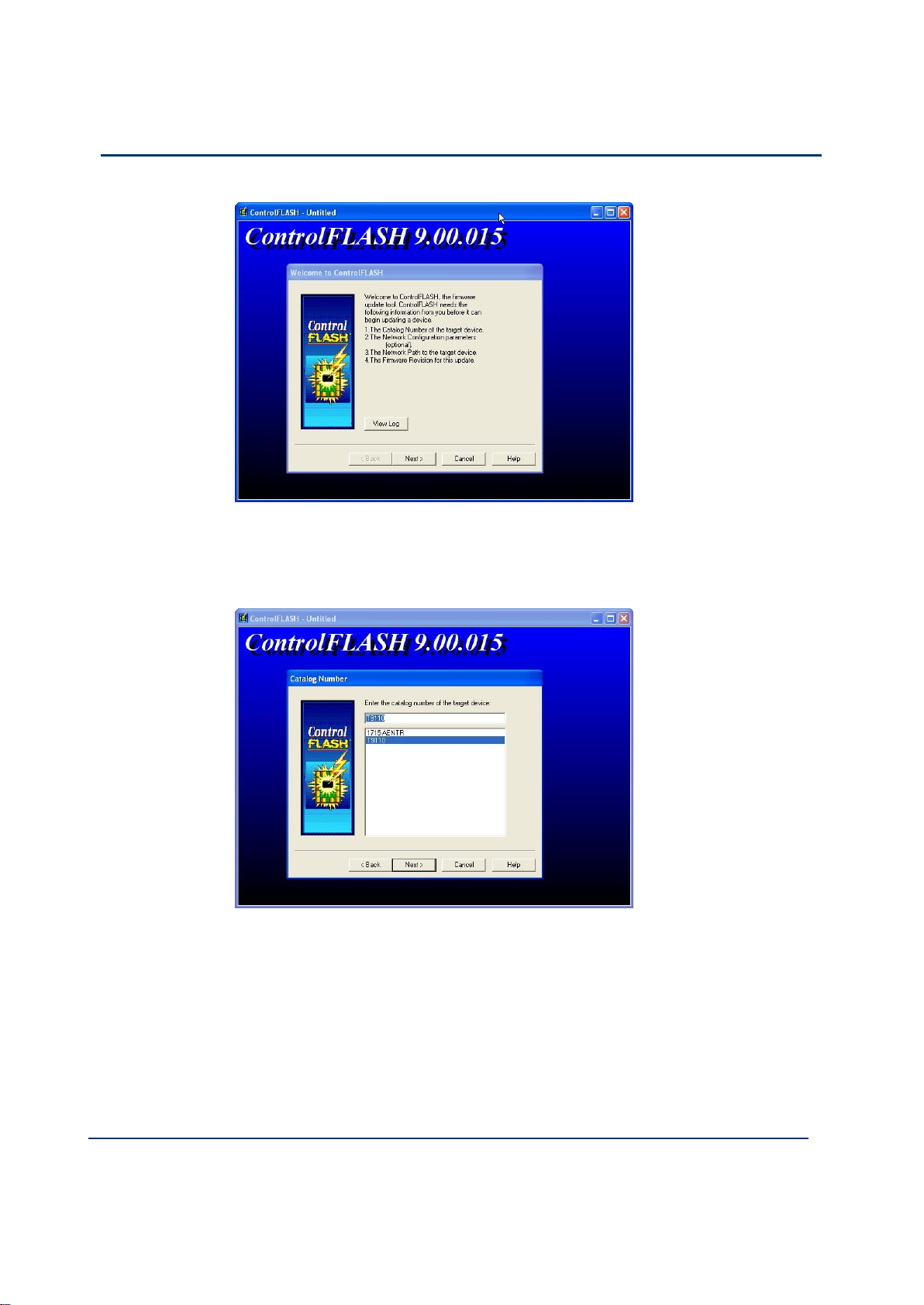
4-10
Document: 553633
ICSTT-RM405f-EN-P
Issue 07
Configuration Guide (AADvance Controller)
2) Click Next.
3) Select T9110 from the list.
4) Browse to the device in the RSLinx window
Page 51

Document: 553633
ICSTT-RM405f-EN-P
Issue 07
4-11
5) Select the firmware revision for the latest Release.
6) Check the summary details, click Finish
Page 52

4-12
Document: 553633
ICSTT-RM405f-EN-P
Issue 07
Configuration Guide (AADvance Controller)
The continue message is displayed:
7) Click Yes to continue with the update
A progress bar is displayed
Page 53

Document: 553633
ICSTT-RM405f-EN-P
Issue 07
4-13
When the progress bar reaches the end, it may take several minutes for the
next screen to appear.
Note:
It has not locked up! Wait until the next message box appears !
You may get a "Comms error message" as AADvance processors do not
automatically reboot as ControlFLASH expects them to but the firmware
download should have completed correctly.
8) Click OK.
Wait another couple of minutes and the same message will appear again.
9) Click OK.
Page 54

4-14
Document: 553633
ICSTT-RM405f-EN-P
Issue 07
Configuration Guide (AADvance Controller)
The following message now appears.
10) Click OK and another error message is displayed.
11) Click OK then Cancel to Exit ControlFLASH.
12) Reboot the processor module by switching the power OFF then ON and hold in
the Fault Reset button as the module reboots until the Aux LED goes amber.
The processor module(s) will reboot into the Recovery Mode indicated by the
following LED states on the processor module.
Healthy Green (dependent on Module health)
Ready Amber
Run Amber
System Health Green (dependent on system health)
Force Amber
Aux Amber
Stage 2: Installing the ControlFLASH Firmware Kit for OS, FPGA, LSP and BUSP
This procedure describes how to upgrade the Processor Firmware for OS, FPGA, LSP
and BUSP.
The procedure that follows is basically the same as for stage 1.
1) Run the 354400_102_ControlFLASH.msi file.
2) Click NEXT.
3) Read and agree the License.
Page 55

Document: 553633
ICSTT-RM405f-EN-P
Issue 07
4-15
4) Click Browse to select the location of the installation or Next to choose the
WARNING
FIRMWARE UPGRADE DANGER TO A RUNNING SYSTEM
Do not attempt to upgrade firmware on a running system. Control
FLASH will not warn you that a system is running and you will lose
control of the application when the system reboots.
default location.
5) Click Next to confirm the installation.
ControlFLASH installs and shows the progress bar.
6) Click Yes I want to launch ControlFLASH, then click Close.
Upgrade Processor OS, FPGAFPGA, LSP and BUSP Firmware
This procedure describes how to upgrade the processor module firmware using
ControlFLASH.
Note: ControlFLASH can upgrade 3 processor modules at once when installed into a
9100 base unit.
1) Run the ControlFLASH software by either:
Launching from the installation
Double clicking the desktop icon
Launching from the Start button
2) Click Next.
3) Select T9110 from the list.
Page 56

4-16
Document: 553633
ICSTT-RM405f-EN-P
Issue 07
Configuration Guide (AADvance Controller)
4) Browse to the device in the RSLinx window
5) Select the firmware revision for the latest Release.
Page 57

Document: 553633
ICSTT-RM405f-EN-P
Issue 07
4-17
6) Check the summary details, click Finish
The continue message is displayed:
7) Click Yes to continue with the update
Page 58

4-18
Document: 553633
ICSTT-RM405f-EN-P
Issue 07
Configuration Guide (AADvance Controller)
A progress bar is displayed
Note: if the processor is not in the Recovery Mode the following error is displayed.
Follow the procedure in Stage 1 to download the recovery Mode.
Page 59

Document: 553633
ICSTT-RM405f-EN-P
Issue 07
4-19
After the progress bar reaches the end, it may take several minutes for the
next screen to appear.
Use the View Module Firmware Versions procedure to verify that the upgrade
has worked.
Configure Controller Type (Standard or Eurocard)
The controller can be configured as a standard AADvance controller, a Eurocard
controller or a mixture of both.
To configure the controller type, do the following:
1) Select the I/O Wiring icon .
2) Right click on Config1 (9000 Series Controller).
3) Select Set Configuration Type Standard or Eurocard or Mixed.
Page 60

4-20
Document: 553633
ICSTT-RM405f-EN-P
Issue 07
Configuration Guide (AADvance Controller)
Note: Selecting Standard or Mixed will configure 48 empty IOB IO slots for I/O
modules (IOB IO Bus 1 and IO Bus 2); selecting Eurocard will configure 18 empty
slots on IOB IO Bus 1.
Configure the Top-level Process Safety Time (PST)
The PST setting defines the maximum time that the processor will allow the outputs
to remain in the ON state in the event of certain internal diagnostic faults or
systematic application faults. If PST expires the system will go to its safe state.
You have to specify the PST for the whole controller. This is a top level setting, which
you make once for all the T9110 processor modules.
Note: Groups of I/O modules can inherit this setting, or use an I/O module specific
PST setting instead, however this setting cannot exceed the top level setting. For a
large installation with a high number of I/O modules it is recommended that you set
the PST or the Processor a minimum of 1.5s. This is because for a larger installation
the education process for a second or third processor module can take quite a long
time.
To set the top-level process safety time do the following:
1) Select the 9110 Processor in the Equipment tree view.
The 9110 Module Editor opens.
2) Select the 9110 tab.
3) Enter the time value into the Process Safety Time field. Choose from the
following range of values:
Minimum: 1500ms
Maximum: 60,000ms (60 seconds)
Note: If you specify a process safety time below the application execution time,
the application will not run. The default is 2,500ms.
4) Click Apply.
Page 61

Document: 553633
ICSTT-RM405f-EN-P
Issue 07
4-21
Set PST to its Default Value
You can reset the PST to its default value, do the following:
1) Select the 9110 Processor in the Equipment tree view.
The 9110 Module Editor opens.
2) Select the 9110 tab.
3) Clear the entry in the Process Safety Time field.
4) Press return.
The Process Safety Time will change to its default value.
Configure the Processor Battery Alarm
The 9110 Module Editor includes a configuration setting for the battery alarm. It can
be set to Enabled or Disabled as required.
1) Select the 9110 Processor in the Equipment view.
2) Select the 9110 tab on the 9110 Module editor .
3) Select the Battery Alarm row and the required option.
Page 62
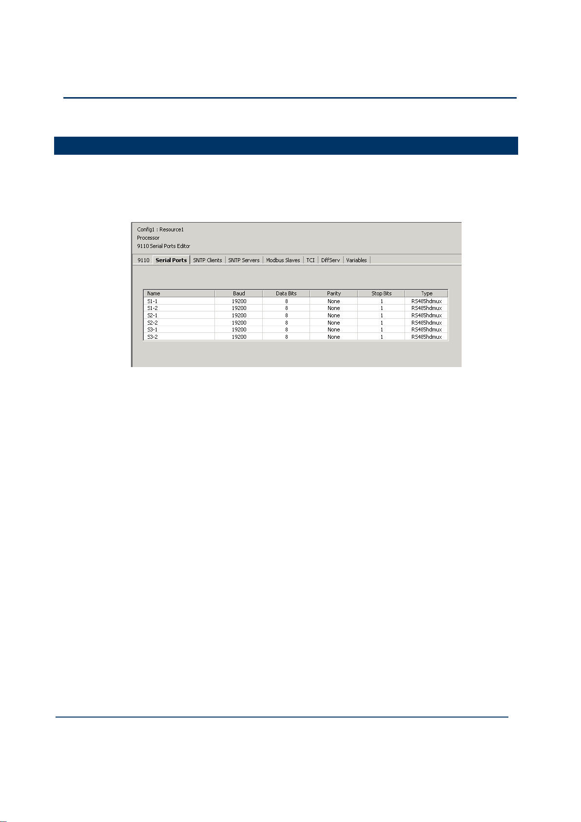
4-22
Document: 553633
ICSTT-RM405f-EN-P
Issue 07
Configuration Guide (AADvance Controller)
Configure the Serial Ports
The AADvance controller provides up to six serial communication ports, two for each
T9110 processor module present. .
The serial port settings define the protocol ('type') and the data characteristics of each
of the serial ports. To configure the serial ports do the following:
1) Select the Serial Ports tab.
The Serial Ports Editor dialog box opens.
2) Select the communication parameters from the drop down lists, click Apply.
3) To restore the default values, click Default then Apply.
Page 63

Document: 553633
ICSTT-RM405f-EN-P
Issue 07
4-23
Type
Description
RS485fd
Full-duplex, 4-wire connection with separate buses for
transmit and receive
RS485fdmux
Full-duplex, 4-wire connection with separate buses for
transmit and receive and tri-state outputs on the
transmit connections
RS485hdmux
Half duplex, 2-wire connection
Description
Value(s)
Default
Remarks
Baud
1,200; 2,400; 4,800;
9,600; 19,200; 38,400;
57,600; 76,800 or
115,200
19,200
Data Bits
5 to 8
8 Parity
None, Odd or Even
None
Stop Bits
1 or 2
1
Type
RS485fd
RS485fdmux
RS485hdmux
RS485hdmux
'fd' means 'full duplex'
'hd' means 'half duplex'
Serial Port Protocols
The serial ports support the protocols listed in the table.
Table 1: Serial Port Protocols
Serial Port Parameters
Each serial port on the AADvance controller supports the set of control parameters as
detailed in the table.
Table 2: Controller Serial Port Parameters
Note: Most systems use two bits after each data byte. The two bits are either a parity
bit (odd or even) and one stop bit, or no parity and two stop bits.
Page 64

4-24
Document: 553633
ICSTT-RM405f-EN-P
Issue 07
Configuration Guide (AADvance Controller)
Time Synchronization (SNTP)
The AADvance controller supports the Simple Network Time Protocol (SNTP)
service that can circulate an accurate time around the network. It can be configured to
operate as a SNTP client or server.
As an SNTP client the controller will accept the current time from external Network
Time Protocol (NTP) and SNTP network time servers. The SNTP clients settings
tell the controller the IP address of the external server; the version of SNTP offered
by the server; and the operating mode for the time synchronization signal that the
processors will use for their real time clock. As a client the processor module can be
configured as a unicast or broadcast client.
The AADvance controller can also fulfill the role of one or more SNTP servers (one
for each processor module) to provide a network time signal throughout the network.
To enable server time on an interface it is necessary to specify the direct broadcast
address for that interface. This works for broadcast or unicast modes and when
configured as a broadcast server it can respond to Unicast requests from clients.
Note: To set up SNTP you need to connect your controller to a suitable network
using one of the Ethernet ports. The network must be connected to an external NTP
server or have NTP loaded on to it.
Configure the Controller as an SNTP Client
To configure the SNTP clients service do the following:
1) Select the SNTP Clients tab.
The SNTP Clients Editor dialog box opens.
2) Set the E1-1 and E1-2 Address fields to the IP addresses of the network time
server.
Page 65

Document: 553633
ICSTT-RM405f-EN-P
Issue 07
4-25
Note: The first address represents that of the primary server and the second one
the secondary server for each processor module. At start up the SNTP client will
choose the primary server of the "lowest" slice; if no primary signal is valid the
SNTP client looks for an active secondary server signal.
For non-fault tolerant operation, define one SNTP server for only one
processor. The other processors will automatically synchronize to it and will
inherit the time.
For fault-tolerant SNTP client operation, define more than one server address.
3) Select the server Version.
Choose SNTPv1, SNTPv2, SNTPv3, SNTPv4 or Unknown.
If you do not know the version of NTP/SNTP that the server offers, choose
Unknown. This will disable some validation of the incoming signal.
4) Set the Mode to Unicast or Broadcast as required.
In Broadcast mode the SNTP client will passively wait for regular broadcasts
from the server. This reduces network traffic and hence the load on the
servers.
In Unicast mode the SNTP client will actively poll as many servers as are
configured every few seconds and use their responses. The polling rate (19s) is
based on the drift rate of the real-time clock and cannot be configured.
5) Click Apply.
Configure the Controller as an SNTP Server
To configure the SNTP servers service do the following:
1) Select the SNTP Servers tab.
The SNTP Server Editor dialog box opens.
2) Select the Unicast or Broadcast mode.
Page 66

4-26
Document: 553633
ICSTT-RM405f-EN-P
Issue 07
Configuration Guide (AADvance Controller)
If you select Unicast mode for a processor the controller will wait to be
polled by a client and then respond with a time signal; it will not broadcast any
time signals.
If you select Broadcast mode for a processor the controller will regularly
braodcast: it will also respond to unicast polling requests on that interface.
Note: If you set a processor Broadcast IP Address to zero (0.0.0.0) it will disable
the server on that interface.
3) Set the Broadcast IP Address for the network.
4) Repeat steps 2 and 3 for each additional processor module.
5) Click Apply.
Page 67

Document: 553633
ICSTT-RM405f-EN-P
Issue 07
4-27
Using the Controller as a Modbus Slave
The AADvance controller can operate as a Modbus slave, supporting up to ten
Modbus slaves on each 9110 processor module. This gives a capacity of thirty
Modbus slaves for a controller with three processor modules.
Note: As a Modbus slave device, the controller only transmits data upon a request
from a Modbus master, and does not communicate with other slaves.
Support for Modbus Slave Exceptions
When the AADvance controller operates as a Modbus slave, it can raise these
exception codes:
Code 01: Illegal Function
The function code received in the query is not an allowable action for the slave. If a
Poll Program Complete command was issued, this code indicates that no program
function preceded it.
Code 01 represents a function that the AADvance controller does not recognize or
does not support.
Code 02: Illegal Data Address
The data address received in the query is not an allowable address for the slave.
The AADvance controller raises code 02 when a request specifies an address outside
the 16-bit range 0 to 65,535. The exception occurs if the request specifies the address
implictly ('give me the 20 registers from address 65,530') or explicitly (give me the
register at address 65,536').
Code 03: Illegal Data Value\
A value contained in the query data field is not an allowable value for the slave.
The AADvance controller can raise code 03 only on boolean (coil) writes.
Code 04: Slave Device Failure
An unrecoverable error occurred while the slave was attempting to perform the
requested action.
Code 04 represents an internal error within the AADvance controller.
Code 06: Slave Device Busy
The slave is engaged in processing a long-duration program command. The master
should retransmit the message later when the slave is free.
The AADvance controller can be 'busy' and thus raise code 06 while it is waiting for
its application to download or to start. The controller can be report itself to be busy
for up to 30 seconds; after this period, the controller will cease to respond.
Page 68

4-28
Document: 553633
ICSTT-RM405f-EN-P
Issue 07
Configuration Guide (AADvance Controller)
Configure the Controller Modbus Slaves
You have to configure the communication parameters for each Modbus slave you
implement within the AADvance controller.
To configure a Modbus Slave do the following:
1) Select the Modbus Slaves tab.
The 9110 Modbus Slaves Editor dialog box opens.
2) In the Name column, locate the processor and slave you wish to configure.
3) Set the Connection field, click Apply.
The Id, Port and Protocol fields are set to their default values.
4) If you set the Connection to a serial port, the Id field represents the Slave ID; set
the Id field or accept the default value.
Page 69

Document: 553633
ICSTT-RM405f-EN-P
Issue 07
4-29
Note: The Port field does not apply for a serial connection, and is disabled.
Description
Value(s)
Default
Remarks
Connection
Not Configured, Sn-1, Sn-2,
Ethernet (†)
Not
Configured
Id
1 to 247
(serial);
1 to 255
(Ethernet)
1
(serial);
255
(Ethernet)
Represents the Slave ID
for a serial connection
Represents the Unit ID for
an Ethernet connection
Port
0 to 65,535
2000
Only used with Ethernet
connections
Description
Value(s)
Default
Remarks
Connection
Not Configured, Ethernet
Not
Configured
5) If you set the Connection to Ethernet, do the following:
Set the Protocol field, click Apply.
Note:As a Modbus slave, the controller supports Modbus RTU, using a serial or
Ethernet connection; and Modbus TCP, using an Ethernet connection. You can
configure a combination of connections for the Modbus slaves, subject to a
limitation of no more than two Modbus RTU slaves using serial communications
for each processor.
The Id field represents the Unit ID; set the Id field or accept the default value.
The default setting for the Port field suits most systems; occasionally, you will
have to adjust it. Make sure the Port field matches the port expected by the
Modbus master.
If the Port field is set to 502, Modbus TCP protocol is enabled. All other settings
of the Port field will enable Modbus RTU protocol packaged as a serial stream
over Ethernet. This can be converted back to a serial connection using a standard
terminal server.
Note: The range of values accepted for the Id field, and the default value for the
Port field, vary according to the protocol selected.
6) Click Apply.
Modbus Slave Communication Parameters
Each Modbus slave has a series of communication parameters as detailed in the tables.
Table 3: Modbus RTU Slave Parameters
Table 4: Modbus TCP Slave Parameters
Note: (†) The letter 'n' identifies the processor module:
1 = processor A, 2 = processor B, 3 = processor C.
Page 70

4-30
Document: 553633
ICSTT-RM405f-EN-P
Issue 07
Configuration Guide (AADvance Controller)
Id
1 to 255
1 Port
0 to 65,535
502
Transparent Communication Interface (TCI)
The AADvance controller processor module provides a Transparent Communications
Interface (TCI) function. This functionality will establish a pass-through
communications link between an Ethernet link to a Serial port allowing devices
attached to a serial port to be communicated with and for them to reply. The
controller does not tamper with or inspect the data passed over the channel.
TCI uses a TCP port number to represent a serial port. All six serial ports are
represented by each controller, so any serial port can be reached from any controller.
Traffic is routed through TCP to the relevant serial port and in reverse. However,
TCI communication from the serial ports is only available when the controller is not
executing an application.
Users can enable and disable the function and set the Inactivity Timeout and Idle Time
values.
Important Note: To use the TCI function you must stop the resource. This will
have a serious affect on a Safety Related application.
TCI Configuration
To configure the TCI function use the following procedure:
1) Insert the Program Enable Key into the socket on the Processor Base Unit.
2) Ensure the Application is not running.
3) Select the Equipment Tree view and the TCI tab on the 9110 Module Editor
screen.
4) On the TCI dialog box double click on the Enable TCI box so a tick appears in
the box.
Page 71

Document: 553633
ICSTT-RM405f-EN-P
Issue 07
4-31
5) Click on the S1-1 row and set the required Inactivity and Idle values.
Inactivity values range from 1s minimum to 65535s maximum with a default
value of 600s. After this period, if no data has flowed in either direction, the
TCP connection will be closed.
Note: TCP connections are also subject to the keep-alive period.
Idle values range from 1ms minimum to a maximum of 1000ms with a default
value of 3ms. This is the time between characters arriving at the serial port
that defines when a "serial packet" has ended and should be passed on to TCP.
6) Click on the Apply button.
You have now enabled the TCI function.
7) To use TCI, the resource must be stopped.
Page 72

4-32
Document: 553633
ICSTT-RM405f-EN-P
Issue 07
Configuration Guide (AADvance Controller)
DiffServ Configuration
This option allows you to specify the priority of IP traffic and is particularly useful for
ensuring that high priority services are either not affected or less affected during
periods of network congestion.
When you set up this option you apply a priority value to a service and therefore
differentiate it from less important services. You can do this by setting a suitable
configuration of routers, or switches able to inspect IP headers and prioritize by the
Type of Service (ToS) header option. Network devices will then apply their rules to
prioritize IP traffic; AADvance simply maintains the priority when responding to
incoming messages and sets a priority according to the configuration for messages it
initiates.
Configure DiffServ
1) Select the DiffServ tab.
The DiffServ Editor dialog box opens and provides the following
configuration parameters.
2) Click the Enable DiffServ box.
Page 73

Document: 553633
ICSTT-RM405f-EN-P
Issue 07
4-33
A tick in the box enables the DiffServ function
3) Select a Value for TCP Negotiation
This option allows you to choose when the IP's ToS for TCP segments is set.
Assuming that your table has applicable rules for this traffic and that AADvance
is acting as a server:
If the TCP negotiation value is set to "no" the ToS value will not be applied
during the TCP 3-way handshake, it will only be applied once the connection is
made.
If the TCP negotiation value is set to "yes" then the new socket created will
"inherit" the ToS value of its parent, accepting socket will retain this value
during the 3-way negotiation.
Once the 3-way handshake is completed, the ToS value may be changed if a
new more specific rule then becomes applicable.
Note: If you wish a connection to be applied by ToS during the TCP negotiation
phase (setting a "yes" value) you must have Protocol and Port values set but no
Peer Address value. An entry without a peer address can be applicable to a
server socket used to accept new connections and can hence by "inherited".
4) Select a row and enter the values
You can set up 16 services with priority values.
Protocol: Select TCP
Port No: Select the Service by entering a Port Number, e.g. Port TCP: 55555
(designated as the telnet port when configured for an AADvance controller)
Note: If the AADvance controller is initiating the connection, the port no is the
number of the service of the device you are connecting to.
Peer Address: Enter a Peer Address for the device you are connecting with.
A peer address is only required if you need to set a priority for traffic from a
specific device.
A peer address is not applicable to UDP entries
Note: Do not enter a peer address if you want to set priority to traffic from any
or all devices that communicates with the AADvance controller.
ToS: Enter a priority value; a higher value sets a higher priority.
Range: 0 - 255
Default: 0
Note: You are free to set all 8 bits of the ToS byte, your networking equipment
may interpret this as a byte or as two fields - DiffServ and ECN
When the same service is entered more than once then a warning symbol appears in
the row after the ToS column.
Page 74

4-34
Document: 553633
ICSTT-RM405f-EN-P
Issue 07
Configuration Guide (AADvance Controller)
Ethernet Forwarding
When enabled, the "Ethernet Forwarding" feature will forward all Ethernet packets
destined for a host (3rd Party Device) connected to one of the AADvance’s Ethernet
ports along with any broadcast and multicast Ethernet traffic. Incoming messages on
the other port will be forwarded directly to the second. The forwarded messages will
be unaltered by the AADvance controller.
This feature can be enabled using the AADvance Discover utility. Packets intended for
the AADvance itself (i.e. the destination MAC address of the packet matches the
processor’s receiving port MAC address) as well as broadcasts and multicasts are still
sent to the AADvance application as normal.
Note: The Ethernet network carrying Safety Data on a Safety application is considered
to be a black channel, therefore, it is unaffected by this function. However, by
implementing Ethernet Forwarding you may be forwarding non-safety data onto a
safety network and could effectively bridge a safety and non-safety segregated network
through the AADvance.
Configure Ethernet Forwarding
To configure the Ethernet Forwarding function use the AADvance Discover Utility.
1) Insert the Program Enable Key into the socket on the Processor Base Unit.
Page 75

Document: 553633
ICSTT-RM405f-EN-P
Issue 07
4-35
2) Stop the resource running.
3) From the Start button select AADvance Discover utility.
4) Locate your controller on the list displayed and make sure that it is Configurable
.
5) Double click on the Controller ID (which is derived from the MAC address of the
port (E1-1) in the Controller ID field.
The Resource Number and IP Address dialog box opens.
Page 76

4-36
Document: 553633
ICSTT-RM405f-EN-P
Issue 07
Configuration Guide (AADvance Controller)
6) Select the Enable Ethernet Forwarding box so a tick appears in the box.
7) Click on the Apply button.
You have now enabled the Ethernet forwarding for that processor.
8) To disable the Ethernet Forwarding repeat this procedure, de-select the Enable
Ethernet Forwarding on this dialog box and click on Apply.
About T9110 Processor Variables
The T9110 processor module provides a number of status and control variables that
are available to the application. Status variables retrieve status information; control
variables set status information.
The 9110 Variables Editor presents the variables in seven collections, which it calls
'racks':
Status Integers and Status Booleans, which provide information about the
controller to the application;
Control Integers and Control Booleans, which enable the application to send
specific information to the controller;
RTC Status variables, which provide information about the controller real-time
clock to the application;
RTC Program variables, which specify parts of the date to be written to the
real-time clock;
RTC Control variables, which set and control updates to the real-time clock.
Wire Processor Variables
To wire a 9110 processor variable do the following:
Page 77

Document: 553633
ICSTT-RM405f-EN-P
Issue 07
4-37
1) Select the Variables tab of the 9110 Processor Editor.
The 9110 Variables Editor dialog box opens.
2) Select a rack, e.g. Status Registers.
The editor displays a list of associated channel variables.
3) Select a Channel.
4) Click the button. The Select Variable dialog box opens.
5) From the list select an application variable to wire to the processor variable, click
OK.
6) Repeat for each subsequent variable to be wired.
7) Return to the 9110 Processor Editor dialog box and click Apply. The variable
will now be wired.
Unwire Processor Variables
To disconnect a 9110 processor variable do the following:
1) Select the Variables tab of the 9110 Processor Editor.
The 9110 Variables Editor will be displayed.
2) Select the relevant rack.
The editor displays a list of associated variables.
3) Select the variable to be unwired, click the X button.
4) Click Apply.
The variable will be unwired.
Note: Select the Unwire All button and click Apply to disconnect all of the wired
variables in the rack.
Page 78

4-38
Document: 553633
ICSTT-RM405f-EN-P
Issue 07
Configuration Guide (AADvance Controller)
Status Integers
The variables in the rack of status integers provide information about the controller to
the application.
Number of Locked Input Variables
Direction: input to application from controller
Type: word
Values:
0 to 65,535
Description:
Reports the number of input variables that have been locked by the user. The upper
limit of 65,535 represents the capacity of the variable; in practice, the limit is the
number of variables in the application.
Number of Locked Output Variables
Direction: input to application from controller
Type: word
Values:
0 to 65,535
Description:
Reports the number of output variables that have been locked by the user. The upper
limit of 65,535 represents the capacity of the variable; in practice, the limit is the
number of variables in the application.
Processor Module A Temperature
Direction: input to application from controller
Type: word
Values:
0 to 65,535
Description:
Reports the temperature of the 9110 processor module in the given slot in degrees
centigrade. Set to 0 (zero) if no processor module is present.
Page 79

Document: 553633
ICSTT-RM405f-EN-P
Issue 07
4-39
Processor Module B Temperature
Direction: input to application from controller
Type: word
Values:
0 to 65,535
Description:
Reports the temperature of the 9110 processor module in the given slot in degrees
centigrade. Set to 0 (zero) if no processor module is present.
Processor Module C Temperature
Direction: input to application from controller
Type: word
Values:
0 to 65,535
Description:
Reports the temperature of the 9110 processor module in the given slot in degrees
centigrade. Set to 0 (zero) if no processor module is present.
Page 80

4-40
Document: 553633
ICSTT-RM405f-EN-P
Issue 07
Configuration Guide (AADvance Controller)
Control Integers
The variables in the rack of control integers enable the application to send specific
information to the controller.
AUX LED Colour
Direction: output from application to controller
Type: word
Values:
0..3 (0 = off, 1 = red, 2 = green, 3 = amber)
Default 0
Description:
Sets the state of the LED indicator labelled 'Aux' on every 9110 processor module.
Status Booleans
The variables in the rack of status booleans provide information about the controller
to the application.
System Health
Direction: Input to application from controller
Type: BOOLEAN
Values:
TRUE = All installed processor and I/O modules are healthy and System Health
variable is FALSE (See Control Booleans). The processor module System
Healthy LED is green.
FALSE = One or more of the installed processors and/or I/O modules are
reporting a module health problem or the System Health variable is TRUE (See
Control Booleans). The processor module System Healthy LED is red.
Note: If there is at least 1 healthy processor or I/O module in a module group then
the System Health alarm can be reset after a fault.
System Health Reset (Voted 1oo3)
Direction: input to application from controller
Type: boolean
Values:
TRUE = The fault reset button on any 9110 processor module has been pressed;
valid for one scan only.
Page 81

Document: 553633
ICSTT-RM405f-EN-P
Issue 07
4-41
FALSE = No fault reset button is active.
Default: FALSE
Description:
Reports that the fault reset button on any processor module has been pressed. The
system health reset is triggered by pressing the button, but the value does not change
to TRUE until the beginning of the next application cycle. The value remains TRUE for
the duration of the cycle and then reverts to FALSE, even if the button has been held
down throughout.
Dongle Detected (Voted)
Direction: input to application from controller
Type: boolean
Values:
TRUE = One or more 9110 processor modules is detecting the presence of a
program enable key at the KEY connector on the 9100 processor base unit.
FALSE = No processor module can detect the presence of a program enable key.
Description:
Reports the presence or absence of a program enable key.
Processor Module A On-line
Direction: input to application from controller
Type: boolean
Values:
TRUE = The 9110 processor module in the given slot is on-line
FALSE = The processor module is off-line
Default: TRUE
Description:
Reports that a processor module within a dual or triple modular redundant
configuration is present and is communicating through the inter-processor link to one
or both of its peers. Reports that a simplex processor module is present.
Page 82

4-42
Document: 553633
ICSTT-RM405f-EN-P
Issue 07
Configuration Guide (AADvance Controller)
Processor Module B On-line
Direction: input to application from controller
Type: boolean
Values:
TRUE = The 9110 processor module in the given slot is on-line
FALSE = The processor module is off-line
Default: TRUE
Description:
Reports that a processor module within a dual or triple modular redundant
configuration is present and is communicating through the inter-processor link to one
or both of its peers. Reports that a simplex processor module is present.
Processor Module C On-line
Direction: input to application from controller
Type: boolean
Values:
TRUE = The 9110 processor module in the given slot is on-line
FALSE = The processor module is off-line
Default: TRUE
Description:
Reports that a processor module within a dual or triple modular redundant
configuration is present and is communicating through the inter-processor link to one
or both of its peers. Reports that a simplex processor module is present.
Processor Module A Health
Direction: input to application from controller
Type: boolean
Values:
TRUE = The 9110 processor module in the given slot is healthy and its Healthy
LED indicator is green.
FALSE = The processor module is faulty and its Healthy LED indicator is red.
Description:
Reports the health status of a processor module.
Page 83

Document: 553633
ICSTT-RM405f-EN-P
Issue 07
4-43
Processor Module B Health
Direction: input to application from controller
Type: boolean
Values:
TRUE = The 9110 processor module in the given slot is healthy and its Healthy
LED indicator is green.
FALSE = The processor module is faulty and its Healthy LED indicator is red.
Description:
Reports the health status of a processor module.
Processor Module C Health
Direction: input to application from controller
Type: boolean
Values:
TRUE = The 9110 processor module in the given slot is healthy and its Healthy
LED indicator is green.
FALSE = The processor module is faulty and its Healthy LED indicator is red.
Description:
Reports the health status of a processor module.
Processor Module A 24V1 Power Feed Health
Direction: input to application from controller
Type: boolean
Values:
TRUE = power feed voltage is within specification (18 to 32V dc).
FALSE = power feed is outside specification.
Description:
Reports the health of power feed 1 (nominal 24V dc) to the 9110 processor module in
the given slot.
Processor Module B 24V1 Power Feed Health
Direction: input to application from controller
Type: boolean
Values:
TRUE = power feed voltage is within specification (18 to 32V dc).
FALSE = power feed is outside specification.
Description:
Reports the health of power feed 1 (nominal 24V dc) to the 9110 processor module in
the given slot.
Processor Module C 24V1 Power Feed Health
Page 84

4-44
Document: 553633
ICSTT-RM405f-EN-P
Issue 07
Configuration Guide (AADvance Controller)
Direction: input to application from controller
Type: boolean
Values:
TRUE = power feed voltage is within specification (18 to 32V dc).
FALSE = power feed is outside specification.
Description:
Reports the health of power feed 1 (nominal 24V dc) to the 9110 processor module in
the given slot.
Processor Module A 24V2 Power Feed Health
Direction: input to application from controller
Type: boolean
Values:
TRUE = power feed voltage is within specification (18 to 32V dc).
FALSE = power feed is outside specification.
Description:
Reports the health of power feed 2 (nominal 24V dc) to the 9110 processor module in
the given slot.
Processor Module B 24V2 Power Feed Health
Direction: input to application from controller
Type: boolean
Values:
TRUE = power feed voltage is within specification (18 to 32V dc).
FALSE = power feed is outside specification.
Description:
Reports the health of power feed 2 (nominal 24V dc) to the 9110 processor module in
the given slot.
Processor Module C 24V2 Power Feed Health
Direction: input to application from controller
Type: boolean
Values:
TRUE = power feed voltage is within specification (18 to 32V dc).
FALSE = power feed is outside specification.
Description:
Reports the health of power feed 2 (nominal 24V dc) to the 9110 processor module in
the given slot.
Page 85

Document: 553633
ICSTT-RM405f-EN-P
Issue 07
4-45
Processor Module A Ready
Direction: input to application from controller
Type: boolean
Values:
TRUE = The 9110 processor module in the given slot is synchronized (see
description)
FALSE = The processor module is out of synchronization or missing.
Description:
Reports that a processor module within a dual or triple modular redundant
configuration is present and is synchronized with one or both of its peers. Reports that
a simplex processor module is present.
Processor Module B Ready
Direction: input to application from controller
Type: boolean
Values:
TRUE = The 9110 processor module in the given slot is synchronized (see
description)
FALSE = The processor module is out of synchronization or missing.
Description:
Reports that a processor module within a dual or triple modular redundant
configuration is present and is synchronized with one or both of its peers. Reports that
a simplex processor module is present.
Processor Module C Ready
Direction: input to application from controller
Type: boolean
Values:
TRUE = The 9110 processor module in the given slot is synchronized (see
description)
FALSE = The processor module is out of synchronization or missing.
Description:
Reports that a processor module within a dual or triple modular redundant
configuration is present and is synchronized with one or both of its peers. Reports that
Processor Module A NVRAM Battery Health
a simplex processor module is present.
Direction: input to application from controller
Type: boolean
Values:
TRUE = The back-up battery in the 9110 processor module in the given slot is
present and its voltage is within acceptable limits.
Page 86

4-46
Document: 553633
ICSTT-RM405f-EN-P
Issue 07
Configuration Guide (AADvance Controller)
FALSE = The voltage of the back-up battery is low or the battery is missing.
Description:
Reports the health status of the back-up battery in a processor module.
Note: The battery voltage is checked at start up, then re-checked every 24 hours
(elapsed time).
Processor Module B NVRAM Battery Health
Direction: input to application from controller
Type: boolean
Values:
TRUE = The back-up battery in the 9110 processor module in the given slot is
present and its voltage is within acceptable limits.
FALSE = The voltage of the back-up battery is low or the battery is missing.
Description:
Reports the health status of the back-up battery in a processor module.
Note: The battery voltage is checked at start up, then re-checked every 24 hours
(elapsed time).
Processor Module C NVRAM Battery Health
Direction: input to application from controller
Type: boolean
Values:
TRUE = The back-up battery in the 9110 processor module in the given slot is
present and its voltage is within acceptable limits.
FALSE = The voltage of the back-up battery is low or the battery is missing.
Description:
Reports the health status of the back-up battery in a processor module.
Note: The battery voltage is checked at start up, then re-checked every 24 hours
(elapsed time).
Page 87

Document: 553633
ICSTT-RM405f-EN-P
Issue 07
4-47
Control Booleans
The variables in the rack of control booleans enable the application to send specific
information to the controller.
Unlock All Locked Variables
Direction: output from application to controller
Type: boolean
Values:
TRUE = Remove all locks.
FALSE = No effect.
Default FALSE
Description:
Removes all user locks on input and output variables.
Set System Health Alarm
Direction: From the application to the controller.
Type: BOOLEAN
Values:
TRUE = When the variable transitions from FALSE to TRUE the system responds
as if a system level fault is detected. The processor module System Healthy LED
is set to RED and the System Health Boolean is set TRUE.
Note: While the variable remains TRUE the fault will immediately be reannunciated after the Fault Reset button is pressed.
FALSE = Does not send an alarm signal to the controller. When set to FALSE from
TRUE the processor module System Healthy LED will go to GREEN when the
Fault Reset button is pressed.
DEFAULT = FALSE
Description: Provides the user with the means to send a System Health alarm signal
from the application to the controller.
Page 88

4-48
Document: 553633
ICSTT-RM405f-EN-P
Issue 07
Configuration Guide (AADvance Controller)
HART Passthrough
Direction: Appliction to the controller.
Type: BOOLEAN
Values:
TRUE = HART Passthrough is enabled and available for an Analogue Module.
FALSE = HART Passthrough is disabled and not available.
DEFAULT = FALSE
Description: Initiates the HART Passthrough feature to support HART messages on
the Analogue Input and Output Modules. The system will support messages on each
channel independently or in parallel
RTC Status Variables
The RTC status variables provide information about the controller real-time clock to
the application.
RTC Status: Year
Direction: input to application from controller
Type: word
Values:
2,000 to 2,399, or 0 (see description)
Description:
Reports the oldest value of real-time clock (RTC) year as voted by every 9110
processor module which is present and synchronized. Only updated if the real-time
clock control Boolean RTC Read is set to TRUE. If RTC Read is FALSE, the value will
RTC Status: Month
be 0 (zero).
Direction: input to application from controller
Type: word
Values:
1 to 12, or 0 (see description)
Description:
Reports the oldest value of real-time clock (RTC) month as voted by every 9110
processor module which is present and synchronized. Only updated if the real-time
clock control Boolean RTC Read is set to TRUE. If RTC Read is FALSE, the value will
be 0 (zero).
Page 89

Document: 553633
ICSTT-RM405f-EN-P
Issue 07
4-49
RTC Status: Day of Month
Direction: input to application from controller
Type: word
Values:
1 to 31, or 0 (see description)
Description:
Reports the oldest value of real-time clock (RTC) day of the month as voted by every
9110 processor module which is present and synchronized. Only updated if the realtime clock control Boolean RTC Read is set to TRUE. If RTC Read is FALSE, the value
will be 0 (zero).
RTC Status: Hours
Direction: input to application from controller
Type: word
Values:
0 to 23
Description:
Reports the oldest value of real-time clock (RTC) hours as voted by every 9110
processor module which is present and synchronized. Only updated if the real-time
clock control Boolean RTC Read is set to TRUE. If RTC Read is FALSE, the value will
be 0 (zero).
RTC Status: Minutes
Direction: input to application from controller
Type: word
Values:
0 to 59
Description:
Reports the oldest value of real-time clock (RTC) minutes as voted by every 9110
processor module which is present and synchronized. Only updated if the real-time
clock control Boolean RTC Read is set to TRUE. If RTC Read is FALSE, the value will
be 0 (zero).
Page 90

4-50
Document: 553633
ICSTT-RM405f-EN-P
Issue 07
Configuration Guide (AADvance Controller)
RTC Status: Seconds
Direction: input to application from controller
Type: word
Values:
0 to 59
Description:
Reports the oldest value of real-time clock (RTC) seconds as voted by every 9110
processor module which is present and synchronized. Only updated if the real-time
clock control Boolean RTC Read is set to TRUE. If RTC Read is FALSE, the value will
be 0 (zero).
RTC Status: Milliseconds
Direction: input to application from controller
Type: word
Values:
0 to 999
Description:
Reports the oldest value of real-time clock (RTC) milliseconds as voted by every 9110
processor module which is present and synchronized. Only updated if the real-time
clock control Boolean RTC Read is set to TRUE. If RTC Read is FALSE, the value will
be 0 (zero).
RTC Program Variables
The variables in the rack of RTC program variables specify parts of the date to be
written to the real-time clock the next time the RTC control variable RTC Write is
asserted TRUE.
Note: The values will be written only if the RTC control variable Year is TRUE.
Page 91

Document: 553633
ICSTT-RM405f-EN-P
Issue 07
4-51
RTC Program: Year
Direction: output from application to controller
Type: word
Values:
2,000 to 2,399
Default 0 (zero)
Description:
Specifies the year part of the date to be written to the real-time clock the next time
the RTC control variable RTC Write is asserted TRUE. The value will be written
only if the RTC control variable Year is TRUE.
RTC Program: Month
Direction: output from application to controller
Type: word
Values:
1 to 12
Default 0 (zero)
Description:
Specifies the number of the month part of the date to be written to the real-time clock
the next time the RTC control variable RTC Write is asserted TRUE. The value will
be written only if the RTC control variable Month is TRUE.
RTC Program: Day of Month
Direction: output from application to controller
Type: word
Values:
1 to 31
Default 0 (zero)
Description:
Specifies the day of the month part of the date to be written to the real-time clock the
next time the RTC control variable RTC Write is asserted TRUE. The value will be
written only if the RTC control variable Day is TRUE.
Page 92

4-52
Document: 553633
ICSTT-RM405f-EN-P
Issue 07
Configuration Guide (AADvance Controller)
RTC Program: Hours
Direction: output from application to controller
Type: word
Values:
0 to 23
Default 0 (zero)
Description:
Specifies the time of day (in hours) to be written to the real-time clock the next time
the RTC control variable RTC Write is asserted TRUE. The value will be written
only if the RTC control variable Hours is TRUE.
RTC Program: Minutes
Direction: output from application to controller
Type: word
Values:
0 to 59
Default 0 (zero)
Description:
Specifies the time of day (in minutes) to be written to the real-time clock the next time
the RTC control variable RTC Write is asserted TRUE. The value will be written
only if the RTC control variable Minutes is TRUE.
RTC Program: Seconds
Direction: output from application to controller
Type: word
Values:
0 to 59
Default 0 (zero)
Description:
Specifies the time of day (in seconds) to be written to the real-time clock the next
time the RTC control variable RTC Write is asserted TRUE. The value will be
written only if the RTC control variable Seconds is TRUE.
RTC Program: Milliseconds
Direction: output from application to controller
Type: word
Values:
0 to 999
Page 93

Document: 553633
ICSTT-RM405f-EN-P
Issue 07
4-53
Default 0 (zero)
Description:
Specifies the time of day (in milliseconds) to be written to the real-time clock the next
time the RTC control variable RTC Write is asserted TRUE. The value will be
written only if the RTC control variable Milliseconds is TRUE.
RTC Control Variables
The variables in the rack of RTC control variables regulate updates to the real-time
clock.
RTC Control: RTC Write
Direction: output from application to controller
Type: boolean
Values:
TRUE = Applies new values to real-time clock (see description).
FALSE = No effect.
Default FALSE.
Description:
Sets new values for the real-time clock. There are six values, all specified by the RTC
program control words Year, Month, Day, Hours, Minutes and Seconds. Each
value will be set only if its associated RTC control variable (which is a Boolean, and
similarly named Year, Month, Day, Hours, Minutes or Seconds) is TRUE.
Example
The change is initiated by the transition from FALSE to TRUE and actioned at the end
of the application cycle. The application must hold the TRUE state at least until the end
of the cycle for the clock to be updated.
There is no time limit on returning the value from TRUE to FALSE.
Consider this scenario:
The date is 28th October 2008, 8 hours, 12 minutes and 35 seconds
RTC Control RTC Read is TRUE
RTC Control Year, Month and Day of Month are TRUE
RTC Control Hours, Minutes and Seconds are TRUE
The RTC status variables will be returned, and the real-time clock will be set, like this:
Year = 2,008
Month = 10
Day = 28
Hours = 8
Minutes = 12
Seconds = 35
Page 94

4-54
Document: 553633
ICSTT-RM405f-EN-P
Issue 07
Configuration Guide (AADvance Controller)
RTC Control: RTC Read
Direction: output from application to controller
Type: boolean
Values:
TRUE = The controller updates RTC status values on each application cycle.
FALSE = RTC status values are static (do not update).
Default: [TBD]
Description:
Determines whether the RTC status variables (RTC status year, RTC status
month, RTC status day of month, RTC status hours, RTC status minutes and
RTC status seconds) will update in real time.
Important Note: All the RTC Status variables must be set to TRUE when the RTC
Read variable is set to TRUE, otherwise the RTC value will not be updated and
reported.
RTC Control: Year
Direction: output from application to controller
Type: boolean
Values:
TRUE = RTC program year will be applied by RTC Write.
FALSE = RTC program year will be ignored.
Default FALSE until an initial value is specified in the application.
Description:
Defines whether the value of the RTC program variable named Year should be
applied to the real-time clock the next time the RTC control variable named RTC
Write is set to TRUE.
Note: The RTC program variable is only updated if the RTC control variable RTC
Read is set to TRUE and all other RTC Control variables are set to TRUE.
Page 95

Document: 553633
ICSTT-RM405f-EN-P
Issue 07
4-55
RTC Control: Month
Direction: output from application to controller
Type: boolean
Values:
TRUE = RTC program month will be applied by RTC Write.
FALSE = RTC program month will be ignored.
Default FALSE until an initial value is specified in the application.
Description:
Defines whether the value of the RTC program variable named Month should be
applied to the real-time clock the next time the RTC control variable named RTC
Write is set to TRUE.
Note: The RTC program variable is only updated if the RTC control variable RTC
Read is set to TRUE and all other RTC variables are set to TRUE.
RTC Control: Day of Month
Direction: output from application to controller
Type: boolean
Values:
TRUE = RTC program day of month will be applied by RTC Write.
FALSE = RTC program day of month will be ignored.
Default FALSE until an initial value is specified in the application.
Description:
Defines whether the value of the RTC program variable named Day of Month should
be applied to the real-time clock the next time the RTC control variable named RTC
Write is set to TRUE.
Note: The RTC program variable is only updated if the RTC control variable RTC
Read is set to TRUE and all other RTC Control variables are set to TRUE.
Page 96

4-56
Document: 553633
ICSTT-RM405f-EN-P
Issue 07
Configuration Guide (AADvance Controller)
RTC Control: Hours
Direction: output from application to controller
Type: boolean
Values:
TRUE = RTC program hours will be applied by RTC Write.
FALSE = RTC program hours will be ignored.
Default FALSE until an initial value is specified in the application.
Description:
Defines whether the value of the RTC program variable named Hours should be
applied to the real-time clock the next time the RTC control variable named RTC
Write is set to TRUE.
Note: The RTC program variable is only updated if the RTC control variable RTC
Read is set to TRUE and all other RTC Control variables are set to TRUE.
RTC Control: Minutes
Direction: output from application to controller
Type: boolean
Values:
TRUE = RTC program minutes will be applied by RTC Write.
FALSE = RTC program minutes will be ignored.
Default FALSE until an initial value is specified in the application.
Description:
Defines whether the value of the RTC program variable named Minutes should be
applied to the real-time clock the next time the RTC control variable named RTC
Write is set to TRUE.
Note: The RTC program variable is only updated if the RTC control variable RTC
Read is set to TRUE and all other RTC Control variables are set to TRUE.
RTC Control: Seconds
Direction: output from application to controller
Type: boolean
Values:
TRUE = RTC program seconds will be applied by RTC Write.
FALSE = RTC program seconds will be ignored.
Default FALSE until an initial value is specified in the application.
Page 97

Document: 553633
ICSTT-RM405f-EN-P
Issue 07
4-57
Description:
Defines whether the value of the RTC program variable named Seconds should be
applied to the real-time clock the next time the RTC control variable named RTC
Write is set to TRUE.
Note: The RTC program variable is only updated if the RTC control variable RTC
Read is set to TRUE and all other RTC Control Variables are set to TRUE.
RTC Control: Milliseconds
Direction: output from application to controller
Type: boolean
Values:
TRUE = RTC program milliseconds will be applied by RTC Write.
FALSE = RTC program milliseconds will be ignored.
Default FALSE until an initial value is specified in the application.
Description:
Defines whether the value of the RTC program variable named Milliseconds should
be applied to the real-time clock the next time the RTC control variable named RTC
Write is set to TRUE.
Note: The RTC program variable is only updated if the RTC control variable RTC
Read is set to TRUE and all other RTC Control Variables are set to TRUE.
Set the Processor Clock
To set the processor clock you can use the RTC variables:
1) To monitor the time wire variables to all the RTC Status points.
2) To configure the time to be set, wire variables to the RTC Program points:
Hours
Minutes
Seconds
3) Preset all RTC Program variables to the time that is to be programmed:
It is recommended that you set a time of 03:00. Do not set the time to
midnight or a slow clock will always be set back 24 hours.
4) To control the time setting, wire variables to the RTC Control points:
RTC Write
RTC Read
5) Wire Variables to RTC Control:
Hours
Minutes
Seconds
Page 98

4-58
Document: 553633
ICSTT-RM405f-EN-P
Issue 07
Configuration Guide (AADvance Controller)
6) Set RTC Read to be always True (the time will not be written unless this point is
also True).
7) Set RTC Control elements Hours, Minutes and Seconds to be always True.
8) Use an external trigger to change RTC Write from False to True at the time you
have preset in step 3.
The time will now be set into Real Time Clock
Note: On the very first setting it will be necessary to program all the time elements
(Year, Month, Day etc)
Page 99

Document: 553633
ICSTT-RM405f-EN-P
Issue 07
5-1
This chapter describes the configuration process for defining the controller I/O
In This Chapter
About Configuring I/O Modules ...................................................................... 5-1
About Configuring I/O Channels .................................................................. 5-16
Configuring Digital Inputs ............................................................................... 5-19
Configuring Analogue Inputs .......................................................................... 5-26
Configuring Digital Outputs ........................................................................... 5-41
Status Variables for Digital Output Modules ............................................. 5-47
Configuring Analogue Outputs ...................................................................... 5-51
Chapter 5
Configuring the Controller I/O
hardware in the AADvance Workbench.
About Configuring I/O Modules
I/O modules are configured by selecting an I/O bus in the Equipment tree view and
then assigning a module to an empty I/O slot. You can configure single modules or
two/three modules to form a redundant group to match the arrangement of your
hardware.
If you choose to insert one module it will be allocated to the slot you have selected. If
you choose to insert more than one module, they will automatically be allocated to
adjacent slots. To change the configuration you can clear a slot or move a module to
another slot.
Use this process to configure I/O modules:
1) Assign I/O modules to the IO Bus 1 or IO Bus 2 slots.
2) Set the process safety time for the I/O modules.
3) Configure the I/O module status variables.
4) Configure the I/O module channel variables.
Note: The procedures assume that you have already set up all the variables in the
Dictionary. If you create a new variable during this process , you will be prompted to
store it in the Dictionary.
Page 100

5-2
Document: 553633
ICSTT-RM405f-EN-P
Issue 07
Configuration Guide (AADvance Controller)
Example I/O Slot Configuration
In the example illustrated, the modules have been configured as follows:
A redundant group of analogue input modules has been configured in the first
three slots.
Two digital input modules are in the next two slots.
There is a single digital input module.
There is a group of two digital output modules.
Two single digital output modules.
Important Note: For Release 1.3 you can change the I/O module configuration with
an on-line update without having to stop the running application. However, if you are
still using an earlier product release the I/O module configuration cannot be changed
with an on-line update.
Defining the I/O Hardware Architecture
The I/O hardware architecture is the physical arrangement of the I/O modules in the
AADvance controller. To define the I/O hardware architecture in the AADvance
Workbench you assign the modules to empty slot numbers on the processor I/O
buses. Use the Project Tree View to do this. If desired, you can clear an I/O slot or
move an assigned module to a different slot.
 Loading...