

Page 1
Bulletin 814S
ower (kW) Relay
P
Power Factor
elay
R
814S-W3-480V-10A
814S-W3-690V-10A
814S-PF3-480V-10A
814S-PF3-690V-10A
3-Phase voltage, standard CT
FF
F
F=250mA (*)
-Phase load guard relay
3
-Phasen Lastüberwachungsrelais
3
Relais de reprise de charge triphasé
Relé de control de carga par sistemas trifásicos
Relè trifase per il monitoraggio del carico
3-faset belastningsvagt
Installation instructions
Installationshinweise
Notice d’installation
Instrucciones de instalación
Istruzioni per l’installazione
Installationsvejledning
ENGLISH DEUTSCH FRANÇAIS
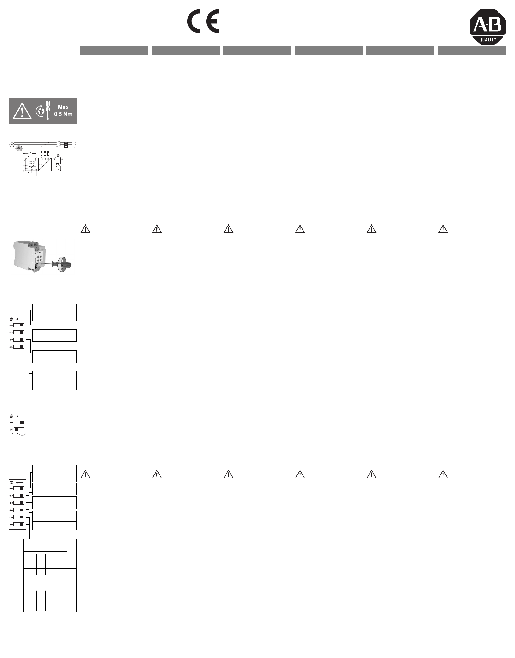
1 Connections
3-Phase voltage:
the 3-Phase power supply
to the terminals L1, L2 and
L3 taking care of the
sequence.
Current, direct: Connect
the current of the phase L1
(or L if 1-Phase) to the terminals I1 and I2.
Current, standard CT:
Connect the output current
from the standard CT to the
terminals I1 and I2.
Connect the relay output
according to the ratings.
Automatic screwdriver can
be used (max torque 0.5 Nm).
(
*) Suggested size for the
m
ains protection against
s
hort circuits on the termi-
Connect
nals blocks, in any case to
be coordinated with the
upstream protections.
1 Anschlüsse
3-Phasenspannung:
Schließen Sie die Betriebsspannung an die Klemmen
L1, L2 und L3 an; achten Sie
dabei auf die Phasenfolge.
Strom, direkt: Schließen
Sie die stromführenden
Leiter der Phase L1 (oder L
im 1-Phasennetz) an die
Klemmen I1 und I2 an.
Strom, Standardwandler:
Schließen Sie die Sekundärstromleitungen an die
Klemmen I1 und I2 an.
Schließen Sie den Relaisausgang entsprechend den
Betriebsdaten an.
Verwenden Sie dazu einen
automatischen Schraubendreher (Max. Drehmoment
0,5 Nm).
(*) Vorgeschlagene Sicherungsgröße für die wichtigsten Schutz gegen
Kurzschluss an den
Klemmen, muss mit dem
vorgelagerten Schutz koordiniert werden.
1 Raccordements
Tension triphasée:
Raccorder l'alimentation triphasée aux bornes L1, L2 ,
L3, en respectant la séquence indiquée.
Courant Continu:
Raccorder le courant de la
phase L1 (ou L si monophasé) aux bornes I1 et I2.
Transformateur Standard:
Raccorder la sortie courant
transformateur standard aux
bornes I1 et I2.
Raccorder le relais de sortie
selon les caractéristiques.
L'utilisation d'une visseuse
électrique est autorisé (serrage max 0,5 Nm).
(*) Dimensionnement de la
p
rotection principale contre
l
es courts-circuits, il doit
ê
tre en adéquation avec les
p
rotections principales de
l'installation.
Mounting and installation by skilled people only!
Montage und Installation nur durch Fachpersonal!
Montage et installation par des personnes habilitées seulement!
El montaje e instalación ha de realizarlo solo personal con experiencia!
Il montaggio e l’installazione va eseguito da parte di personale addestrato!
Montering og installation må kun foretages af faguddannede personer!
I
ESPAÑOL
1 Conexiones
Trifásica:
mentación trifásica a los terminales L1, L2 y L3, teniendo en cuenta la secuencia.
Intensidad, directa:
Conectar la intensidad de la
fase L1 (o L si es monofásica) a los terminales I1 e I2.
Intensidad, trafo estándar:
Conectar la salida de la
intensidad del trafo estándar a los terminales I1 e I2.
Conectar la salida de relé
según las escalas. Se puede
usar un destornillador automático (máx. par de apriete
0,5 Nm).
(*) Valor recomendado para
la protección de la red contra cortocircuitos en los bloq
ues de terminales, debe
c
oordinarse con las protec-
c
iones aguas arriba.
Conectar la ali-
1 Collegamenti
TALIANO
ensione trifase:
T
a tensione trifase di alimen-
l
tazione ai morsetti L1, L2 ed
L3 rispettando la sequenza.
Corrente, inserzione diretta: Collegare la corrente
della fase L1 (o L se si usa
un carico monofase) ai morsetti I1 ed I2.
Corrente, TA standard:
Collegare l’uscita del TA
standard ai morsetti I1 ed I2.
Collegare l'uscita relè
secondo i valori di carico
indicati. La coppia massima
in caso di uso di avvitatori
automatici è 0,5 Nm.
(*) Dimensionamento suggerito per evitare il cortocircuito sui morsetti, in ogni caso
deve essere coordinato con
la protezione a monte.
ollegare
C
1 Tilslutninger
3-faset spænding:
3-fasede forsyningsspænding til klemme L1, L2 og
L3. Rækkefølgen er meget
vigtig.
Strøm, standard-strømmåletransformator: Slut
udgangsstrømmen fra standard-strømmåletransformatoren til klemme I1 og I2.
Tilslut den relæstyrede
udgang i forhold til belastningen. Anvend evt. en
automatisk skruetrækker
(maks. tilspændingsmoment
0,5 Nm).
(*) Anbefalet størrelse for
beskyttelse mod kortslutninger på terminalerne
b
lokke, skal dimensioneres
s
åledes der er selektivitet
m
ed de forudgående
sikringer.
D
ANSK
Slut den
814S-PF3:
Input range (CT)
ON: 10 A
OFF:
ON: N.D.
OFF: N.E.
ON: Start/Stop
OFF: Latch/Inhibit
(SW3 OFF)
ON:
OFF: Inhibit
OFF
ON
814S-W3:
Input range (CT)
ON: 10 A
OFF:
ON: N.D.
OFF: N.E.
ON: Start/Stop
OFF: Latch/Inhibit
ON: Latch
OFF: Inhibit
(SW3 OFF)
Measuring voltage V
814S-W3-480V-10A:
ON
SW5
ON
SW6
380 400 415 480
814S-W3-690V
SW5 ON ON OFF OFF
SW6 ON OFF ON OFF
600 690 600 690
5A
Latch
5A
ON OFF OFF
OFF
ON
OFF
-10A:
Keep power OFF while
connecting!
2 Setting of function and
input range
Select the desired function
setting the DIP-switches 1
to 4 as shown on the left
column.
To access the DIP switches
open the grey plastic cover
as shown on the left.
SW1 selects the input current range: 10 A or 5A.
If the input current is
below 10% of the full scale
value the relay is conventionally in alarm condition.
SW2 selects the relay working mode: normally de-energized (relay energized in
alarm condition) or normally
energized (relay de-energized in alarm condition).
SW3 selects the contact
input working mode:
Start/Stop or Latch/Inhibit
function.
SW4 selects the contact
input function: latch or
inhibit of alarm enable. SW4
does not affect the working mode if SW3 is ON.
Do not open the DIP
switches cover if the
power supply is ON!
3 Contact input
Latch function (SW3 OFF
SW4 ON):
in the alarm condition if
ther
between the terminals Z1
and U1.
AC
Inhibit function (SW3 OFF
SW4 OFF): T
alarm status short cir
terminals Z1 and U1.
Start/stop function (SW3
ON): The device is active
when the terminals Z1 and
U1 ar
The r
e is no connection
o inhibit the
e connected.
elay latches
cuit the
Achten Sie beim
Anschluß auf
Spannungsfreiheit!
2 Einstellung von Funktion
und Eingangsbereich
Wählen Sie die gewünschte
Funktion mit den DIPSchaltern 1 bis 4, wie im linken Bild gezeigt. Öffnen Sie
die graue Kunststoffabdekkung wie im linken Bild
gezeigt, um die DIPSchalter einstellen zu können.
SW1: EingangsstromBereich einstellen: 10 A
oder 5 A.
Bei einem Eingangsstrom
kleiner als 1/10 des
Bereichsendwertes wird
eine Alarmmeldung gegeben.
SW2: Relaisstatus wählen:
In Ruhe nicht erregt (Relais
bei Alarmbedingung erregt)
oder in Ruhe erregt (Relais
bei Alarmbedingung nicht
erregt). SW3: Betriebsart
des Relais wählen: Start/Stop-Funktion oder
Funktion Selbsthalten/
Sperren. SW4: Funktion des
Kontakteingangs wählen:
Selbsthalten oder Sperren
des Alarms freigeben. Steht
SW3 3 auf EIN, hat SW4
keinen Einfluß auf die
Betriebsart.
Öffnen Sie die
Abdeckung der DIPSchalter nicht bei eingeschalteter Betriebsspannung!
3 Kontakteingang
Selbsthaltefunktion (SW3
,
AUS, SW4 EIN):
hält sich selbst bei einem
Alarm, wenn der Kontakt zwischen den Klemmen Z1 und
U1 geöffnet ist.
Sperrfunktion (SW3 AUS,
,
SW4 AUS): Um den Alarm
zu sperren, muß der Kontakt
zwischen den Klemmen Z1
und U1 geschlossen sein.
Start-/Stop-Funktion (SW3
EIN): Die Funktion ist aktiviert,
wenn der Kontakt zwischen den
Klemmen Z1 und U1 geschlossen ist.
Das Relais
Attention Danger: effectuer tous les raccordements Hors Tension!
2 Paramétrage de la fonc-
tion et réglage de la
gamme d'entrée
Sélectionner la fonction
souhaitée à l'aide des DIP
switch 1 à 4 , comme illustré
à gauche.
Pour accéder aux DIP
switch, ouvrir le capot en
e plastique grise,
matièr
comme illustré à gauche.
SW1 sélectionne la gamme
du courant d'entrée: 10 A ou
5A.
Si le courant d'entrée est
inférieur à 10 % de la
valeur en échelle totale, le
relais est par défaut en
mode alarme.
SW2 sélectionne le mode
de fonctionnement du
relais: normalement désactivé (relais actif en condition d'alarme) ou normalement désactivé (relais
inactif en condition d'alarme). SW3 sélectionne le
mode de fonctionnement
des contacts d'entrée:
Marche/Arrêt ou fonction
mémorisation/interdiction.
SW4 sélectionne la fonction
des contacts d'entrée:
mémorisation/interdiction
de l'activation de l'alarme.
SW4 n'affecte pas le mode
de fonctionnement si SW3
est ON.
Ne pas ouvrir le capot
des DIP switch lorsque
l'alimentation est active.
3 Entrée contact
Fonction mémoir
, SW4 ON):
OFF
mémorise en position d'a
larme s'il n'y a pas de con
nexion entr
et U1.
Fonction inter
, SW4 OFF):
OFF
e le fonctionnement de
dir
l'alarme, court cir
nes Z1 et U1 .
bor
Fonction démarrage/arrêt
(SW3 ON): l'appar
actif quand les bor
U1 sont raccor
Le r
e les bor
diction (SW3
Pour inter
cuiter les
nes Z1 et
dées.
e (SW3
elais
nes Z1
eil est
El equipo debe estar
desconectado mientras
se realizan las conexiones!
2 Ajuste de funciones y
rango de entrada
Seleccionar la función que
se desee con los interruptores DIP 1 al 4, como se indica a la izquierda. Para acceder a los interruptores DIP,
ender la tapa de plá
despr
stico gris como se indica.
SW1 selecciona la escala de
intensidad de la entrada: 10
ó 5 A.
Si la entrada de intensidad
está por debajo del 10%
del valor de la escala com
pleta, el r
cionalmente en condición
de alarma.
SW2 selecciona el modo de
trabajo del r
te desactivado (r
condición de alarma) o normalmente activado (relé
OFF en condición de alar
ma).
SW3 selecciona la entrada
de contacto del modo de
trabajo : Arranque/Parada o
función de Enclavar/Inhibir
SW4 selecciona la función
de contacto de la entrada:
alarma enclavada o inhibi
da.
de trabajo si SW3 está en
ON.
3 Entrada de contacto
Función de enclavamiento
(SW3·OFF, SW4 ON):
se enclava en condición de
alarma, si no hay conexión
entre los terminales Z1 y U1.
Función de inhibición (SW3
OFF, SW4 OFF): Para inhibir
el estado de alarma, corto-
circuitar los terminales Z1 y
U1.
Función de arranque/parada (SW3 ON): El equipo está
activado cuando están
conectados los terminales
Z1 y U1).
elé está conven-
elé: normalmen
elé ON en
SW4 no afecta al modo
No abra la cubierta de
los interruptor
está conectada la ali
mentación!
es DIP si
Staccare l'alimentazione prima di collegare lo
strumento!
2 Messa a punto della por-
tata d'ingresso e della funzione.
Impostare la funzione desiderata agendo sui DIP
switch da 1 a 4 come indi-
ato nella colonna di sini-
c
tra. Per accedere ai DIP
s
switch aprir
grigio usando un cacciavite
come mostrato in figura.
SW1 seleziona la gamma
della corr
10 A oppur
Se la corr
è sotto il 10% rispetto al
fondo scala impostato il
elè è per convenzione in
r
stato di allarme.
SW2 seleziona il modo di
funzionamento del r
malmente eccitato (r
eccitato in stato di allarme)
o normalmente diseccitato
elè eccitato in stato di
(r
allarme).
SW3 seleziona il modo di
funzionamento dell’ingr
di contatto: Start/Stop oppu
e Bloccaggio/Inibizione.
r
SW4 seleziona la funzione
esso di contatto:
dell’ingr
bloccaggio o inibizione del
funzionamento del r
SW4 non influenza il fun
zionamento se SW3 è ON.
Non aprir
DIP-switch se l'alimen
tazione è collegata!
-
esso di contatto
3 Ingr
Funzione di Latch (SW3
, SW4 ON):
El relé
OFF
ne bloccato in posizione di
allarme se non c’è collega
mento fra i morsetti Z1 e U1.
Funzione di Inibizione
(SW3 OFF, SW4 ON): Per
inibire lo stato di allarme
collegare i morsetti Z1 e U1.
Funzione Start/stop (SW3
ON): Lo strumento è attivo
quando i morsetti Z1 e U1.
e lo sportellino
ente di ingr
e 5 A.
ente di ingr
elè: nor
elè dis
e lo sportello
elè rima-
Il r
Strømmen skal være
SLUKKET under tilslutningen!
2 Indstilling af funktions- og
indgangsområde
Vælg den ønskede funktion
ved at indstille DIP-switch 1
og 4 som vist i venstre
kolonne.
Adgang til DIP-switches
opnås ved at åbne det grå
plastdæksel som vist til ven-
e.
str
esso:
esso
esso
Med SW1 vælges indgangs
strømområdet: 10 A eller
5A.
Hvis indgangsstrømmen
er under 10% af fuldskala
dien, står r
vær
malt i alarmtilstand.
Med SW2 vælges r
tionen: normalt deaktiver
-
elæ aktiver
(r
-
stand) eller normalt aktiver
elæ deaktiveret i alarmtil-
(r
stand).
Med SW3 vælges kontak
tindgangsdriftsfunktionen:
Start/stop- eller selvholde/
efunktion.
spærr
-
Med SW4 vælges kontak
tindgangsfunktionen: akti
vering af selvholdefunktion
eller alarmspærring.
påvirker ikke driftsfunktio-
elè.
nen, hvis SW3 er aktiveret.
-
Dækslet til DIP-switche-
-
ne må ikke åbnes, hvis
strømmen er tilsluttet!
3 Kontaktindgang
Selvholdefunktion (SW3
deaktiveret, SW4 aktiveret):
-
Relæet selvholder i
alarmtilstanden, hvis der
ikke er forbindelse mellem
klemme Z1 og U1.
Spærrefunktion (SW3
deaktiveret, SW4 deaktiveret): For at spærre alarmtil-
standen skal klemme Z1 og
U1 kortsluttes.
Start/stop-funktion (SW3
aktiveret): Enheden er aktiv,
når klemme Z1 og U1 er tilsluttet.
elæet nor-
elæfunk
et i alarmtil-
SW4
-
-
-
et
et
-
-
-
Bulletin 814S - 10000099363 (version 02) http://www.ab.com/en/epub/catalogs/12768/229240/229258/3170949/10357727/ 8021099
Page 2
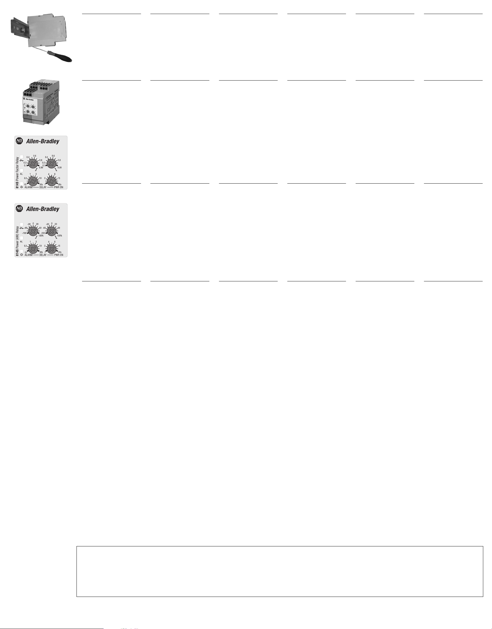
4 Mechanical mounting
Hang the device to the DINrail being sure that the
spring closes. Use a screwdriver to remove the product
as shown in figure.
5 Startup and adjustment
Check if the current input
range is correct. Turn the
power supply ON.
The green LED is ON.
Adjust the upper and lower
levels on the absolute scale
setting the left and right
centre knobs respectively.
Adjust the alarm and power
ON delay setting the right
and left lower knob.
See datasheet for the working mode explanation.
ontage
4 M
Hängen Sie das Relais in die
DIN-Schiene ein;
achten Sie darauf, daß die
Feder bei der Befestigung
einrastet. Verwenden Sie
einen Schraubendreher,
um das Relais wieder auszubauen, wie im nebenstehenden Bild gezeigt.
5
Einschalten und
Einstellungen
Prüfen Sie, ob der
Eingangsstrombereich richtig gewählt ist. Schalten Sie
die Betriebsspannung EIN.
Die grüne LED leuchtet.
Stellen Sie den oberen bzw.
unteren Grenzwert mit dem
linken bzw. rechten mittleren
Drehknopf auf der Skala ein.
Stellen Sie Alarmverzögerung
und Einschaltverzögerung
mit dem rechten und dem
linken unteren Drehknopf
ein.
Erklärung zur Arbeitsweise
siehe Datenblatt
4 Montage mécanique
Accrocher l'appareil au rail
DIN et s'assurer que le ressort se referme bien. Pour
déposer l'appareil, utiliser
un tournevis comme illustré
sur la figure.
5 Démarrage et réglage
Vérifier que la gamme du
courant d'entrée est correcte. Mettre l'alimentation
sous tension.
La LED verte s'allume.
Régler les niveaux supérieur
et inférieur sur l’échelle, en
agissant respectivement sur
les boutons gauche et droit.
Régler l'alarme et le temps
de mise sous tension en
agissant respectivement sur
les boutons gauche et droit.
Se référer à la fiche technique pour l'explication sur le
mode de fonctionnement.
4 Montaje mecánico
Colocar el equipo en el carril DIN, asegurándose que el
muelle cierra. Utilizar un
destornillador para
desprender el equipo como
se indica.
5 Puesta en marcha y ajuste
Comprobar que la escala de
entrada de intensidad es
correcta. Conectar el equipo.
El LED verde se ilumina.
Ajustar los niveles superior
e inferior sobra la escala
con los potenciómetros
superiores izquierdo y derecho respectivamente.
Ajustar la alarma y el retardo
de la alimentación con los
potenciómetros inferiores
derecho e izquierdo.
Véase su hoja de datos para
la explicación del modo de
operación
4 Montaggio sulla guida DIN
Agganciare lo strumento alla
guida DIN verificando la
chiusura della molla. Per
rimuovere il prodotto dalla
guida usare un cacciavite
come mostrato in figura.
5 Accensione e regolazione
Controllare che la gamma
della corrente di ingresso
sia corretta. Alimentare lo
strumento. Il LED verde si
accende.
Impostare le soglie minima e
massima sulla scala agendo sulle manopole centrali
di sinistra e destra rispettivamente.
Impostare il ritardo all’inserzione e all’avvio agendo
sulle manopole in basso di
destra e sinistra rispettivamente.
Vedere datasheet per il
modo di funzionamanto
4 Mekanisk montering
Når enheden monteres på
DIN-skinnen, skal det sikres,
at fjederen lukker. Brug en
skruetrækker til at fjerne
produktet som vist på illustrationen.
5 Opstart og justering
Kontrollér, at indgangsstrømområdet er korrekt. Tænd
for strømforsyningen.
Den grønne lysdiode er
TÆNDT.
Indstil værdierne for øvre og
nedre nivau på skalæn ved
at indstille midterste knap i
henholdsvis venstre og
højre side.
Juster alarm- og indkoblingsforsinkelsen ved at indstille
nederste knap i højre og
venstre side.
Se datablad for beskrivelse
af funktion.
814S-PF3
814S-W3
L1, L2, L3
L1, L2
I1, I2
Z1, U1
15, 16, 18
6
I
mportant
S
hould you require infor-
m
ation about installation,
o
peration or maintenance
of the product that is not
covered in this instruction
document, contact your
local Rockwell Automation
sales office or AllenBradley distributor. The
information in this docum
ent is not considered
b
inding on any product
f
amily.
erminals
7 T
3-Phase power supply
1-Phase power supply
(short cir
C
s
Latch/Inhibit (SW3 OFF) or
Start/Stop (SW3 ON) contact
Relay output
cuit L2, L3 or 6, 7)
urrent input (Dir
tandard CT)
ect or
6
Wichtig
S
ollten Sie Informationen
ü
ber Installation, Betriebs-
a
rten oder Wartung des
P
rodukts, die nicht in dieser Installationshinweise
abgedeckt sind, wenden
Sie sich zu Ihrem lokalen
Rockwell AutomationVertriebsbüro oder AllenBradley-Distributor. Die
Informationen in diesem
Dokument sind nicht verb
indlich für jedes Produkt
F
amilie.
7 Anschlußklemmen
Betriebsspannung
Drehstrom-Netz
Betriebsspannung
1-Phasennetz
(L2, L3 oder 6,7 überbrücken)
Stromeingang (Direkt oder
über Standardwandler)
Kontakt für Selbsthalten/
Sperren (SW3 AUS) oder
Start/Stop (SW3 EIN)
Relaisausgang
6
Important
Si vous désirez des informations sur l'installation,
fonctionnement ou la maintenance du produit qui ne
sont pas couvertes dans ce
d
ocument d'instructions,
v
euillez communiquer avec
v
otre bureau local Rockwell
A
utomation ou le distribu-
t
eur Allen-Bradley. Les
informations contenues
dans ce document ne sont
pas considérées comme
obligatoires pour toute la
famille de produits.
7 Bornes
Alimentation triphasée
Alimentation monophasée
(court circuit L2, L3 or 6, 7)
Courant d'entrée (Continu
ou TC standard)
Contact de mémorisation/
interdiction (SW3 désactivé)
ou démarrage/arrêt (SW3
activé) relais de sortie activé
Relais de sortie
6
Importante
S
i necesita informaciónes
s
obre la instalación, modo
de operación o mantenimiento del producto que no
estan cubiertas en este
documento de instrucciones, póngase en contacto
con su oficina local de ventas Rockwell Automation o
e
l distribuidor de AllenB
radley. Las informaciónes
c
ontenidas en este documento no se consideran
obligatorias para toda familia de productos.
7 Terminales
Alimentación trifásica
Alimentación monofásica
(cortocircuitar L2, L3 o 6 y 7)
Entrada de intensidad (directa o con trafo estándar)
Salida de relé de contacto:
Enclavar/Inhibir (SW3 OFF) o
Arranque/Parada (SW3 ON)
Salida de relé
6
Importante
Per informazioni su installazione, funzionamento o
manutenzione del prodotto
che non sono contemplate
n
el presente foglio istruzio-
n
i, contattare il locale uffi-
c
io commerciale Rockwell
Automation o il distributore
Allen-Bradley. Le informazioni contenute in questo
documento, per ogni famiglia di prodotti, non sono
considerate vincolanti.
7 Terminali di collegamento
Alimentazione trifase
Alimentazione monofase
(collegare L2 e L3 o 6 e 7)
Ingresso in corrente (Inserz.
diretta o TA standard)
Ingresso di Latch/Inibiz.
(SW3 OFF) o Start/Stop
(SW3 ON)
Uscita relè
6
Vigtigt
Skulle du kræve
oplysninger om installation,
funktionsbeskrivelse eller
vedligeholdelse af produkt
et, som ikke er omfattet af
d
enne instruktion doku-
m
ent, skal du kontakte dit
lokale Rockwell
Automation salgskontor
eller Allen-Bradley distributør. Oplysningerne i dette
dokument ikke betragtes
som bindende for ethvert
produkt familie.
7 Terminaler
3-faset forsyningsspænding
1-faset forsyningsspænding
(kortslut L2, L3 eller 6, 7)
Indgangsstrøm (dir
standar
sformator)
Selvholde/spærr
(SW3 deaktiver
start/stop-kontakt (SW3
aktiver
Relæstyret udgang
d-strømmåletran-
et)
ekte eller
e-kontakt
et) eller
Each terminal can accept up
to 2 x 2.5 mm
(30-14 A
2
es.
wir
WG, stranded or
solid).
Kelemmenanschluß bis max.
2 x 2,5 mm2je Klemme.
(30-14 AWG, flexibel oder
starr).
Chaque borne accepte jusqu'à deux conducteurs de
2
2,5 mm
.
(30-14 AWG, bloqué ou
solide).
Cada terminal acepta cables
de hasta 2 x 2,5 mm2.
(30-14 AWG, varados o sólidos).
Ad ogni morsetto possono
essere collegati 2 fili di
2
2,5 mm
.
(30-14 AWG, flessibile o rigido).
Hver klemme er klassificeret til
ledninger på op til 2 x 2,5mm2.
(30-14 AWG, strandede eller
fast).
“UL notes”
For Canadian application, these devices shall be supplied by a secondary circuit, which is not directly derived from the primary circuit and where the short-circuit limit between conductors or
•
between conductors and gr
consideration shall be evaluated in the final use.
“Use 60 or 75°C copper (CU) conductor and wire size No. 30-14 AWG, stranded or solid”.
•
• “Terminal tightening torque of 4.4 Lb-In”.
• Being these devices Overvoltage Category III they are: "For use in a circuit where devices or system, including filters or air gaps, are used to control overvoltages at the maximum rated
impulse withstand voltage peak of 6 .0 kV. Devices or system shall be evaluated using the requirements in the Standard for Transient Voltage Surge Suppressors, UL 1449 and shall also withstand the available short circuit current in accordance with UL 1449".
ound is 1500 VA or less: the short-circuit volt ampere limit is the product of the open circuit voltage and the short circuit ampere. For other applications additional
Bulletin 814S - 10000099363 (version 02) http://www.ab.com/en/epub/catalogs/12768/229240/229258/3170949/10357727/ 8021099
 Loading...