

Page 1
Bulletin 813S
Voltage Relay
Single Phase
813S-V1-500V-48
813S-V1-500V-230
F
F
F=250mA (*)
AC/DC voltage monitoring relay
AC/DC Spannungsüberwachungsrelais
Relais de contrôle de tension CA/CC
Relé de control de tensión CA/CC
Relè di tensione CA/CC
A
C/DC spændingsmålerelæ
ENGLISH DEUTSCH
1
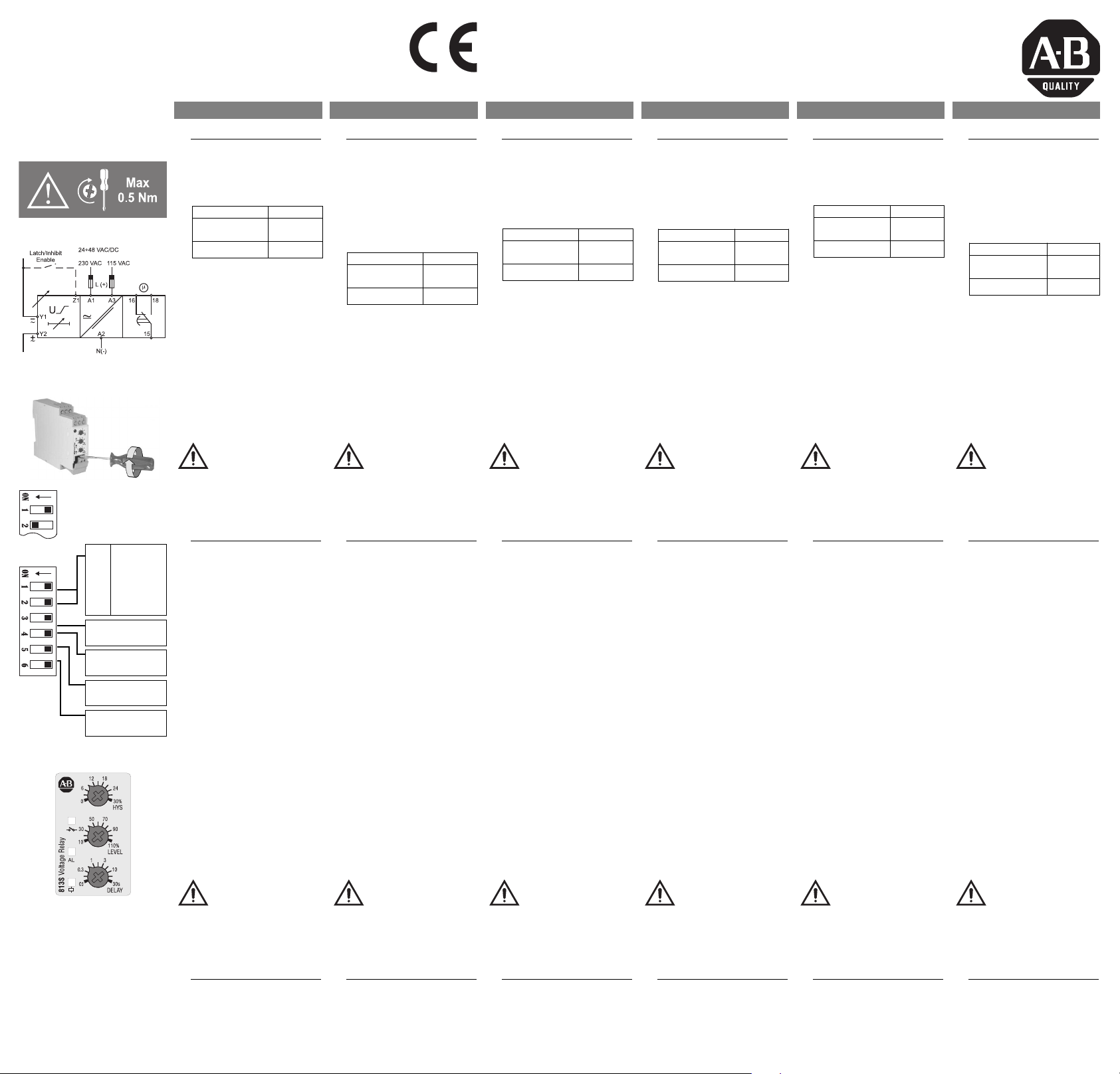
Connections
Connect the power supply
to the proper terminals, Y1
and Y2 to the measured
v
oltage (taking care of
p
olarity if DC).
Power supply Terminals
24÷48 VAC/DC
230 VAC
115 VAC A3, A2
Connect the relay output
according to the ratings.
Automatic screwdriver can
be used (max torque 0.5
N
m).
(*) Suggested size for the
mains protection against
short circuits on the terminals blocks, in any case to
be coordinated with the
upstream protections.
A1, A2
1
Anschlüsse
Betriebsspannung an die
dafür vorgesehenen
Klemmen anschließen.
M
eßeingang Y1 und Y2
(
achten Sie bei DC auf die
r
ichtige Polarität) und den
Relaisausgang entsprechend den Betriebsdaten
anschließen.
Betriebspann. Klemmen
24÷48 VAC/DC
A
utomatische Schrauben-zieher können benutzt werden
(Drehmoment max. 0,5 Nm).
(*) Vorgeschlagene Sicherungsgröße für die wichtigsten Schutz gegen
Kurzschluss an den
Klemmen, muss mit dem
vorgelagerten Schutz koordiniert werden.
230 VAC
115 VAC A3, A2
A1, A2
Installation instructions
Installationshinweise
Notice d’installation
Instrucciones de instalación
Istruzioni per l’installazione
I
nstallationsvejledning
FRANÇAIS
1
Connections
Raccorder l’alimentation
sur les bornes réservées à
cet effet. Raccorder l’ent
rée tension sur les bornes
Y
1 et Y2 (respecter le sens
d
e polarité en version con-
tinue).
Alimentations Bornes
24÷48 VCA/CC
230 VCA
115 VCC A3, A2
Raccorder le relais de sortie en respectant la charge
a
dmissible. Une visseuse
électrique peut être utilisée
(couple maximum 0,5 Nm).
(*) Dimensionnement de la
protection principale contre
les courts-circuits, il doit
être en adéquation avec les
protections principales de
l'installation.
A1, A2
Mounting and installation by skilled people only!
Montage und Installation nur durch Fachpersonal!
Montage et installation par des personnes habilitées seulement!
El montaje e instalación ha de realizarlo solo personal con experiencia!
Il montaggio e l’installazione va eseguito da parte di personale addestrato!
M
ontering og installation må kun foretages af faguddannede personer!
ESPAÑOL
1
Conexiones
Conectar la alimentación a
los bornes correspondientes, la tensión a medir a Y1
e
Y2 (tener en cuenta la
p
olaridad si es CC) y el relé
d
e salida de acuerdo a la
carga indicada.
Alimentación Terminales
24÷48 VCA/CC
230 VCA
115 VCA A3, A2
Puede usarse un destornillador automático (max. par
0
.5 Nm).
(*) Valor recomendado para
la protección de la red contra cortocircuitos en los
bloques de terminales,
debe coordinarse con las
protecciones aguas arriba.
A1, A2
ITALIANO DANSK
1
Collegamenti
Collegare l’alimentazione ai
rispettivi morsetti, Y1 e Y2
alla tensione misurata
(
rispettando la polarità se
C
C).
Alimentazione Terminali
24÷48 VCA/CC
230 VCA
115 VCC A3, A2
Collegare l’uscita relè
secondo i valori di carico
indicati. La coppia massima in caso di uso di avvitat
ori automatici è 0.5 Nm
(*) Dimensionamento suggerito per evitare il cortocircuito sui morsetti, in ogni
caso deve essere coordinato con la protezione a
monte.
A1, A2
1
Tilslutninger
Tilslut forsyningsspændingen til de rigtige terminaler. Tilslut målespænd
ingen til Y1 og Y2 (husk
k
orrekt polaritet ved DC).
T
ilslut relæudgangen i
overensstemmelse med
data.
Spændingsfors.
24÷48 VAC/DC
230 VAC
115 VAC A3, A2
Automatskruetrækker kan
a
nvendes (max. moment
0,5 Nm).
(*) Anbefalet størrelse for
beskyttelse mod kortslutninger på terminalerne
blokke, skal dimensioneres
således der er selektivitet
med de forudgående
sikringer.
Terminals
A1, A2
OFF
ON
SW1 SW2
ON OFF: 20 V
OFF: 50 V
OFF
ON ON: 200 V
OFF ON: 500 V
ON: N.D.
OFF: N.E.
0.5 s
±
ON: 6
OFF: 1 ± 0.5 s
ON: LATCH
OFF: INHIBIT
ON: OVER
OFF: UNDER
Keep power OFF
while connecting!
2
Setting of function and
input range
Adjust the input range set
ting the DIP switches 1 and
2. Select the desired function setting the DIP switches 3 to 6. To access the DIP
switches open the plastic
cover using a scr
as shown on the left.
SW3 selects the status of
the relay: normally energized (relay OFF in alarm
condition) or normally deenergized (relay ON in
alarm condition). SW4
selects the power-ON
delay (inhibit of the alarm at
the power-ON): 1s or 6s.
SW5 selects the contact
input function: latch or
inhibit of alarm enable.
SW6 selects the function:
under or overvoltage.
ewdriver
Achten Sie während
dem Anschließen auf
Spannungsfreiheit!
2
Wahl der Funktion und
des Eingangsbereichs
-
Um Zugang zu den DIP-
n zu bekommen, muß
Schalter
die Klappe mit Hilfe eines
Schraubenziehers - wie in der
Illustration gezeigt - geöffnet
den. Den gewünschten
wer
Ein-gangsber
Schaltern SW1 und SW2 einstellen.
Die Funktion über die DIPSchalter SW3 bis SW6 auswählen. Mit SW3 wird die
Schaltart des Relais definiert:
"normal deaktiviert" (das Relais
zieht im Alarmfall an) oder "normal aktiviert" (das Relais fällt im
Alarmfall ab). Mit SW4 wird die
Meßverzögerung nach dem
Anlegen der Betriebs-spannung eingestellt: 1s oder 6s.
SW5 definiert die Funktion des
Kontaktein-gangs:
Selbsthaltung oder
Alarmsperre. Mit SW6 wird die
Überwachungsfunktion
bestimmt: Über- oder
Unterspannung.
eich mit den DIP-
Couper l’alimentation lors des raccordements!
2
Paramétrage de la fonction et de la gamme de
mesure
Ajuster la gamme de mesu
re en paramétrant les micr
commutateurs 3 à 6. Pour
accéder au micro commutateurs ouvrir le cache
plastique en utilisant un
nevis tel indiqué sur la
tour
gauche.
SW3 sélectionne l’état du
relais: normalement activé
(relais désactivé en position
alarme). SW4 sélectionne le
temps d’alimentation (inhibition de l’alarme lors de la
mise sous tension): 1s ou
6s. SW5 sélectionne la
fonction du signal d’entrée:
verrouillage ou inhibition de
l’activation de l’alarme.
SW6 sélectionne la fonction: mini ou maxi de tension.
Desconecte la alimentación antes de
realizar las conexiones!
2
Ajuste del rango de
entrada y de la función
-
Seleccionar la entrada de
o
tensión deseada a través
de los interruptores DIP 1 y
2, y la función a través de
los interruptores DIP 3, 4,
5, y 6. Para acceder a los
interruptor
tapa de plástico como indica la figura de la izquierda.
SW3 selecciona el estado
del relé: normalmente excitado o normalmente desexcitado. SW4 selecciona el
retardo a la conexión
(Inhibe el disparo durante la
conexión del relé) 1s o 6s.
SW5 selecciona la función
del contacto exterior: Relé
de salida enclavado o inhibido. SW6 selecciona la
función:máxima o mínima
tensión.
es DIP abrir la
Staccare l’alimentazione prima di collegare lo strumento!
2
Messa a punto della portata d’ingresso e della
funzione
Selezionar
derata attraverso i DIP
switch 1 e 2. Selezionare la
funzione attraverso i DIP
switch da 3 a 6. Per acceder
sportellino usando un cac
ciavite come mostrato in
figura.
SW3 seleziona lo stato del
relè: normalmente eccitato
(relè spento in stato di allarme) o normalmente diseccitato (relè acceso in stato
di allarme). SW4 seleziona
il ritardo all’avvio (inibizione
del funzionamento del relè
all’avvio): 1s o 6s. SW5
seleziona la funzione dell’ingresso di contatto: bloccaggio o inibizione del funzionamento del relè. SW6
seleziona la funzione: sovra
o sottotensione.
e la portata desi-
e ai DIP switch aprire lo
Forsyningen skal
være koblet fra,
mens forbindelserne
etableres!
2
Indstilling af funktionsog indgangsområde.
Indstil indgangsområdet
med DIP-switch 1 og 2.
Vælg det ønskede funktionsområde med DIP-swich'ene 3 til 6. For at få
adgang til DIP-swich'ene
-
åbnes plastikdækslet med
en skruetrækker som vist til
venstre.
SW3 vælger relæets status:
Normal aktiveret (relæ OFF
i alarmsituation) eller normal uaktiveret (relæ ON i
alarmsituation). SW4 vælger opstartsforsinkelse
(undertrykkelse af alarm
ved tilslutning af forsyningsspænding): 1 sek.
eller 6 sek. SW5 vælger
funktionen af kontaktindgangen: Selvhold eller
undertrykkelse af alarmfunktion. SW6 vælger funktionen: Over- eller underspænding.
Do not open the
DIP-switches cover
if the Power Supply
is ON
3
Latch/Inhibit control
input
o latch or inhibit the alarm
T
short cir
Z1 and Y1.
cuit the terminals
Bulletin 813S - 10000099360 (version 02)
Achtung! Gerät vor
dem Öffnen der DIPSchalterabdeckung
spannungsfrei schalten.
3
Selbsthaltung/Alarmsperre
(Kontakteingang)
Für die Selbsthaltung oder die
Alarmsperr
SW5) brücken Sie die
Klemmen Z1 und Y1 .
http://www
e (DIP-Schalter
.ab.com/en/epub/catalogs/12768/229240/229258/3170949/10357727/ 8021097
Ne pas ouvrir le
convercle des micro
commutateurs si
l’appareil est sous
tension.
3
Verrouillage/inhibition du
signal d’entrée
Pour verr
l’alarme court-cir
bor
ouiller ou inhiber
cuiter les
nes Z1 et Y1.
No abrir la tapa de
los interruptores
DIP bajo tensión de
alimentación
3
Entrada de control de
Latch e Inhibición
Enclavar la alarma conec
tando las bor
nas Z1 e Y1 .
Non aprire lo sportello DIP-switch se
l’alimentazione è
collegata!
3
Ingresso di contatto lach
e inhibit
-
Per bloccar
allarme collegar
Z1 e Y1.
e lo stato di
e i terminali
Beskyttelsesdæksle
t over DIP-switches
må ikke fjernes, når
forsyningsspændingen er tilsluttet
3
Selvhold/undertrykkelse
kontaktindgang
Selvhold eller undertrykkelse
af alarm ved kortslutning af
terminaler
ne Z1 og Y1.
Page 2
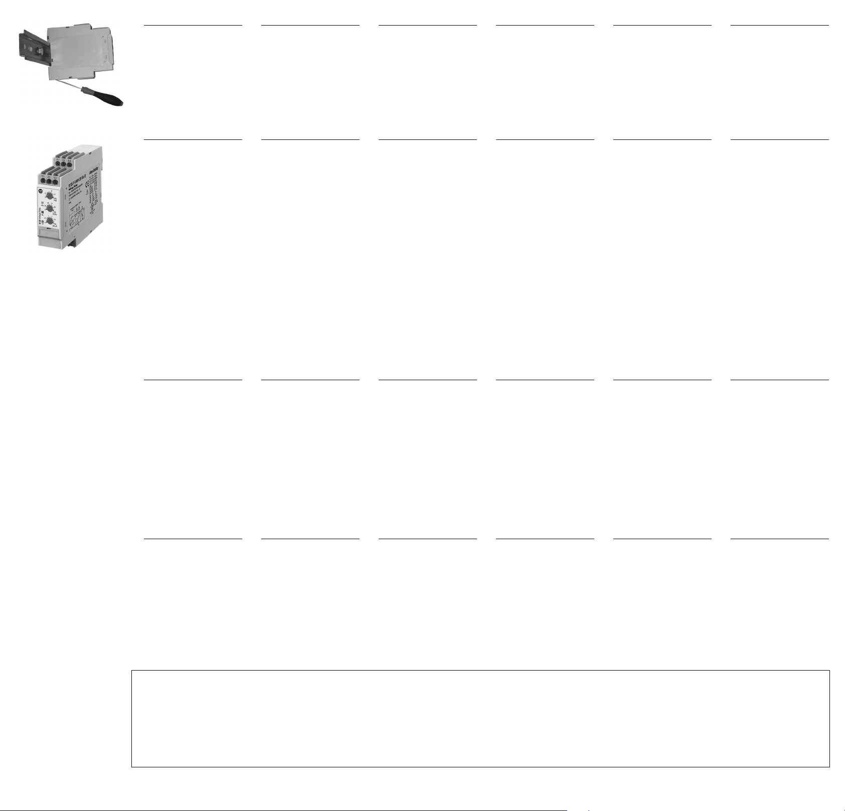
4
M
echanical mounting
H
ang the device to the
D
IN-Rail being sure that the
spring closes. Use a screwdriver to remove the product as shown in figure.
5
Startup and adjustment
Check if the input range is
correct. Turn the power
ON. The green LED is ON.
A
djust the level, delay and
h
ysteresis (difference
b
etween the alarm ON and
the alarm OFF thresholds)
knobs to the desired value.
When the voltage exceeds
(or drops below) the set
point for more than the set
delay time, red LED (flashing during the delay time)
turns ON. Relay and yellow
LED turn ON if the relay is
normally de-energized,
they turn OFF if normally
energized.
4
M
ontage
B
efestigen Sie das Relais
a
uf der DIN-Schiene und
achten Sie darauf, daß die
Befestigungsfeder eingerastet ist. Benutzen Sie einen
Schraubenzieher, wie im
nebenstehenden Bild
gezeigt, um das Relais wieder zu entfernen.
5
Einschalten und
Einstellungen
Betriebsspannung kontrollieren und einschalten - die
grüne LED leuchtet. Stellen
S
ie an den Drehknöpfen den
g
ewünschten Grenzwert,
d
ie Hysterese und die
Alarmverzögerung ein.
Wenn die Meßspannung
den eingestellten Grenzwert
länger als die vorgewählte
Verzögerungszeit über-,
beziehungsweise unterschreitet (Auswahl über DIPSchalter SW6), schaltet der
Ausgang und die rote LED
leuchtet (blinkt während der
Verzögerung). Das Relais
zieht an und die gelbe LED
leuchtet, wenn mit DIPSchalter SW3 als "normal
deaktiviert" definiert. Bei
"normal aktiviert" fällt das
Relais ab und die gelbe LED
verlöscht.
4
M
ontage mécanique
A
ccrocher l’appareil sur le
r
ail DIN en s’assurant que
l’agrafe est positionnée.
Utiliser un tournevis pour le
retirer tel indiqué sur le
schéma.
5
Mise en service et réglage
Vérifier si la gamme de
mesure est correcte. Mettre
sous tension. La LED verte
e
st allumée. Ajuster la
v
aleur, le temps et l’hysté-
r
ésis (différence entre le
seuil d’alarme activé et
désactivé) à l’aide du
potentiomètre à la valeur
désirée. Quand la tension
excède (ou chute au-dessous) du seuil au-delà du
temps programmé, la LED
rouge s’allume (clignotement pendant la durée). Le
relais et la LED jaune sont
activés si le relais est normalement désactivé, ils
sont désactivés si normalement activés.
4
M
ontaje Mecánico
S
ujetar el equipo al rail DIN
a
segurando que las bridas
de sujección esten cerradas. Use un destornillador
para manipular el equipo
como indica la figura.
5
Ajuste y puesta en marcha
Chequear que el rango de
entrada es correcto.
Alimentar el equipo, el LED
v
erde se enciende, ajustar
l
os potenciometros fronta-
l
es al valor deseado de tensión, histéresis y tiempo de
retardo. Cuando la tensión
sea superior (o inferior) al
valor ajustado, el LED rojo
parpadeará durante el tiempo de retardo y se pone a
ON. El relé de salida y el
LED amarillo se ponen a
ON si el relé esta normalmente desexcitado y se
ponen a OFF si el relé esta
normalmente excitado.
4
M
ontaggio sulla guida DIN
A
gganciare lo strumento
a
lla guida DIN verificando
la chiusura della molla. Per
rimuovere il prodotto dalla
guida usare un cacciavite
come mostrato in figura.
5
Accensione e regolazione
Controllare la correttezza
della portata. Alimentare lo
strumento. Il LED verde si
a
ccende. Regolare le
m
anopole di livello, isteresi
(
differenza fra la soglia di
intervento e quella di disinserzione dell’allarme) e
ritardo al valore desiderato.
Quando la tensione supera
(o scende al di sotto) del
valore impostato per più
del tempo di ritardo il LED
rosso (che lampeggia
durante il tempo di ritardo)
si accende. Il relè e il LED
giallo si accendono se il
relè è normalmente diseccitato, si spengono se è
normalmente eccitato.
4
M
ekanisk montering
M
onter systemet på DIN-
s
kinnen, og sørg for, at fjederen låser. Afmontering af
systemet foretages ved at
anvende en skruetrækker
som vist i figuren.
5
Opstart og justering
Kontroller, at indgangsområdet er korrekt. Tilslut forsyningsspændingen. Den
g
rønne lysdiode tændes.
I
ndstil knapperne for
n
iveau, forsinkelse og hysterese (forskellen imellem
punkterne, hvor alarm er
aktiveret og ikke aktiveret)
til den ønskede værdi.
Stiger indgangsspændingen over (eller falder under)
den indstillede værdi i
længere tid end tidsforsinkelsen, vil den røde lysdiode (blinker under tidsforsinkelsen) aktiveres. Relæet
og den gule lysdiode aktiveres, hvis relæet normalt
er afbrudt, de afbrydes,
hvis de normalt er aktiveret.
A1, A2, A3
Y1, Y2
Y1, Z1
15, 16, 18
6
Important
Should you require information about installation,
operation or maintenance
of the product that is not
covered in this instruction
document, contact your
local Rockwell Automation
sales office or AllenBradley distributor. The
information in this document is not considered
binding on any product
family.
7
Terminals
Power supply
Voltage input
Latch/Inhibit input
Relay output
Each terminal can accept
up to 2 x 2.5 mm
2
wires.
(30-14 AWG, stranded or
solid).
6
Wichtig
Sollten Sie Informationen
über Installation, Betriebsarten oder W
artung des
Produkts, die nicht in dieser Installationshinweise
abgedeckt sind, wenden
Sie sich zu Ihrem lokalen
Rockwell AutomationVertriebsbüro oder AllenBradley-Distributor. Die
Informationen in diesem
Dokument sind nicht verbindlich für jedes Produkt
Familie.
7
Anschlußklemmen
Betriebsspannung
Eingang Meßspannung
Selbsthaltung/Alarmsperre
Relaisausgang
Klemmenanschluß bis max.
2 x 2,5 mm
2
je Klemme.
(30-14 AWG, flexibel oder
starr).
6
Important
Si vous désirez des informations sur l'installation,
fonctionnement ou la main
tenance du produit qui ne
sont pas couvertes dans ce
document d'instructions,
veuillez communiquer avec
votre bureau local Rockwell
Automation ou le distributeur Allen-Bradley. Les
informations contenues
dans ce document ne sont
pas considérées comme
obligatoires pour toute la
famille de produits.
7
Borniers
Alimentation
Entée tension
Entrée Verrouillage/inhibition
Sortie relais
Chaque borne peut accepter des câbles 2 x 2,5 mm
(30-14 AWG, bloqué ou
solide).
6
Importante
Si necesita informaciónes
e la instalación, modo
sobr
-
de operación o manteni
miento del producto que no
estan cubiertas en este
documento de instrucciones, póngase en contacto
con su oficina local de ventas Rockwell Automation o
el distribuidor de AllenBradley. Las informaciónes
contenidas en este documento no se consideran
obligatorias para toda familia de productos.
7
Terminales
Alimentación
Entrada de tensión
Entrada de Latch/Inhibición
Relé de salida
Cada terminal admite 2
2
.
cables de 2,5 mm
(30-14 AWG, varados o
sólidos).
6
Importante
Per informazioni su installazione, funzionamento o
-
manutenzione del pr
che non sono contemplate
nel presente foglio istruzioni, contattare il locale ufficio commerciale Rockwell
Automation o il distributore
Allen-Bradley. Le informazioni contenute in questo
documento, per ogni famiglia di prodotti, non sono
considerate vincolanti.
odotto
6
Vigtigt
Skulle du kræve oplysninger om installation, funk
tionsbeskrivelse eller vedli
geholdelse af produktet,
som ikke er omfattet af
denne instruktion dokument, skal du kontakte dit
lokale Rockwell
Automation salgskontor
eller Allen-Bradley distributør. Oplysningerne i dette
dokument ikke betragtes
som bindende for ethvert
-
-
produkt familie.
7
Terminali di collegamento
Alimentazione
Ingresso di tensione
Ingresso di contatto
Uscita relè
2
.
Ad ogni morsetto possono
essere collegati 2 fili di
2
.
2,5 mm
(30-14 AWG, flessibile o
7
Terminaler
Spændingsforsyning
Spændingsindgang
Selvhold/undertrykkelse
Relæudgang
Hver terminal kan acceptere kabel op til 2 x 2,5 mm
(30-14 AWG, strandede
eller fast).
2
.
rigido).
“UL notes”
For Canadian application, these devices shall be supplied by a secondary cir
•
between conductors and gr
consideration shall be evaluated in the final use.
“Use 60 or 75°C copper (CU) conductor and wire size No. 30-14 AWG, stranded or solid”.
•
“Terminal tightening torque of 4.4 Lb-In”.
•
Being these devices Overvoltage Category III they are: "For use in a circuit where devices or system, including filters or air gaps, are used to control overvoltages at the maximum rated impulse
•
withstand voltage peak of 6.0 kV
available short cir
Bulletin 813S - 10000099360 (version 02)
ound is 1500 V
. Devices or system shall be evaluated using the requirements in the Standard for Transient Voltage Surge Suppressors, UL 1449 and shall also withstand the
cuit current in accordance with UL 1449".
http://www
A or less: the short-circuit volt ampere limit is the product of the open circuit voltage and the short circuit ampere. For other applications additional
.ab.com/en/epub/catalogs/12768/229240/229258/3170949/10357727/ 8021097
cuit, which is not directly derived from the primary circuit and where the short-circuit limit between conductors or
 Loading...