

Page 1
INSTRUCTIONS
INVERSE TIME CURRENT RELAYS
BULLETIN
810
I
IMPORTANT - Save for future
reference.
I
Bulletin 810
with a maximu
continuous
of 60 amperes.
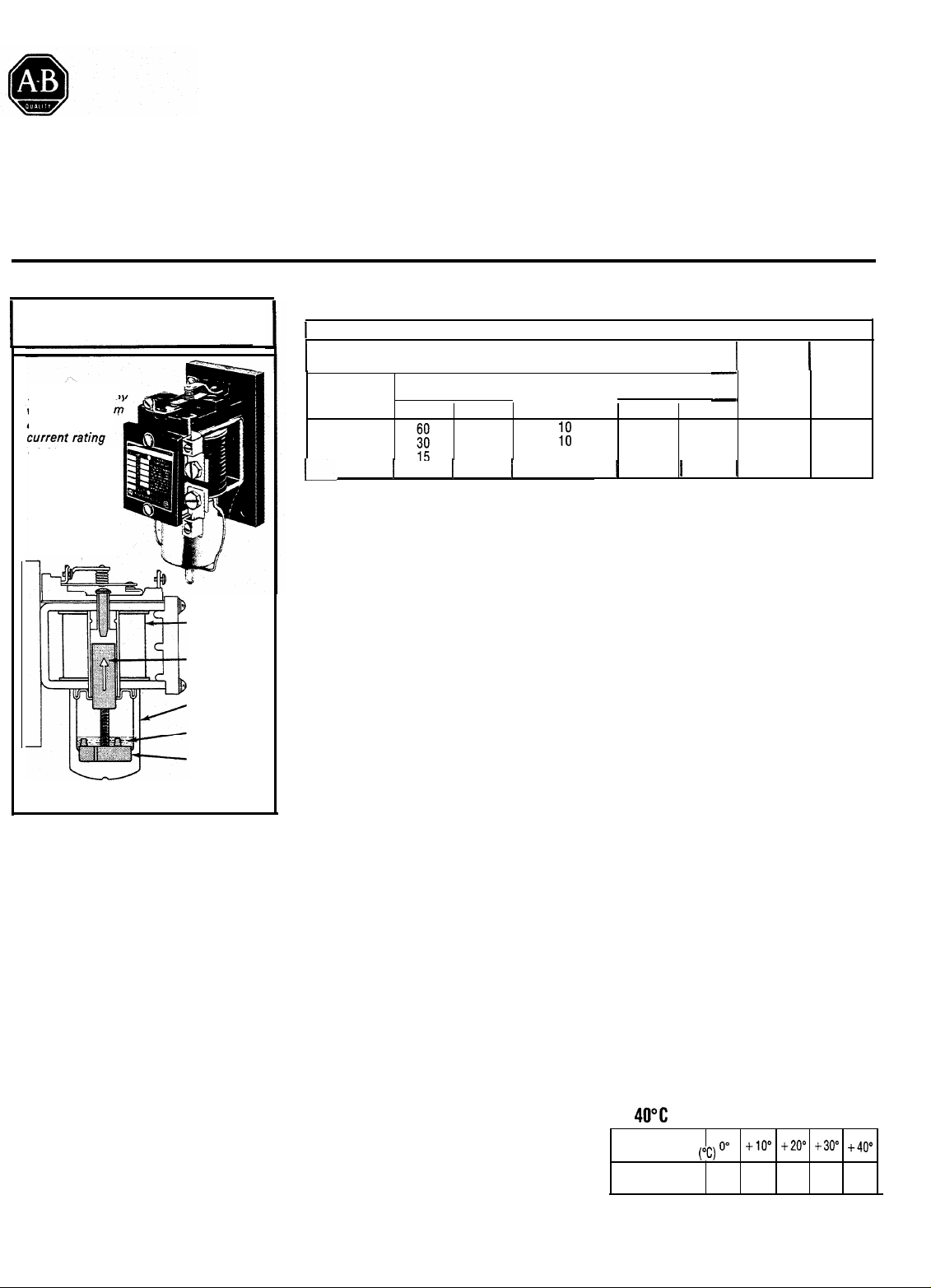
Cross sectional view.
Moving parts are shaded.
DESCRIPTION
rela
OPERATING
COIL
CORE
DASHPOT
SILICONE
FLUID
PISTON
-The Bulletin 810 is a
magnetically operated current relay,
with time delay, for use on AC or DC
applications. It has inverse time-current
characteristics which are dependent.
upon the viscosity of the fluid in the
dashpot. However, unlike thermal relays, minimum operating current is independent of ambient temperature change
or cumulative heating. The relays are
supplied as standard with
a normally
closed (NC) contact and an automatic
reset. Available options are a normally
open (NO) contact, hand reset, and
bifurcated contacts with a clear plastic
(poly-carbonate) cover. Tripping current
and time delay are adjustable.
TIME DELAY TRIP - Current relays are
used when it is desirable to take a motor
off the line in a certain period of time after
a predetermined load condition is
reached. A typical application would be
starting a large motor, where the Bulletin
810 is used to automatically open the
motor starter control circuit if the motor is
CONTACT RATINGS -
I
Max AC
Voltage
60 or 50
120
240
480 1.5 10
600 1 12 1 1.2
not up to speed in the maximum acceleration time allowed. In this and other
applications of the automatic reset type
relay, three wire control must be used,
with a provision for interrupting the cur-
rent through the relay coil immediately
after the relay trips (see typical schema-
tic diagram on page 3). On two wire con-
trol applications such as float switches,
pressure switches or thermostats, a
hand reset type overload relay must be
used to provide this protection to the coil.
The relay can carry its rated continuous
current in the non-tripped position only.
OPERATION -
letin 810 operating coil imparts an electromagnetic force on the movable core.
The vertical position of the core in the
coil is adjustable, thereby providing an
adjustable trip point. When the coil cur-
rent increases to the trip point, the core
raises to operate the contact mecha-
nism. Time delay is provided by a sili-
cone fluid dashpot mounted below the
core and coil assembly. An adjustable
valve in the dashpot piston provides for
time delay adjustment.
AC DC
Maximum Contact Rating Per Pole
NEMA Rating Designation A600
Continuous
Range
Amperes
Hz
Make Break
Carrying
Current
6
3
1;
1
10
Current through the Bul-
NORMAL CURRENT - The electro-
magnetic force caused by normal continuous current through the operating
coil is not great enough to lift the core
and piston. The relay remains
inoperative.
OVERCURRENT- When the current
through the operating coil increases
beyond the trip point, the resultant elec-
tromagnetic force causes the core and
piston to raise. Upward motion is dampened through the use of the silicone fluid
dashpot The core rises slowly until the
I
I
-
Voltage
Volt-amperes
Make
Break
7200 720 115-125
7200 720 230-250
7200 720 550-600 0.1
1
7200 1 720
1
Ampere
Rating
00.4
0.2
I
piston reaches an increased diameter in
the dashpot, where it is free, to trip the
contact with a quick action. Time and
current required to complete this cycle
are inversely related as shown by the
time-current characteristics curves on
page 2.
RESET - Standard models of the Bulle-
tin 810 are automatically reset as soon
as the current through the coil is interrupted or decreased to approximately
20% of the tripping current. The core is
designed to drop quickly, returning the
contacts to their normal position. A
check valve allows the piston to bypass
the fluid in its return to the bottom of the
dashpot. The action of hand reset models differs only in that the contacts do not
reset until a lever on the contact block is
operated. There is no waiting period as
with thermal relays.
EFFECTS OF AMBIENT TEMPERATURE
-
The minimum operating current
(100% on the time-current characteristics graph) is independent of ambient
temperature at the relay. However, the
operating time at overcurrent varies
directly to the viscosity of the silicone
fluid. Since the viscosity varies inversely
with ambient temperature, the operating
time is also inversely affected. The time
temperature table shows the correction
factors to be applied to the operating
times for various temperatures.
TIME TEMPERATURE RELATIONSHIP
( +
40°C
Reference)
Ambient
Temperature
Operating Time
Correction Factor
Supersedes Publication 810-5.0, Dated December, 1980
(“C)
2.25 1.80 1.45 1.20 1.0
Publication 810-5.0 - April, 1983
-
+lO"
‘”
+20" +30" +40"
Page 2
OPERATING CURRENT ADJUSTMENT - stamped on the nameplate. After the
(Not necessary if factory set to user’s
specified value). The minimum operat-
ing current (100% on the time-current
characteristics graph) is adjusted by
changing the vertical position of the core
within the operating coil. Calibration
lines on the core correspond to current
values in the table on Page 3 and
core and dashpot assembly is removed,
the core is turned up or down on the
piston’s threaded stem till the line cor responding to the desired operating cur-
rent is in line with the top edge of the
dashpot Currents other than those indi-
cated by the lines are possible by
interpolation.
NOTE: If electrical tests are made of cur-
rent calibrations they should be done
without fluid in the dashpot (clean
and dry.)
SERIES B RELAY OR SERIES B DASHPOTO SERIES A RELAY OR SERIES A DASHPOT 0
ARACTERISTIC AT
+4R"C
000 ’
8001
I
i
0.1 ;
100 200 300 400 500 600
Percent of Minimum Operating Current
10000
TlME-CURRENTCHARACTERlSTICSAT+4O"C
Ez
4000
I I I
I I I I
I I I I
'
I I
I
1
0.1 '
'
0 100
Percen
t
of Minimum Operating Current
I I I
'
200 300 400 500
I
600
I
With Series B FluidWith Series B Fluid
Red Fluid
\
.
t
i
0.2
,>I
0.1 '
0 100 200 300 400 500 600
Percent of Minimum Operating Current
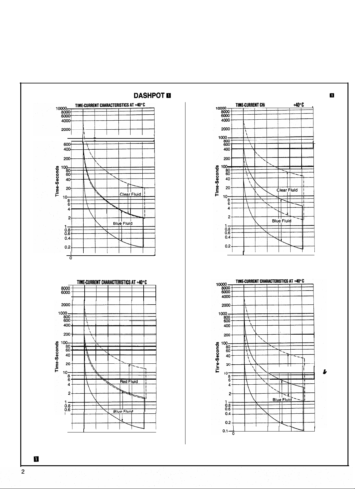
0 Series B Dashpots are identified by the rib along the side of the dashpot. Refer to photo on back page. Series A Dashpots do not have this rib.
1
b-ii
I
I
'
I
I I
With Series A Fluid
I
'
100 200 300 400 500 600
Percent of Minimum Operating Current
With Series A Fluid
i
Page 3

ADDING DASHPOT FLUID - (See note
Page 2) The dashpot fluid is shipped
separately. To add fluid, remove the core
and
dashpot
assembly by unfastening
the spring clamp. Remove the dashpot
cover by pulling the core straight out of
the dashpot Remove and discard red
plastic shipping spacer if present. Add
the silicone fluid with the dashpot cover
removed, with the piston and core in
place. Fill the dashpot to the top of the
three round projections on the piston.
See illustration below. The fluid must be
free of dirt or grit, and the dashpot and
piston must be absolutely clean.
Check fluid level periodically,
OPERATING TIME ADJUSTMENT - Un-
less ordered with a specified time delay
setting, the relays are set for minimum
time delay when shipped. To increase
the time delay, remove the piston from
the dashpot and decrease the opening
of the adjustment valve by rotating its
cover counterclockwise. See illustration
below.
CAUTION: Do not attempt to
change the position of the check
valve cover, which holds the
steel balls of the check valve in
place.
The range of operating times possible
with the Bulletin 810 is shown by the
time-current characteristics curves on
Page 2. Note that the curves cover all
possible combinations of two different
dashpot constructions and four different
fluids. Series A dashpot components
and Series A red and blue fluids are no
longer available, but can continue to be
used as indicated. Series B blue fluid is
supplied as standard. Higher viscosity
“clear” fluid will be supplied when
requested.
Each area is bounded by curves that
represent the operating times with the
valve fully opened and fully closed. In-
termediate settings must be verified by
electrical tests.
COIL CURRENT
-
The maximum continuous current rating of the coil appears on the
relay nameplate. The current at which the relay is set to trip should not exceed this
value except when an additional device protects the coil against sustained overcurrent. To avoid relay damage, current through the relay coil must be interrupted after
the relay trips. Relay can carry rated continuous current in the non-tripped position
only.
Coils
Catalog
2
3
4
6
9
20
Number
q
A03A
A04A
A05A
A06A
A07A
A08A
A09A
A10A
A11A
A12A
A13A
A15A
A16A
Coil
Current
Amps.
12
16
28
40
48
56
60
A17A
A18A
A19A
810-A20A
A21A
A22A
A23A
A24A
216
259
320
320
320
0 Catalog numbers are for single relavs in the ooen tvoe construction. with NC contacts and an automatic
-
reset. The calibration table
ending with letter B. C. or D.
81o-A25A
A26A
A27A
A28A
A29A
AC Calibrations
T
1.1 1.5
1.6 2.3
2.1 3.0
3.2 4.5
4.8 6.8
6.3 9.0
8.5 12.0
10.5 15.0
15 21
21 30
25 36
30
42
38
54
38 54
46 65
53 75
57 81
68 97
76 108
68 97
76
108
85
121
98 139
114 162
also
applies to catalog numbers beginning with the letter B, C, K, or L, and
2.6 3.1
3.8 4.5
5.1 6.1
7.6 9.1
I
11.4 13.6
15.2 18.1
20.5 24.0
25.5 30.0
36 43
51
61
61 72
72 85
91 108
91 108
110 130
126
150
138
163
165 195
183 217
165 195
183
217
274
325
328 390
411
488
547
650
825 975 305
I
14.1
20
29
61
68
76
87
102
102
122
152
203
460
DC Calibrations
3
4
1.4
2.1
2.9
4.3
6.4
8.5
1 1.3
34
40
51
61
71
h
02
02
15
31
53
53
84
229
305
-
2.3 2.8 X-67400
3.5 4.3 X-67404
4.7 5.7 X-67407
7.0 8.5 X-67415
10.5 12.8 X-67420
14.0 17.0 X-67425
18.6 22.7 X-67429
23.2 28.3 X-67433
33 40
47 57
56 68 X-67454
66
84
68
84 102 X-86996
01
123
82
16
26
h
123
137
5
;:z
204
204
245
306
405
615
51 184
68
205 X-67479
51
67
88
15
262 X-88196
50
250
300
376
502 612 X-90710
'55
600V Max.
60 Hz Max.
5 Part No.
X-67439
X-67444
80
X-67457
102
184 X-88199
204
305 X-88195
-
X-67461
X-86999
141
X87001
153 X-87002
X-67480
229
E%;
305 X-90713
367
X-90712
458
X-90711
920 X-90709
TYPICAL SCHEMATIC DIAGRAM
(See Applicable Codes and Laws)
Bulletin 810 Coils
“Round Projections"
Check
Valve
Three Bulletin 810 relays used for overload protection.
Page 4

TO REPLACE THE COIL - Remove the
dashpot assembly, contact block, insulator, and coil terminations. On steel
panel mounted relays also remove
nameplate and its insulator, and the ter-
minal block. Remove set screw holding
core guide assembly in side of frame and
push core guide assembly down and
out. Remove coil washers and coil.
Reassemble by reversing above procedure. Tighten all fasteners securely.
Parts indicated with 0 are recommended spare parts.
DASHPOT COMPONENTS ARE AVAILABLE ONLY
TERMINAL HOLD DOWN
ORDERING INFORMATION -Your order
cannot be entered unless the following
information is given: Part number, description of part, catalog number and
series letter of the relay. This instruction
sheet applies also to the above relays
when used on control apparatus listed
under other Bulletin numbers.
RENEWAL PARTS
IN SERIES B CONSTRUCTION.
CONTACT BLOCK
Z-11011 (NO Hand Reset)
Z-11012 (NC Hand Reset)
(NO
Z-11013
Z-11014 (NC Automatic Reset)
Z-15227 (NC Automatic Reset
Z-33833 (NO Hand Reset Bifurcated Contacts)
Z-33831 (NC Hand Reset Bifurcated Contacts)
Z-33834 (NO Automatic Reset Bifurcated Contacts)
Z-33832 (NC Automatic Reset Bifurcated Contacts)
NO
NC
Automatic Reset)
with Blowout Magnet)
-
Normally Open
-
Normally Closed
0
;
INSULATOR
, F-17088
Contact
(See Above)
Block0
TERMINAL BLOCK
MOUNTING ASSEMBLY
X-2061 48
SLATE PANEL
MOUNTING BRACKETS
SLATE PANEL
MOUNTING SCREW ASSEMBLY
(Specify Screw Length)
Z-3126 PEDESTAL ASSEMBLY
(2 Included)
(2 Required)
OPERATING CO
X-206752
COIL WASHER (2 Required)
F-3826 (600 Volt Application)
F-3947 (2200 Volt Application)
DASHPOTANO
CORE ASSEMBLY
40188-800-02
-
OASHPOTAND
PISTON ASSEMBLY-
40188-800-01
SET SCREW
0
--w
-
#k!Q!$
\
.
,:
%
* ’
‘t :
CORE GUIDE ASSEMBLY
!i
I;
G :
2, .)
\ J
:
2 (‘,
:...
.*-“,
,(
I CORE ASSEMBLY
,$ I
: ,
1
’ i
X-l 8664
X-34274
COVER
M981
Milwaukee, Wisconsin 53204
BLUE SILICONE
CLEAR SILICONE
(Single DASHPOT Supply)
FLUID
810-N9B
810-N9C
FLUID
DASHPOT RIB
Page 5

Publication 810-5.0- April 1983
Supersedes Publication 810-5.0 - December 1980 Copyright ©2008 Rockwell Automation, Inc. All Rights Reserved. Printed in USA.
 Loading...