

Page 1
BULLETIN 800MR MOUNTING INSTRUCTIONS
PILOT LIGHT AND PUSH-TO-TEST UNITS
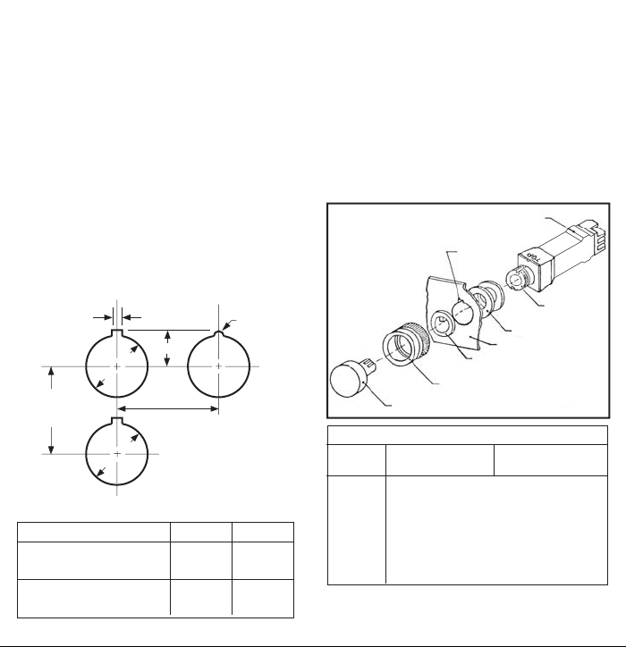
Step 1. Remove the mounting ring from the bushing.
Step 2. Select the proper combination of gaskets for the
panel thickness from Table 1 below, and install
them on the bushing.
Step 3. Insert the bushing through the panel from the rear.
The surface marked "top" should be in line with
the anti-turn notch in the panel.
Step 4. Install the legend plate (or positioning ring) on the
bushing, in line with the anti-turn notch in the
panel.
Step 5. Turn the mounting ring onto the bushing until it
stops, to compress the gaskets, and secure the
unit on the panel.
Note: To remove the entire unit from the panel, reverse
Steps 4 and 5.
PANEL MOUNTING PLAN
PREFERRED
1/8"
1/2"
7/8" Dia.
A
VERTICAL
SPACING
7/8" Dia.
B
HORIZONTAL
SPACING
Type of Unit A Min. B Min.
All Bulletin 800MS, Bulletin
800MR Standard Legend Plate
Bulletin 800MR Large
Legend Plate
1-1/4" 1-1/4"
1-1/2" 1-1/4"
1/8" Diameter
Drill (Alternate)
BULB REPLACEMENT INSTRUCTIONS
1. Remove the lens assembly by grasping the lens cap
firmly with a pair of pliers and pull the assembly straight
out of the bushing.
2. Remove the bulb by pushing and turning it
conterclockwise using the small end of the bulb
remover (Allen-Bradley Catalog Number 800T-N82),
and insert a new bulb using the same action in the
clockwise direction.
3. Snap the lens assembly back into the bushing.
Operator Assembly
Anti-Turn
Notch
Bushing
Gaskets
Panel
Positioning Ring
Mounting Ring
Lens Assembly
Table 1 Number of Gaskets Required
Panel
1/16"
3/32"
1/8"
5/32"
3/16"
7/32"
1/4"
For intermediate panel thickness, use the combination
specified for the smaller panel listed above. Panels thicker
than 1/4" must be counterbored 2" minimum diameter to 1/4".
.067" Gasket
(Black)
3
3
3
2
2
1
1
Plus
Plus
Plus
Plus
Plus
Plus
Plus
.034" Gasket
(Red)
2
1
0
1
0
1
0
Page 2
BULLETIN 800MS MOUNTING INSTRUCTIONS
PILOT LIGHT AND PUSH-TO-TEST UNITS
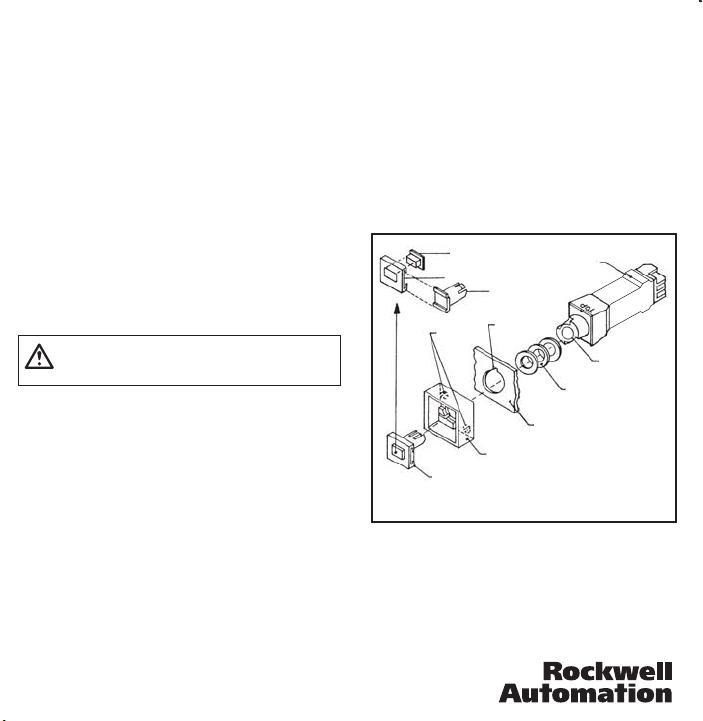
Step 1. Remove the lens assembly (or legend support) by
inserting a screwdriver between the assembly and
the bezel and gently pry the assembly out.
Step 2. If the two cam fasteners inside the bezel are
locked, turn them to their unlocked positions
(sloping surfaces facing each other and slots in
line). Pull the bezel off the unit.
Step 3. Select the proper number of gaskets for the panel
thickness and install them on the bushing. Note:
Use only the combination of gaskets specified in
Table 1 on the opposite side.
Step 4. Insert the bushing through the panel, and snap the
bezel on the bushing. The switch surface marked
"top", the locator tab on the rear surface of the
bezel and the anti-turn notch in the panel must be
in line.
Step 5. Fasten the unit on the panel by turning the two
cam fasteners 180˚ to their locked positions.
ATTENTION: This step must be completed to securely
fasten the unit on the panel, and to compress the gaskets
behind the panel.
Step 6. Assemble the legend plate and lens by pushing
the lens through the hole in the legend plate from
the rear. Then slide the legend support into the
slots in the legend plate from the side, so that the
plate is centered on the support.
Step 7. Snap the lens assembly into the bushing in the
proper orientation. Note: See Step 1 for lens
assembly removal, if required.
Step 8. Check for proper installation by pushing on the
lens assembly.
If the unit is pushed out of the bezel, or is loose on the
panel, check for the proper combination of gaskets (Step 3),
and the proper cam fastener engagement (Step 5).
Push-To-Test Units: If the lens assembly does not return
freely, check for the proper combination of gaskets (Step 3).
Note: To remove the entire unit from panel, reverse Steps
4, 5 and 7.
40060-008-01 (A)
Printed in U.S.A.
BULB REPLACEMENT INSTRUCTIONS
1. Remove the lens assembly as described in Step 1.
2. Remove the bulb by pushing and turning it
counterclockwise using the small end of the bulb
remover (Allen-Bradley Catalog Number 800T-N82),
and insert a new bulb using the same action in the
clockwise direction.
3. Snap the lens assembly back into the bushing.
Lens
Legend Plate
Cam
Fasteners
Bezel
Lens Assembly
Legend
Support
Anti-Turn
Notch
Operator
Assembly
Panel
Bushing
Gaskets
 Loading...