

Page 1
INSTALLATION INSTRUCTIONS
800HL-EMP SELECTOR SWITCHES
FOR NEMA TYPE 7 [3/8" (9.5) TO 2-1/2" (50.8)
PANELS] AND TYPE 9 [7/32" (7.2) TO 2-1/2" (50.8) PANELS]
(Dimensions shown in parentheses are in millimeters)
�
WARNING
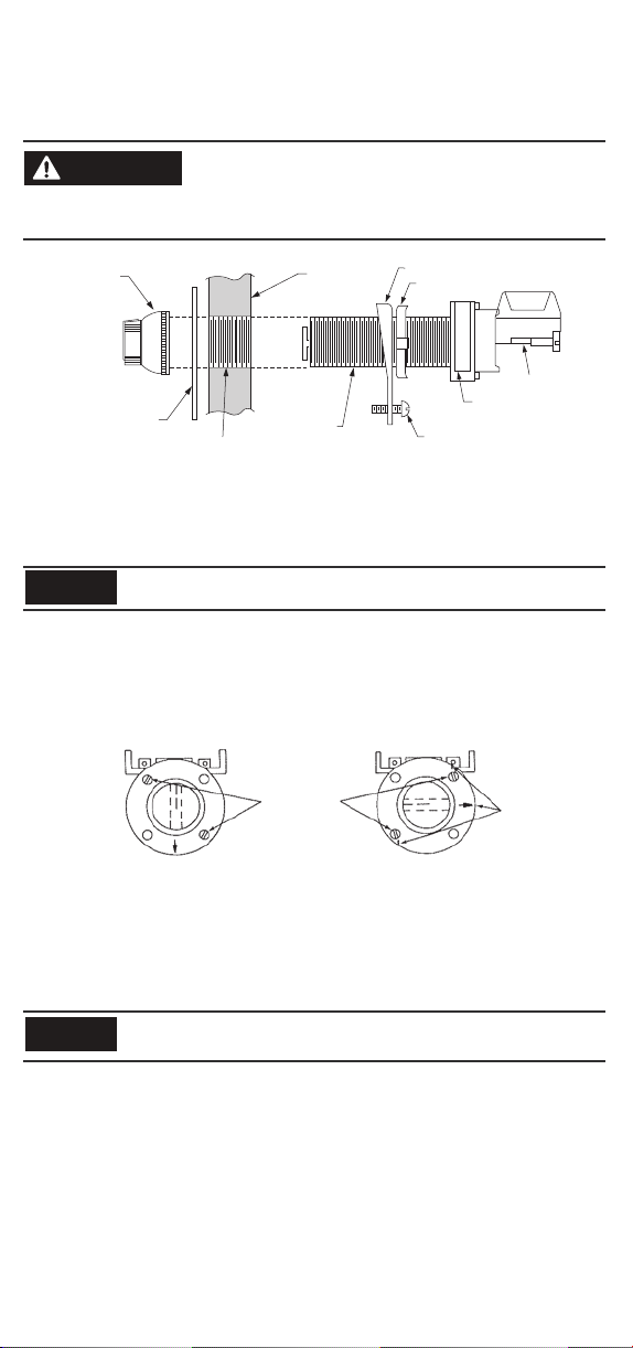
STANDARD
KNOB
LEGEND PLATE
To a vo id d am ag e to e qu ip me nt or in ju ry t o pe rs onne l, e le ct ri cal
power must be off before and during installation and maintenance.
Ma in t ain ½ " (1 2 .7) m in i mu m cl e a ra nc e t hro ug h a ir be tw e en
current-carrying parts and enclosure.
PANEL � �
MOUNTING
�
�
BUSHING
Figure 1
SECURING RING
ADJUSTING NUT
LOCKING SCREW
CONTACT BLOCK
NAMEPLATE
Installation: See Figure 1 for illustrated assembly
1. Pla ce sec urin g ring a nd/o r adju stin g nut as s uppl ied on u nit as s hown a bove a nd thr ead un it int o
panel until bushing ex tends approximatel y 9/32" (7.1) [3 to 4 threads ] past front of panel. 7/3 2" (5.6)
[2 to 3 threads] if a legend plate is not to be used.
NOTICE
2. To secur e unit, ro tate to ass ure elec trical cl earance a nd tight en adjust ing nut an d/or lock ing screw
sec urel y. Where t wo un its a re mou nted adj ace nt to e ach ot her, arr ang e secu ring rin gs to a voi d
interference.
3. Place legend plate, if used, over mounting bushing.
The specified extension of the bushing is necessary to provide engagement of the operating knob.
FLAT HEAD
SCREWS
REFERENCE MARKS
Device For Vertical Mounting
Front View
Device For Horizontal Mounting
Front View
Figure 2
NOTE: Remove knob, lever or key before modification.
1. Wi th a fel t pen o r cray on , mak e refe ren ce mar ks on t he mou nti ng bus hi ng to i dent ify t he sid e
adjacent to the nameplate and the holes in which the flat-head screws are assembled.
2. Remove the two flat-head screws and lift the mounting bushing straight off of the base. Do not twist.
Do not rotate any parts within either t he base assembly or the mounting bushi ng while these two
NOTICE
3. 2 an d 3 pos iti on se lec tor swit ches: Wh ile sepa rat ed from th e base, tu rn the mou nti ng bushi ng
counterclockwise 90° and reassemble the unit.
4 position se lector swi tches: Whil e separated f rom the base, t urn the mount ing bushin g clockwise
90° and reassemble the unit.
NOTE: In the proper position originally - used mounting screw holes will be aligned with tapped h oles in
the base.
4. Reassemble and torque the two flat-head screws to 8
5. Check the switch for proper operation and correct contact action.
To assemble th e operating kn ob, align the co lored insert w ith the rivet of t he shaft plate (s ee Figure 3).
Tig hte n the k nob as sembly o nto t he mo unt ing b ush ing . Kno b asse mbly sho uld c lam p leg end p lat e
tightly when properly assembled.
subassem blies are separate d from each ot her, as this c an cause incorrect sw itch operation aft er
reassembly.
±
1 lb.-in.
Page 2
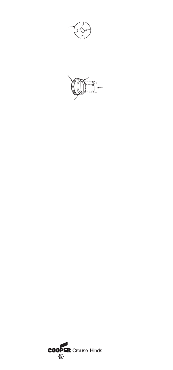
SHAFT PLATE
RIVET
Figure 3
Knobs have repl aceable color i nserts. To remo ve place sharp in strument unde r insert at the mou nting ring
and pry u p. Gra sp ins ert and r emov e from op erat or. To i nstal l new in sert, p lace i nto sl ot in ope rato r and
apply light pressure to assure seating place (see Figure 4).
MOUNTING
RING
KNOB
ASSEMBLY
KNOB
Enclosur e must comp ly with U.L. s tandards 6 98 and 1203 an d CSA stand ard C22.2 No . 30 for Class I
Gro ups B, C a nd D ha zar dou s loca tions or C 22.2 N o. 25 for Cl ass II G roups E, F a nd G haz ardous
locations. For Class I locations, a suitable seal fitting is required within 18 inches.
Figure 4
PRY UP HERE
INSERT
Hole size to be .958 (24.30) to .970 diameter (24.60) ¾-14NPSM tap.
Apply grease from caps ule (supplied) to thre ads of ¾-14NPSM hole befo re assembling units in to panel
and to the threads of the lens assembly.
Maximum p anel thic kness is 2- 1/2" (63. 5). For pan els above 2 " (50.8) bu t not excee ding 2-1 /2" (63.5 )
remove and discard securing ring and tighten device with adjusting nut only.
For Class I Group B application, 5/8" (15.9) minimum panel thickness is required.
PN-25582
DIR 10000008895 (Version 01)
Printed in U.S.A.
0359 II 2 G EEx d IIB + Hydrogen ITS07ATEX15664U
SYRACUSE, NY 13221 USA
 Loading...