

Page 1
INSTALLATION INSTRUCTIONS 800HL-EMP POTENTIOMETER
FOR NEMA TYPE 7 [3/8" (9.5) TO 2-1/2" (50.8) PANELS]
AND TYPE 9 [7/32" (7.2) TO 2-1/2" (50.8) PANELS]
WARNING
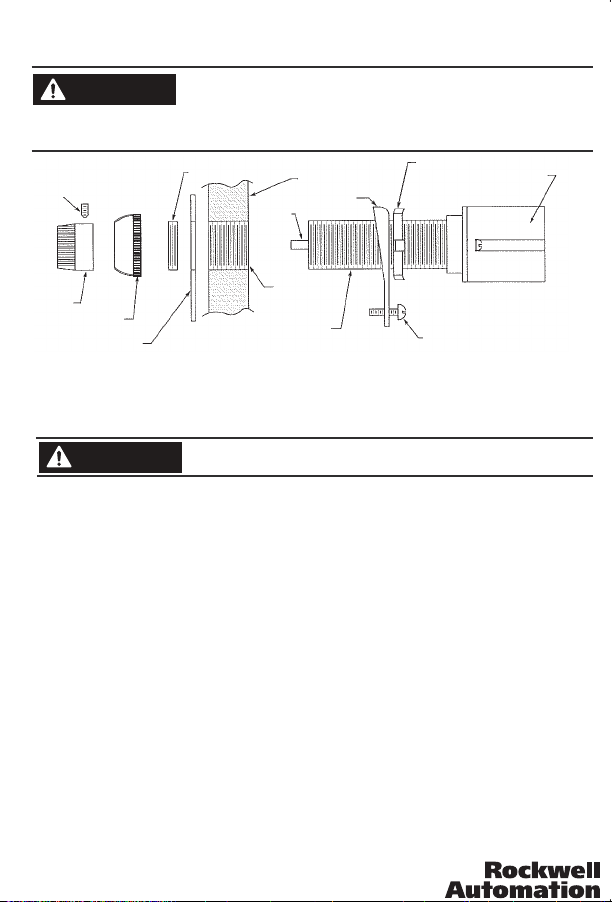
SET SCREWS
1/16" (1.6) HEX WRENCH
TIGHTEN TO 4 ± 1/2 LB-IN
�
To av oi d damag e to e qui pm en t or in ju ry to per so nnel, e le ctric al p ower
must be off before and during installation and maintenance.
M ai n t ai n ½ " ( 12 . 7 ) mi n i mu m c le a r an c e t hr o u gh a i r be tw ee n
current-carrying parts and enclosure.
ADAPTER RING
SHAFT
PANEL
� � �
SECURING RING
ADJUSTING NUT
HOUSING
KNOB
MOUNTING RING
LEGEND PLATE
Installation: See Figure 1 for illustrated assembly.
1. Plac e secur ing rin g and/o r adjus ting nu t as supp lied on u nit and t hread u nit int o panel u ntil bu shing e xtend s
approxim ately 11/3 2" (8.7) [4 to 5 t hreads], p ast front o f panel - 9/32 " (7.1) [3 to 4 th reads] if a le gend plate i s
not to be used, see Figure 3.
To secure unit, rotate t o a position which prov ides electrical clea rance and tighten adju sting nut and/or lock ing
2.
screw. Where two units are mounted adjacently, arrange securing rings to avoid interference.
3.
WARNING
Place legend plate, if to be used, over mounting bushing.
4.
Assemble mounting ring adapter and tighten.
5.
Rotate shaft counterclockwise to stop.
6.
Position knob on shaft aligning white indexer on knob with "min." increment marking on legend plate.
7.
Tighten the two set screws in the knob to 4 ± ½ lb.-in. with a 1/16" (1.6) hex wrench.
8.
Install mounting ring and tighten. Allen-Bradley Catalog No. 800T-N3 wrench is available for this operation.
9.
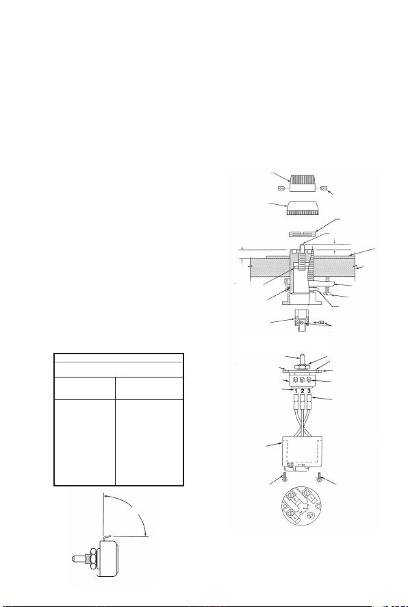
Replacing Potentiometer: See Figure 3 for illustrated assembly.
NOTE 1: Refer to nameplate on housing for original potentiometer resistance.
NOTE 2: Unit need not be removed from enclosure to replace potentiometer.Potentiometer Removal:
1. Remove the two screws on the rear of the housing and pull the housing (see Figure 3) from the bushing.
2. Disconnect the three wire leads from the potentiometer terminals.
3. Loose n the two se t screw s in the sha ft adapt er with a 1 /16" (1. 6) hex wre nch and r emove sh aft adap ter from
potentiometer shaft.
4. Remove nut, lockwasher and mounting plate.
Potentiometer Installation:
Remove mount ing ring leavi ng mounting r ing adapter in p lace. Allen -Bradley Cat alog No. 800T- N3 wrench is
1.
available for this operation.
Loosen the two set screws in the knob with a 1/16" (1.6) hex wrench and remove knob.
2.
Rotate shaft so that it extends .40 ± .01 (10.2 ± .2) from bushing.
3.
Bef or e ins talli ng po tenti om ete r bend th e thr ee term in als 8 0° - 90° a nd remo ve nu t and loc kw ash er f rom
4.
bushing (see Figure 2).
5. Ins ta ll mou ntin g plat e, pr in te d side f acin g out wa rd , over p oten tio me te r shaf t alig ning l oca ti ng t ab on
potentiometer with slot in mounting plate.
Tighten nut and lockwasher on potentiometer shaft and bend locating tab to fit mounting plate.
6.
Insert wire l eads onto the p otentiome ter termina ls making sur e the leads ide ntified as 1, 2 a nd 3 are attach ed
7.
to th e cor res pon din gly i den tif ied p ote nti ome ter t erm ina ls. ( See F igu re 3 fo r ter min al id ent ifi cat ion .) If t he
potentiom eter housi ng does not ha ve wires with t erminal lu gs, cut and st rip the wires a nd solder th e wire end
to the appropriate potentiometer terminal.
40060-303-01 Ver (05)
Printed in U.S.A
Wh en I nst al li ng in a met al e nc losur e, m ai ntai n 1/2” (1 2. 7) m inimu m
clearance through air between current carrying parts enclosure.
�
� �
MOUNTING BUSHING
Figure 1
LOCKING SCREW
Page 2
8. Rotate potentiometer clockwise to stop.
9. Place shaft adapter onto potentiometer shaft. Rotate shaft adapter to orient slot in shaft adapter with roll pin
in shaft while holes in diaphragm and mounting plate are in line with holes in mounting bushing.
Tighten the two set screws in the shaft adapter to 4 ± ½ lb.-in. with a 1/16" (1.6) hex wrench.
10.
11. Line up holes in housing, mounting plate, and mounting bushing and push the unit into the mounting
bushing.
12. Secure by threading in the two screws from the rear of the potentiometer housing.
13. Rotate shaft counterclockwise to stop.
14. Position knob on shaft aligning white indexer on knob with "min." increment marking on legend plate.
15. Tighten the two set screws in the knob to 4 ± ½ lb.-in. with a 1/16" (1.6) hex wrench.
16. Install mounting ring and tighten. Allen-Bradley Catalog No. 800T-N3 wrench is available for this operation.
Enclosure must comply with U.L. standards 698 and 1203 and CSA standard C22.2 No. 30 for Class I
Groups B, C and D hazardous locations or C22.2 No. 25 for Class II Groups E, F and G hazardous locations.
For Class I locations, a suitable seal fitting is required within 18 inches.
Hole size to be .958 (24.3 Ø) to .970 diameter (24.6 Ø) ¾-14NPSM tap.
Apply grease from capsule (supplied) to threads of ¾-14NPSM hole before assembling units into panel and
to the threads of the lens assembly.
For standard length units (Bul. 800H), maximum panel
thickness is 1” (25.4). From 3/4” (9.5) to 23/32” (18.3)
securing ring is used as shown, without adjusting nut.
Securing ring is reversed when panel thickness is from
23/32” (18.3) to 29/32” (23) and eliminated between 29/32”
(23) and 1” (25.4).
For long barrel units (Bul. 800H), maximum panel thicknes
is 21/2” (63.5). For panels above 2” (50.8) but not
exceeding 21/2” (63.5) remove and discard securing ring
and tighten device with adjusting nut only.
For Class I Group B application, 5/8" (15.9) minimum
panel thickness is required.
Power Rating:
Maximum power (P) = 2 watts provided maximum working
voltage is not exceeded.
Maximum working voltage (EMAX) shall not exceed 300
volts (RMS or DC) or as determined by EMAX=�P R, R =
resistance, whichever is less. See Table 1 for power
Table 1
Power derating with respect to rotation
for rheostat application
Percent
Rotation
100 1.00
90 .99
80 .98
70 .96
60 .93
50 .89
40 .81
30 .68
20 .49
10 .23
0 .11
Multiplying
Wattage
Rating By
KNOB
MOUNTING
RING
11/32 (8.7) IF
LEGEND PLATE
IS TO BE USED
9/32 (7.1) IF
LEGEND PLATE
IS NOT TO BE USED
ROLL PIN
MOUNTING
BUSHING
SHAFT ADAPTER
DIAPHRAGM
POTENTIOMETER SHAFT
LOCATING TAB
POTENTIOMETER
TERMINAL
IDENTIFICATION
HOUSING
MOUNTING
SCREW
SET SCREWS
1/16" (1.6) HEX WRENCH
TIGHTEN TO 4 ± 1/2 LB-IN
MOUNTING RING
ADAPTER
SHAFT
40 ± .01 (10.2 ± 2)
SECURING RING
LOCKING SCREW
ADJUSTING NUT
SET SCREWS
1/16" (1.6) HEX WRENCH
TIGHTEN TO 4 ± 1/2 LB-IN
NUT AND LOCKWASHER
PRINTED SIDE
MOUNTING PLATE
POTENTIOMETER
TERMINAL
WIRE LEAD
MOUNTING
SCREW
LEGEND
PLATE
ENCLOSURE
40060-303-01 Ver (05)
Printed in U.S.A
�
80° - 90°
Figure 2
Figure 3
NOTE:
WIRE RANGE:
18-14 AWG (0.5-2.5mm2)
TIGHTENING TORQUE:
6-7lb.in (0.7-0.8 Nm)
 Loading...