

Page 1
Installation Instructions
Bulletin 700 Type RTC & RTCR Solid-State
Relays
Instruction Sheet
Description
Important: Save these instructions for future reference.
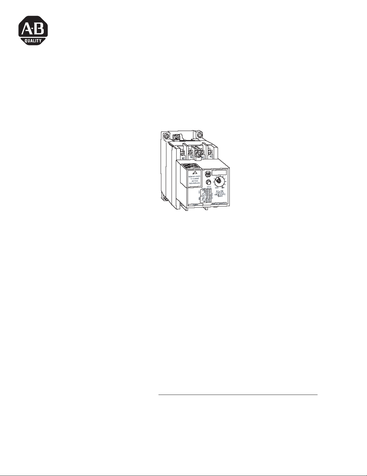
Bulletin 700 Type RTC relays are designed for industrial environments. They
offer the reliability and accuracy of solid-state timing along with the contact
isolation of conventional electromechanical relays. The contacts are
hermetically sealed in glass for reliability.
Type RTC relays are available with up to two timed contacts and two
nstantaneous contacts in any N.O. – N.C. combination. A sixteen position
i
rotary switch is used to set the mode to on-delay or off-delay, and there are
eight timing ranges in each mode. The timing period is set by means of a
self-contained potentiometer in the Type RTC relays. Relays with provisions
for an external timing adjustment potentiometer are identified as Type RTCR.
The N.O. and N.C. contacts are designed to be changed or added in the field.
relay can be easily modified to have any combination of N.O. and N.C.
A
contacts, limited to two timed and two instantaneous contacts maximum.
Note: If
instantaneous positions of C5/C6 and C7/C8, they must NOT be field
installed.
(2) Normally Closed (N.C.) contact cartridges are required for the
Please order this contact configuration direct from the factory.
UL Listed
1 Publication 700-IN003C-EN-P - October 2009
Bulletin 700 Type RTC relays are listed by Underwriters’ Laboratories, Inc. for
use in Class I, Division 2, Groups A, B, C, and D hazardous locations as
defined by the National Electric Code.
Page 2
2 Bulletin 700 Type RTC & RTCR Solid-State Relays
ATTENTION
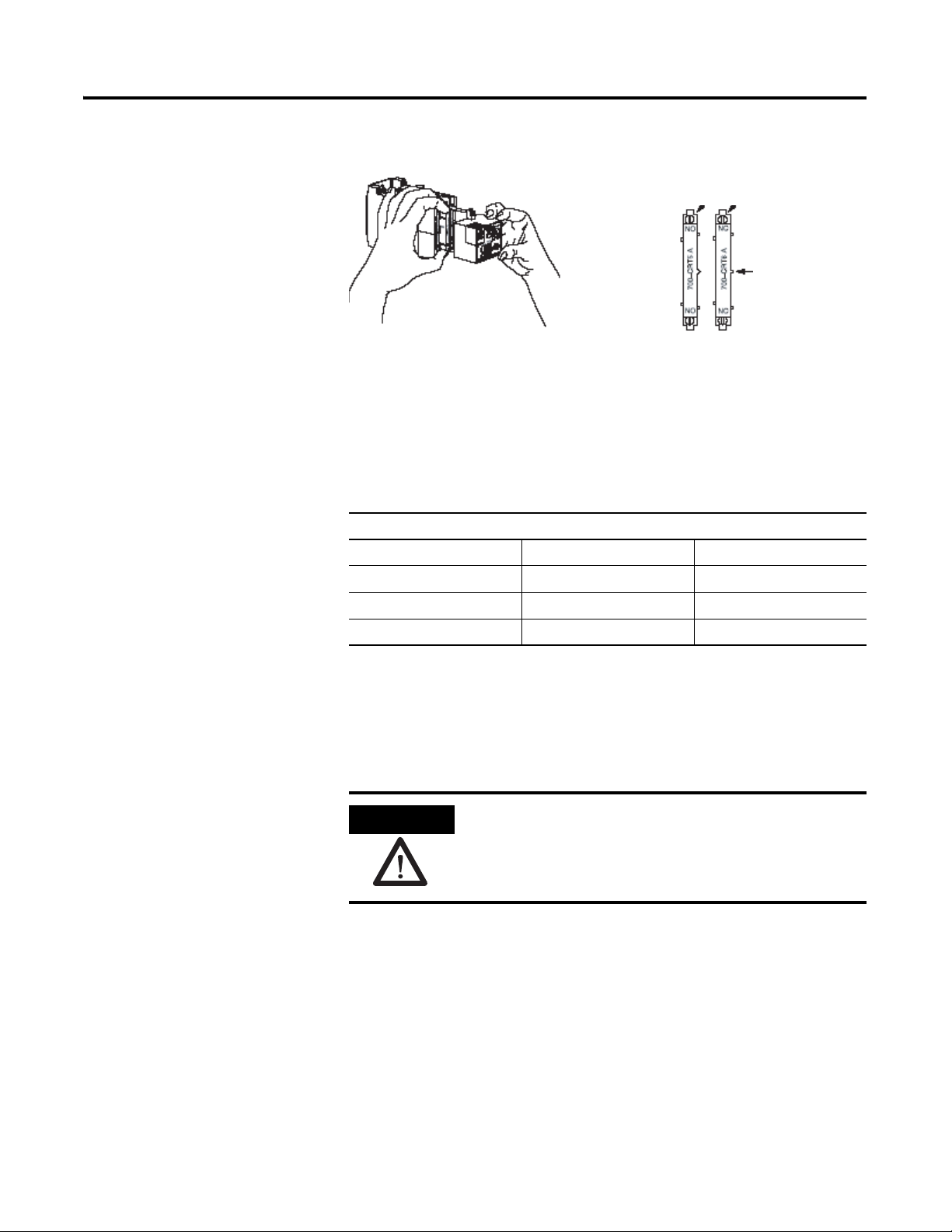
Orientation of cartridges
Method of removing cartridge
Projection for Keying
Insert cartridge with this end at top of timer
Adding or Changing Contact Cartridges
Figure 1. Removing and Orientation of Cartridges
Timers are supplied with two slots for timed contacts and two slots for
instantaneous contacts. “Dummy” cartridges are placed in any unused
cartridge slots to guard against entrance of foreign material.
Contact Cartridges
Ty pe Color Catalog Number
Normally Open Gray 700-CRT5
Normally Closed Orange 700-CRT6
Dummy Black 700-CR9
The N.O. cartridges, N.C. cartridges, and dummy cartridges are removable and
interchangeable using the same cartridges for both timed and instantaneous
slots, with the exception of the N.C. cartridges in the instantaneous positions
(reference Note on page 1) Use the following procedure:
1. Disconnect all power from timer or timer panel.
2. Loosen the two front housing screws (See Figure 1.) until the housing
slides back along the screws for approximately one inch. The screws are
captive and will restrain the front housing to protect the circuit cable
that connects to the timer base.
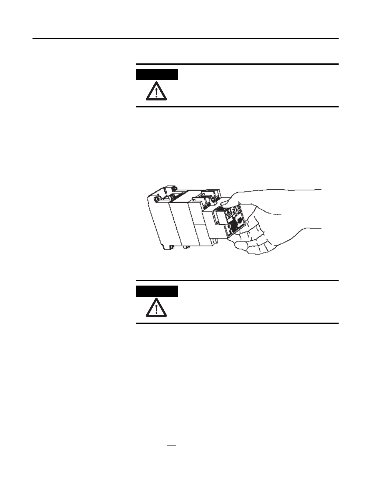
The glass envelopes in the N.O. and N.C. cartridges can be
damaged if dropped or mishandled. Damaged cartridges
must be replaced.
Publication 700-IN003C-EN-P - October 2009
3. Remove the N.O. or N.C. contact or the dummy cartridge by lifting it
out of the slot. A screwdriver is required to pry out the dummy
cartridge.
Page 3
Bulletin 700 Type RTC & RTCR Solid-State Relays 3
ATTENTION
ATTENTION
Be careful not to damage circuit table.
4. Insert the desired cartridge. The cartridges are keyed and must be
inserted with correct orientation (See Figure 1.).
5. Slide front housing back down carefully to avoid cable damage. Tighten
screws.
Setting the Mode and Timing Range
Figure 2. Removing Corner Cover
Method of removing corner cover
Unpredictable contact operation can occur if the mode
setting is changed with power applied to any terminal.
1. Remove the corner cover by pressing down on the top of the cover with
your thumb and slide forward (See Figure 2.).
Operation
2. Set the desired position on the sixteen position rotary switch using a
small screwdriver.
3. Replace corner cover by sliding it back into its original position.
Table 1 outlines timer operation in both the on-delay and off-delay modes.
The red LED indicator on the front housing of the timer gives visual
indication of timing, timed out, and reset or stable timer conditions. At certain
settings, there may be a slight delay in the LED operation. The timing
sequence is
not affected by this delay.
Publication 700-IN003C-EN-P - October 2009
Page 4

4 Bulletin 700 Type RTC & RTCR Solid-State Relays
Table 1 Timer Operation
Operating
Mode
On-delay On No Reset Off Open Closed Open Closed
Off-delay On Yes Reset On Closed Open Closed Open
Power
(Terminals
L1-L2)
Off No Stable Off Open Closed Open Closed
Off No Stable Off Open Closed Open Closed
Voltage
(Applied to
Initiate
Terminal P)
Yes Timing Flashing Closed Open Open Closed
Yes Timed Out On Closed Open Closed Open
Yes Stable Off Closed Open Open Closed
No Timing Flashing Open Closed Closed Open
No Timed Out Off Open Closed Open Closed
Yes Stable Off Closed Open Open Closed
Timer Status Red LED
ndicator
I
Contact Cartridge Statue
Instantaneous Tim ed
N.O N.C N.O N.C
Note: When the timer is energized or times out in the on-delay mode, an
N.O. contact may close before an N.C. contact opens; this can occur because
of inherent operating characteristics. Similarly, when the timer is de-energized
or times out in the off-delay mode, an N.C. contact may close before an N.O.
opens. Assured contact overlap or non-overlap cannot be provided in the same
device.
Terminals
Wiring
Terminal clamps are designed for solid or stranded copper wire (strip ends to
7.9mm [5/16”]). Use 7 - 8 lb.-in. of torque to tighten the terminal clamps. Wire
size: (1) #18 AWG (.75mm
2
) minimum to (2) #12 AWG (14.0mm2)
maximum.
Make connections as shown in Figure 3. Power is applied continuously to
terminals L1 and L2. Voltage applied and r
emoved at initiating terminal P will
operate the instantaneous contacts and initiate timing as indicated in Table 1.
Use insulated copper wire rated at 75
°C (167°F) or higher.
Publication 700-IN003C-EN-P - October 2009
Page 5

Bulletin 700 Type RTC & RTCR Solid-State Relays 5
Figure 3 Timer Power and Initiate Circuit Connections
24V (+10%, -15%) AC or DC
120V (+10%, -15%) AC or DC
External Initiating Contact
(N.O. or N.C.)
Timed Contacts - Any
Combination of N.O. and N.C.
240V (+10%, -15%) AC or DC
P
Timed
C3
C1
C2
C4
C5
C6
Inst.
C7
C8
Connecting Remote Potentiometer
Instantaneous Contacts - Any
Combination of N.O. and N.C.
L1
L2
Type RTCR Timing Relays are designed for use with an external potentiometer
(400K ohms maximum resistance). Recommended potentiometers and
required connecting cables are listed below.
Potentiometer Construction Catalog Number
Bulletin 800T NEMA Type 13 Oiltight 800T-U90
Bulletin 800MR Small NEMA Type 13 Oiltight - Round 800MR-N37
➊
Bulletin 800MS Small NEMA Type 13 Oiltight - Square 800MS-N37 ➊
➊ 1 operator only - suitable for 400K ohm potentiometer.
Connection Cable – Use shielded twisted pair cable, maximum of 50 feet.
Recommended cable (or equivalent): UL Style 2517, having two #18 stranded
conductors with aluminum mylar foil shield and #20 drain wire rated 105_C
(221_F), FR–1, 300V.
In the connection drawing (See Figure 4 on page 6), note that the shield is
connected to the terminal marked “Shield” at one end and is insulated and not
nnected at the other end. The L2 terminal should be grounded at the power
co
source.
Publication 700-IN003C-EN-P - October 2009
Page 6

6 Bulletin 700 Type RTC & RTCR Solid-State Relays
120V AC or DC
240V AC or DC
Figure 4 Remote Potentiometer Connections
Manual Actuator
Specifications
Timer can be equipped with a manual actuator (Cat. No. 700–N7) which is
used to energize the initiate circuit (Terminal P) manually using a separate
voltage source, 24V and 120V AC/DC only. It can be easily installed in the
field.
Table 2 Voltage and Power Requirements
AC Voltage 50/60 Hz
+10%, -15%
24V AC 8VA 4VA U24
110-120V AC 9VA 4VA U1
220-240V AC 11VA 5VA U2
DC Voltage
+10%, -20%
24V DC 10 W 5 W U24
120V DC 11 W 5 W U1
240V DC 12 W 5 W U2
Total Power
Required
Total Power
equired
R
Initiate Terminal P
Power
Initiate Terminal P
Power
Coil Code
Coil Code
Publication 700-IN003C-EN-P - October 2009
Repeat Accuracy: ±1% or ±50 milliseconds at constant voltage and
temperature.
Maximum Available Leakage Currents: 240V – 2.4 m
A RMS, 120V – 2.4
mA RMS, 24V – 10 mA RMS.
Reset Time: 25 millise
Operating Mode: O
conds required.
n-Delay and Off-Delay. For instructions, refer to “Setting
the Mode and Timing Range” on page 3.
Timing Ranges and Switch Positions – Types RTC and RTCR
Page 7

Specifications (continued)
On-Delay Off-Delay
Tim ing
Range
(Seconds)
2.0-120 8 1-64 C 2.0-120 0 1-64 4
0.4-30 9 0.25-16 D 0.4-30 1 0.25-16 5
0.2-8 A 0.06-4 E 0.2-8 2 0.06-4 6
0.05-2 B 0.015-1 F 0.05-2 3 0.015-1 7
Switch
ition
Pos
Bulletin 700 Type RTC & RTCR Solid-State Relays 7
Timing Range
(Minutes)
Switch
Position
Timing
Range
(Seconds)
Switch
sition
Po
Timing Range
(Minutes)
Temperature Range: –20°C to +60°C (–4°F to +140°F)
Switch Position
For altitudes above 2000 meters (1.24 miles): –20°C t
+122°F). For CONTINUOUS DUTY and units placed close or next to each
o +50°C (–4°F to
other (3 in a row), use –20°C to 45°C (–4°F to +113°F) or circulate air around
units.
Table 3 Contact Rating - NEMA B600, P300
AC, 50/60 Hz - NEMA B600 DC - NEMA P300
Maximum Volts Amperes Voltamperes Maximum Volts Amperes Voltamperes
Make Break Make Break
120 30 3.00
240 15 1.50
480 7.5 075
125
3600 360
250
1.1
138
0.55
600 6 0.60
Continuous Current Rating: 5 Amps Continuous Current Rating: 5 Amps
Dimensions
These timing relays can be mounted directly on a panel or installed on Bulletin
700 Type MP mounting strips. Dimensions are shown below.
Mounting Dimensions
Dimensions in millimeters (inches). Dimensions are approximate and are not
intended to be used for manufacturing purposes.
Enclosure Dimensions
124mm (4.88”) x 195mm (7.69”) x 178mm (7”) deep (Cat. No. 700-N31).
Publication 700-IN003C-EN-P - October 2009
Page 8

Publication 700-IN003C-EN-P - October 2009 8 PN 40052-307-01 (7)
Supersedes Publication 700-IN003B- EN-P - July 2008 Copyright © 2009 Rockwell Automation, Inc . All rights reserved. Printed in the U.S.A.
 Loading...