

Page 1
Electronic Timer
Minuterie électronique
Elektronisches Zeitrelais
Temporizzatore elettronico
Temporizador electronico
Temporizador eletrônico
(Cat 700-HRV52_ _)
Attention: To prevent electrical shock, disconnect from power source before installing or servicing. Do not open the
apparatus.
Attention: Avant le montage et la mise en service, couper l'alimentation secteur afin d’éviter tout accident. Ne pas ouvrir
l’appareil.
Achtung: Um Unfälle zu vermeiden, Installations- oder Servicearbeiten nur im spannungsfreien Zustand.
Gehäuse niemals öffnen.
Attenzione: Per prevenire infortuni, togliere tensione prima dell'installazione o manutenzione. Non aprire l’apparecchio.
Atención: Desconectar la alimentación eléctrica antes de realizar el montaje y la puesta en servicio, con el objeto de evitar
accidentes. No abrir el aparato.
This product contains greater than 0.1% by weight of one or more substance of very high concern (SVHC) as defined by the REACH regulation (1907/2006).
Based on the information available to Rockwell Automation no special precautions are required to safely use this product. Rockwell Automation maintains a list
of SVHCs in its products on its website at
http://www.rockwellautomation.com/rockwellautomation/about-us/sustainability-ethics/product-environmental-compliance.page
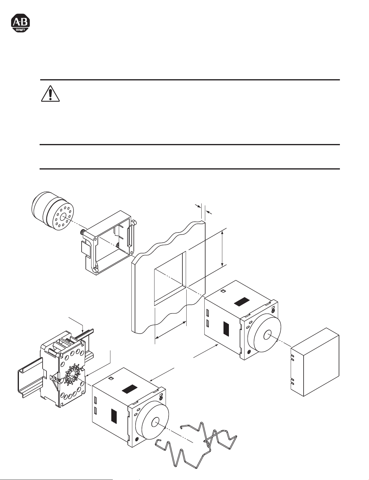
700-HN129
35mm EN50022
199-DR1
700-HN130
700-HN101, -HN126
1mm - 5mm
(0.04" - 0.19")
45mm
(1.77")
45mm
(1.77")
700-HRV52_ _
700-HN131
700-HN132
Page 2
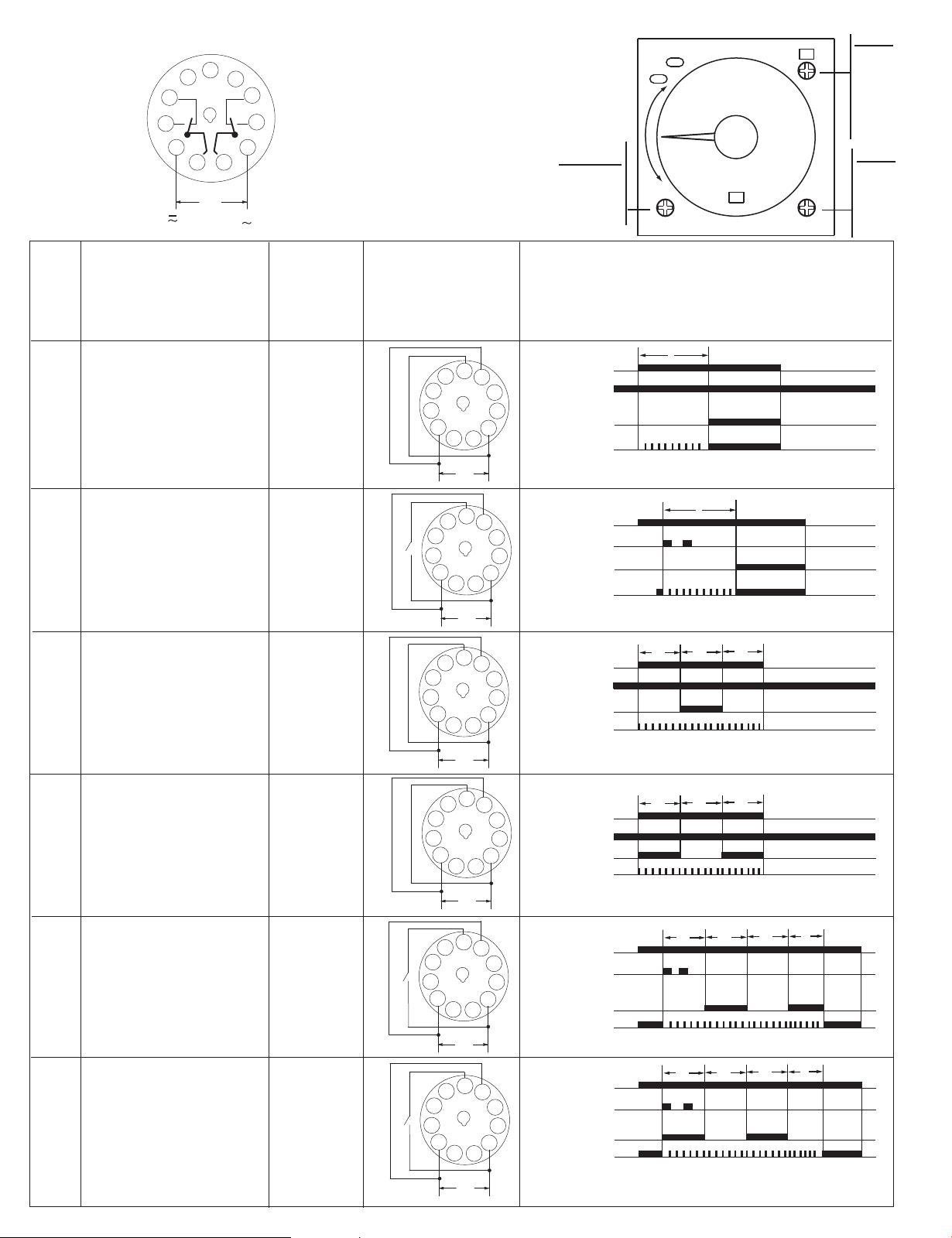
700-HRV52_ _
Output:
N.C. (1-4), (8-11)
N.O. (1-3), (9-11)
Function
Fonktion
Funktion
Funzione
Função
Función
MODE
On-Delay
A
Début de temporisation
Einschaltverzögerung
Ritardo all'eccitazione
Retardo de conexión
Retardado
22
12
14
5
4
3
2
A1
( ) ( + )
21
24
6
7
32
8
9
34
1
A2
3111
10
11
U
Trigger
Déclencheur
Auslöser
Trigger
Disparador
Disparador
Power-On
Tension
Einschalter
In corrente
Conexión
Ligado
Input Signal
Signal d'entrée
Eingangssignal
Segnale di input
Señal de entrada
Sinal de entrada
6
2
Timing diagrams
Séquences
Funktionsablauf
Schema funzionale
Diagramas
Diagrama
7
Output, UP LED
10
RANGE
0.05...1.2
0.05...3.0
0.05...12.0
0.05...30.0
(6-10)
Power LED
POWER
UP
U
T
MODE
A
B
B2
C
D
E
G
J
UNIT
sec
10s
min
10m
hrs
10h
U
MODE
A
MODE
B
MODE
B2
MODE
B
MODE
B2
On-Delay
Début de temporisation
Einschaltverzögerung
Ritardo all'eccitazione
Retardo de conexión
Retardado
Repeat Cycle, Off Start
Répéter cycle, A l'arrêt
Zyklus wiederholen, Aus/Ein
Ripetizione ciclo di accensione
Repetir ciclo, Inicio apagado
Repetir Ciclo, Início Desligado
Repeat Cycle, On Start
Répéter cycle, Au début
Zyklus wiederholen, Ein/Aus
Ripetizione ciclo di spegnimento
Repetir ciclo, Inicio encendido
Repetir Ciclo, Início Ligado
Signal-On
Signal de début
Signal ein
Segnale attivo
Señal encendida
Sinal - ligado
Power-On
Tension
Einschalter
In corrente
Conexión
Ligado
Power-On
Tension
Einschalter
In corrente
Conexión
Ligado
Signal-On
Signal de début
Signal ein
Segnale attivo
Señal encendida
Sinal - ligado
Signal-On
Signal de début
Signal ein
Segnale attivo
Señal encendida
Sinal - ligado
6
7
U
T
S (6-10)
S
2
Output, UP LED
10
Power LED
U
6
7
U
T
T
T
(6-10)
2
Output, UP LED
10
Power LED
U
6
7
U
T
(6-10)
2
10
Output, UP LED
Power LED
T
T
U
6
7
U
T
t
T
T
S (6-10)
S
2
10
Output, UP LED
Power LED
t<T
U
t
T
T
6
7
U
T
S (6-10)
S
2
Output, UP LED
10
Power LED
t<T
U
Page 3

700-HRV52_ _
Output:
N.C. (1-4), (8-11)
N.O. (1-3), (9-11)
Function
Fonktion
Funktion
Funzione
Função
Función
22
12
14
5
4
3
2
A1
( ) ( + )
21
6
11
1
U
24
7
32
8
9
34
10
A2
3111
Trigger
Déclencheur
Auslöser
Trigger
Disparador
Disparador
Input Signal
Signal d'entrée
Eingangssignal
Segnale di input
Señal de entrada
Sinal de entrada
RANGE
0.05...1.2
0.05...3.0
0.05...12.0
0.05...30.0
Timing diagrams
Séquences
Funktionsablauf
Schema funzionale
Diagramas
Diagrama
POWER
UP
MODE
A
B
B2
C
D
E
G
J
UNIT
sec
10s
min
10m
hrs
10h
MODE
C
MODE
D
MODE
E
MODE
E
Watchdog Monitor
Surveillance
Funktionsüberwachung
Monitor di controllo
Monitor de control
Signal-On/Off
Signal Début/Arrêt
Signal ein/aus
Segnale attivo/inattivo
Señal encendida/
Monitor do Controle de
impulso à conexão
Off-Delay
Arrêt de temporisation
Ausschaltverzögerung
Ritardo inattivo
Retardo apagado
Desligado - Retardo
One-Shot
Un coup
Einzelimpuls
Colpo singolo
Un golpe
Impulso à conexão
One-Shot
Un coup
Einzelimpuls
Colpo singolo
Un golpe
Impulso à conexão
Conexão do disparador
Signal-Off
Signal d'arrêt
Signal aus
Segnale inattivo
Señal apagada
Sinal - desligado
Power-On
Tension
Einschalter
In corrente
Conexión
Ligado
Signal-On
Signal de début
Signal ein
Segnale attivo
Señal encendida
Sinal - ligado
apagada
6
7
U
T
T
t
t<T
T
S (6-10)
S
2
10
Output,
UP LED
Power LED
U
6
7
U
T
t
S (6-10)
S
2
10
Output,
UP LED
Power LED
t<T
U
6
7
U
(6-10)
Output,
2
10
UP LED
Power LED
T
U
6
7
U
T
t
T
S (6-10)
S
2
10
Output,
UP LED
Power LED
t<T
MODE
G
MODE
J
Watchdog Monitor
Surveillance
Funktionsüberwachung
Monitor di controllo
Monitor de control
Monitor do Controle de
Signal-On/Off
Signal Début/Arrêt
Signal ein/aus
Segnale attivo/inattivo
Señal encendida/apagada
Sinal-ligado/desligado
impulso à conexão
Delayed One-Shot
Temporisé Un coup
Verzögerter Einzelimpuls
Colpo singolo ritardato
Un golpe con retardo
Impulso à conexão
Power-On
Tension
Einschalter
In corrente
Conexión
Alimentação-ligado
retardado
U
6
5
7
S
2
Output, UP LED
U
S (2-6)
T
T
t
Power LED
6
5
7
T
U
(2-6)
2
Output, UP LED
Power LED
1s±0.6s
t<T
T
Page 4

Trigger Connection
Connexion du déclencheur
Auslöseranschluss
Connessione trigger
Conexión de disparador
Conexão do disparador
S - Starts timing cycle.
S - Lance le temps de transition
S - startet Taktgebungszyklus
S: avvia il ciclo di temporizzazione
S - Inicia ciclo de intervalos
S - Inicia o ciclo do temporizador
S
A1
( ) ( + )
21
24
6
7
2
10
A2
U
Solid-state Signal Input (S):
Entrées de Signaux à Semi-conducteur (S):
Halbleiter-Signal-Eingãnge (S):
Entradas de Se ñal Transistorizadas (S):
Entradas de Sinal Transistorizados (S):
Entradas de estado sólido (R, S, G):
Proximity switch, photoelectric switch, etc.
Commutatuer de proximit é commutatuer photo é lectrique etc.
Näherungsschalter, photoelektrischer schalter, etc.
Conmutador de proximidad, conmutador fotoelectrico, etc.
Tomada de proximidade, tomada foto électrica, etc.
Chave de proximidade, chave fotoelétrica etc.
PNP Wiring Diagram + 700-HRV_ _ VDC supply
+ 12...24VDC
COM
S
6
7
COM
2
( )
10
(+) 12...24VDC
NPN Wiring Diagram + 700-HRV_ _ VDC supply
+ 12...24 VDC
COM
S
6
7
0 V
COM
2
( )
10
(+) 12...24 VDC
41063-205-01 (03)
2256882-0A
Printed in China
http://www.ab.com/manuals/
 Loading...