

Page 1
Electronic Timer
Minuterie électronique
Elektronisches Zeitrelais
Temporizzatore elettronico
Temporizador electronico
Temporizador eletrônico
(Cat 700-HR52_ _, 700-HRT6_ _)
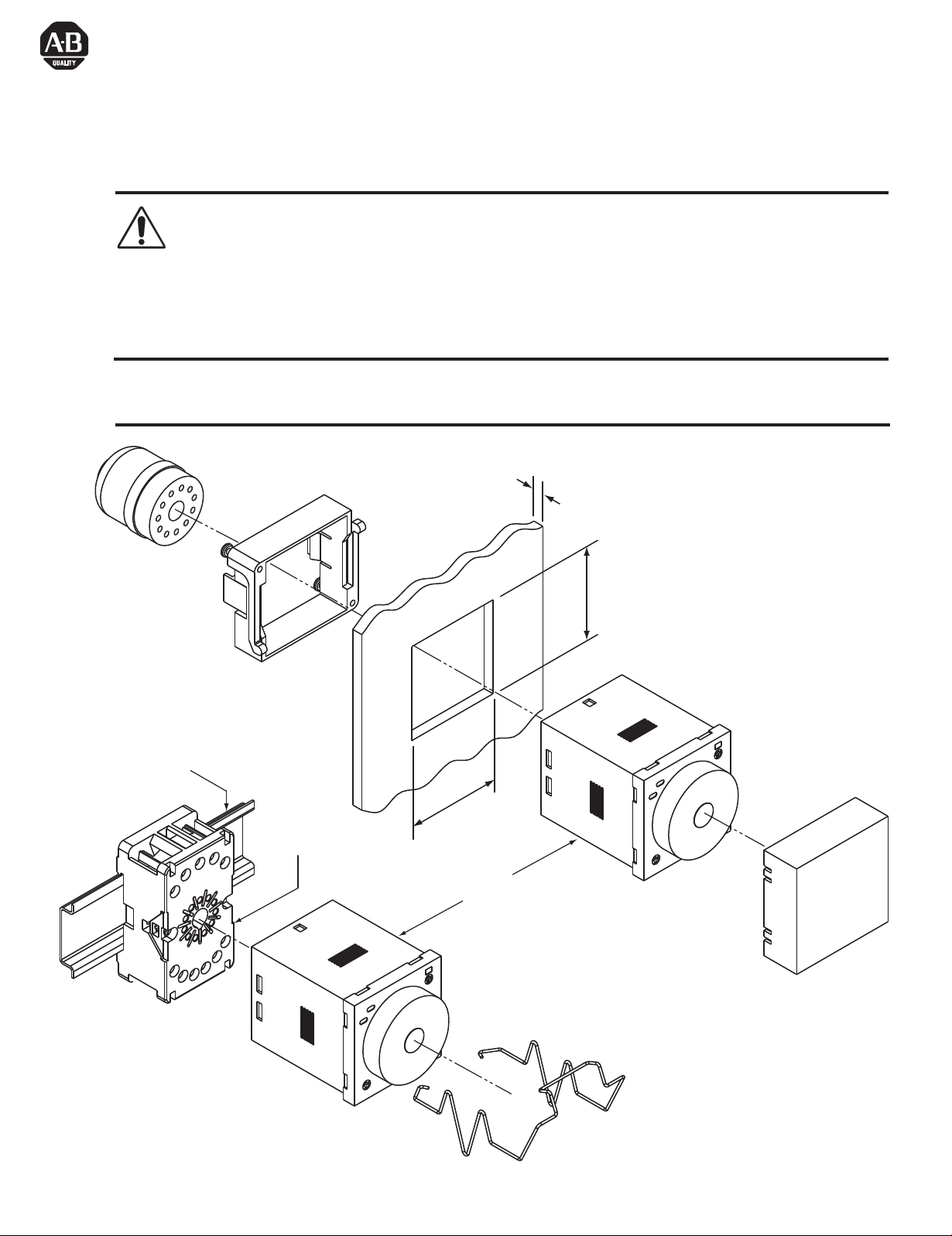
Attention: To prevent electrical shock, disconnect from power source before installing or servicing. Do not open the
apparatus.
Attention: Avant le montage et la mise en service, couper l'alimentation secteur afin d’éviter tout accident. Ne pas ouvrir
l’appareil.
Achtung: Um Unfälle zu vermeiden, Installations- oder Servicearbeiten nur im spannungsfreien Zustand.
Gehäuse niemals öffnen.
Attenzione: Per prevenire infortuni, togliere tensione prima dell'installazione o manutenzione. Non aprire l’apparecchio.
Atención: Desconectar la alimentación eléctrica antes de realizar el montaje y la puesta en servicio, con el objeto de evitar
accidentes. No abrir el aparato.
This product contains greater than 0.1% by weight of one or more substance of very high concern (SVHC) as defined by the REACH regulation (1907/2006).
Based on the information available to Rockwell Automation no special precautions are required to safely use this product. Rockwell Automation maintains a list
of SVHCs in its products on its website at
http://www.rockwellautomation.com/rockwellautomation/about-us/sustainability-ethics/product-environmental-compliance.page
1mm - 5mm
(0.04" - 0.19")
700-HN129
35mm EN50022
199-DR1
700-HN130
700-HN101, -HN126
45mm
(1.77")
45mm
(1.77")
700-HR52_ _
700-HRT6_ _
700-HN132
700-HN131
Page 2
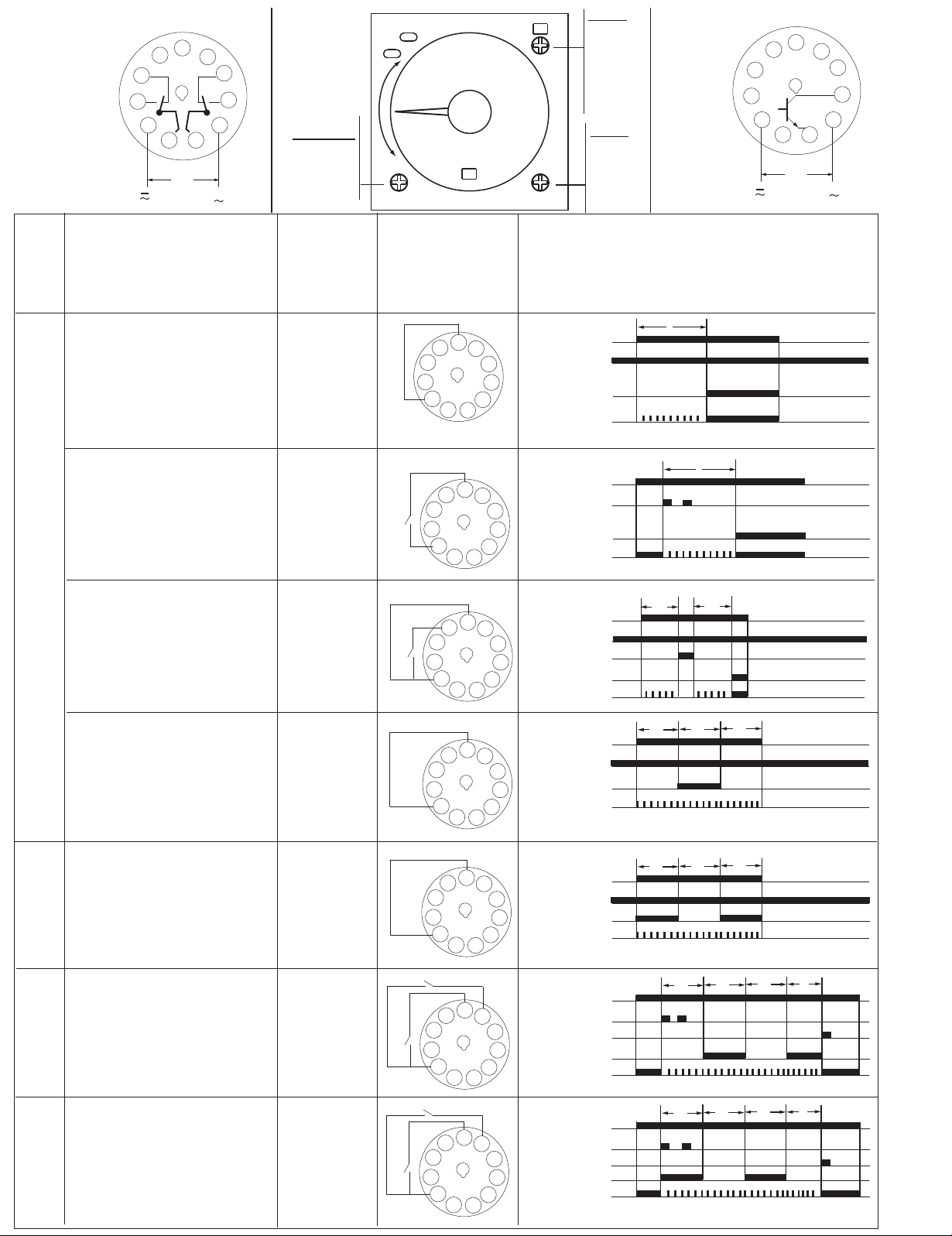
700-HR52_ _
12
14
Output:
N.C. (1-4), (8-11)
N.O. (1-3), (9-11)
Function
Fonktion
Funktion
Funzione
Função
Función
MODE
On-Delay
A
Début de temporisation
Einschaltverzögerung
Ritardo all'eccitazione
Retardo de conexión
Retardado
21
22
6
5
4
3
2
A1
7
11
1
3111
U
( ) ( + )
10
24
POWER
UP
32
8
9
34
A2
RANGE
0.05...1.2
0.05...3.0
0.05...12.0
0.05...30.0
Trigger
Déclencheur
Auslöser
Trigger
Disparador
Disparador
Power-On
Tension
0 Volt Signal
Signal 0 Volt
0-Volt-Signal
Segnale da 0 Volt
Señal de 0 voltio
Sinal de 0 Volt
6
5
7
Timing diagrams
Séquences
Funktionsablauf
Schema funzionale
Diagramas
Diagrama
Einschalter
In corrente
Conexión
2
Output, UP LED
Ligado
MODE
A
B
B2
C
D
E
G
J
UNIT
sec
10s
min
10m
hrs
10h
U
(2-6)
Power LED
700-HRT6_ _
12
14
Output:
N.O. (9-11)
T
A1
21
6
N.O.
11
24
7
10
3111
22
5
4
3
2
1
U
( ) ( + )
32
8
9
34
A2
MODE
A
MODE
A
MODE
B
MODE
B2
On-Delay
Début de temporisation
Einschaltverzögerung
Ritardo all'eccitazione
Retardo de conexión
Retardado
On-Delay with Pause
Début de temporisation avec pause
Ausschaltverzögerung mit
Unterbrechung
Ritardo all'eccitazione con
intermittenza
Signal-On
Signal de début
Signal ein
Segnale attivo
Señal encendida
Sinal - ligado
Signal-Off
Signal d'arrêt
Signal aus
Segnale inattivo
Señal apagada
Sinal - desligado
Retardo de conexión con pausa
Retardado com pausa
Repeat Cycle, Off Start
Répéter cycle, A l'arrêt
Zyklus wiederholen, Aus/Ein
Ripetizione ciclo di accensione
Repetir ciclo, Inicio apagado
Repetir Ciclo, Início Desligado
Repeat Cycle, On Start
Répéter cycle, Au début
Zyklus wiederholen, Ein/Aus
Ripetizione ciclo di spegnimento
Repetir ciclo, Inicio encendido
Repetir Ciclo, Início Ligado
Power-On
Tension
Einschalter
In corrente
Conexión
Ligado
Power-On
Tension
Einschalter
In corrente
Conexión
Ligado
6
5
7
S
2
6
5
G
2
Output, UP LED
Power LED
7
Output, UP LED
U
S (2-6)
U
(2-6)
G (2-5)
T
t
1
t
2
t1+t2 = T
Power LED
6
5
7
U
(2-6)
T
T
T
Output, UP LED
2
6
5
7
Power LED
U
T
T
T
(2-6)
Output, UP LED
2
Power LED
MODE
B
MODE
B2
Repeat Cycle, Off Start
Répéter cycle, A l'arrêt
Zyklus wiederholen, Aus/Ein
Ripetizione ciclo di accensione
Repetir ciclo, Inicio apagado
Repetir Ciclo, Início Desligado
Repeat Cycle, On Start
Répéter cycle, Au début
Zyklus wiederholen, Ein/Aus
Ripetizione ciclo di spegnimento
Repetir ciclo, Inicio encendido
Repetir Ciclo, Início Ligado
Signal-On
Signal de début
Signal ein
Segnale attivo
Señal encendida
Sinal - ligado
Signal-On
Signal de début
Signal ein
Segnale attivo
Señal encendida
Sinal - ligado
R
T
T
T
t<T
t
U
6
7
5
S
2
R
6
5
S
Output, UP LED
7
S (2-6)
R (2-7)
Power LED
U
S (2-6)
R (2-7)
T
t<T
t
T
T
Output, UP LED
2
Power LED
Page 3

700-HR52_ _
14
Output:
N.C. (1-4), (8-11)
N.O. (1-3), (9-11)
22
A1
5
4
3
2
1
12
( ) ( + )
21
24
6
7
32
8
9
34
10
11
A2
3111
U
RANGE
0.05...1.2
0.05...3.0
0.05...12.0
0.05...30.0
POWER
UP
MODE
A
B
B2
C
D
E
G
J
UNIT
sec
10s
min
10m
hrs
10h
700-HRT6_ _
12
14
A1
Output:
N.O. (9-11)
21
6
N.O.
11
24
7
10
3111
22
5
4
3
2
1
U
( ) ( + )
32
8
9
34
A2
MODE
C
MODE
D
MODE
E
Function
Fonktion
Funktion
Funzione
Função
Función
Watchdog Monitor
Surveillance
Funktionsüberwachung
Monitor di controllo
Monitor de control
Monitor do Controle de
impulso à conexão
Off-Delay
Arrêt de temporisation
Ausschaltverzögerung
Ritardo inattivo
Retardo apagado
Desligado - Retardo
One-Shot
Un coup
Einzelimpuls
Colpo singolo
Un golpe
Impulso à conexão
Trigger
Déclencheur
Auslöser
Trigger
Disparador
Disparador
Signal-On/Off
Signal Début/Arrêt
Signal ein/aus
Segnale attivo/inattivo
Señal encendida/apagada
Sinal - ligado/desligado
Signal-Off
Signal d'arrêt
Signal aus
Segnale inattivo
Señal apagada
Sinal - desligado
Power-On
Tension
Einschalter
In corrente
Conexión
Alimentação - ligado
0 Volt Signal
Signal 0 Volt
0-Volt-Signal
Segnale da 0 Volt
Señal de 0 voltio
Sinal de 0 Volt
6
5
7
S
2
6
5
7
S
2
6
5
7
2
Timing diagrams
Séquences
Funktionsablauf
Schema funzionale
Diagramas
Diagrama
U
S (2-6)
Output, UP LED
Power LED
U
S (2-6)
Output, UP LED
Power LED
U
(2-6)
Output, UP LED
Power LED
T
T
T
T
t
t
t<T
T
t<T
E
One-Shot
Un coup
MODE
Einzelimpuls
Colpo singolo
Un golpe
Impulso à conexão
MODE
Watchdog Monitor
Surveillance
G
Funktionsüberwachung
Monitor di controllo
Monitor de control
Monitor do Controle de
impulso à conexão
MODE
Delayed One-Shot
Temporisé Un coup
J
Verzögerter Einzelimpuls
Colpo singolo ritardato
Un golpe con retardo
Impulso à conexão
retardado
Cat 700-HRT6_ _
Transistor Output Connection
Connexion de sortie du transistor
Transistorausgangsanschluss
Connessione di uscita transistor
Conexión de salida de transistor
Connessione di uscita transistor
Signal-On
Signal de début
Signal ein
Segnale attivo
Señal encendida
Sinal - ligado
Signal-On/Off
Signal Début/Arrêt
Signal ein/aus
Segnale attivo/inattivo
Señal encendida/apagada
Sinal-ligado/desligado
Power-On
Tension
Einschalter
In corrente
Conexión
Alimentação-ligado
700-HRT6_ _ (Sinking)
34
9
N.O.
11
31
6
5
S
2
6
5
S
2
6
5
2
+
( ) 5...30VDC
load
10...100mA
( )
COM
7
S (2-6)
Output, UP LED
Power LED
U
7
U
S (2-6)
Output, UP LED
Power LED
7
U
(2-6)
Output, UP LED
Power LED
700-HRT6_ _ (Sourcing)
N.O.
11
31
T
34
9
T
T
1s±0.6s
+
( ) 5...30VDC
load
10...100mA
t
T
T
( )
t
COM
t<T
t<T
T
Page 4

Trigger Connection
Connexion du déclencheur
Auslöseranschluss
Connessione trigger
Conexión de disparador
Conexão do disparador
S - Starts timing cycle.
S - Lance le temps de transition
S - startet Taktgebungszyklus
S: avvia il ciclo di temporizzazione
S - Inicia ciclo de intervalos
S - Inicia o ciclo do temporizador
G (optional) - Gate provides a pause in timing cycle.
G (optionnel) - Crée une pause dans le temps de transition.
G (optional) - unterbricht den Taktgebungszyklus
G (facoltativo): determina una pausa nel ciclo di temporizzazione.
G (opcional) - Proporciona una pausa en el ciclo de intervalos.
G (opcional) - Proporciona uma pausa no ciclo do temporizador.
R (optional) - Resets timing cycle and returns output to shelf state / overrides S and G signal.
R (optionnel) - Réinitialise le temps de transition et fait passer la sortie à l'état de stockage / surcharge les signaux S et G.
R (optional) - setzt Taktgebungszyklus zurück und deaktiviert Ausgang / übersteuert Signal S und G
R (opzionale): azzera il ciclo di temporizzazione e riporta l'uscita allo stato dormiente/annulla i segnali S e G.
R (opcional) - Reinicia el ciclo de intervalos y devuelve la salida a al estado de almacenamiento / sobrecarga la señal S y G.
R (opcional) - Redefine o ciclo do temporizador e retorna a saída para estado de repouso / sobrecarrega o sinal S e G.
R
S
G
A1
22
21
24
6
5
2
7
Solid-state Signal Inputs (R, S, G):
Entrées de Signaux à Semi-conducteurs (R, S, G):
Halbleiter-Signal-Eingãnge (R, S, G):
Entradas de Se ñal Transistorizadas (R, S, G):
Entradas de Sinal Transistorizados (R, S, G):
Entradas de estado sólido (R, S, G):
Proximity switch, photoelectric switch, etc.
Commutatuer de proximit é commutatuer photo é lectrique etc.
Näherungsschalter, photoelektrischer schalter, etc.
Conmutador de proximidad, conmutador fotoelectrico, etc.
Tomada de proximidade, tomada foto électrica, etc.
Chave de proximidade, chave fotoelétrica etc.
NPN Wiring Diagram + 700-HR_ _ VDC supply
+ 12...24VDC
COM
0.1mA
700-HR_ _
R
S
G
0 V
6
5
7
2
10
41063-204-01 (03)
2256881-1A
Printed in China
http://www.ab.com/manuals/
COM
( )
(+) 12...24 VDC
 Loading...