

Page 1
INSTALLATION INSTRUCTIONS
PHOTOSWITCH
IMPORTANT: SAVE THESE INSTRUCTIONS FOR FUTURE USE. REPLACEMENT PARTS FOR BASES MANUFACTURED AND SOLD BEFORE 1991.
BULLETIN NUMBER TYPE VOLTAGE SUPPLY CURRENT RATING RESPONSE TIME
R
SOLID STATE PLUG IN LOGIC OUTPUTS
63--64
or
63--66
63--65
or
63--67
DC Voltage
Output Adapter
Open Collector
Logic Output
63- 64 or 63-66
SPECIFICATIONS
No Load 20 VDC.......................................
Load Resistance Not less than 550 Ohms....................
Ambient Temperature Range -- 2 0 °F to 135°F(--28°Cto57°C)..
Relative Humidity 95%..................................
Note: 63--66 and 63--67 Outputs supersede the 63--64 and 63--65 Out-
puts respectively. The new plug-in Outputs are electrically and
physically interchangeable with the old, but with the following
minor exceptions.
1. The plastic cover on the 63--66 and 63--67 have curved domes
to match the curved spring retainers supplied on all Control
Bases with date code 8000 and higher.
2. For Series 60--1400 and 60--1600 Control Bases manufactured
and installed prior to January 1980, which included the flat-top
spring retainer, order the 63--66 plus a 63--71 flat--top Adapter
for compatible Control Base mounting.
24 VDC 30 mA
12 VDC 15 mA
24 VDC 250 mA
15 VDC 150 mA
12 VDC 125 mA
Depends upon
Control Used
63- 65 or 63- 67
SPECIFICATIONS
Open Collector Rating as Current Sink 250mA for Vce = .25..
Ambient Temperature Range -- 2 0 °F to 135°F(--28°Cto57°C)..
Relative Humidity 95%..................................
Reverse Voltage Protection Shunt Diode....................
3. When these Logic Adapters are used with Model 4003 Versions
of Type 42RL Controls, only DC input power should be applied. The user must also be certain to add a jumper between
control terminals L2 and 2C. This ties the negative power supply line terminal to the negative of the output circuit. In placing
this jumper and in connecting the power supply leads, the correct polarity must be observed to avoid internal damage.
Page 2
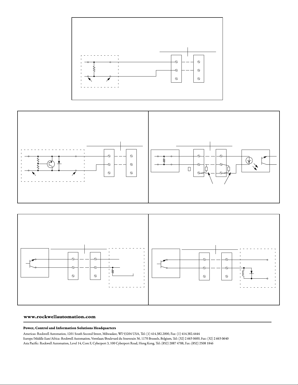
#63--66 OR #63--64 CONTROL TERMINAL CONNECTIONS
CONTROL TERMINALS
TYPES 13, 22 & 23 TYPE 42RL
-- ( A )
(9) --
17 VDC MIN.
+(B) (6)+
BASE PINS
#63-- 67 OR #63--65
CONTROL TERMINAL CONNECTIONS
CONTROL TERMINALS
TYPES 13, 22 & 23 TYPE 42RL
(A) --
-- ( 7 )
(B) + + (4)
BASE PINS
CAUTION: CUSTOMER POWER SUPPLY MUST NEVER BE DIRECTLY CONNECTED
ACROSS OPEN COLLECTOR TERMINALS.
2C
2NO
2NC
1C
1NO
1NC
1C
1NO
1NC
-- ( A ) (9) --
+(B) (6)+
#63--66
#63--64
2C
2NO
2NC
#63-- 66 OR #63--64
TYPICAL INTERFACING
CONTROL TERMINALS
TYPES 13, 22 & 23 TYPE 42RL
1C
1NO
1NC
1K Ω, 1W for 20 Ma. Min.
560 Ω, 2W for 30 Ma. Min.
2C
2NO
2NC
RESISTOR
17 VDC
MIN.
OPTO-ISOLATOR
INTERFACE
#63-- 67 OR #63--65
TYPICAL LOGIC INTERFACING
CONTROL TERMINALS
TYPES 13, 22 & 23 TYPE 42RL
(7) --
(4)+
#63--67
#63--65
2C
2NO
2NC
Publication PA--9207(A)
November 1992
Supercedes Publication PA--8202
1C
1NO
1NC
--
LOGIC INPUT
+
PULL UP
RESISTOR
+5V (U P TO 30
VDC MAX.)
CUSTOMER LOGIC
TTL,R TL, DTL,CMOS
(7) --
(4)+
#63--67
#63--65
TYPICAL COUNTER INTERFACING
#63-- 67 OR #63--65
CONTROL TERMINALS
TYPES 13, 22 & 23 TYPE 42RL
2C
2NO
2NC
1C
1NO
1NC
UP TO 24 VDC MAX.
250 MA MAX. CURRENT
CUSTOMER ELECTRO
MECHANICAL COUNTER
--
+
 Loading...