

Page 1
Installation Instructions
Original Instructions
VersaView 6300 DC Connector Assemblies and
Replacement Mounting Clips
Catalog Numbers 6300V-DCCONN, 6300V-DCCONN2, 6300V-DCCONN3, 6300V-MTGCLIP16
Topic Page
Required Tools for Installation 1
Install a DC Connector Assembly 1
Install the Replacement Mounting Clips 3
The instructions in this publication apply to the following items:
• A connector assembly for DC-powered VersaView® 6300 PCs and VersaView 6300 monitors
• Replacement mounting clips for VersaView 6300P panel PCs and VersaView 6300M monitors
Required Tools for Installation
The following tools are to install a 6300V-DCCONN, 6300V-DCCONN2, or 6300V-DCCONN3 DC connector assembly:
• Adjustable torque screwdriver with metric flat-blade screw bits
• Wire stripper, cutter, and crimper tool
•Cutting pliers
• Safety glasses
The following tools are to install the replacement 6300V-MTGCLIP16 mounting clips:
• 1.5 mm hex key (two are supplied with the mounting clips)
• Adjustable torque driver with 1.5 mm hex key bit
• Safety glasses
Install a DC Connector Assembly
The connector assembly provides strain relief for the DC power wires by reducing their movement. To assemble and
attach the connector assembly, perform the following steps.
IMPORTANT
1. Disconnect power to the computer.
2. Remove the DC terminal block from the computer chassis.
3. Open the power connector assembly kit that ships with the computer (A in Figure 2 on page 3
4. Insert the cable tie through the slots of the appropriate connector half (B in Figure 2 on page 3
5. Strip the end of each DC power wire to the length in Figure 1 on page 2
6. Insert each stripped end into the DC terminal block as shown in Figure 1
DC power wires must be of stranded copper and sized according to Figure 1 on page 2.
).
).
.
.
Page 2
VersaView 6300 DC Connector Assemblies and Replacement Mounting Clips Installation Instructions
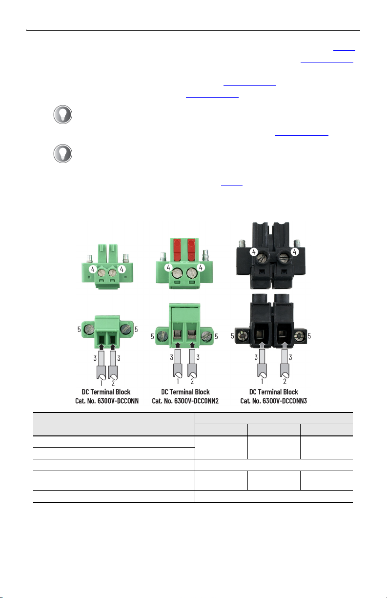
Item Description
Attribute
6300V-DCCONN 6200V-DCCONN2 6300V-DCCONN3
1 DC+ (24V DC nominal) recommended power wire size
1.5 mm
2
(16 AWG) 2.5 mm2 (14 AWG) 4 mm2 (12 AWG)
2DC- (0V DC) recommended power wire size
3 Stripped wire length 7 mm (0.275 in.)
4 Torque range to secure DC power wires
0.22...0.25 N•m
(0.16...0.18 ft•lb)
0.5...0.6 N•m
(0.37...0.44 ft•lb)
0.4...0.5 N•m
(0.3...0.37 ft•lb)
5 Torque value to reinstall DC terminal block to computer 0.5...0.6 N•m (0.37...0.44 ft•lb)
7. Tighten the screws on top of the terminal block to secure the DC power wires to the torque value in Figure 1.
8. Slide the connector half with the attached tie onto the end of the DC terminal block (C in Figure 2 on page 3
9. Tighten the cable tie so it is snug against the terminal wires.
10. Use cutting pliers to cut the excess part of the cable tie (D in Figure 2 on page 3
11. Install the white label supplied with the kit (E in Figure 2 on page 3
).
).
The white label can be used for identification or other information.
).
12. Align and install the other connector clamp half to complete the assembly (F in Figure 2 on page 3
When installed correctly, both tabs of the clamp half lock into place.
13. Reconnect the DC terminal block with the connector assembly to the computer chassis.
Torque the DC terminal block flange screws to the values in Figure 1.
14. Turn on the main power switch or breaker.
Figure 1 - DC Terminal Block Connection Specifications
).
2 Rockwell Automation Publication 6300V-IN003A-EN-P - January 2021
Page 3

VersaView 6300 DC Connector Assemblies and Replacement Mounting Clips Installation Instructions
DA B C E F
Figure 2 - DC Connector Assembly Sequence
IMPORTANT
The DC connector assembly that is shown in Figure 2 is only for illustrative purposes. Your
DC connector assembly can differ in size, shape, and color to what is shown in Figure 2.
Install the Replacement Mounting Clips
To replace mounting clips on VersaView 6300P panel PCs and 6300M monitors, perform the following steps.
1. Disconnect power to the computer or monitor.
2. Slide the replacement mounting clips into the holes on the
sides of the computer or monitor as shown at right. For the
various hole locations, see Figure 3 on page 4
3. Hand-tighten the mounting clips according to the tighten
sequence in Figure 3 on page 4
4. With the supplied 1.5 mm hex key, tighten the mounting clips
to the tighten sequence in Figure 3 on page 4
5. With the adjustable torque driver and 1.5 mm hex key bit, tighten the mounting clips to a torque of 0.2 N•m
(1.8 lb•in) by the tighten sequence in Figure 3 on page 4
6. Repeat this process at least three times until the clips are torqued properly to 0.2 N•m (1.8 lb•in).
Verify that the gasket is compressed uniformly against the panel.
ATTENTION: Tighten the mounting clips to the specified torque to provide a proper
seal and to help prevent product damage. Rockwell Automation assumes no
responsibility for water or chemical damage to the computer or other equipment within
the enclosure because of improper installation.
.
.
.
.
Rockwell Automation Publication 6300V-IN003A-EN-P - January 2021 3
Page 4

*PN-618253*
PN-618253
Figure 3 - Tighten and Torque Sequence for the Mounting Clips
I/O Ports
18
72
4
5
6
3
8.4…15 in., and 17 in. Display Sizes
I/O Ports
10 1
62
3
8
7
4
9
5
15.6 in. and 19 in. Display Sizes
I/O Ports
18.5 in. Display Size
10 1
62
8
4
9
5
7
12
3
11
I/O Ports
21.5 in. and 24 in. Display Sizes
10 1
62
3
8
14
4
9
5
7
12
13
11
Waste Electrical and Electronic Equipment (WEEE)
At the end of life, this equipment should be collected separately from any unsorted
municipal waste.
Rockwell Automation maintains current product environmental compliance information on its website at rok.auto/pec.
Your comments help us serve your documentation needs better. If you have any suggestions on how to improve our content, complete the
form a t rok.auto/docfeedback.
For technical support, visit rok.auto/support.
Rockwell Otomasyon Ticaret A.Ş. Kar Plaza İş Merkezi E Blok Kat:6 34752, İçerenköy, İstanbul, Tel: +90 (216) 5698400
EEE Yönetmeliğine Uygundur
Allen-Bradley, expanding human possibility, Rockwell Automation, and VersaView are trademarks of Rockwell Automation, Inc.
Trademarks not belonging to Rockwell Automation are property of their respective companies.
Publication 6300V-IN003A-EN-P - January 2021 | Supersedes Publication XXXX-X.X.X - Month Year
Copyright © 2021 Rock well Automation, Inc. All rights reserved. Printed in Italy.
Vendor Code 80460052.00
DIR 10005949197 (Version 00)
 Loading...