

Page 1

Digital Output Accessory
Catalog Number 6189V-OB36
Inside...
English....................................................... 3
Français..................................................... 9
Deutsch................................................... 15
Italiano.................................................... 21
Español.................................................... 27
Português................................................ 35
Installation Instructions
Publication 6180W-IN003B-MU-P
Page 2
2 Digital Output Accessory
Important User Information
Solid state equipment has operational characteristics differing from those of electromechanical equipment.
Safety Guidelines for the Application, Installation and Maintenance of Solid State Controls (Publication
SGI-1.1 available from your local Rockwell Automation sales office or online at
http://www.ab.com/manuals/gi) describes some important differences between solid state equipment and
hard-wired electromechanical devices. Because of this difference, and also because of the wide variety of
uses for solid state equipment, all persons responsible for applying this equipment must satisfy themselves
that each intended application of this equipment is acceptable.
In no event will Rockwell Automation, Inc. be responsible or liable for indirect or consequential damages
resulting from the use or application of this equipment.
The examples and diagrams in this manual are included solely for illustrative purposes. Because of the many
variables and requirements associated with any particular installation, Rockwell Automation, Inc. cannot
assume responsibility or liability for actual use based on the examples and diagrams.
No patent liability is assumed by Rockwell Automation, Inc. with respect to use of information, circuits,
equipment, or software described in this manual.
Reproduction of the contents of this manual, in whole or in part, without written permission of Rockwell
Automation, Inc. is prohibited.
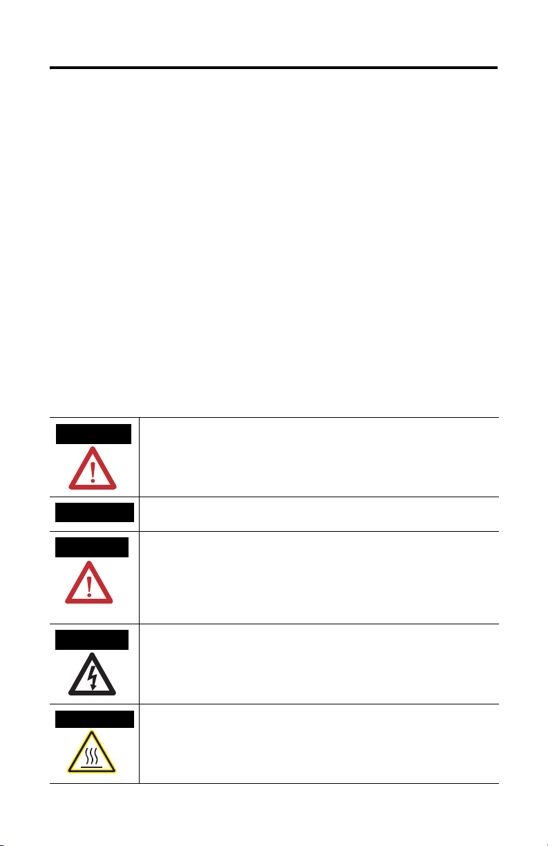
Throughout this manual we use notes to make you aware of safety considerations.
WARNING
Identifies information about practices or circumstances that can cause an explosion in a
hazardous environment, which may lead to personal injury or death, property damage,
or economic loss.
IMPORTANT
ATTENTION
SHOCK HAZARD
BURN HAZARD
Identifies information that is critical for successful application and understanding of the
product.
Identifies information about practices or circumstances that can lead to personal injury
or death, property damage, or economic loss. Attentions help you:
• identify a hazard
• avoid a hazard
• recognize the consequence
Labels may be located on or inside the drive to alert people that dangerous voltage may
be present.
Labels may be located on or inside the drive to alert people that surfaces may be
dangerous temperatures.
Publication 6180W-IN003B-MU-P
Page 3

Installation Instructions
Digital Output Accessory
Catalog Number 6189V-OB36
English
The 6189V-OB36 Digital Accessory Kit provides 36 solid state outputs to signal the
state of a subset of the keys on the bezel of the VersaView 1200W (catalog number
6180W-12XXXXX) computer. The Digital Output Accessory works with all Series B
and later revisions of the 1200W computer.
When a key on the bezel of the 1200W computer is pressed, the keystroke is
received by the operating system and/or by application software that is running on
the computer. This normal key function is not affected by the installation or
removal of the Digital Output Accessory. The Digital Output Accessory provides an
additional electrical signaling function for keys on the bezel that are classified as
special function keys (A1 to A8, F1 to F20, K1 to K8). When the Digital Output
Accessory is installed, keystrokes of the special function keys are sent to both the
operating system and the output accessory. The accessory has outputs that are
dedicated to signal the state of the special function keys.
This document provides instructions on how to install and use the Digital Output
Accessory with the 1200W computer.
Contents of Kit
The following items are included with the Digital Output Accessory Kit:
• Digital Output Module
• (4) Mounting Screws
• Installation Instructions
Required Tools
The only tool required for installation is the #2 Phillips screwdriver.
Publication 6180W-IN003B-MU-P
Page 4
4 Digital Output Accessory
Precautions
Before installing or replacing the components, remove the power from the
computer. During installation, take care not to touch any of the exposed electronic
components.
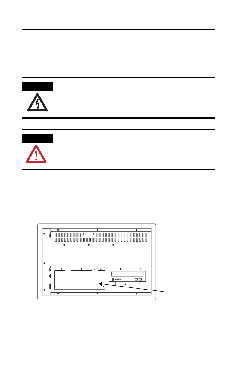
SHOCK HAZARD
ATTENTION
Remove power from the computer before installing or replacing
components. Failure to disconnect power may result in electrical
shock and/or damage to the computer.
Electrostatic Discharge (ESD) can damage the computer and
components. Work in a static-free environment and wear a
grounding strap whenever handling circuit boards, power supply,
memory modules, or other internal components.
Install the Digital Output Accessory
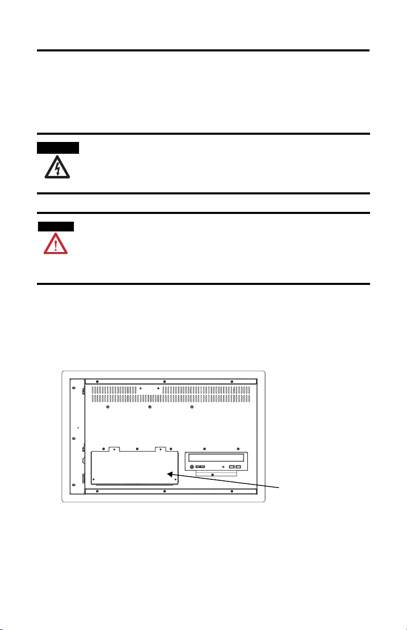
1. Remove the 4 screws that secure the rectangular cover on the lower left rear
of the 1200W chassis. Remove the cover plate and set the screws aside for
later use.
Cover with 4 Screws
2. Inside the opening, a 40-pin conductor ribbon cable is held in place by
plastic retainer clips. Detach the cable from its retainer clips. Extend the
cable out through rear opening in the chassis.
Publication 6180W-IN003B-MU-P
Page 5
Digital Output Accessory 5
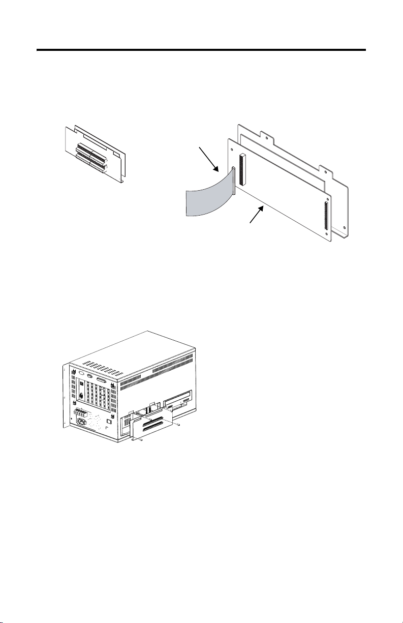
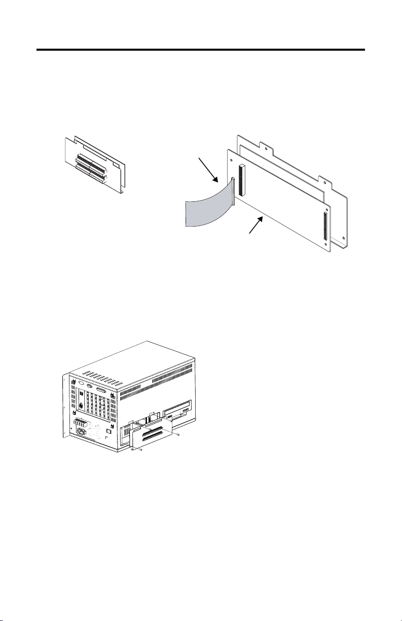
3. Connect the ribbon cable to the mating 40-pin connector that is on the
printed circuit board of the Digital Output Accessory. The connector is
keyed for proper alignment. Make sure the connector is firmly seated.
Ribbon Cable removed
from inside of unit.
Digital Output Board and Cover
Digital Output Accessory
4. Carefully fold the ribbon cable back into the chassis of the 1200W. Secure
the cable with the retaining clips from which it was removed. Be careful not
to pinch the cable as the Digital Output Accessory is placed into the opening
at the rear of the chassis. Secure the Digital Output Accessory to the chassis
with the screws that were removed in Step 1.
Publication 6180W-IN003B-MU-P
Page 6

6 Digital Output Accessory
Connect the Digital Outputs
Loads are connected to the digital outputs by means of two 20-point removable
terminal blocks. The terminal blocks are provided as part of the output module.
Each of the terminal blocks consist of a fixed (header) part, and a removable (plug)
part. The screws at either end of the terminal block can be backed out to release
the terminal plug for ease of connection. The terminals support wire sizes from
AWG 24 to AWG 14.
Before using the digital outputs it is necessary to connect your load(s) and a (user
supplied) external DC power supply. The DC power supply is used to energize the
loads.
1. Connect the two leads of the DC power supply (in the range of 10 to 50
volts DC) to the terminals labeled +VDC and DC COM.
2. Connect the positive output of the supply to either or both of the +VDC
terminals, they are internally connected.
3. Connect the common connection of the power supply to either or both of
the DC COM terminals, they are internally connected.
The locations of the terminals of the digital output accessory are shown in the
terminal diagram below.
K1 K2 K3
A1
A2
K4 K5 K6 K7 K8
A3
A4 A5 A6 A7 A8
F1 F2
F11 F12F3F13F4F14
F5
F6
F15
F16F7F17F8F18F9F19
F10
F20
+VDC
+VDC
DC
COM
DC
COM
You can connect loads to as few as 1, or to as many as 36 of the outputs. Each load
must fall within the range given in the output specifications table. The terminal
diagram above shows the relationship between the output terminals and the special
function keys of the 1200W keypad.
The digital outputs source current to connected loads. The positive terminal of a
polarized load should be connected to the output terminal. The negative terminal
of the load should be connected to the DC common connection of the power
supply.
Publication 6180W-IN003B-MU-P
Page 7
Digital Output Accessory 7
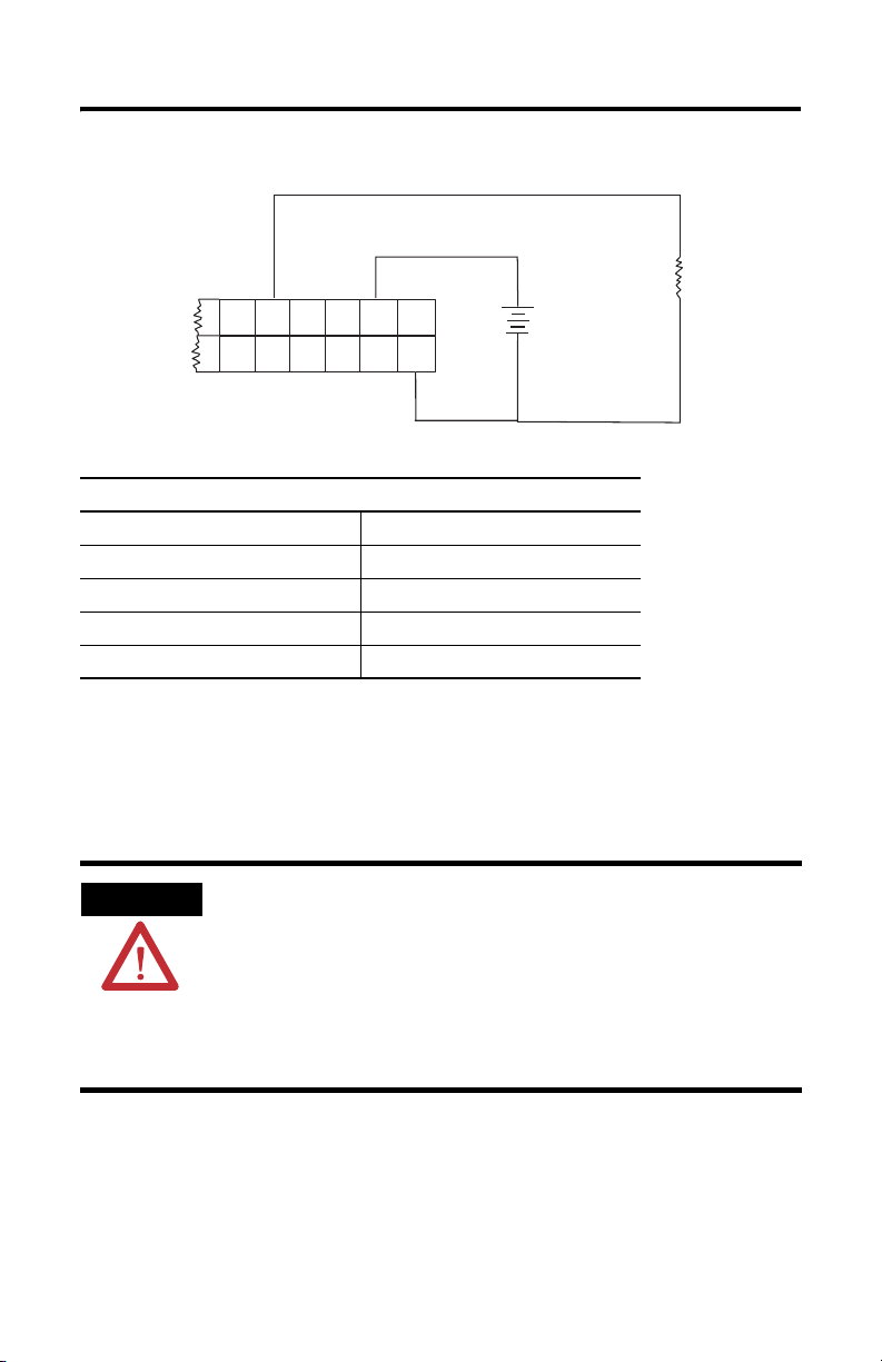
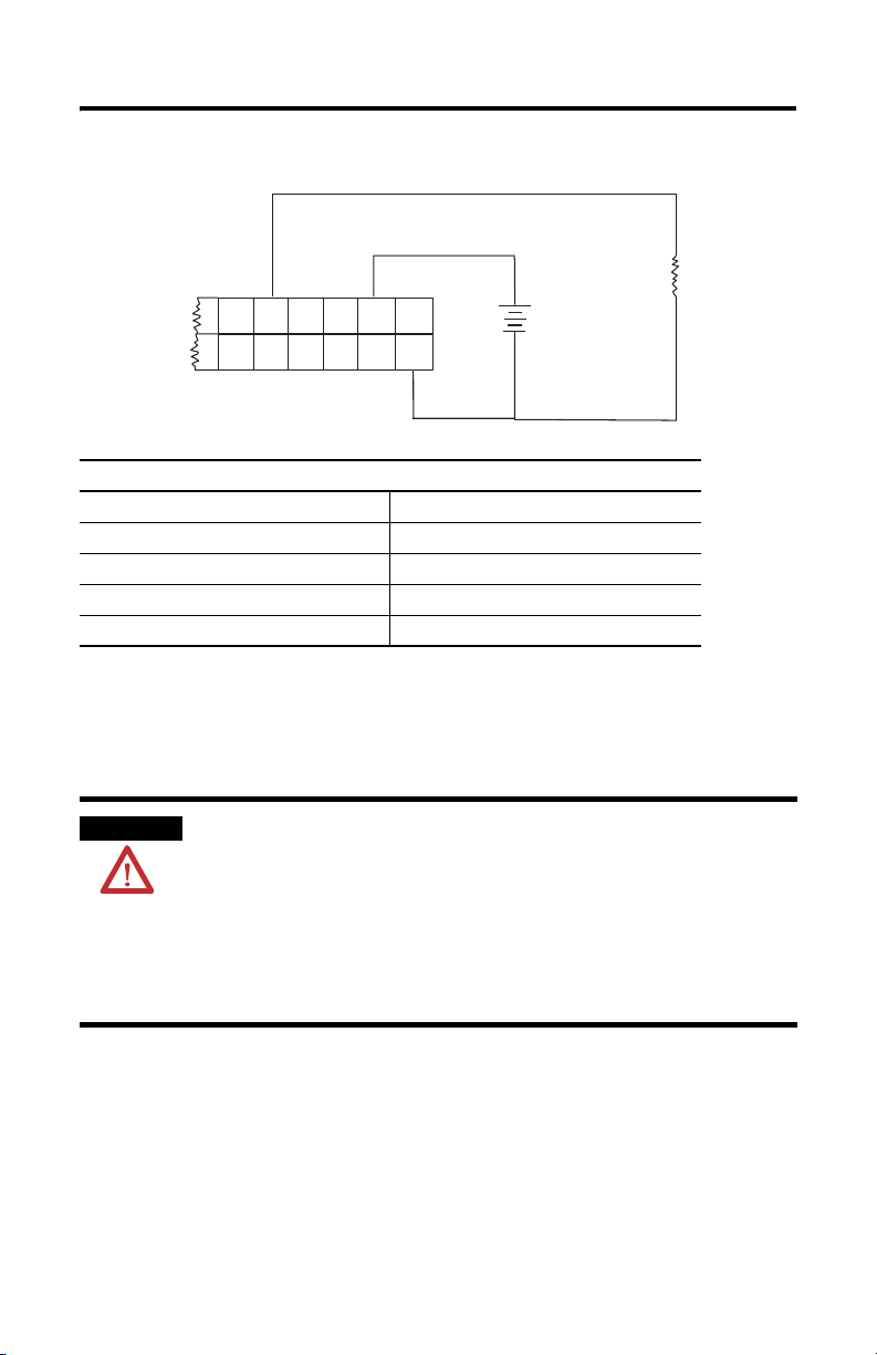
The following diagram shows a typical load connection at digital output F8.
+
Load
F7
F17F8F18F9F19
Output Specifications
Operating Voltage Range 10…50 V dc
Off-State Leakage Current (per point) 1 mA (maximum)
Minimum Load Current (per point) 1 mA
Maximum Load Current (per point) 0.25 A
On-State Voltage Drop 1.2V dc @ 0.25 A
F10
F20
+VDC
+VDC
DC
COM
DC
COM
+
-
DC
Supply
-
Output Operation
An output that is connected to the terminal block will be energized when its
corresponding key is pressed on the keypad at the front of the 1200W workstation.
WARNING
The keys on the bezel of the 1200W are momentary push button switches. Any key
press energizes its corresponding output only while the key is pressed. Although
the keys of the bezel have a snap-action tactile feedback, this feedback is not a
foolproof indicator of electrical contact. It is possible to make and break the
electrical contact without a tactile sense of the change of state. Ensure that the
application is designed in such a way that the load is not sensitive to rapid
make/break operation of the bezel keys.
The digital outputs are not under any form of software control. If
a load and a power supply are connected to the digital output accessory, the load will be energized whenever its corresponding
key on the bezel of the 1200W is pressed. The output function is
disabled only by disconnecting the wiring from the accessory.
Make certain that the installation provides appropriate safeguards
to prevent accidental or unintentional operation of the loads connected to the accessory.
Publication 6180W-IN003B-MU-P
Page 8
8 Digital Output Accessory
0
1
0
0
0
0
0
0
0
0
0
300200100
1
ATTENTION
A brief transient current pulse may flow through the digital
outputs if the external supply voltage is suddenly connected to
the +VDC or the DC COM terminal (for example through a relay
or other hard-contact switch). It is the fast rate of change of
voltage at the terminals that causes the pulse. This condition is
inherent in transistor outputs and is common to solid state
devices. The transient pulses may occur whether the 1200W
computer is running or not, and without regard to the status of
the keys of the 1200W keypad.
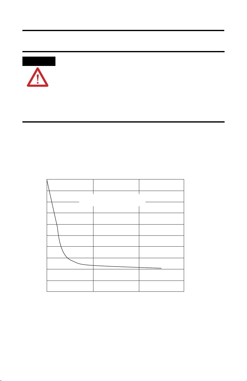
The transient energy is dissipated in the load, and the pulse duration is longer for
loads of high impedance. The graph below illustrates the relation between pulse
duration and load current. Transient pulse duration will not exceed the time shown
in the graph. For most applications, the pulse energy is not sufficient to energize
the load.
.0
.9
.8
.7
.6
.5
Function of Load Current
Transient Pulse Duration as a
.4
.3
Time Duration of Transient (ms)
.2
.1
.0
On-State Load Current (mA)
The recommended wiring method is to connect the external supply directly to the
+VDC and DC COM terminals. The voltage rate of change is then limited by the
power up characteristics of the supply, and the stray transient pulses may be
avoided.
Publication 6180W-IN003B-MU-P
Page 9

Notice d’installation
Carte de sorties TOR pour stations industrielles
VersaView 1200 W
Référence 6189V-OB36
Français
La carte de sorties TOR 6189V-OB36 offre 36 sorties statiques indiquant l’état d’un
ensemble de touches figurant sur la face avant de la station industrielle
VersaView 1200 W (réf. 6180 W-12XXXXX). Elle fonctionne avec toutes les
stations 1200 W série B et de révision ultérieure.
Lorsque vous appuyez sur une touche de la face avant de la station 1200 W,
l’information est reçue par le système d’exploitation et/ou par le logiciel
d’application tournant sur la station. L’installation ou le retrait de la carte de sorties
TOR n’affecte pas ce fonctionnement normal de la touche. Cette carte offre une
fonction de signalisation électrique supplémentaire pour les touches de fonction
spéciales de la face avant (A1 à A8, F1 à F20, K1 à K8). Lorsque la carte de sorties
TOR est installée, chaque fois que vous appuyez sur l’une de ces touches de
fonction spéciales, l’information est transmise à la fois au système d’exploitation et
à la carte. Cette carte comporte des sorties qui sont réservées à la signalisation de
l’état des touches de fonction spéciales.
La présente notice indique comment installer et utiliser la carte de sorties TOR avec
la station industrielle 1200 W.
Contenu du kit
Le kit comprend les éléments suivants :
• la carte de sorties TOR ;
• 4 vis de fixation ;
• une notice d’installation.
Outils nécessaires
Le seul outil nécessaire pour l’installation est un tournevis Phillips n° 2.
Publication 6180W-IN003B-MU-P
Page 10
10 Carte de sorties TOR pour stations industrielles VersaView 1200 W
Précautions
Avant d’installer ou de remplacer des composants, déconnectez l’alimentation de la
station. Pendant l’installation, veillez à ne pas toucher les composants électroniques
exposés.
DANGER
D’ELECTROCUT ION
Avant d’installer ou de remplacer des composants, déconnectez
l’alimentation de la station. En cas de non-respect de cette
consigne, vous risquez de vous électrocuter ou d’endommager la
station.
ATTENTION
Les décharges électrostatiques peuvent endommager la station et
ses composants. Travaillez dans un environnement exempt
d’électricité statique et portez un bracelet antistatique lorsque
vous manipulez les cartes de circuits imprimés, l’alimentation, les
modules mémoire ou tout autre composant interne.
Installation de la carte de sorties TOR
1. Retirez les 4 vis qui maintiennent la plaque rectangulaire située à l’arrière du
châssis de la station 1200 W, dans l’angle inférieur gauche. Retirez la plaque
et mettez les vis de côté : vous les réutiliserez plus tard.
Plaque avec 4 vis
2. Dans cette ouverture, un câble plat à 40 broches est maintenu par des clips
de fixation en plastique. Dégagez le câble de ses clips de fixation.
Déroulez-le hors de l’ouverture du châssis.
Publication 6180W-IN003B-MU-P
Page 11
Carte de sorties TOR pour stations industrielles VersaView 1200 W 11
3. Branchez le câble plat sur le connecteur à 40 broches correspondant, sur le
circuit imprimé de la carte de sorties TOR. Le connecteur est détrompé pour
permettre un alignement correct. Assurez-vous que le connecteur est bien
inséré.
Câble plat extrait de la station
Carte de sorties TOR avec couvercle
Carte de sorties TOR
4. Repliez soigneusement le câble plat à l’intérieur du châssis de la
station 1200 W. Remettez ses clips de fixation en place. Veillez à ne pas
pincer le câble en plaçant la carte de sorties TOR dans l’ouverture à l’arrière
du châssis. Fixez le module de sorties TOR sur le châssis à l’aide des vis que
vous avez retirées à l’étape 1.
Publication 6180W-IN003B-MU-P
Page 12

12 Carte de sorties TOR pour stations industrielles VersaView 1200 W
Connexion des sorties TOR
Les charges sont connectées aux sorties TOR par deux borniers débrochables à
20 broches. Les borniers sont fournis avec la carte de sorties. Chaque bornier est
constitué d’une partie fixe (embase) et d’une partie amovible (fiche). Vous pouvez
retirer les vis situées à chaque extrémité du bornier pour libérer la partie amovible
et faciliter la connexion. Les bornes acceptent des câbles de calibre 24 à 14 AWG
(0,2 à 2 mm
Avant d’utiliser les sorties TOR, vous devez connecter votre ou vos charge(s) et une
alimentation c.c. externe (fournie par l’utilisateur). L’alimentation c.c. sert à
alimenter les charges.
1. Connectez les deux fils de l’alimentation c.c. (entre 10 et 50 V c.c.) aux
2. Connectez la sortie positive de l’alimentation à l’une ou aux deux bornes
3. Connectez le commun de l’alimentation à l’une ou aux deux bornes
L’emplacement des bornes de la carte de sorties TOR est indiqué sur le schéma
suivant.
2
).
bornes +VDC et DC COM.
+VDC : elles sont connectées en interne.
DC COM : elles sont connectées en interne.
K1 K2 K3
A1
A2
K4 K5 K6 K7 K8
A3
A4 A5 A6 A7 A8
F1 F2
F11 F12F3F13F4F14
F5
F6
F15
F16F7F17F8F18F9F19
F10
F20
+VDC
+VDC
DC
COM
DC
COM
Vous pouvez connecter des charges à une seule sortie ou aux 36 sorties. Chaque
charge doit figurer dans la plage indiquée dans le tableau de spécifications des
sorties. Le schéma de brochage ci-dessus montre la relation entre les bornes des
sorties et les touches de fonction spéciales du clavier de la station 1200 W.
Les sorties TOR fournissent le courant aux charges connectées. La borne positive
d’une charge polarisée doit être connectée à la borne de sortie. La borne négative
de la charge doit être connectée au commun c.c. de l’alimentation.
Publication 6180W-IN003B-MU-P
Page 13
Carte de sorties TOR pour stations industrielles VersaView 1200 W 13
Le schéma suivant montre une connexion type à la sortie TOR F8.
+
F7
F17F8F18F9F19
Caractéristiques des sorties
Plage de tensions de fonctionnement 10 à 50 V c.c.
Courant de fuite de désactivation (par point) 1 mA (maximum)
Courant de charge minimal (par point) 1 mA
Courant de charge maximal (par point) 0,25 A
Chute de tension en charge 1,2 V c.c. sous 0,25 A
F10
F20
+VDC
+VDC
DC
COM
DC
COM
DC
Alimentation c.c.
Supply
-
Fonctionnement des sorties
+
Charge
-
Load
Une sortie connectée au bornier est alimentée lorsque vous appuyez sur la touche
correspondante du clavier située sur la face avant de la station 1200 W.
AVERTISSEMENT
Les sorties TOR ne font l’objet d’aucune commande logicielle. Si
une charge et une alimentation sont connectées à la carte de sorties
TOR, la charge sera alimentée lorsque vous appuierez sur la touche
correspondante de la face avant de la station 1200 W. La sortie
n’est désactivée que par la déconnexion de la carte. Veillez à ce
que l’installation fournisse tous les dispositifs de protection qui
conviennent pour empêcher tout fonctionnement inopiné des
charges connectées à la carte.
Les touches située sur la face avant de la station 1200 W sont des commutateurs à
bouton-poussoir à impulsions. Le fait d’appuyer sur une touche active la sortie
correspondante uniquement pendant que la touche est enfoncée. Bien que les
touches de la face avant aient une réponse tactile instantanée, cette réponse n’est
pas une preuve absolue qu’un contact électrique est établi. Il est possible de fermer
et d’ouvrir le contact électrique sans perception tangible du changement d’état.
Veillez à ce que l’application soit conçue de façon à ce que la charge ne soit pas
sensible aux rapides fermetures/ouvertures des contacts des touches de la face
avant.
Publication 6180W-IN003B-MU-P
Page 14

14 Carte de sorties TOR pour stations industrielles VersaView 1200 W
0
1
0
0
0
0
0
0
0
0
0
300200100
1
ATTENTION
Une brève impulsion transitoire peut circuler via les sorties TOR si
l’alimentation externe est soudainement connectée à la borne
+VDC ou DC COM (par un relais ou par tout autre commutateur à
contact sec par exemple). C’est le changement rapide de tension
au niveau des bornes qui génère cette impulsion. Cette condition
est inhérente aux sorties transistor et commune sur les dispositifs
statiques. Les impulsions transitoires peuvent se produire que la
station 1200 W fonctionne ou non, et quel que soit l’état des
touches de son clavier.
L’énergie transitoire est dissipée dans la charge et la durée de l’impulsion est plus
longue pour les charges à forte impédance. Le graphique ci-dessous montre que la
durée de l’impulsion est inversement proportionnelle au courant de charge. La
durée de l’impulsion transitoire ne dépassera pas la durée indiquée dans le
graphique. Pour la plupart des applications, l’énergie de l’impulsion n’est pas
suffisante pour activer la charge.
.0
.9
.8
.7
.6
.5
en fonction du courant de charge
Durée d’une impulsion transitoire
.4
.3
Durée de l’impulsion transitoire (ms)
.2
.1
.0
Courant de charge d’activation (mA)
Pour le câblage, il est recommandé de connecter l’alimentation externe directement
aux bornes +VDC et DC COM. La vitesse de variation de la tension est alors limitée
par les caractéristiques de mise sous tension de l’alimentation : les impulsions
transitoires parasites peuvent ainsi être évitées.
Publication 6180W-IN003B-MU-P
Page 15

Installationsanleitung
Digitalausgangserweiterung
Bestellnummer 6189V-OB36
Deutsch
Das Digitalausgangserweiterungs-Kit 6189V-OB36 bietet 36 Halbleiterausgänge, die
den Status einiger Tasten von der Frontblende des VersaView-Computers 1200W
anzeigen (Bestellnummer 6180W-12XXXXX). Die Digitalausgangserweiterung kann
mit allen 1200W-Computern der Serie B und aktuelleren Versionen eingesetzt
werden.
Beim Drücken einer Taste auf der Frontblende des 1200W-Computers wird das
Signal vom Betriebssystem und/oder der auf dem Computer ausgeführten
Anwendungssoftware empfangen. Die Installation oder das Entfernen der
Digitalausgangserweiterung hat keinen Einfluss auf diese normale Tastenfunktion.
Die Digitalausgangserweiterung bietet eine zusätzliche elektrische Signalfunktion
für Tasten auf der Frontblende, die für spezielle Funktionen vorgesehen sind (A1
bis A8, F1 bis F20, K1 bis K8). Nach der Installation der Digitalausgangserweiterung
werden die Tastensignale beim Drücken der Funktionstasten an das Betriebssystem
und die Ausgangserweiterung gesendet. Die Ausgangserweiterung verfügt über
Ausgänge, deren Aufgabe es ist, den Status der Funktionstasten zu signalisieren.
Dieses Dokument enthält Anweisungen zur Installation und Verwendung der
Digitalausgangserweiterung mit dem 1200W-Computer.
Inhalt des Kits
Das Digitalausgangserweiterungs-Kit enthält folgende Produkte:
• Digitales Ausgangsmodul
• (4) Montageschrauben
• Installationsanleitung
Erforderliche Werkzeuge
Für die Installation ist nur ein Kreuzschlitz-Schraubendreher (#2) erforderlich.
Publikation 6180W-IN003B-MU-P
Page 16

16 Digitalausgangserweiterung
Vorsichtsmaßnahmen
Unterbrechen Sie vor der Installation oder dem Austausch von Komponenten die
Stromversorgung des Computers. Berühren Sie während der Installation keine frei
liegenden elektronischen Komponenten.
STROMSCHLAGGEFAHR
ACHTUNG
Unterbrechen Sie vor der Installation oder dem Austausch von
Komponenten die Stromversorgung des Computers. Wird die
Stromversorgung nicht unterbrochen, kann dies zu Stromschlägen
und/oder zur Beschädigung des Computers führen.
Eine elektrostatische Entladung kann zur Beschädigung des
Computers und der Komponenten führen. Achten Sie darauf, dass
die Umgebung, in der Sie arbeiten, keine elektrostatische Ladung
aufweist, und tragen Sie in jedem Fall ein Erdungsband, wenn Sie
Leiterplatten, das Netzteil, Speichermodule oder andere interne
Komponenten berühren müssen.
Installation der Digitalausgangserweiterung
1. Entfernen Sie die vier Schrauben, mit denen die rechteckige Abdeckung
rechts hinten am 1200W-Chassis befestigt ist. Nehmen Sie die Abdeckplatte
ab, und legen Sie die Schrauben zur späteren Verwendung zur Seite.
Abdeckung mit vier
Schrauben
2. In der Öffnung ist ein 40-poliges Flachkabel mit Befestigungslaschen aus
Kunststoff fixiert. Lösen Sie das Kabel von den Befestigungslaschen. Ziehen
Sie das Kabel durch die rückwärtige Chassis-Öffnung heraus.
Publikation 6180W-IN003B-MU-P
Page 17

Digitalausgangserweiterung 17
3. Schließen Sie das Flachkabel am passenden 40-poligen Steckverbinder auf
der Leiterplatte der Digitalausgangserweiterung an. Die Beschaffenheit des
Steckverbinders ermöglicht einen fehlerfreien Anschluss. Vergewissern Sie
sich, dass das Kabel fest sitzt.
Aus der Einheit
herausgeführtes
Flachkabel.
Platine und Abdeckung des
digitalen Ausgangs
Digitalausgangserweiterung
4. Führen Sie das Flachkabel vorsichtig wieder in das Gehäuse des
1200W-Computers ein. Fixieren Sie das Kabel mit den Befestigungslaschen,
die Sie zuvor gelöst haben. Achten Sie darauf, dass Sie das Kabel beim
Einführen der Digitalausgangserweiterung in die Öffnung auf der Rückseite
des Gehäuses nicht abklemmen. Befestigen Sie die
Digitalausgangserweiterung mit den in Schritt 1 entfernten Schrauben am
Chassis.
Publikation 6180W-IN003B-MU-P
Page 18

18 Digitalausgangserweiterung
Anschließen der digitalen Ausgänge
Die Lasten werden an den digitalen Ausgängen mit Hilfe zweier abnehmbarer
20-Punkt-Klemmenleisten angeschlossen. Die Klemmenleisten sind im Lieferumfang
des Ausgangsmoduls enthalten. Jede Klemmenleiste besteht aus einem festen und
einem abnehmbaren Teil. Die Schrauben an beiden Enden der Klemmenleiste
können nach hinten herausgezogen werden, um den einfacheren Anschluss zu
ermöglichen. Die Klemmen unterstützen Drahtstärken von AWG 24 (0,2 mm²) bis
AWG 14 (2,5 mm²).
Vor der Verwendung der digitalen Ausgänge müssen Sie Ihre Last(en) und ein (vom
Anwender bereitgestelltes) DC-Netzteil anschließen. Das DC-Netzteil dient zum
Anlegen von Spannung an die Lasten.
1. Schließen Sie die beiden Leitungen des Netzteils (im Bereich zwischen 10
und 50 Volt Gleichstrom) an die Klemmen an, die mit +VDC und DC COM
gekennzeichnet sind.
2. Schießen Sie den positiven Ausgang des Netzteils an eine oder an beide
+VDC-Klemmen an (diese sind intern miteinander verbunden).
3. Schließen Sie den Bezugspotenzial-Anschluss des Netzteils an eine oder an
beide DC-COM-Klemmen an (diese sind intern verbunden).
Die Positionen der Klemmen der Digitalausgangserweiterung sind im
nachfolgenden Klemmendiagramm aufgezeigt.
K1 K2 K3
A1
A2
K4 K5 K6 K7 K8
A3
A4 A5 A6 A7 A8
F1 F2
F11 F12F3F13F4F14
F5
F6
F15
F16F7F17F8F18F9F19
F10
F20
+VDC
+VDC
DC
COM
DC
COM
Sie können Lasten nur an einen Ausgang oder an bis zu 36 Ausgänge anschließen.
Jede Last muss innerhalb des Bereichs liegen, der in der Tabelle mit den
Ausgangsspezifikationen angegeben ist. Das oben angeführte Klemmendiagramm
zeigt die Beziehung zwischen den Ausgangsklemmen und den Funktionstasten der
1200W-Tastatur.
Die digitalen Ausgänge liefern Strom an die angeschlossenen Lasten. Die positive
Klemme einer polarisierten Last muss an die Ausgangsklemme angeschlossen
werden. Die negative Klemme der Last muss an den DC-Bezugspotenzial-Anschluss
des Netzteils angeschlossen werden.
Publikation 6180W-IN003B-MU-P
Page 19

Digitalausgangserweiterung 19
Das folgende Diagramm zeigt einen typischen Lastanschluss am digitalen
Ausgang F8.
+
F7
F17F8F18F9F19
Ausgangsspezifikationen
Betriebsspannungsbereich 10–50 V DC
Leckstrom im AUS-Zustand (je Punkt) 1 mA (maximal)
Minimaler Laststrom (je Punkt) 1 mA
Maximaler Laststrom (je Punkt) 0,25 A
Spannungsabfall im EIN-Zustand 1,2 V DC bei 0,25 A
F10
F20
+VDC
+VDC
DC
COM
DC
COM
+
-
DC
Supply
-
Ausgangsfunktion
Load
Ein Ausgang, der an der Klemmenleiste angeschlossen ist, wird unter Strom gesetzt,
wenn Sie die entsprechende Taste auf der Tastatur an der Vorderseite der
1200W-Workstation drücken.
WARNUNG
Die digitalen Ausgänge werden nicht durch eine Software gesteuert. Wenn eine Last und ein Netzteil an der Digitalausgangserweiterung angeschlossen sind, wird die Last unter Strom gesetzt,
sobald auf der Frontblende des 1200W die entsprechende Taste
gedrückt wird. Die Ausgangsfunktion kann nur durch Trennen der
Verdrahtung zur Ausgangserweiterung deaktiviert werden.
Vergewissern Sie sich, dass die Installation über geeignete Sicherheitsvorkehrungen verfügt, die eine versehentliche oder unbeabsichtigte Aktivierung der Lasten verhindert, die an der
Ausgangserweiterung angeschlossen sind.
Die Tasten auf der Frontblende des 1200W sind Tastschalter. Durch jeden
Tastendruck wird der entsprechende Ausgang unter Strom gesetzt – und zwar nur,
solange die Taste gedrückt wird. Auch wenn die Tasten auf der Frontblende über
geschaltete Druckpunkte verfügen, ist sind dies kein sicheres Anzeichen eines
elektrischen Kontakts. Sie können den elektrischen Kontakt herstellen und
Publikation 6180W-IN003B-MU-P
Page 20

20 Digitalausgangserweiterung
0
1
0
0
0
0
0
0
0
0
0
300200100
1
unterbrechen, ohne über ein taktiles Feedback über die Zustandsänderung
informiert zu werden. Die Anwendung muss so ausgelegt sein, dass die Last nicht
auf schnelle Schließer-/Öffner-Vorgänge der Tasten auf der Frontblende reagiert.
ACHTUNG
Wenn das externe Netzteil plötzlich an der +VDC- oder DC COMKlemme angeschlossen wird (beispielsweise über ein Relais oder einen
anderen mechanischen Schalter) kann ein kurzer Einschwingstromimpuls
durch die digitalen Ausgänge fließen. Der Impuls wird durch den
schnellen Spannungswechsel an den Klemmen erzeugt. Diese Zustand ist
Transistorausgängen eigen und bei Halbleitergeräten üblich. Die
Einschwingimpulse können unabhängig davon auftreten, ob der
1200W-Computer ein- oder ausgeschaltet ist. Auch der Tastenzustand der
1200W-Tastatur spielt keine Rolle.
Die Einschwingenergie wird in der Last abgeleitet, und die Impulse sind bei Lasten
mit hoher Impedanz länger. Das nachfolgende Diagramm zeigt die Beziehung
zwischen der Impulsdauer und dem Laststrom. Die Dauer des Einschwingimpulses
übersteigt nicht die im Diagramm angegebene Zeit. Bei den meisten Anwendungen
reicht die Impulsenergie nicht aus, um die Last unter Strom zu setzen.
.0
.9
.8
.7
.6
.5
Funktion des Laststroms
Einschwingimpulsdauer als
Es wird empfohlen zur Verdrahtung die externe Versorgung direkt an die +VDCund DC COM-Klemmen anzuschließen. Die Spannungswechselrate wird dann
durch die Einschalteigenschaften des Netzteils begrenzt, sodass sich gestreute
Einschwingimpulse vermeiden lassen.
Publikation 6180W-IN003B-MU-P
.4
.3
Dauer des Einschwingvorgangs (ms)
.2
.1
.0
Laststrom (mA) im EIN-Zustand
Page 21

Istruzioni per l’installazione
Accessorio di uscite digitali
Numero di catalogo 6189V-OB36
Italiano
Il kit di accessori digitali 6189V-OB36 comprende 36 uscite allo stato solido per
segnalare lo stato di un sottoinsieme dei tasti posti sulla cornice del computer
VersaView 1200W (numero di catalogo 6180W-12XXXXX). L’accessorio di uscite
digitali è compatibile con tutte le versioni Serie B e successive del computer 1200W.
Quando un tasto della cornice del computer 1200W viene premuto, la digitazione
viene ricevuta dal sistema operativo e/o dal software applicativo in esecuzione sul
computer. Questa normale funzione del tasto non viene modificata
dall’installazione o dalla rimozione dell’accessorio di uscite digitali. L’accessorio di
uscite digitali offre un’ulteriore funzione di segnalazione elettrica per i tasti della
cornice, classificati come tasti funzione speciali (da A1 a A8, da F1 a F20, da K1 a
K8). Una volta installato, il segnale che il tasto speciale è stato premuto viene
inviato sia al sistema operativo sia all’accessorio di uscite. L’accessorio dispone di
uscite dedicate per segnalare lo stato dei tasti funzione speciali.
Il presente documento contiene le istruzioni su come installare e usare l’accessorio
di uscite digitali con il computer 1200W.
Contenuto del kit
Il kit accessorio di uscite digitali comprende i seguenti elementi:
• modulo di uscite digitali
• (4) viti di montaggio
• istruzioni per l’installazione
Utensili necessari
L’unico utensile necessario per l’installazione è il cacciavite a croce n°2.
Pubblicazione 6180W-IN003B-MU-P
Page 22

22 Accessorio di uscite digitali
Precauzioni
Prima di installare o sostituire i componente, sconnettere l’alimentazione dal
computer. Durante l’installazione, non toccare i componenti elettronici scoperti.
PERICOLO DI
SCOSSA
ATTENZIONE
Sconnettere l’alimentazione dal computer prima di installare o
sostituire componenti. In caso contrario, si potrebbe provocare
una scossa elettrica e/o danneggiare il computer.
Le scariche elettrostatiche possono danneggiare il computer e i
componenti. Operare in un ambiente privo di cariche
elettrostatiche e indossare una fascia di messa a terra ogni volta
che si maneggiano schede elettroniche, moduli di memoria o altri
componenti interni.
Installazione dell’accessorio di uscite digitali
1. Rimuovere le 4 viti che fissano il coperchio rettangolare alla parte posteriore
in basso a sinistra dello chassis del 1200W. Rimuovere il coperchio e mettere
da parte le viti per utilizzarle successivamente.
Coperchio con 4 viti
2. All’interno dell’apertura, un cavo piatto a 40 pin è fissato ad alcune clip di
plastica. Staccare il cavo dalle clip. Stendere il cavo all’esterno attraverso
l’apertura posteriore nello chassis.
Pubblicazione 6180W-IN003B-MU-P
Page 23

Accessorio di uscite digitali 23
3. Connettere il cavo piatto al connettore a 40 pin che si trova sulla scheda
dell’accessorio di uscite digitali. Il connettore è codificato in modo da
garantire il corretto allineamento. Accertarsi che il connettore sia ben
alloggiato.
Cavo piatto rimosso
dall’interno dell’unità
Scheda uscite digitali e coperchio
Accessorio di uscite digitali
4. Piegare accuratamente il cavo piatto inserendolo nuovamente nello chassis
del 1200W. Fissare il cavo con le clip di ritenzione da cui è stato rimosso.
Fare attenzione a non pizzicare il cavo, visto che l’accessorio di uscite
digitali è posizionato all’interno dell’apertura sul retro dello chassis. Fissare
l’accessorio di uscite digitali allo chassis con le viti rimosse al Punto 1.
Pubblicazione 6180W-IN003B-MU-P
Page 24

24 Accessorio di uscite digitali
Connessione delle uscite digitali
Per collegare i carichi alle uscite digitali occorre usare due morsettiere estraibili da
20 punti. Tali morsettiere sono fornite come parte integrante del modulo delle
uscite. Ciascuna delle morsettiere è composta da una parte fissa (testa) e una parte
estraibile (spina). Le viti su entrambe le estremità della morsettiera possono essere
estratte in modo da rilasciare la spina e agevolare la connessione. Le morsettiere
supportano cavi di dimensioni dalla AWG 24 alla AWG 14.
Prima di usare le uscite digitali è necessario collegare i carichi e un alimentatore CC
(fornito dall’utente) esterno. L’alimentatore CC è usato per alimentare i carichi.
1. Collegare i due fili dell’alimentatore CC (in una gamma tra i 10 e i 50 volt
CC) ai morsetti contrassegnati da +VDC e DC COM.
2. Collegare l’uscita positiva dell’alimentatore a uno o entrambi i morsetti
+VDC, che sono internamente collegati.
3. Collegare il comune dell’alimentatore a uno o entrambi i morsetti DC COM,
che sono internamente collegati.
La disposizione dei morsetti dell’accessorio di uscite digitali sono illustrati nello
schema riportato di seguito.
K1 K2 K3
A1
A2
K4 K5 K6 K7 K8
A3
A4 A5 A6 A7 A8
F1 F2
F11 F12F3F13F4F14
F5
F6
F15
F16F7F17F8F18F9F19
F10
F20
+VDC
+VDC
DC
COM
DC
COM
È possibile collegare i carichi, 1 o fino a 36, alle uscite. Ogni carico deve rientrare
nella gamma indicata nella tabella delle specifiche delle uscite. Lo schema dei
morsetti riportato qui sopra indica la relazione tra i morsetti di uscita e i tasti con
funzioni speciali della tastiera del 1200W.
Le uscite sono di tipo source e perciò la corrente fluisce dal morsetto verso il
carico. Il morsetto positivo di un carico sensibile al verso della corrente deve essere
connesso al morsetto di uscita. Il morsetto negativo del carico deve invece essere
connesso alla connessione CC comune dell’alimentatore.
Pubblicazione 6180W-IN003B-MU-P
Page 25

Accessorio di uscite digitali 25
Il seguente schema illustra una tipica connessione del carico all’uscita digitale F8.
+
Load
F7
F17F8F18F9F19
Specifiche delle uscite
Gamma di tensione di funzionamento 10…50 V cc
Corrente di dispersione in stato off 1 mA (massimo)
Corrente di carico minima (per punto) 1 mA
Corrente di carico massima (per punto) 0,25 A
Caduta di tensione in stato on 1,2 V cc @ 0,25 A
F10
F20
+VDC
+VDC
DC
COM
DC
COM
+
-
DC
Supply
-
Funzionamento delle uscite
Un’uscita collegata alla morsettiera sarà alimentata quando viene premuto il tasto
corrispondente sulla tastiera posta nella parte anteriore della workstation 1200W.
ATTENZIONE
I tasti sulla cornice del 1200W sono pulsanti momentanei. Ogni tasto eccita l’uscita
corrispondente solo mentre il tasto è premuto. Sebbene i tasti sulla cornice siano
caratterizzati da un feedback tattile a scatto, tale sistema non è un indicatore
assolutamente certo del contatto elettrico. È infatti possibile chiudere e aprire il
contatto elettrico senza che ci sia un’indicazione tattile del cambiamento di stato.
Accertarsi che l’applicazione sia progettata in modo tale che il carico non sia
sensibile a un uso dei tasti della cornice con rapide chiusure/aperture.
Le uscite digitali non sono controllate da alcun software. Se un
carico e un alimentatore sono collegati all’accessorio di uscite
digitali, il carico verrà eccitato ogni volta che il tasto
corrispondente sulla cornice del 1200W viene premuto. La
funzione delle uscite viene disabilitata soltanto se si scollega il
cablaggio dell’accessorio. Accertarsi che l’installazione rispetti
tutte le misure di sicurezza atte a impedire l’uso accidentale o non
intenzionale dei carichi connessi all’accessorio.
Pubblicazione 6180W-IN003B-MU-P
Page 26

26 Accessorio di uscite digitali
0
1
0
0
0
0
0
0
0
0
0
300200100
1
ATTENZIONE
Un breve impulso di corrente transitoria potrebbe attraversare le
uscite digitali nel caso in cui la tensione di alimentazione esterna
sia improvvisamente collegata al morsetto +VDC o DC COM (ad
esempio tramite un relè o un altro contatto elettromeccanico). È
l’improvvisa variazione di tensione sui morsetti che provoca tale
impulso. Questa condizione è tipica delle uscite a transistor ed è
comune ai dispositivi a stato solido. Gli impulsi transitori possono
verificarsi quando il computer 1200W viene acceso o spento, e a
prescindere dallo stato dei tasti della tastiera del 1200W.
L’energia transitoria viene dissipata nel carico e la durata dell’impulso è maggiore
per i carichi con elevata impedenza. Il grafico riportato di seguito illustra la
relazione tra durata dell’impulso e corrente di carico. La durata dell’impulso
transitorio non supererà il tempo indicato nel grafico. Per la maggior parte delle
applicazioni, l’energia dell’impulso non è sufficiente ad eccitare il carico.
.0
.9
.8
.7
.6
.5
funzione della corrente di carico
Durata dell’impulso transitorio come
.4
.3
Durata dell’impulso transitorio (ms)
.2
.1
.0
Corrente di carico in stato on (mA)
Il metodo di cablaggio consigliato consiste nel connettere l’alimentatore esterno
direttamente ai morsetti +VDC e DC COM. La velocità di variazione di tensione
viene così limitata dalle caratteristiche di accensione dell’alimentatore, ed è quindi
possibile evitare impulsi transitori sporadici.
Pubblicazione 6180W-IN003B-MU-P
Page 27

Instrucciones de instalación
Accesorio de salida digital
Número de catálogo 6189V-OB36
Español
El conjunto de accesorio digital 6189V-OB36 proporciona 36 salidas de estado
sólido para señalar el estado de un subconjunto de teclas en el bisel de la
computadora VersaView 1200W (número de catálogo 6180W-12XXXXX). El
accesorio de salida digital funciona con todas revisiones Serie B y posteriores de la
computadora 1200W.
Cuando se pulsa una tecla en el bisel de la computadora 1200W, la pulsación de
tecla es recibida por el sistema operativo y/o el software de aplicación que se está
ejecutando en la computadora. Esta función de tecla normal no es afectada por la
instalación o desinstalación del accesorio de salida digital. El accesorio de salida
digital proporciona una función de señal eléctrica adicional para las teclas situadas
en el bisel clasificadas como teclas de función especial (A1 a A8, F1 a F20, K1 a
K8). Cuando el accesorio de salida digital está instalado, las pulsación de las teclas
de función especial se envía tanto al sistema operativo como al accesorio de salida.
El accesorio tiene salidas dedicadas para señalar el estado de las teclas de función
especial.
Este documento proporciona instrucciones sobre cómo instalar y usar el accesorio
de salida digital con la computadora 1200W.
Contenido del conjunto
Los siguientes ítems están incluidos en el conjunto del accesorio de salida digital:
• Módulo de salida digital
• (4) tornillos de montaje
• Instrucciones de instalación
Herramientas requeridas
La única herramienta requerida para la instalación es el destornillador Phillips #2.
Publicación 6180W-IN003B-MU-P-ES
Page 28

28 Accesorio de salida digital
Precauciones
Antes de instalar o reemplazar los componentes, desconecte la alimentación
eléctrica de la computadora. Durante la instalación, tenga cuidado de no tocar
ninguno de los componentes electrónicos expuestos.
PELIGRO
DE CHOQUE
ATENCIÓN
Antes de instalar o reemplazar los componentes, desconecte la
alimentación eléctrica de la computadora. El no desconectar la
alimentación puede resultar en choque eléctrico y/o daño a la
computadora.
Las descargas electrostáticas (ESD) pueden dañar la computadora
y sus componentes. Trabaje en un ambiente libre de estática y use
una muñequera conductiva cada vez que manipule las tarjetas de
circuitos, la fuente de alimentación eléctrica, los módulos de
memoria u otros componentes internos.
Instale el accesorio de salida digital
1. Quite los 4 tornillos que fijan la cubierta rectangular en el lado trasero
inferior izquierdo del chasis 1200W. Quite la placa de cubierta y ponga los
tornillos a un lado para uso posterior.
Cubierta con 4 tornillos
2. Dentro de la abertura, un cable conductor plano de 40 pines es mantenido
en su lugar por clips de retención de plástico. Desacople el cable de sus
clips de retención. Extienda el cable hacia afuera a través de la abertura
trasera del chasis.
Publicación 6180W-IN003B-MU-P-ES
Page 29

Accesorio de salida digital 29
3. Conecte el cable plano al conector de empalme de 40 pines ubicado en la
tarjeta de circuitos impresos del accesorio de salida digital. El conector está
codificado para un correcto alineamiento. Asegúrese de que el conector esté
firmemente asentado.
Cable plano extraído del
interior de la unidad.
Tarjeta de salida digital y cubierta
Accesorio de salida digital
4. Doble cuidadosamente el cable plano al interior del chasis de la
computadora 1200W. Fije el cable con los clips de retención originales.
Tenga cuidado de no presionar el cable al colocar el accesorio de salida
digital en la abertura situada en la parte trasera del chasis. Fije el accesorio
de salida digital al chasis con los tornillos que quitó en el paso 1.
Publicación 6180W-IN003B-MU-P-ES
Page 30

30 Accesorio de salida digital
Conecte las salidas digitales
Las cargas se conectan a las salidas digitales por medio de dos bloques de
terminales extraíbles de 20 puntos. Los bloques de terminales se proporcionan
como parte del módulo de salida. Cada bloque de terminales consta de una pieza
fija (cabezal) y un pieza extraíble (conector). Los tornillos ubicados a cada extremo
del bloque de terminales pueden aflojarse para liberar el conector del terminal a fin
de facilitar la conexión. Los terminales son compatibles con los calibres de cable
AWG 24 hasta AWG 14.
Antes de usar las salidas digitales es necesario conectar la(s) carga(s) y una fuente
de alimentación de CC externa (suministrada por el usuario). La fuente de
alimentación de CC se usa para activar las cargas.
1. Conecte los dos cables de la fuente de alimentación de CC (en el rango de
10 a 50 volts CC) a los terminales identificados +VDC y DC COM.
2. Conecte la salida positiva de la fuente de alimentación a uno o ambos
terminales +VDC conectados internamente.
3. Conecte la conexión común de la fuente de alimentación eléctrica a uno o
ambos terminales DC COM, los cuales están conectados internamente.
Las ubicaciones de los terminales del accesorio de salida digital se muestran en el
diagrama de terminales siguiente.
K1 K2 K3
A1
A2
K4 K5 K6 K7 K8
A3
A4 A5 A6 A7 A8
F1 F2
F11 F12F3F13F4F14
F5
F6
F15
F16F7F17F8F18F9F19
F10
F20
+VDC
+VDC
DC
COM
DC
COM
Puede conectar las cargas a 1 salida como mínimo o hasta a 36 salidas como
máximo. Cada carga debe encontrarse dentro del rango indicado en la tabla de
especificaciones de salidas. El diagrama de terminales anterior muestra la relación
entre los terminales de salida y las teclas de función especial del teclado 1200W.
Las salidas digitales surten la corriente para las cargas conectadas. El terminal
positivo de una carga polarizada debe conectarse al terminal de salida. El terminal
negativo de la carga debe conectarse a la conexión del común de CC de la fuente
de alimentación eléctrica.
Publicación 6180W-IN003B-MU-P-ES
Page 31

Accesorio de salida digital 31
El siguiente diagrama muestra una conexión de carga típica en la salida digital F8.
+
Load
F7
F17F8F18F9F19
Especificaciones de salidas
Rango de voltaje de operación 10…50 VCC
Corriente de fuga de estado desactivado (por punto) 1 mA (máximo)
Corriente de carga mínima (por punto) 1 mA
Corriente de carga máxima (por punto) 0.25 A
Caída de voltaje de estado activado 1.2 VCC a 0.25 A
F10
F20
+VDC
+VDC
DC
COM
DC
COM
+
-
DC
Supply
-
Operación de salida
Una salida conectada al bloque de terminales se activará cuando se presione su
tecla correspondiente en el teclado ubicado al frente de la estación de trabajo
1200W.
ADVERTENCIA
Las salidas digitales no están bajo ninguna forma de control de
software. Si una carga y una fuente de alimentación eléctrica se
conectan al accesorio de salida digital, la carga se activará cada vez
que se presione su tecla correspondiente en el bisel de la estación
de trabajo 1200W. La función de salida se inhabilita solamente
desconectando el cableado del accesorio. Asegúrese de que la
instalación cuente con las protecciones apropiadas para evitar una
operación accidental o no deseada de las cargas conectadas al
accesorio.
Las teclas en el bisel de la estación de trabajo 1200W son interruptores de botón
pulsador momentáneo. Cualquier pulsación de tecla activa su salida
correspondiente sólo mientras la tecla está presionada. Si bien las teclas del bisel
tienen retroalimentación táctil de acción instantánea, esta retroalimentación no es
un indicador infalible de contacto eléctrico. Es posible que ocurra un cierre y
apertura del contacto eléctrico sin detección táctil del cambio de estado. Asegúrese
de que la aplicación esté diseñada de manera que la carga no sea sensible a una
rápida operación de cierre/apertura de las teclas del bisel.
Publicación 6180W-IN003B-MU-P-ES
Page 32

32 Accesorio de salida digital
0
1
0
0
0
0
0
0
0
0
0
300200100
1
ATENCIÓN
Un impulso de corriente transitoria breve puede fluir a través de
las salidas digitales si el voltaje de suministro externo se conecta
repentinamente al terminal +VDC o al terminal DC COM (por
ejemplo a través de un relé u otro interruptor de contacto
cableado). El cambio rápido de voltaje en los terminales causa el
impulso. Esta condición es inherente en las salidas de transistor, y
es una característica común de los dispositivos de estado sólido.
Los impulsos transitorios pueden ocurrir independientemente de
que la computadora 1200W esté funcionando o no, e
independientemente del estado de las teclas del teclado 1200W.
La energía transitoria se disipa en la carga, y el impulso dura más para cargas de
alta impedancia. El siguiente gráfico muestra la relación entre la duración del
impulso y la corriente de carga. La duración del impulso transitorio no excederá el
tiempo mostrado en el gráfico. En la mayoría de las aplicaciones, la energía del
impulso no es suficiente para activar la carga.
.0
.9
.8
.7
.6
en función de la corriente de carga
Duración del impulso transitorio
.5
.4
.3
Duración del impulso transitorio (ms)
.2
.1
.0
Corriente de carga en estado activado (mA)
El método de cableado recomendado es conectar el suministro externo
directamente a los terminales +VDC y DC COM. De esta manera la velocidad de
cambio del voltaje es limitada por las características de activación del suministro y
pueden evitarse los impulsos transitorios parásitos.
Publicación 6180W-IN003B-MU-P-ES
Page 33

Accesorio de salida digital 33
Publicación 6180W-IN003B-MU-P-ES
Page 34

34 Accesorio de salida digital
Publicación 6180W-IN003B-MU-P-ES
Page 35

Instruções de Instalação
Acessório de Saída Digital
Código de Catálogo 6189V-OB36
Português
O Kit de Acessório Digital 6189V-OB36 fornece 36 saídas em estado sólido para
sinalizar o estado de um subconjunto de chaves na moldura do computador
VersaView 1200W (Cód. Cat. 6180W-12XXXXX). O Acessório de Saída Digital
trabalha com toda a Série B e versões mais recentes do computador 1200W.
Quando uma chave na moldura do computador 1200W é pressionada, a seqüência
de tecla é recebida pelo sistema operacional e/ou pelo software do aplicativo que
está sendo usado no computador. Esta função normal da tecla não é afetada pela
instalação ou remoção do Acessório de Saída Digital. O Acessório de Saída Digital
fornece uma função adicional de sinalização para teclas na moldura que são
classificadas como teclas de função especial (A1 a A8, F1 a F20, K1 a K8). Quando
o Acessório de Saída Digital é instalado, seqüências de teclas de função especial
são enviadas para o sistema operacional e para o acessório de saída. O acessório
possui saídas que são dedicadas à sinalizar o estado das teclas de função especial.
Este documento fornece instruções sobre como instalar e usar o Acessório de Saída
Digital com o computador 1200W.
Conteúdo do Kit
Os seguintes itens estão incluídos no Kit do Acessório de Saída Digital :
• Módulo de Saída Digital
• (4) Parafusos de Fixação
• Instruções de Instalação
Ferramentas Necessárias
A única ferramenta necessária para a instalação é uma chave de fenda Phillips Nº 2.
Publicação 6180W-IN003B-MU-P
Page 36

36 Acessório de Saída Digital
Precauções
Antes de instalar ou substituir os componentes, remova a alimentação do
computador. Durante a instalação, cuidado para não tocar em nenhum componente
eletrônico exposto.
PERIGO DE CHOQUE
ATENÇÃO
Antes de instalar ou substituir os componentes, desenergize o
computador. Se a alimentação não for desligada, há risco de
choque elétrico e/ou dano ao computador.
Descarga Eletrostática (ESD) pode danificar o computador e os
componentes. Trabalhe em um ambiente livre de estática e use
uma pulseira de aterramento sempre que manusear placas de
circuito ou outros componentes internos.
Instalação do Acessório de Saída Digital
1. Remova os 4 parafusos que fixam a tampa retangular na parte traseira
inferior do rack 1200W. Remova a placa da tampa e reserve os parafusos
para uso posterior.
Tampa com 4 Parafusos
2. Dentro da abertura, um cabo condutor flexível de 40 pinos está fixado por
meio de travas de plástico. Solte o cabo das travas.Puxe o cabo para fora
através da abertura traseira do rack.
Publicação 6180W-IN003B-MU-P
Page 37

Acessório de Saída Digital 37
3. Conecte o cabo flexível ao conector de 40 pinos correspondente que está na
placa de circuito impressa do Acessório de Saída Digital. O conector é
chaveado para o alinhamento correto. Certifique-se de que o conector esteja
bem fixado.
Cabo Flexível removido
de dentro da unidade
Placa e Tampa da Saída Digital
Acessório de Saída Digital
4. Dobre com cuidado o cabo flexível e reposicione-o no rack 1200W. Fixe o
cabo com as travas das quais ele foi removido. Cuidado para não trincar o
cabo ao colocar o Acessório de Saída Digital na abertura traseira do rack.
Fixe o Acessório de Saída Digital no rack com os parafusos removidos na
Etapa 1.
Publicação 6180W-IN003B-MU-P
Page 38

38 Acessório de Saída Digital
Conexão das Saídas Digitais
As cargas são conectadas às saídas digitais através de duas réguas de borne
removíveis de 20 pontos. Os bornes são fornecidos como parte do módulo de
saída. Cada borne é formado por uma parte fixa (cabeçalho) e uma removível
(plug). Os parafusos nas extremidades do borne podem ser posicionados para
liberar o plug da régua para facilitar a conexão. As réguas suportam cabos dos
tamanhos AWG 24 a AWG 14.
Antes de usar saídas digitais é necessário conectar sua carga(s) e uma fonte de
alimentação CC externa (fornecida pelo usuário). A fonte de alimentação CC é
usada para energizar as cargas.
1. Conecte os dois condutores da fonte de alimentação CC (em uma faixa de
10 a 50 Vcc) à régua com indicação +Vcc e CC COM.
2. Conecte a saída positiva da fonte a uma ou ambas as réguas +Vcc, elas são
conectadas internamente.
3. Conecte a conexão comum da fonte de alimentação a uma ou ambas as
réguas CC COM, elas são conectadas internamente.
As localizações dos bornes do acessório de saída digital são exibidas no diagrama
de borne abaixo.
K1 K2 K3
A1
A2
K4 K5 K6 K7 K8
A3
A4 A5 A6 A7 A8
F1 F2
F11 F12F3F13F4F14
F5
F6
F15
F16F7F17F8F18F9F19
F10
F20
+VDC
+VDC
DC
COM
DC
COM
É possível conectar cargas de 1 até 36 saídas. Cada carga deve ficar dentro do
alcance indicado na tabela de especificações de saída. O diagrama de borne acima
mostra o relacionamento entre os bornes de saída e as teclas de função especial do
teclado 1200W.
As saídas digitais fornecem corrente às cargas conectadas. O borne positivo de uma
carga polarizada deve ser conectado ao borne de saída. O borne negativo da carga
deve ser conectado ao ponto comum CC da fonte de alimentação.
Publicação 6180W-IN003B-MU-P
Page 39

Acessório de Saída Digital 39
O diagrama a seguir exibe uma conexão de carga típica da saída digital F8.
+
Load
F7
F17F8F18F9F19
Especificações de Saída
Faixa de Tensão em Operação 10…50 Vcc
Corrente de Fuga em Estado
Desenergizado (por ponto)
Corrente Mínima de Carga (por ponto) 1 mA
Corrente Máxima de Carga (por ponto) 0,25 A
Queda de Tensão em Estado Energizado 1,2 Vcc a 0,25 A
F10
F20
DC
+VDC
COM
DC
+VDC
COM
1 mA (máximo)
+
-
DC
Supply
-
Operação de Saída
Uma saída que esteja conectada ao borne será energizada quando sua tecla
correspondente for pressionada no teclado na frente da estação de trabalho do
1200W.
ADVERTÊNCIA
As teclas na moldura do 1200W são botões de comando momentâneo. Qualquer
tecla pressionada energiza a saída correspondente somente enquanto ela for
pressionada. Embora as teclas da moldura possuam uma ação de realimentação tátil
fixada sob pressão, esta realimentação não é um indicador totalmente seguro de
contato elétrico. É possível fechar e interromper o contato elétrico sem uma
As saídas digitais não estão sujeitas à nenhuma forma de controle
de software. Se uma carga e uma fonte de alimentação estão
conectados ao acessório de saída digital, a carga será energizada
sempre que sua tecla correspondente na moldura do 1200 W for
pressionada. A função de saída é desabilitada somente ao
desconectar a fiação do acessório. Certifique-se de que a instalação
garanta proteção adequada para evitar operação acidental ou não
intencional das cargas conectadas ao acessório.
Publicação 6180W-IN003B-MU-P
Page 40

40 Acessório de Saída Digital
0
1
0
0
0
0
0
0
0
0
0
300200100
1
detecção tátil de mudança de estado. Garanta que a aplicação seja projetada de tal
forma que a carga não seja sensível à fechar/interromper rapidamente a operação
das teclas da moldura.
ATENÇÃO
Um rápido pulso de corrente de transiente pode fluir através das
saídas digitais se a tensão externa da fonte for repentinamente
conectada ao borne +Vcc ou ao CC COM (por exemplo através de
um relé ou de outra chave de contato seco). É a rápida freqüência
de alteração de tensão nos bornes que causa o pulso. Esta
condição é inerente em saídas de transistores e é comum aos
dispositivos de estado sólido. Os pulsos de transiente podem
ocorrer independente do computador 1200W estar em operação
ou não e do status das teclas do teclado 1200W.
A energia do transiente é dissipada na carga e a duração do pulso é mais longa
para cargas de alta impedância. O gráfico abaixo ilustra a relação entre a duração
do pulso e a corrente de carga. A duração do pulso de transiente não excederá o
tempo exibido no gráfico. Para a maioria das aplicações, a energia do pulso não é
suficiente para energizar a carga.
.0
.9
.8
.7
.6
.5
.4
.3
Tempo de Duração do Transiente (ms)
.2
.1
.0
como uma Função da Corrente
de Carga
Duração do Pulso de Transiente
Corrente de Carga Energizada (mA)
O método de fiação recomendado é a conexão da fonte externa diretamente aos
bornes +Vcc e CC COM. A faixa de tensão da alteração é limitada pelas
características de energização da fonte e os pulsos do transiente de fluxo podem ser
evitados.
Publicação 6180W-IN003B-MU-P
Page 41

41
Publication 6180W-IN003B-MU-P
Page 42

Publication 6180W-IN003B-MU-P - February 2005 PN 41061-361-01(2)
Supersedes Pub lication 6180W-IN003A-M U-P - December 2004 Copyright © 20 05 Rockwell Automatio n, Inc. All rights reser ved. Printed in the U.S.A.
 Loading...