

Page 1
Installation Instructions
Memory Module (DRAM) for 6181X Industrial Computers
Catalog Number
6189X-4GDDR2
About the Memory Module
This document provides information on how to add memory in the industrial
computers for hazardous locations. Use only catalog number 6189X-4GDDR2.
Other memory modules are not acceptable. Catalog number 6189X-4GDDR2
consists of two 2 GB memory modules
IMPORTANT
When installing hardware or performing maintenance procedures
requiring access to internal components, we recommend that you first
back up all computer data to avoid loss.
To avoid voiding your product warranty, use only Rockwell Automation
Allen-Bradley approved replacement parts and accessories. You can view
a current list of accessories at the Rockwell Automation website
http://www.ab.com/industrialcomputers.com
ATTENTION: Be sure to read and understand the entire installation or
removal procedure first, before you begin configuring the computer
hardware.
Review the specifications of a new component before installing it to make
sure it is compatible with the computer. Record the model and serial number,
and any other pertinent information of new components, for future reference.
ESD can damage the computer and components. Make sure you work in a
static-safe environment and wear a grounding strap whenever handling
circuit boards, power supplies, memory modules, or other internal
components.
.
Required Tools
These tools are required for component replacement:
• #2 Phillips screwdriver
• Scissors (for DIMM replacement only)
• Antistatic wrist strap (recommended)
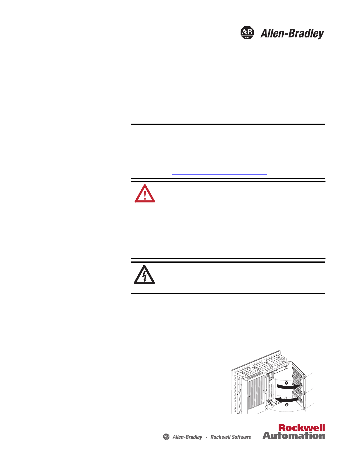
Rear Cover
Follow these steps to remove the rear cover.
1. Disconnect power from the computer.
2. Loosen the three screws that secure the rear cover.
3. Open the cover and detach it from the chassis (1).
Follow these steps to reinstall the rear cover.
1. Fasten the rear cover to the chassis (2).
2. Tighten the three screws to secure the rear cover .
SHOCK HAZARD: The computers contain line voltages. Disconnect all
power to the computer before you install or remove system components.
Failure to do so could result in severe electrical shock or damage to the
computer.
6181X-12TPXPDC Display Computer
Page 2
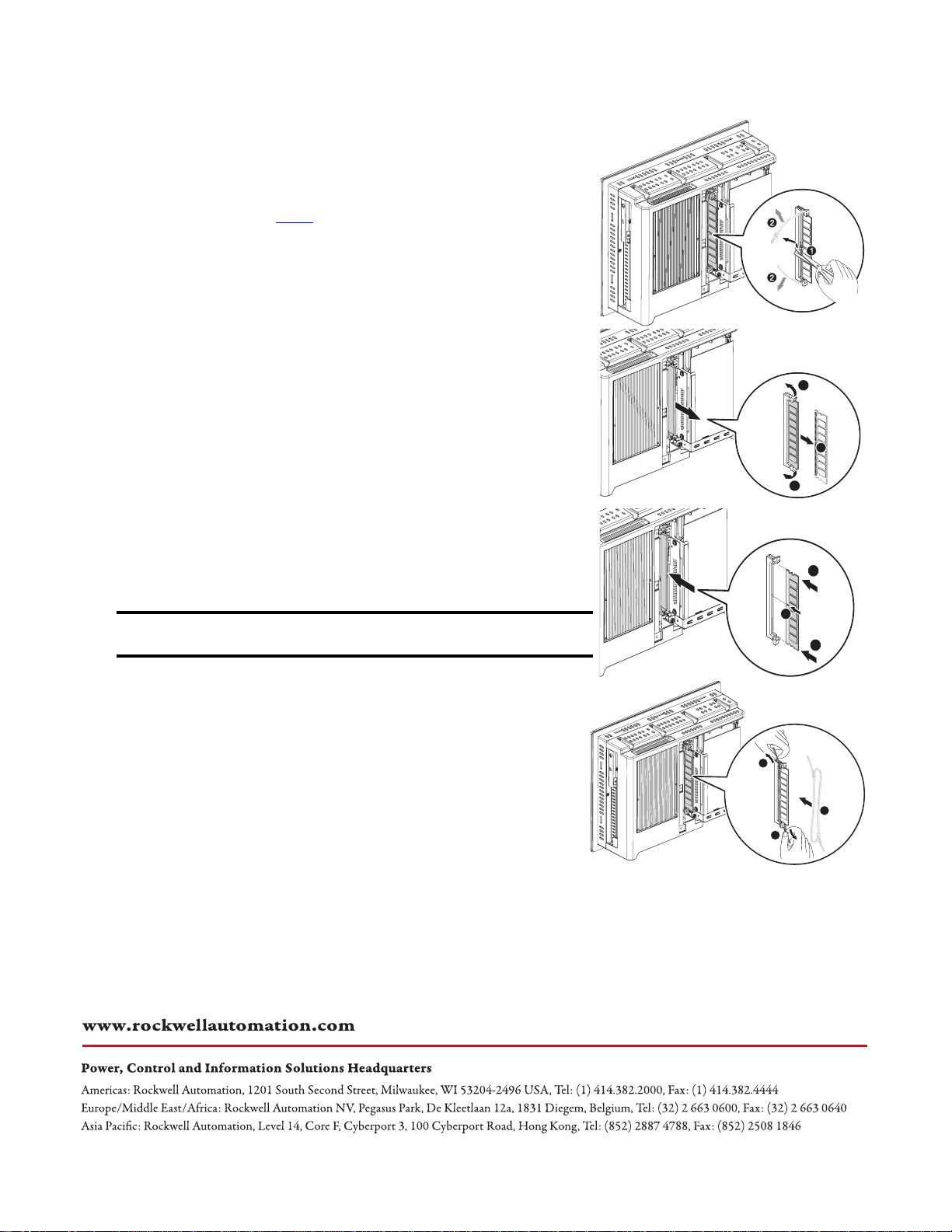
Upgrade the System Memory
Follow these steps to upgrade the system memory.
1. Disconnect power from the computer.
2. Remove the rear cover.
3. If you want to install an additional module instead of replacing the
default one, proceed to step 8
4. Clip the cable tie of the existing memory module (1) and remove it from
the memory slot (2).
5. Completely open the retaining latches securing the memory module (3).
This forces the module up in the slot and makes it easier to remove.
6. Gently remove the memory module from its slot (4).
7. Place the memory module on a static-dissipating work surface or inside
an antistatic bag.
8. Hold the new memory module by its edge and remove it from its
protective packaging.
9. Orient the module so that the notch on its bottom edge aligns with the
keyed surface of the DIMM slot (5).
10. Push the module at both ends to seat it fully into the slot (6).
The holding clips will automatically lock into place once the module has
been seated.
11. Fasten a replacement cable tie around the DIMM slot latches (7).
.
6181X-12TPXPDC
display computer
3
4
3
6
IMPORTANT
Reinstalling the cable tie is required to meet hazardous locations,
mechanical shock, and vibration requirements.
12. Pull the end of the cable tie to lock it in place (8).
13. Cut the excess length of the cable tie.
14. Reinstall the rear cover.
15. Apply power to the computer.
Allen-Bradley, Rockwell Software, and Rockwell Automation are trademarks of Rockwell Automation, Inc.
Trademarks not belonging to Rockwell Automation are property of their respective companies.
Rockwell Otomasyon Ticaret A.Ş., Kar Plaza İş Merkezi E Blok Kat:6 34752 İçerenköy, İstanbul, Tel: +90 (216) 5698400
5
6
8
7
8
Publication 6189V-IN004A-EN-P - September 2010
Copyright © 2010 Rockwell Automation, Inc. All rights reserved. Printed in China..
 Loading...