

Page 1

Installation Instructions
PCI Expansion Slot Kit for VersaView 6181P (1500P) Integrated Display Computer
Catalog Numbers 6189V-2PCI15, 6189V-2PCI15R
Topic Page
About This Publication 1
Important User Information 2
Safety Precautions 3
About the PCI Expansion Slot Kit 3
Install the PCI Expansion Slot Kit 4
Additional Resources 10
About This Publication
This document shows how to install the PCI Expansion Slot Kit in a 6181P 15”
industrial computer.
Publication 6181P-IN003C-EN-P - June 2007
Page 2
2 PCI Expansion Slot Kit for VersaView 6181P (1500P) Integrated Display Computer
Important User Information
Solid state equipment has operational characteristics differing from those of electromechanical equipment.
Safety Guidelines for the Application, Installation and Maintenance of Solid State Controls (publication
SGI-1.1 available from your local Rockwell Automation sales office or online at
http://literature.rockwellautomation.com) describes some important differences between solid state
equipment and hard-wired electromechanical devices. Because of this difference, and also because of the
wide variety of uses for solid state equipment, all persons responsible for applying this equipment must
satisfy themselves that each intended application of this equipment is acceptable.
In no event will Rockwell Automation, Inc. be responsible or liable for indirect or consequential damages
resulting from the use or application of this equipment.
The examples and diagrams in this manual are included solely for illustrative purposes. Because of the many
variables and requirements associated with any particular installation, Rockwell Automation, Inc. cannot
assume responsibility or liability for actual use based on the examples and diagrams.
No patent liability is assumed by Rockwell Automation, Inc. with respect to use of information, circuits,
equipment, or software described in this manual.
Reproduction of the contents of this manual, in whole or in part, without written permission of Rockwell
Automation, Inc., is prohibited.
Throughout this manual, when necessary, we use notes to make you aware of safety considerations.
WARNING
IMPORTANT
ATTENTION
SHOCK HAZARD
BURN HAZARD
Identifies information about practices or circumstances that can cause an explosion in
a hazardous environment, which may lead to personal injury or death, property
damage, or economic loss.
Identifies information that is critical for successful application and understanding of
the product.
Identifies information about practices or circumstances that can lead to personal injury
or death, property damage, or economic loss. Attentions help you to identify a hazard,
avoid a hazard, and recognize the consequences.
Labels may be located on or inside the equipment, for example, a drive or motor, to
alert people that dangerous voltage may be present.
Labels may be located on or inside the equipment, for example, a drive or motor, to
alert people that surfaces may reach dangerous temperatures.
Publication 6181P-IN003C-EN-P - June 2007
Page 3
PCI Expansion Slot Kit for VersaView 6181P (1500P) Integrated Display Computer 3
Safety Precautions
Observe the following precautions when installing the PCI expansion kit.
ATTENTION
ATTENTION
Disconnect all power from computer before removing and installing
components. Failure to disconnect power could result in severe electrical shock
or damage to the computer.
Wear a wrist strap (well grounded) and perform work in a static safe
environment. Electrostatic Discharge (ESD) can damage the VersaView
computer and components.
About the PCI Expansion Slot Kit
The PCI expansion slot kit (catalog numbers 6189V-2PCI15, 6189V-2PCI15R)
provides two PCI card slots for 6181P 15" industrial computers.
Catalog Number 1500P Integrated Display Computer
6189V-2PCI15 Series A…C
6189V-2PCI15R Series D or later
Parts List
The PCI Expansion Kit (6189V-2PCI15, 6189V-2PCI15R) consists of these items:
• Riser bracket (A)
• Riser bracket (B)
• Center support
• PCI riser board
• Slot cover bracket
• Replacement air duct
• 16 M3x6 panhead screws
• 16 M3x6 flathead screws
Publication 6181P-IN003C-EN-P - June 2007
Page 4
4 PCI Expansion Slot Kit for VersaView 6181P (1500P) Integrated Display Computer
Install the PCI Expansion Slot Kit
Follow these steps to install the PCI expansion slot kit.
1. Disconnect power from the computer.
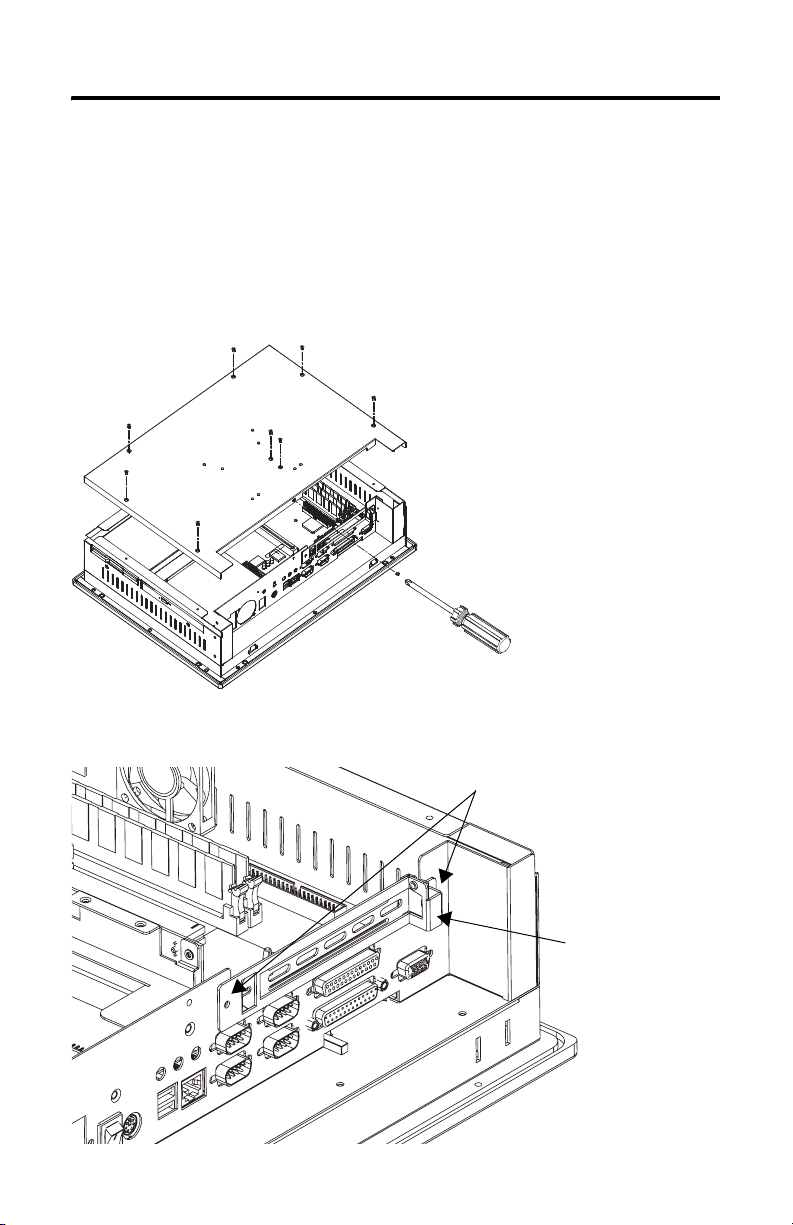
2. Remove the back cover.
Set the nine screws aside for replacing back cover.
3. Remove the slot cover bracket by removing the two screws.
Screws
Publication 6181P-IN003C-EN-P - June 2007
Slot Cover Bracket
Page 5

PCI Expansion Slot Kit for VersaView 6181P (1500P) Integrated Display Computer 5
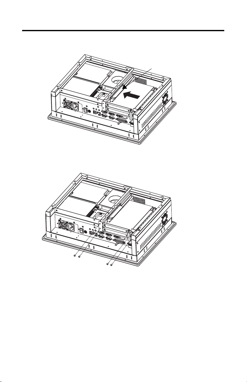
4. Remove the one-slot riser board.
Set the four screws aside for replacing the riser board.
PCI Riser Board
5. Add riser bracket (A) to the chassis by using six M3x6 panhead screws.
Riser Bracket (A)
Publication 6181P-IN003C-EN-P - June 2007
Page 6

6 PCI Expansion Slot Kit for VersaView 6181P (1500P) Integrated Display Computer
IMPORTANT
If using the PCI expansion kit, catalog number 6189V-2PCI15R, for series D or
later computers, reverse steps 6 and 7. First install the center support to the
chassis, then add riser bracket B.
6. For series A…C, add riser bracket (B) to riser bracket (A) using seven, M3x6
flathead screws.
For series D or later, add riser bracket (B) to riser bracket (A) using eight,
M3x6 flathead screws
Riser Bracket (B)
Riser Bracket (A)
7. For series A…C, add the center support to the chassis using two M3x6
flathead screws and one M3x6 panhead screw.
For series D or later, add the center support to the chassis using three M3x6
flathead screws.
Center Support
Publication 6181P-IN003C-EN-P - June 2007
Series A…C Only
(6189V-2PCI15)
Riser Bracket (B)
Riser Bracket (A)
Page 7

PCI Expansion Slot Kit for VersaView 6181P (1500P) Integrated Display Computer 7
8. Add the riser board using the two screws from step 4.
PCI Riser Board
Center Support
Riser Bracket (B)
Riser Bracket (A)
9. You can attach the slot cover bracket to the chassis with or without PCI
cards.
• To install PCI cards at this time, follow steps 9a - c.
• To attach the slot cover bracket to the chassis without PCI cards go to
step 9c.
a. Attach PCI cards to the slot cover bracket.
Slot Cover Bracket
Publication 6181P-IN003C-EN-P - June 2007
PCI Cards
Page 8
8 PCI Expansion Slot Kit for VersaView 6181P (1500P) Integrated Display Computer
b. Connect PCI cards to the riser board.
PCI Riser Board
c. Fasten the slot cover bracket to the chassis using four M3x6 panhead
screws.
10. If you are installing the expansion kit on a series A computer, you may
discard the replacement air duct and proceed to step 11.
If you are installing the expansion kit on a series B or later computer, you
must replace the air duct that provides cooling air to the processor.
a. Remove the existing air duct from the back cover of the chassis by
removing the three screws.
b. Attach the replacement air duct to the back cover of the chassis using the
same three screws.
c. Set the opening of the duct to its full-open position, if possible.
Publication 6181P-IN003C-EN-P - June 2007
Page 9

PCI Expansion Slot Kit for VersaView 6181P (1500P) Integrated Display Computer 9
If the installed PCI cards interfere with the fully-opened duct, reduce the
opened position to eliminate the interference.
11. Reinstall the back cover over the chassis and replace the nine screws from
step 2.
Publication 6181P-IN003C-EN-P - June 2007
Page 10

10 PCI Expansion Slot Kit for VersaView 6181P (1500P) Integrated Display Computer
Additional Resources
For additional information on the VersaView computers, refer to VersaView
Integrated Display Computers User Manual, publication 6181P-UM001
You can view or download publications at
http://literature.rockwellautomation.com
documentation, contact your local Rockwell Automation distributor or sales
representative.
. To order paper copies of technical
.
Publication 6181P-IN003C-EN-P - June 2007
Page 11

Notes:
PCI Expansion Slot Kit for VersaView 6181P (1500P) Integrated Display Computer 11
Publication 6181P-IN003C-EN-P - June 2007
Page 12

Rockwell Automation Support
Rockwell Automation provides technical information on the Web to assist you in
using its products. At http://support.rockwellautomation.com
technical manuals, a knowledge base of FAQs, technical and application notes,
sample code and links to software service packs, and a MySupport feature that you
can customize to make the best use of these tools.
For an additional level of technical phone support for installation, configuration,
and troubleshooting, we offer TechConnect Support programs. For more
information, contact your local distributor or Rockwell Automation representative,
or visit http://support.rockwellautomation.com
.
Installation Assistance
If you experience a problem with a hardware module within the first 24 hours of
installation, please review the information that's contained in this manual. You can
also contact a special Customer Support number for initial help in getting your
module up and running.
, you can find
United States 1.440.646.3223
Outside United
States
Monday – Friday, 8am – 5pm EST
Please contact your local Rockwell Automation representative for any
technical support issues.
New Product Satisfaction Return
Rockwell tests all of its products to ensure that they are fully operational when
shipped from the manufacturing facility. However, if your product is not
functioning, it may need to be returned.
United States Contact your distributor. You must provide a Customer Support case number
Outside United
States
Allen-Bradley, VersaView, TechConnect, and Rockwell Automation are trademarks of Rockwell Automation, Inc.
Trademarks not belonging to Rockwell Automation are property of their respective companies.
Publication 6181P-IN003C-EN-P - June 2007 PN 41061-341-01(3)
Supersedes Pub lication 6181P-IN003B-E N-P - February 2004 Copyright © 20 07 Rockwell Automati on, Inc. All rights reser ved. Printed in the U.S.A.
(see phone number above to obtain one) to your distributor in order to
complete the return process.
Please contact your local Rockwell Automation representative for return
procedure.
 Loading...