

Page 1
Industrial 19" CRT Monitor
(Bullet in 61 57 -C )
Installation and User Manual
Page 2
2
Table of Contents
7
7D
DEOH R
EOH RI
Industrial 19" CRT Monitor
Description........................................................................... 3
Package Contents................................................................. 6
Installation Guidelines.......................................................... 6
Panel Mounting (6157-CE/ 6157-CF)................................... 8
Rack Mounting (6157-CB)................................................... 14
Connecting the 6157- C Industrial Monitor........................... 21
Operating the 6157- C Industrial Monitor............................. 25
Routine Maintenance............................................................ 39
Troubleshooting................................................................... 40
Allen-Bradley Support ......................................................... 42
Appendix A: Touchscreen Serial Interface
Description........................................................................... 43
Setting Up the Touchscreen Interface.................................... 43
Performing a Calibration...................................................... 45
Appendi x B : Video Cabl es
HD-15 Connectors ............................................................... 46
BNC Connectors.................................................................. 47
Specifications
I &RQWH
&RQWHQ
...................................................................... 48
QWV
WV
.............................................. 3
........................ 43
................................................. 46
Importan t User Informat ion
Solid state equipment has operational characteristics differing from those of
electromechanical equipment. "Safety Guidelines for the Application, Installation, and
Maintenance of Solid State Controls" (Publication SGI-1.1) describes some important
differences between solid state equipment and hard-wired electromechanical devices.
Because of this difference, and because of the wide variety of uses for solid state
equipment, all persons responsible for applying this equipment must satisfy themselves
that each intended application of this equipment is acceptable.
In no event will Rockwell Automation be responsible or liable for indirect or
consequential damages resulting from the use or application of this equipment.
The examples and diagrams in this manual are included solely for illustrative purposes.
Because of the many variables and requirements associated with any particular
installation, Rockwell Automation cannot assume responsibility or liability for actual
use based on the examples and diagrams.
No patent liability is assumed by Rockwell Automation with respect to use of the
information, circuits , equi pment, or sof tware des c ribe d i n this m anual .
Reproduction of the contents of this manual, in whole or in part, without written
permis si on of Rockwell Automation is prohibited.
Throughout this manual, we use notes to make you aware of safety considerations.
ATTENTION:
circumstances that can lead to personal injury or death,
property damage, or economic loss.
Important:
application and understanding of the product.
Identifies infor mation t hat is es peci al ly impor tant f or successfu l
Identifies information about practices or
Publication 6157-UM001A-EN-P
Page 3
Industrial 19" CRT Monitor
Descript ion
,QGXVWULDO
,QGXVWULDO
The 6157-C Industrial 19" CRT Monitor is a general-purpose monitor
suitable for a wide range of industrial computing applications. It offers
the following features:
Panel a nd ra c k mount enclosu res
•
Pure flat screen
•
Reliable and rugged industrial design
•
Bright, c risp display
•
Touchscreens
•
Sync- o n-green, separa te sync , and comp osite sync video su pport
•
On-scr een disp la y f or easy setup
•
Versatile multi-sync design (640x480 to 1600x1200 resolution)
•
&57 0RQLW
&57 0RQLWR
RU
U
3
Note:
This monitor can display resolutions up to 1600x1200
at 75 Hz. If you experience unexpected results
operating the monitor at this resolution, verify that the
monitor is operating a t 75 Hz or less.
ATTENTION:
document generates, uses, and emits radio frequency
energy. The equipment has b een tested and fou n d to
comply with FCC Rules, Part 15, subpart J, for Class A
computing devices.
The use of non-shielded interface or power cords with
All e n-Br adley indu str i al mo nitor s is p rohib ited.
ATTENTION:
typically about 0.05 mR/hr maximum, well below the
0.5 mR/hr maximum recommended by the US.
Depa rtment of Heal th a nd Human Resources and
specified in "Federal Performance Standards for
Television Receivers", Section 10, Part 1020, Title 21, of
the U. S. Code of Regulation (PL90-620), Vol. 38, No.
198.
These monitors ar e equippe d with X-r ay pro tecti on
circuits that cause automatic shutdown of the equipment
in ca se its X -ray emissions be gin t o app roach federal
limits.
The equipment described in this
X-ray emissions from these monitors are
Publication 6157-UM001A-EN-P
Page 4
4
Industrial 19" CRT Monitor
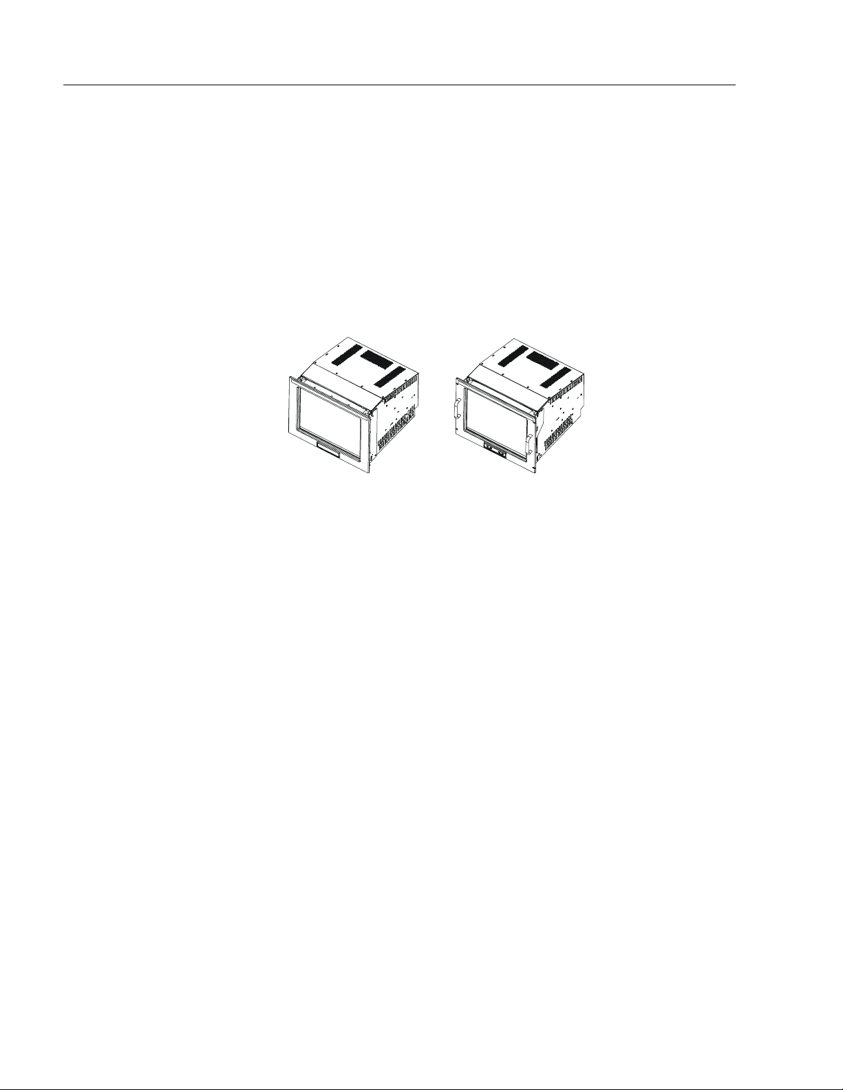
Models
The 6157- C Industrial Monitor is available in the following models:
Panel mount with front controls (6157-CE)
•
Panel mount with rear controls (6157-CF)
•
Rack mount (6157-CB)
•
Figure 1
6157-C Monitor Models
Panel Mount Rack Mount
(6157-CE/6157-CF) (6157-CB)
Availabl e O pt io n s
The following options are available on each model of the 6157- C
Industrial Monitor:
Video interface options
•
(HD-15 and five BNCs through an adapter cable)
Resistiv e or ca p acitive touchscreen
•
Surface acoustic wave (SAW) touchscreen option (6157-CB only)
•
Touchscreen cable opti ons
•
Video cable opti ons
•
Power cord options
•
Publication 6157-UM001A-EN-P
Page 5
Industrial 19" CRT Monitor
Part Numbers
The part number for your particular unit consists of the model number
(6157) followed by a nine-digit code indicating the options on your unit.
Example:
5
6157 -
CE D A A Z A A Z Z
1 2345678910
Following are exp lana tio ns of t he pa rt nu mbers for t he various mode ls of
the 6157-C units.
Table A
Catalog Number Explanation for 6157- C Industrial Monitors
Position Option Option
Letter
2
3 Touchscreen/
4 Vid eo In terfac e A HD- 15
5
6
7 External Video
8 Touchscreen
9 Future Options Z None
10 Enclosure
Display/
Enclosure
Display Shield
Power Inp ut/
Line Cord
Future Options Z None
Cable
Cable
Accessories
CB Rack Mount, NEMA 1, 9U, Front Controls
CE Panel Mount, NEMA 4/4X, 9U, Front Controls
CF Panel Mount, NEMA 4/4X, 9U, Rear Controls
B Resisti ve A nt ig lare Touc hs c reen
D Capacitive Antiglare Touchscreen
G SAW Polished Touchscreen (Rack Mount Only)
W Tempered Glass Anti -refle c tive Display Shield
Z None (No Display Shield)
A 120/240 VAC, USA Power Cord
B 120/240 VAC, No Power Cord
A 6 ft (1.8 m) HD-15 - HD-15 Cable
B 15 ft (4.6 m) HD-15 - HD- 15 Cable
K 1ft (0.3 m) 5-BNC - HD-15 Cable
A 6 ft (1.8 m) DE9 - DE9 Cable
B 15 ft (4.6 m) DE9 - DE9 Cable
ZNone
B 18" Rack Mount Slides (Pair)
C 24" Rack Mount Slides (Pair)
D 18" Rack Mount Slides (Pair), EIA 19" 1U Adapter
E 24" Rack Mount Slides (Pair), EIA 19" 1U Adapter
ZNone
Category Description
Panel
Panel
Note:
Not a ll op ti o ns are a vailab le with all models.
Publication 6157-UM001A-EN-P
Page 6

6
Package Contents
Installation Guidelines
Industrial 19" CRT Monitor
Before unpacking a new monitor, inspect the shipping carton for damage.
If damage is visibl e, immediat e ly conta c t the shipper a nd request
assistance. Otherwise, proc eed wit h u npa ck i n g.
Note:
The monitor shipping carton contains the following items:
Monitor
•
Pa cka g e of mou nt i ng ha r dwa r e
•
AC power cord (optional)
•
Video cable (optional)
•
Enclosure accessories (i.e. rack sides for rack mount only) (optional)
•
This user manual
•
An 6157- C Industrial Monitor with a touchscreen option is shipped with
these additional items:
Supporting software and manuals
•
RS-232 serial extension cable (optional)
•
When installing the unit, it is important to consider environmental
factors at the site that could affect performance as well as possible
effects from equipment operation on personnel and nearby equipment.
Make s ure you ke ep the orig inal packagi ng for the mo nitor
in case you need to return the monitor for repair.
Note:
Important:
Remember th at hea t ris es—many time s t he temper at ure at
the top of an enclosure is much higher than the rest of the
enclosure if the air is not circulating. Without active
cooling or an internal fan, the temperature at the top of an
enclosure can be 10° - 20°C hotter than at the middle or
bottom of the enclosu re.
This monito r is designed to operate a t a range of extr emes,
however it is not good design practice to continuously
op erate the monitor at th e highest end of the sp ecified
tem perature ra n ge.
While the product will operate at its highest specified
tempera ture, the ov erall life s p an of a ny elec tronic d e v i ce is
shorten e d whe n it operates at its highest rated te mperature.
Publication 6157-UM001A-EN-P
Page 7

Industrial 19" CRT Monitor
Following the guidelines below will help ensure that the monitor will
provide safe and relia ble serv ic e.
Ensure that sufficient
•
is available from a single phase AC
power
outlet at the site.
Ensure that sufficient
•
is available around air inlets and outlets
space
to provide the circulation necessary for cooling. Never allow air
passages to become obstructed. The monitor is equipped with a fan
to ensure proper cooling.
7
• Dust and smoke
part icl es ca n ca u s e pr obl ems, since they can collect
at ventilating holes in the enclosure and interfere with cooling.
Accordingly, where dust and smoke are problems it is especially
important to keep air vents clean. Refer to the Routine Maintenance
section (Page 39) for more information.
Ensure that the
•
ambient air temperature
will not exceed the
specified maximum temperature. A user supplied fan, heat exchanger,
or air conditioner may be required to meet this condition in some
installations.
Leav e the monitor’s
•
enclosure or cover
in place at all times during
oper ation. The cover aff ords p rotecti on against hi gh volt ages inside
the monitor and inhibits radio-frequency emissions that might
interfere with other equipment.
The Federal Communications Commission has prepared a pamphlet
•
that addresses the pr oblem of
radio frequency interference
to radio
and telev i si on recept ion, which shoul d be consu lted in ca se of
problems with such interference. This publication, “How to Identify
and Resolve Radio/TV Interference Problems” (Stock #004-00000345-4) may be obtained from the US. Government Printing Office,
Washington, DC 20402.
Determin e t he min imum a n d maxi mum a mbient
•
humidity
for the
monitor by consulting the specification sheets at the back of this
manual. Ensure that the humidity of the ambient air will not exceed
these limits. In very dry environments, static charges build up very
rea dily. Pr oper grou nding of the equipment through the AC po w er
cord can help reduce the likelihood of static discharges, which may
cau se shocks and damag e e lect ronic compo n ents.
Publication 6157-UM001A-EN-P
Page 8
8
Panel Mounting (6157-CE/
6157-CF)
Industrial 19" CRT Monitor
When properly installed, the panel mount version of the 6157- C
Industrial Monitor is designe d to p rovide prot ecti on aga inst water a nd
dust to NEMA 4 and 4X (IP 65 equivalent) and NEMA 12 (IP 52
equivalent) standards.
No slides or shelves are required because the 6157- C Industrial Monitor
is designed to be supported by the panels in which it is installed.
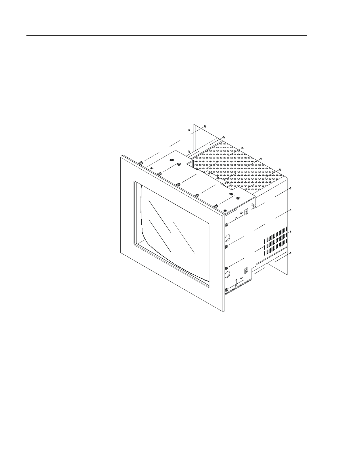
Figure 2
Generic Panel Mount Diagram
Publication 6157-UM001A-EN-P
Tools Needed
In addition to the tools required to make the cutout, you will need the
following tools to mount the monitor:
3/8 in. deep well socket
•
¼ in. drive extension – 12 in. or longer
•
¼ in. drive ratchet or ¼ in. drive torque ratchet
•
Page 9
Industrial 19" CRT Monitor
Panel Mounting Guidelines
Observe the following precautions before installing the unit in a panel:
Confirm that there i s adequa te space be hin d the pa nel. Remember to
•
allow extra space for air circulation and cabling. Allow 63.5 mm
(2.5 in) behind and 50.8 mm (2 in) above, below, and on each side for
air cir c u l atio n and cabling.
Confirm that the cabinet is deep enough to accommodate the
•
monitor's depth while providing rear clearance for airflow. A cabinet
with depth of 523.7 mm (20.62 in.) is sufficient.
Take precaut ions so that metal cuttings d o n ot enter a ny comp onents
•
that are already installed in the panel.
Supporting panels should be at least 14 gauge to ensure proper
•
sealing against water and dust and to provide proper support. The
mounting hardware supplied accommodates panels up to 6.4 mm
(0.25 in) thick.
9
Note:
Supporting panels must be cut and drilled to
specifications prior to installation.
ATTENTION:
Failure to follow these warnings may
result in personal injury or damage to the panel
components.
Publication 6157-UM001A-EN-P
Page 10
10
Industrial 19" CRT Monitor
Mounting the 6157-CE/6157-CF in a Rack
Due to the front panel size and stud pattern, the panel mount versions of
the 6157- C Industrial Monitor can be installed in an EIA 19 in. 9U panel
standard rack. Refer to the following figure:
Figure 3
Generic Rack Mounting Diagram
Publication 6157-UM001A-EN-P
Important:
If you install the panel mount versions of the 6157- C
Industrial Monitor in a rack, you must ensure that the rack
can support the weight of the monitor. You may need to
install a support or shelf under the rear of the monitor to
support the weight.
Page 11
Industrial 19" CRT Monitor
Panel Mount Dimensions (6157-CE/6157-CF)
This section provides diagrams you need to follow to install the unit.
Dimensions are supplied in mm [in.]
Figure 4
6157-CE/6157-CF Industrial Monitor Dimensions
11
Publication 6157-UM001A-EN-P
Page 12
12
Industrial 19" CRT Monitor
Panel Mounting Procedure
1. Confirm that the shipping carton contains a package of 10-32 lock
nuts and fl at wash ers. You will n e e d 18 nuts and washers f or
installati on. E xtra lock nu ts and washers are pr ovided.
2. Refer to t he ph ysical di me nsion drawi ng ( Figu re 4) and conf irm that
th ere is adequat e space be hin d th e pa nel. R emem ber to allow extra
space for cir c ulatio n and cabling.
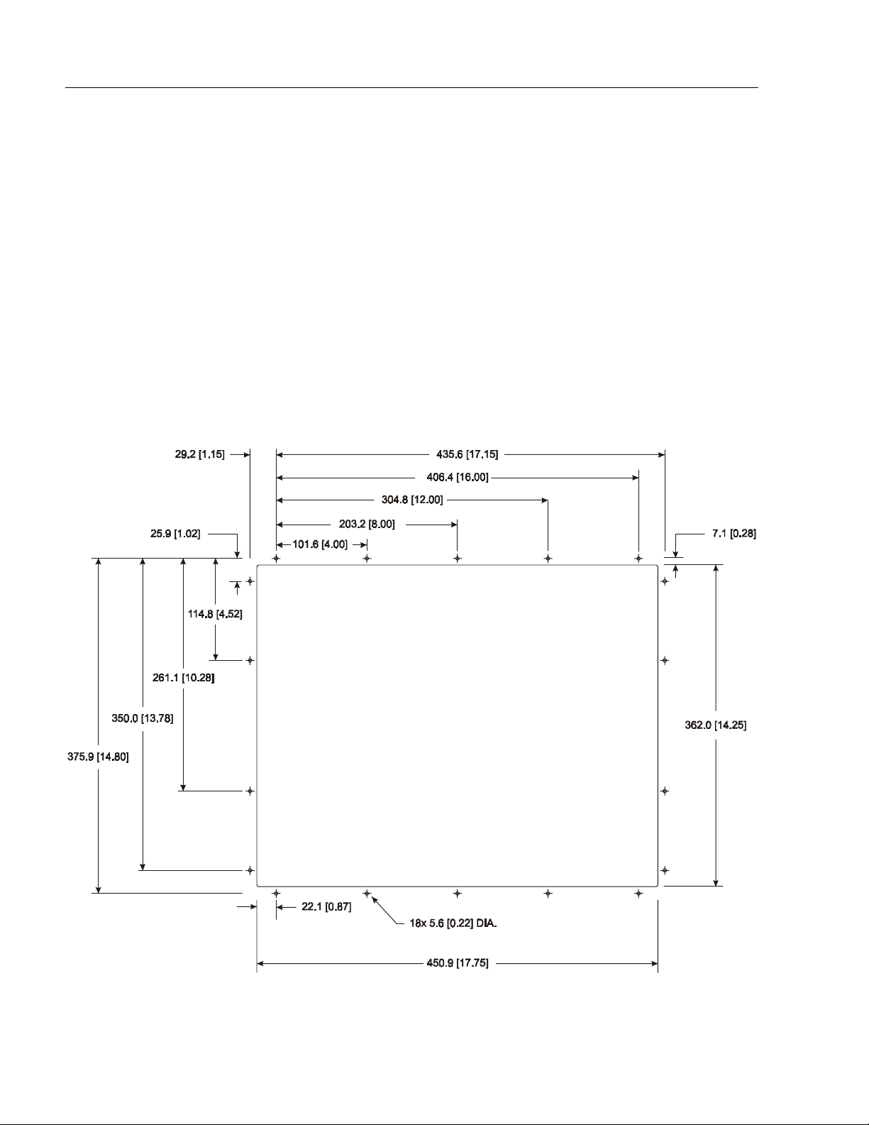
3. Refer to the panel cutout drawing below for dimensions of the panel
cutout and mounting hole locations. Cut and drill the panel.
Note:
Figure 5
Panel Mounting Cutout
Use #10-32 or M5 self-locking nuts for mounting.
Publication 6157-UM001A-EN-P
Page 13
Industrial 19" CRT Monitor
4. Carefully remove the monitor from its packaging. Avoid damaging
the monitor gasket.
It will be easier to install the monitor if you support it with a shelf
Tip:
or other support adjusted to the appropriate height.
5. Insert the monitor in the panel cutout from the front. Do not damage
the threaded mounting studs as you position the monitor.
6. Secure the unit with the lock nuts and washers provided. Tighten
evenly to 24 inch-pounds of torque.
13
Important:
To ensure a proper seal, be sure to install a washer and
nut on each of the 18 mounting studs.
ATTENTION:
Mounting nuts must be tightened to a
torque of 24 inch-pounds to provide panel seal and
avoid potential damage. R ockw e ll Automa ti on
assumes no responsibility for water or chemical
damage to the monitor or other equipment within the
enclosure due to improper installation.
7. Remove the protective adhesive sheet from the screen of the
Industrial Monitor. The sheet is designed to prevent scratching of
the polycarbonate screen protector or the optional touchscreen
during shipping and installation. It should be removed before use.
Publication 6157-UM001A-EN-P
Page 14

14
Rack Mounting (6157-CB)
Industrial 19" CRT Monitor
When properly installed, the 6157-CB industrial monitor is designed to
provid e p rotection to NEMA 1 (IP 10 equ ivalent) standards.
The rack mounting versions of the 6157- C Industrial Monitor are
designe d for insta llation in a rack enc losure that co nfor ms to EIA
standards for equipment with 19" (483 mm) wide rails.
Note:
Retainer screws prevent the unit from being pulled out on
its slides accidentally; they are not intended to support the
weight of the unit.
Tools Needed
You will need the following tools and hardware:
EIA panel mounting hardware
•
Chassis slides or shelf
•
Screwdriver
•
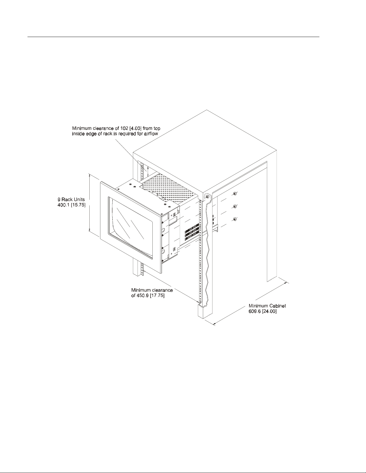
Rack Mounting Guidelines
Observe the following precautions when installing this unit in a rack:
The cabinet must be tall enough to accommodate the monitor's panel
•
height of 9 rack units, 15.75 in. (400 mm), and deep enough to
accommodate the monitor's depth while providing rear clearance for
cabling and air flow. A cabinet with depth of 24 in. (610 mm) is
sufficient. A minimum clearance of 4 in. (102 mm) from the top
inside edge of the rack is required for airflow.
Publication 6157-UM001A-EN-P
The monitor is designed to be supported in the cabinet by telescoping
•
slides. Slide mounting points are provided on the lower sides of the
monitor chassis. These mounting points are designed to accommodate
General Devices Co. Chassis-Trak
slides. Slides of this kind are available from Rockwell Automation in
18 in. and 24 in. lengths, with or without 6 in. extenders.
®
Model C-300-S or equivalent
Page 15
Industrial 19" CRT Monitor
15
Note:
The mounting rails that run vertically along the inside
edges of the fr ont a nd rear openings of EIA rac k
cabinets can be of two types:
“Wide” rails have holes spaced 0.5 in. (12.7mm)
•
and 1.25 in. (31.8mm) on centers, in a repeating
patter n . Th ese rails are prevalent in E urope.
“Universal” rails have holes spaced 0.5 in.
•
(12.7mm), 0.625 in. (15.9mm), and 0.625 in.
(15.9mm) on centers, in a repeating pattern. Thus,
the “universal” rails have a hole pattern that
contains the “wide” pattern but provides an
additional hole at the midpoint of the pattern.
“Universal” rails are most prevalent in the US.
ATTENTION:
Failure to follow these warnings may
result in personal injury or damage to the panel
components.
Publication 6157-UM001A-EN-P
Page 16
16
Industrial 19" CRT Monitor
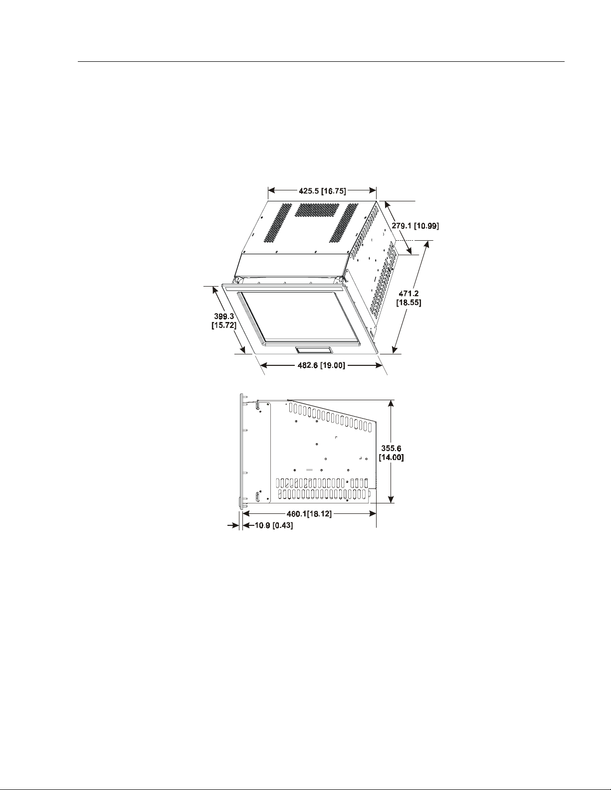
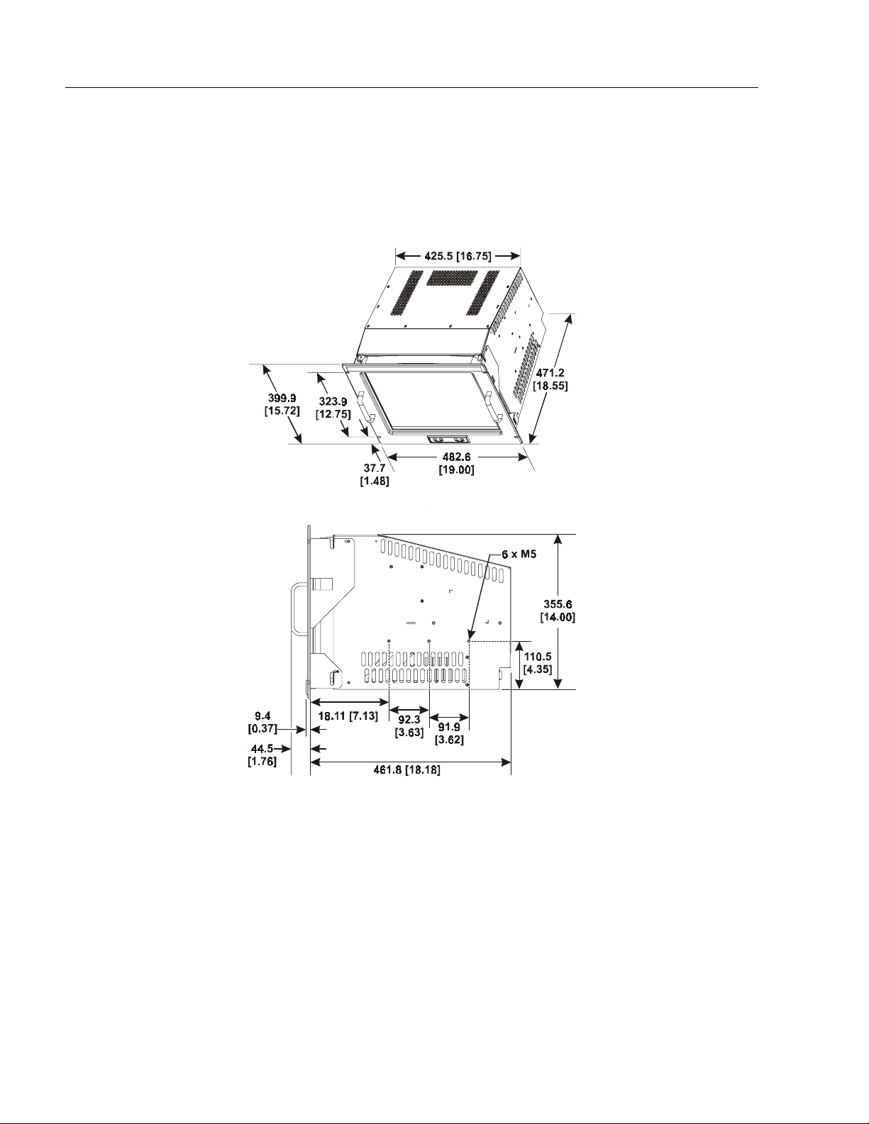
Rack Mounting Dimensions (6157-CB)
This section provides diagrams you need to follow to install the unit.
Figure 6
6157-CB Industrial Monitor Dimensions
Publication 6157-UM001A-EN-P
Page 17
Industrial 19" CRT Monitor
17
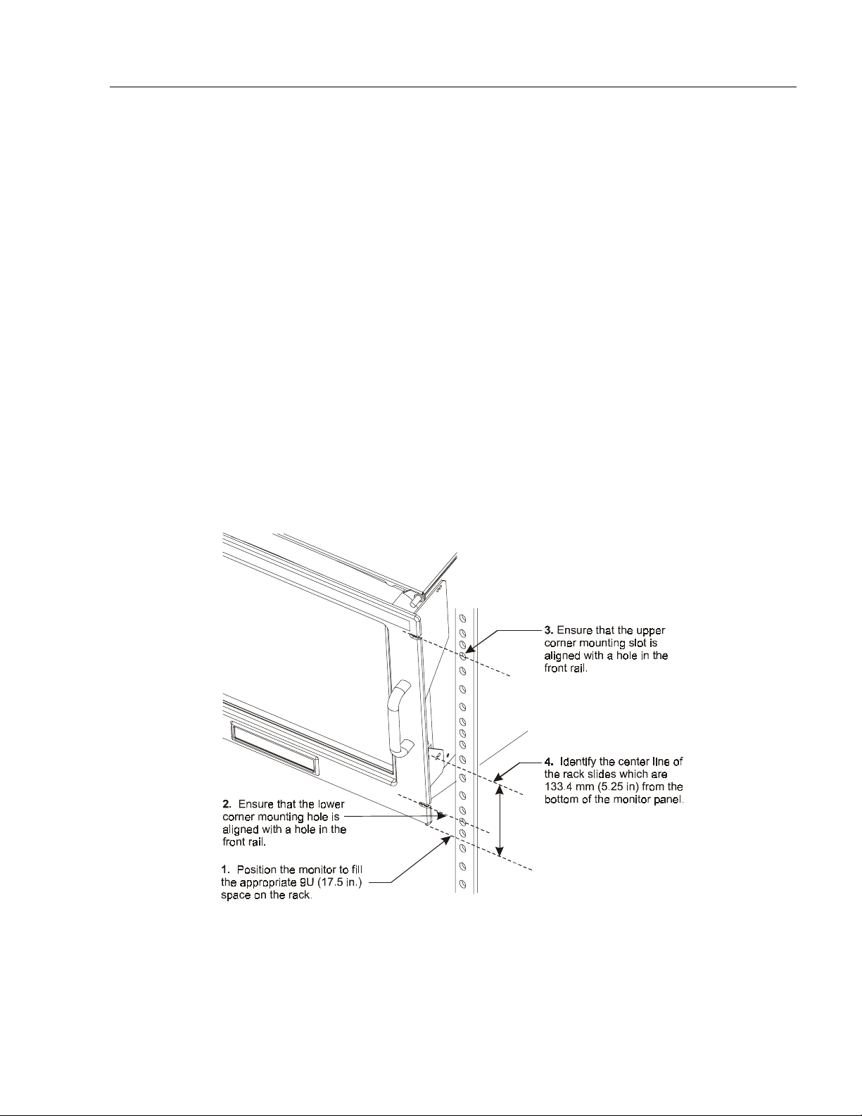
Rack Mounting Procedure
Step 1 - Locate the mounting areas:
You must allocate the required space in your enclosure for the monitor.
The monitor’s panel height is 9 rack units (15.75 in. or 400 mm) and you
must determine if panel spacers are required above or below the monitor.
Locate the following areas to mount the slides:
Locate the points at which the bottom edge of the monitor front panel
•
will intersect the cabinet front mounting rails. The four slots in the
monitor front panel should be aligned with holes in the front
mounting rails.
Locate points on the front rails 5.25 in. (133 mm) above the points of
•
where the bot tom edge of th e monitor pane l intersect s t he r ail . Th ese
points indicate the center line of each slide.
Locate points on the rear rails equal in height to the slide center line
•
points on the front rails.
Figure 7
Mounting Areas on a Rack
Publication 6157-UM001A-EN-P
Page 18
18
Industrial 19" CRT Monitor
Note:
Clearance between the insi de e dges of the fron t
mounting rails is nominally 17.75 in. (451 mm) for
standard cabinets.
This c learance can vary s omewha t and might or might
not be adjustable. Ensure that the clearance is at least
17.65 in. (448 mm) for standard monitors and at least
17.73 in. (450 mm) for monitors with magnetic shields
option installed.
Note:
Magnetic shields are secured with nylon rivets inserted
through their sides. The rivet heads require clearance
greater than 17.73 in. (450 mm). If this additional
clearance is not available, the rivets must be removed
before the monitor is installed in the cabinet.
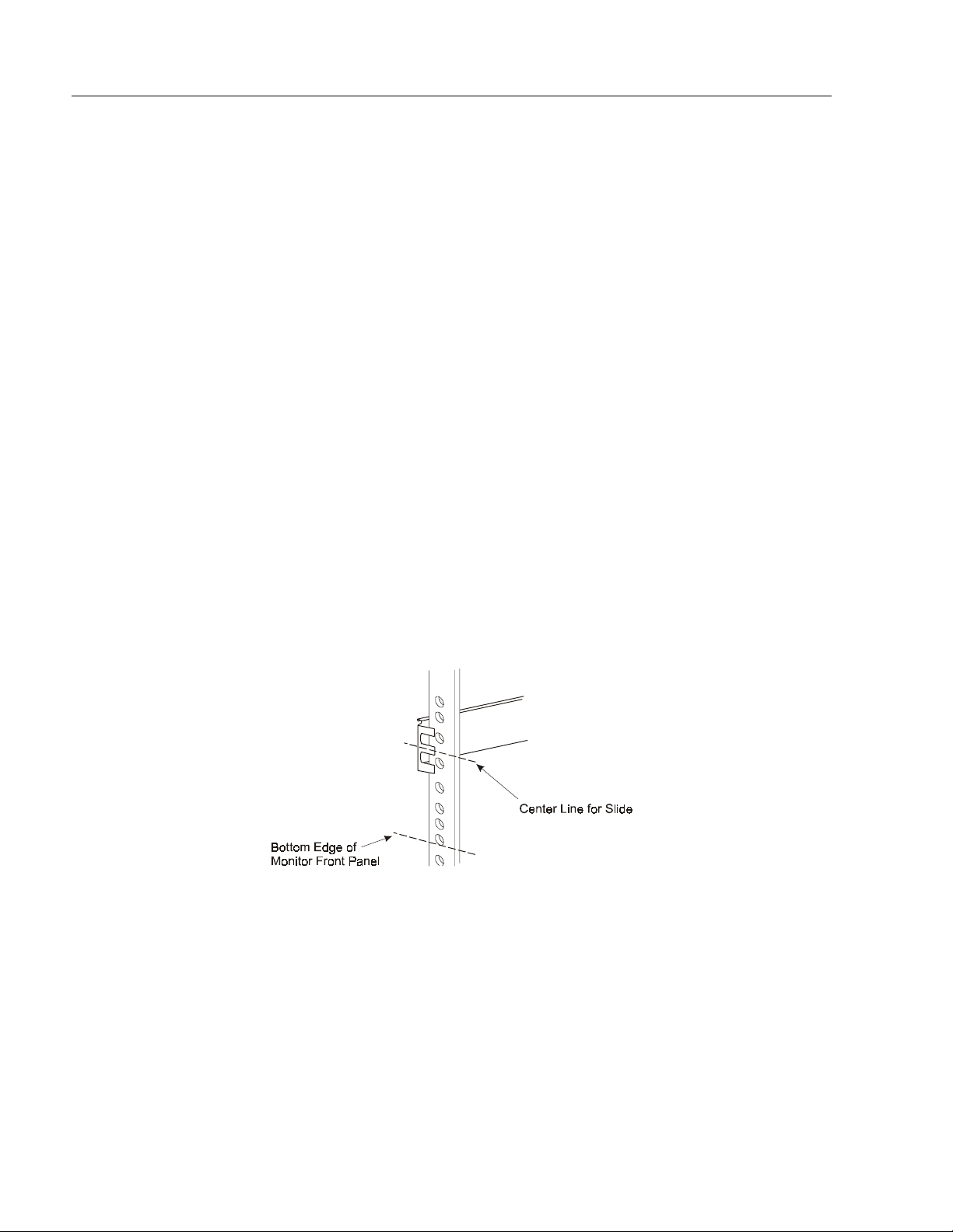
Step 2 - Install the slides in the cabinet:
1. Disassemble each slide by pressing out the spring-loaded stop that
holds the intermediate section of the slide to the stationary section.
Pull the intermediate section all the way out of the stationary section.
2. Mount the stationary section of one slide to the front and rear
mounting rails using the hardware supplied with the slides. Ensure
that the slide is aligned on the center line you located previously.
Figure 8
Chassis Slide Aligned on Center Line
3. Tighten the mounting screws enough to hold the slides in place.
Publication 6157-UM001A-EN-P
Page 19

Industrial 19" CRT Monitor
4. Repeat these steps to mount the stationary section of the other slide
to the front and rear mounting rails on the opposite side.
5. Measur e the space betw een the inside ed ges o f the sta tiona ry slides
to determine the clearance. Adjust the spacing to 16.8 in. (427 mm
6. Fully tighten the mounting screws holding the stationary sections to
the front and rear mounting rails of the cabinet.
7. Locate the holes in the front mounting rails corresponding to the
monitor’s front panel mounting holes. Install clip nuts behind the
ho les in the ra ils i f the holes are not threaded.
Step 3 - Mount the slides on the monitor:
1. Take up the sections of the slides previously removed from the
stationary s e c tio ns. Pull the int erior sectio ns out of the intermediat e
sections far enough to gain access to the mounting holes in the
interior sections.
2. Align the interior section’s mounting holes with corresponding holes
on the brace of the monitor chassis. Attach the interior section of the
slide to the side of the chassis with hardware supplied. Tighten
screws securely.
19
3. Repeat these steps to attach the interior section of the other slide to
the opposite side of the chassis.
Step 4 - Install the monitor in the cabinet:
1. Position the monitor chassis, with slide extensions installed, in front
of t he prepared cab inet.
2. Lift the monitor chassis to the height required to align the
intermediate sections of the slides (attached to the chassis) with the
corresponding stationary sections (attached to the cabinet rails).
ATTENTION:
To avoid danger of personal injury or
accidenta l damage to equipmen t , it is recommended
the monitor be lifted by two persons, both wearing
back braces.
3. Push the intermediate sections of the slides into the stationary
sections until the retaining locks are engaged.
4. If the monitor will be accessible from the rear after installation,
cabling may be installed from the rear at a later time. Otherwise,
power and vide o c abling should be installed at this time, while the
monitor is supported by the slides in extended position.
Publication 6157-UM001A-EN-P
Page 20

20
Industrial 19" CRT Monitor
5. Slide the chassis into the cabinet. Secure the monitor chassis to the
cabinet by installing screws through the four holes in the monitor
front panel in such a way that they engage the threaded holes on the
clip nuts installed previously behind corresponding holes in the rails.
Note:
Retainer screws prevent the unit from being pulled out
on its slides accidentally; they are not intended to
support the weight of the unit.
6. Remove the protective adhesive sheet from the screen of the
Industrial Monitor. The sheet is designed to prevent scratching of
the polycarbonate screen protector or the optional touchscreen
during shipping and installation. It should be removed before use.
Publication 6157-UM001A-EN-P
Page 21
Industrial 19" CRT Monitor
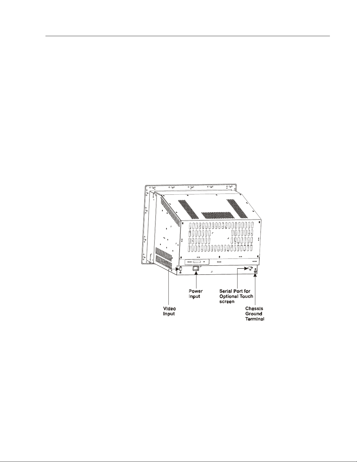
Connecting the 6157- C Industrial Monitor
The rear panel of the 6157- C Industrial Monitor has connectors for
attaching cables to accomplish the following:
Connecting to a host video source
•
(HD-15 VGA or optional HD-15 to BNC adapter)
Connecting to a host t ouc hscreen control port (DE-9 connector)
•
(optional)
Connecting to AC power
•
21
Note:
Some connectors on your monitor may differ from the
following figure.
The following figure illustrates the standard configuration for the 6157C Indu strial Monitor.
Figure 9
Rear Panel
Publication 6157-UM001A-EN-P
Page 22

22
Industrial 19" CRT Monitor
Connecting the Video Source
The video connection to the host is made through a HD-15 (female)
connector or to BNC connectors using a 5-BNC to HD-15 adapter cable.
For more information on using an HD-15 video cable to connect to the
host computer, refer to Appendix B (Page 46).
To establish a signal using the HD-15 connector:
1. Obtain a shielded, properly terminated video cable of length as short
as possible. Longer cables (up to approximately 50 feet in some
cas es) ma y be used, provide d they ar e p roperl y c onst ruc ted. Your
package may include a 6- or 15-foot video cable, if specified.
2. Connect one end of the cable to the female HD-15 video input
connector on the rear panel of the monitor.
3. Conn e ct t h e other end to t he outp ut of any I BM-c ompa tibl e VGA
ada pter or other video generator.
Note:
It may be possible to connect the monitor to video
generator s that do n ot conform to VGA standar ds. The
main requirement is that the generator provide analog
RGB video signals (0.714V or 1V above reference
black into 75 ohms) and separate horizontal and vertical
sync signals. Please contact your Rockwell Automation
representative for more information,
To establish a signal using the BNC to HD-15 BNC adapter cable:
1. Obtain 75-ohm coaxial cables fitted with BNC connectors. Make
su re the c ab les are of equal lengt h .
Note:
A BNC to HD-15 adapter cable is available from
Rockwell Automation for connecting the monitor to a
BNC terminated RGB video source.
2. Connect one end of the cable to the appropriate BNC input
connectors (R, G, B, HS/CS, VS) on the video source.
Note:
The BNC ca bles ar e color coordinated for the red,
green, and blue connectors. The horizontal and vertical
sync connectors are typically gray and black. The
letters H (horizontal sy nc) a nd V ( verti c al s ync) a re
embossed on the plastic covering of the appropriate
connectors.
Publication 6157-UM001A-EN-P
3. Connect the other end to the corresponding connector of the BNC to
HD-15 adapter cable.
Page 23

Industrial 19" CRT Monitor
4. Connect the adapter to the HD-15 video connector on the rear panel
of the monitor.
Connecting the Touchscreen Interface
The serial touc hscreen int erface connection to the host is made throug h
an RS-232 DE-9 (female) connector located on the rear panel.
The optional touchscreen provides a high-resolution touch input system.
Driver software included with the package allows the touchscreen to
function with many popular DOS and Windows
applications as a pointing device (mouse).
®
-based industrial
23
Note:
Refer to the manual included with the touchscreen option
and Appendix A of this manual (page 43) for additional
details on the installation and operation of the touchscreen.
To connect the touchscreen:
1. For units with the touchscreen option, make sure you have one of the
opti onal serial cables .
2. Connect one end of the touchscreen serial cable to the T/S port
connector on the rear of the monitor.
3. Conn e c t th e other end to any serial communica tions port on th e host
computer.
4. Tighten the captive screws on the cable connector to secure it.
Publication 6157-UM001A-EN-P
Page 24

24
Industrial 19" CRT Monitor
Connecting AC Power
The 6157- C Industrial Monitor requires a single-phase power supply
providing 100-130 or 198-264 VAC at 50-60 Hz. Power must be
available at a grounded three-pin outlet located nearby. Whenever
possible, connect the monitor to the same AC source that supplies the
computer.
To connect AC power to the monitor:
1. Turn off the ma in switch or break er.
2. Use the ground terminal of the monitor to establish a chassis-to-earth
ground c onnec tion. Sec ure one e nd of a ground st rap to the ground
terminal. Connec t th e other end of the grou nd st rap to a good earth
ground.
The ground terminal is an M5 screw.
A TTENTION:
Chassis ground must be connected for
safe operation of the monitor. The AC receptacle on th e
monitor is a 3-wire type with chassis ground pin, and the
mating AC cord supplied is a 3-wire type, designed for
connection to a grounded 3-pin AC outlet. However, a
properl y ground AC ou tlet is not always availabl e, and
grounding using a 3-wire cord can easily be defeated. If
you fail to ground the monitor properly, the setup may
resu lt in pers onal i njur y f rom e lectrical shock or damage
to the equipment.
3. Connect the socket end of the AC power cord to the mating
connector on the rear panel of the monitor.
4. Connect the plug end of the AC power cord to the main outlet.
5. Res tore AC p ower t o the outlet.
Publication 6157-UM001A-EN-P
Page 25

Operating the 61 57- C
Industrial Monitor
Industrial 19" CRT Monitor
The 6157- C Industrial Monitor is furnished with operation keys that
allow digita l on-screen adjust ments. On-screen a d justments are
performed from th e on-s cree n display ( OSD) . Using the opera tion keys
on the front panel or rear chassis (depending on the enclosure option),
you can maneuver to the appropriate selection or setting in the menu.
Figure 10
Operation Keys
Select Adjust
Table B
Operation Keys Description Table
25
<
+
-
Control Description
and
>
Arrow keys have several functions:
•
Displays the main menu.
•
If the main menu is displayed, pressing these keys moves the cursor to desired
variable that needs adjusting. Arrow keys to move to the left (<) and to the right (>).
•
Toggles between the control box and any of its secondary control boxes
This operation key:
•
Increases the setting in the control box displayed
•
Closes the main men u w hen the exi t box is hi ghlighted. This acti on memori zes any
settings and completes the adjust ments.
•
Answers “Yes” to questions.
This operation key:
•
Decreases the setting in the control box displayed
•
Closes the main men u w hen the exi t box is hi ghlighted. This acti on memori zes any
settings and completes the adjust ments.
•
Answers “No” to questions.
Publication 6157-UM001A-EN-P
Page 26

26
Industrial 19" CRT Monitor
Status LEDs
The 6157- C Industrial Monitor has two status LED indicators on the
keypad. The following table lists the functions assigned to the LEDs:
Table C
6157- C Industrial Monitor Status LED Indicators
LED Description
Power LE D ( Green ) Indicates that power is applied t o the monitor.
Status LED (Amber) Indicates that the monitor is not receivi ng a video
signal.
Note:
For information on troubleshooting the 6157- C Industrial
Monitor, refer to Page 40.
Auto Degaus s
Degauss is au tomatic ally activated when the dis pla y has b e e n powere d
off for at least 20 minutes and power is applied.
Auto Registr at ion
If adjustments have been made, the new settings are saved after ten
seconds of inactivity when the display automatically closes the windows.
Publication 6157-UM001A-EN-P
Page 27
Industrial 19" CRT Monitor
Self-Test Display
When there is no signal input (no connection), the OSD shows the
following:
Figure 11
Self-Test Display
27
9300K 6500K 5500K
When the synchronization signal is out of specification, the OSD will
sho w c urrent horiz onta l and v erti c al frequency on red image, then
disappear. For example:
106Khz/85.0Hz
Publication 6157-UM001A-EN-P
Page 28

28
Industrial 19" CRT Monitor
Adjusting the On-Screen Display (OSD)
This section explains the on-screen display and explains how to make
oper atio n adjustmen ts.
To display the main menu:
Press
> or <
to display the menu. The on-screen display appears on the
screen.
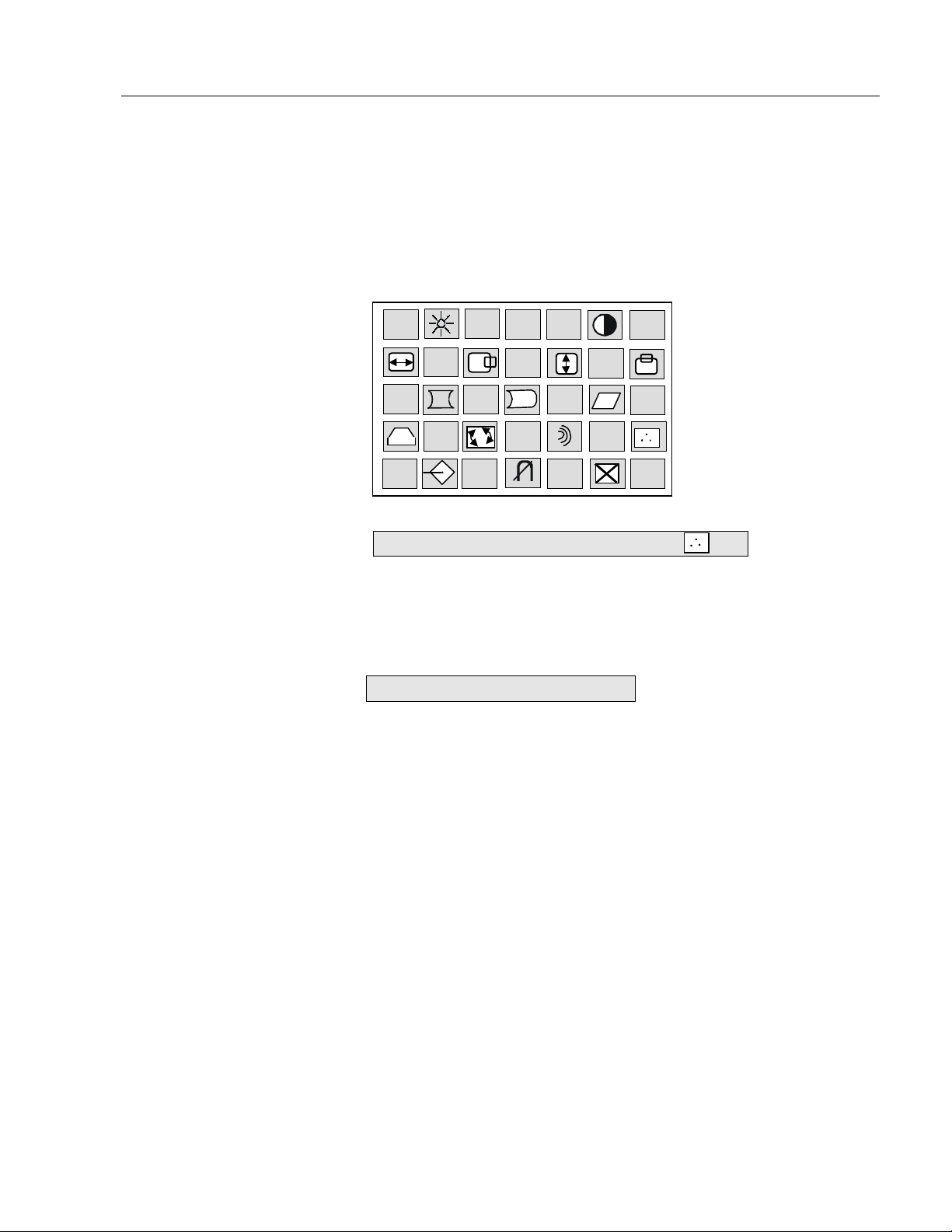
Figure 12
On-Screen Display
You can make all the necessary adjustments by making selections in the
on-sc ree n display using one or all of the operation keys . The f ollow ing
table describes the controls on the on-screen display.
Table D
On-Screen Display Definitions
Publication 6157-UM001A-EN-P
Symbol Control Action
Brightness I ncreases or decreases the intensity
(il luminat ion) of t he im age.
Contrast Increases or decreases the strength
(lightness or di mness) of the i mage.
Horizontal
Sizing
Horizontal
Position
Vertical Sizing Increases or decreases the size of the image
Vertical
Position
Pincushion Adjusts the side pincushion (or barreling)
Pinbalance Adjusts the curvature of the left and right
Increases or decreases the size of the image
horizontally.
Moves images horizontally on screen left (-)
or right (+).
vertically.
Moves images horizontally on screen up (+)
or down (-).
si des of the screen i mag e.
Page 29
Industrial 19" CRT Monitor
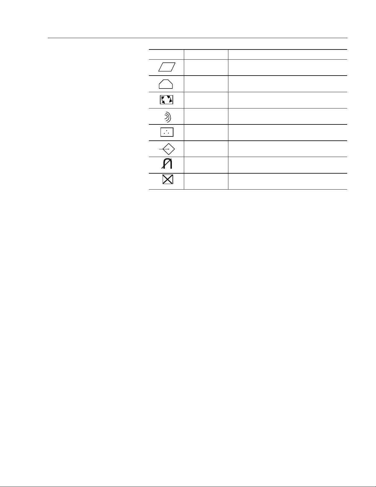
Symbol Control Action
Par all el Cor rects the i mag e shap e to a recta ngle.
Trapezoid Corrects the image shape to a rectangle.
29
Rotation
Color Adjusts the color temperature or white
Recall Resets the display settings to their original
Degauss Demagnetizes the CRTs metal frame for
Exit
Cor rects the scr een ti l t . For exam ple, adjusts
the screen image to be horizontally level.
Reduces the opti cal ef fect of wavy lines on
the display image.
balance of the image.
factory val ues.
improved image clarity.
Select Ex it t o close the o n-sc reen d isplay
main window.
Before a dvancing to these a djustments, you need to underst and t he basic
functions of the operation keys. To aid in this understanding, a sample
procedure is provided below:
Sample Procedure
>
1. Display the on-screen display (OSD) window by pressing
>
2. Press
<
to highlight the variable you want to adjust. Refer to
or
or
<.
Table B.
+
3. Press
or – to adjust the variable.
4. Repeat steps 2-3 for any variables you need to adjust.
>
<
5. Press
6. Press
Note:
+
to select the exit icon from the OSD.
or
or – to exit the OSD.
If you do nothing for ten seconds, the display will
automatically close the window, memorize the settings and
complete the adjustments.
Publication 6157-UM001A-EN-P
Page 30

30
Industrial 19" CRT Monitor
Brightness Control
Use the brightness control to adjust the overall intensity of the display.
After allowing the CRT to warm up for at least a minute, adjust for the
least amount of brightness needed to make the display clearly viewable.
Adjust the brightness to match the brightness level in the room so that
the level will be easy to see.
1. Display the OSD.
2. Use the arro w keys (
3. Adjust the brightness value to its lowest setting. (For example, black
background with no text).
4. Adjust the brightness until black changes to dark gray.
5. Adjust the brightness down until the bar changes back to black. This
is the optimal brightness setting given the current lighting
conditions.
Note:
6. Proceed to make oth er adjustment s as necessary.
Note:
Pressing the arrow keys simultaneously while the
brightne ss a dju st me nt box is display e d sets the s tandard
level.
If you wait ten seconds, the display will automatically close
the window, memorize the settings and complete the
adjustments.
> or <
) to select the brightness adjustment box.
Publication 6157-UM001A-EN-P
Page 31

Industrial 19" CRT Monitor
Contrast Control
Use the co n tr as t co ntrol to adju st the differe n ce between the m onitor’s
light and dar k elements. With a suitabl e imag e displayed on the screen,
adj ust t he c ont rast cont rol to achi eve the bes t b alance be tween image
brightness and fine detail rendition.
1. Display the OSD.
31
2. Use the arro w keys (
Note:
3. Press
conditions.
4. Proceed to make oth er adjustment s as necessary.
Note:
Pressing the arrow keys simultaneously while the
contrast adju st me nt box is displa yed s et s the s tandard
level.
+
or – to adjust t he contrast value given the cu rr ent lig hting
If you wait ten seconds, the display will automatically close
the window, memorize the settings and complete the
adjustments.
> or <
) to select the contrast adjustment box.
Horizontal Position
Use the horizontal position controls to center the image horizontally on
the screen.
1. Display the OSD.
2. Use the arro w keys (
+
– t
3. Press
on your screen.
Note:
4. Proceed to make oth er adjustment s as necessary.
Note:
or
You can use the arrow keys (
the horizontal size and horizontal position control
boxes.
If you wait ten seconds, the display will automatically close
the window, memorize the settings and complete the
adjustments.
> or <
o move the image to the left or right until it is centered
) to select the horizontal position box.
> or <
Publication 6157-UM001A-EN-P
) to toggle between
Page 32

32
Industrial 19" CRT Monitor
Horizontal Size
Use the horizontal size controls to makes the image wider or narrower.
Note:
1. Display the OSD.
2. Use the arro w keys (
3. Press
4. Proceed to make oth er adjustment s as necessary.
Note:
Before adjusting the horizontal size, you must first center
the image in the screen using the horizontal position
controls.
Pressing
horizontal position control boxes.
+
or – narrow or widen the image on your screen.
> toggles between the horizontal size and
> or <
If you wait ten seconds, the display will automatically close
the window, memorize the settings and complete the
adjustments.
) to select the horizontal size box.
Vertical Position
Use the vertical position controls to center the image vertically on the
screen.
Publication 6157-UM001A-EN-P
Note:
1. Display the OSD.
2. Use the arro w keys (
3. Press
screen.
4. Proceed to make oth er adjustment s as necessary.
Note:
Pressing
position control boxes.
+
or – to move the image up or down until it is centered on the
> toggles between the vertical size and vertical
> or <
If you wait ten seconds, the display will automatically close
the window, memorize the settings and complete the
adjustments.
) to select the vertical position box.
Page 33

Industrial 19" CRT Monitor
Vertical Si ze
Use the vertical size controls to make the image taller or shorter.
33
Note:
1. Display the OSD.
2. Use the arro w keys (
3. Press
4. Proceed to make oth er adjustment s as necessary.
Note:
Before adjusting the vertical size, first center the image in
the screen.
> or <
+
or – key heighten or shorte n the image on th e screen.
If you wait ten seconds, the display will automatically close
the window, memorize the settings and complete the
adjustments.
) to select the vertical size box.
Vertical Pincushion
Use the vertical pincushion controls to correct the image for barrel or
pincushion distortion.
1. Display the OSD.
2. Use the arro w keys (
+
3. Press the
4. Proceed to make oth er adjustment s as necessary.
Note:
or – key to straighten the sides of the screen image.
If you wait ten seconds, the display will automatically close
the window, memorize the settings and complete the
adjustments.
> or <
) to select the vertical pincushion box.
Publication 6157-UM001A-EN-P
Page 34

34
Industrial 19" CRT Monitor
Trapezoid
Use the trapezoid controls to correct trapezoidal distortion of the image.
1. Display the OSD.
2. Use the arro w keys (
+
– t
3. Press
screen.
4. Proceed to make oth er adjustment s as necessary.
Note:
or
If you wait ten seconds, the display will automatically close
the window, memorize the settings and complete the
adjustments.
> or <
o make the image w ider or narr ower at t he t op of the
) to select the trapezoid box.
Pinbalance
Use the pinbalance controls to adjust the curvature of the left and right
sides of the screen image.
1. Display the OSD.
2. Use the arro w keys (
+
3. Press
the image until the sides of the image are straight.
or – key to adjust the curvature at the left and right sides of
> or <
) to select the pinbalance box.
Publication 6157-UM001A-EN-P
4. Proceed to make oth er adjustment s as necessary.
Note:
If you wait ten seconds, the display will automatically close
the window, memorize the settings and complete the
adjustments.
Page 35

Industrial 19" CRT Monitor
Parallelogram
Use the parallelogram controls to correct parallelogram distortion of the
image on the screen.
1. Display the OSD.
35
2. Use the arro w keys (
+
3. Press the
4. Proceed to make oth er adjustment s as necessary.
Note:
or – key to skew the image to the left or right.
If you wait ten seconds, the display will automatically close
the window, memorize the settings and complete the
adjustments.
> or <
) to select the parallelogram box.
Rotation
Use the rotation controls to adjust for tilt of the image on the screen.
1. Display the OSD.
2. Use the arro w keys (
3. Press the
4. Proceed to make oth er adjustment s as necessary.
+
or – key to adjust the tilt of the image on the screen.
> or <
) to select the rotation box.
Note:
If you wait ten seconds, the display will automatically close
the window, memorize the settings and complete the
adjustments.
Publication 6157-UM001A-EN-P
Page 36

36
Industrial 19" CRT Monitor
Color Temperature
Use the color temperature controls to adjust the color white in an image
(in Ke l vin ). The higher t he temperature, the red der, or war m er, t h e image
color sc hem e. The lower t he temperature, t h e bluer, o r co ld er, t he image
color scheme.
1. Display the OSD. Press
2. Press
>
<
to move to the color control icon.
or
+
or – to select the color icon. The following appears:
9300K 6500K 5500K
Note:
3. Press
4. Press
screen color adjustment window will appear.
5. Press
+ or –
three color variables.
Before making any ad justments , record t he init ial color
setting because memory recall will not reset this value.
>
or <
+
or – to enter your choice. If you select the color icon, the
> or <
to adjust the selected value. Repeat this step to adjust all
to choose 9300K, 6500K, 5500K, or the color icon.
to select R (red), G (green), or B (blue) and then press
Publication 6157-UM001A-EN-P
6. Press the
return to the OSD main window. The window closes automatically
after ten seconds.
> or <
keys to select the exit icon, then press + or – to
Page 37

Industrial 19" CRT Monitor
Recall
Use this option to reset the display settings to their original factory
values.
1. Display the OSD.
2. Use the arro w keys (> or <) to select the recall box.
+
3. Press the
factory settings.
or – key to reset the display values to their original
Degauss
The display screen is degaussed automatically each time the monitor is
powered on. This degaussing eliminates color impurities and other
distort ions of the display b y neutralizin g the e ffect s of ma gnet i c fie lds i n
the surrounding environment.
37
When the unit is left on for a long period, or is repositioned following
power-up, the screen may pick up additional magnetic flux, causing
colors to appear "blotchy" or otherwise distorted. For full effectiveness,
allow at least 20 minutes between manual degaussings. Shorter intervals
may r es ult i n an incomplet e removal of flux and residual color
impurities.
Note:
Note:
The degauss ing operates f or a pprox imatel y f ive seco nds a fter selecti on.
In this durat ion, t he front panel keys are not oper ati onal.
The internal degauss will not prevent color impurities
caused by local magnetic fields. Metal enclosures can
easily become magnetized by welding and machinery
operations.
Use a hand held degaussing coil to remove residual
magnetism from the enclosure.
If the unit is located near electric transformers, motors,
loudspeakers or other strong magnetic sources, degaussing
alone may not be sufficient to eliminate interference. Try
reorienting the unit relative to the magnetic source or
moving the monitor further away.
If this still does not solve the problem, contact Rockwell
Automation about magnetic shielding.
Publication 6157-UM001A-EN-P
Page 38

38
Industrial 19" CRT Monitor
Exit
Use the ex i t icon on the scree n to close the OSD main window.
1. Display the OSD.
2. Use the arro w keys (
+
3. Press the
Note:
or – key to exit the OSD.
If you wait ten seconds, the display will automatically close
the window, memorize the settings and complete the
adjustments.
> or <
) to select the exit box.
Publication 6157-UM001A-EN-P
Page 39
Industrial 19" CRT Monitor
Routine Maintenance
Cleaning
Occasionally clean the display panel and cabinet with a soft cloth
dampened (not soaked) with a mild (non-abrasive) glass cleaner. Keep
turning a fr es h sid e of the cloth toward the screen s urf ace to avo i d
scratching it with accumulated grit.
39
Note:
Special care should be t aken when cleanin g a tou c hscreen or
polycarbonate shield that is installed over the screen. Abrasive and
certain chemical cleaners can easily damage the surface.
Note:
The solvent should be applied only to the cloth, and not
directly on the monitor screen. Do not use paper products
as they may scratch the surface. To minimize the risk of
abrasion, allow the screen to stand dry.
For best results cleaning a monitor with the optional
antireflective tempered glass display shield, a solution of
denatured alcohol is recommended to thoroughly clean the
display.
Replacing a Line Cord
To avoid shock and fi re hazards, the monitor’s po w er cor d should b e
replaced if the insulation becomes broken or if it develops a loose
internal co nnection.
Fuse Replacement
The 6157- C Industrial Monitor is equipped with one fuse, which can be
replaced by a qualified technician.
A TTENTION:
areas that can present dangerous voltages. Always
disconnect the AC power cord and wait one minute
before attempting fuse replacement. Replace the rear
cover before restoring power to the monitor.
The fuse is located inside the monitor chassis, mounted on the main
board in front of the IEC320 power connector. To access the fuse, you
must remove the rear cover of the unit. Replace the fuse as required with
a 5X20mm , T4AH 250V fuse.
Fuse replacement requires work in
Other Maintenance
Qualified service personnel should perform all maintenance, except for
the power cord replacement described above.
Publication 6157-UM001A-EN-P
Page 40
40
Troubleshooting
Industrial 19" CRT Monitor
You can refer to this table to help identify the cause and offer a solution
to a problem. This table lists typical problems you may encounter.
Table E
Troubleshooting Table
Sympto m Possib le Pr ob l e m Action
No screen image and the green power
LED is not lit.
The green power LED is lit, but no screen
image when power switch is closed.
The amber status LED is lit, and no
screen im ag e.
No raster vis i bl e ev en when brightn ess
and contrast are set full ON.
Raster di m l y vis ib l e wit h br ig ht ness and
contrast controls set full ON, but no
displ ay pr esent
Display is pr esent, but garbled or r olli ng Monitor not s ync h ed to video
Display is present and stable, but appears
“wrapp ed” at on e si d e or oth erw ise not
properly centered or sized.
Display is present and stable, but missing
some color(s)
Display is present and stable, but colors
are not pur e
Power cord not connected.
No power av ail able at AC ou tl et. Test AC outl et b y plu gg ing in a lamp or oth er
Power cord faulty. Replace power cord. Refer to Page 39.
Blown fuse. Have moni tor serviced.
Monitor f aulty. Have moni tor serviced.
Screen saver or power
manag em en t feature act ivated.
Brightness and contrast controls
not proper l y ad jus t ed.
Monitor n ot s ync h ed t o video
sourc e.
Monitor f aulty. Have moni tor serviced.
Monitor ou t of ad jus t m ent or
faulty.
Video cab l e pr ob l em. Check f or pr oper instal l at i on of vi deo cable( s ).
Fault in vid eo s our ce. Test vid eo s our ce by conn ect in g to anoth er
Fault in mon itor. Have moni tor serviced.
sourc e.
Size and pos it i on controls n ot
properly adjusted.
Video cab l e pr ob lem. Check for prop er vi d eo c ab le instal l ation.
Fault in mon itor. Have moni tor serviced.
Monitor requires degaussing. Manually degauss the monitor. Refer to
Enclos ur e r equ ires degaus s ing.
Open power switch. Reconnect power cord at
monitor an d at A C outlet. Cl ose power sw itc h.
known good device.
Disable screen saver by activating an input to the
host sys t em. Pr ess a ke y or m ove the mous e t o
cance l power save mode.
Adjust brightness and contrast controls.
Check f or pr oper video c ab le instal l ati on. Replace
suspected faulty cable.
Check to ens ure that vid eo s ou r ce is operati ng
within th e m oni t or ’s rang e.
Have moni tor serviced.
Refer to installation instructions.
Replace suspected faulty cable(s).
monitor th at is kn own t o b e op erat i on al .
Refer to installation instructions.
Check f or pr oper video c ab le instal l ati on. Replace
suspected faulty cable.
Check to ens ure that vid eo s ou r ce is operati ng
within th e m oni t or ’s rang e.
Adjust c ontrols f or pr op er siz e an d positi on of
displ ay. R ef er to op erator instructi ons
Replace suspected fau lty cable.
Check vid eo s our ce.
Page 37.
Manual l y deg aus s th e enc losure. R ef er t o Pag e
37.
Publication 6157-UM001A-EN-P
Page 41
Sympto m Possib le Pr ob l e m Action
Display is pr esent, but “ jit ters” or is
severely distorted
Do not confuse the flicker
NOTE:
associated with an interl ac ed video m od e
with jitter.
Display is present, but “bars” appear
across it.
Connected monitor to computer. When
powered, the PC locked up
Interf eri ng e xternal AC or DC
magnetic shield
“Noise” generated by other
equipment in the environment is
present at t h e vi d eo inputs
Graphics card driver is not
compatible with monitor
Industrial 19" CRT Monitor
If possible, reposition the monitor beyond the
proximity of large transformers, motors, bus bars,
etc.
Ask Rock w ell A ut om ation ab ou t various shi el di ng
options avai l able to prot ect the mon it or .
Consult the application note that discusses
methods of eli m in ating noise.
Update t h e grap hic s card drivers t o th e lat est
version.
41
Publication 6157-UM001A-EN-P
Page 42

42
Allen-Bradley Support
Industrial 19" CRT Monitor
Allen-Bradley offers support services worldwide, with over 75
Sales/Support Offices, 512 authorized Distributors and 260 authorized
Systems I ntegrators located throughou t th e United States alone, plus
Allen-Bradley representatives in every major country in the world.
Local Product Support
Contact your local Allen-Bradley representative for:
Sales and order support
•
Product technical training
•
Warranty support
•
Support service agreemen ts
•
Refer to the Rockwell Automation/Allen-Bradley Internet site at
http://www.a b. com for local contact information.
Technical Product Assistance
If you need to contact Allen-Bradley for technical assistance, please
review the information in the Troubleshooting section first. Then call
your local Allen-Bradley representative or contact Allen-Bradley
technical support at (440) 646-5800.
For additional product information and a description of the technical
services available, visit the Rockwell Automation/Allen-Bradley Internet
site listed above.
Publication 6157-UM001A-EN-P
Page 43
Industrial 19" CRT Monitor
Description
Setting Up the
$
$SSHQGL[ $
SSHQGL[ $
,QWHUIDFH
,QWHUIDFH
All touch controllers are configured by default to provide serial
communications at 9600 baud, 8 data bits, 1 stop bit, no parity.
For Allen-Bradley monitors equipped with touchscreens, a serial
communications cable is r equ ired. A suitable cable can b e obta i n ed fr o m
Roc kwell Automa ti on or you can c reate one.
The cable provides a communications channel between the touchscreen
controller, which is mounted inside the monitor, and an RS-232-C serial
port on the host computer. Because the touch controller obtains power
from the monitor's power supply, no external touch power connections
are necessary.
7
7RX
RXF
FKVF
KVFU
UHHQ 6
HHQ 6H
HULDO
ULDO
43
Touchscreen Interface
Software supplied with the touchscreen must be loaded on the host
computer to handle communications with the touch controller over the
channel.
Becau se the tou chsc reen e m ulates a mouse, there may be c ompat i bility
issues involving how the touchscreen emulates mouse buttons, especially
multiple buttons. For a complete discussion of these issues and how to
troubleshoot them, refer to the touchscreen documentation.
This section describes how to set up the touchscreen system using the
6157- C Industrial Monitor. Setup involves the following:
Enabling the touchscreen interface
•
Installing the software on the host computer that will handle
•
communications with the touchscreen controller
Performing a calibration
•
Publication 6157-UM001A-EN-P
Page 44

44
Industrial 19" CRT Monitor
Enablin g th e T ouchscr e en Int er f a c e
The 6157- C Industrial Monitor provides a female DE-9 connector on the
rear panel. This connector provides the serial interface for the touch
controller.
Interconnecting wiring to the host serial port connection is shown in the
following table.
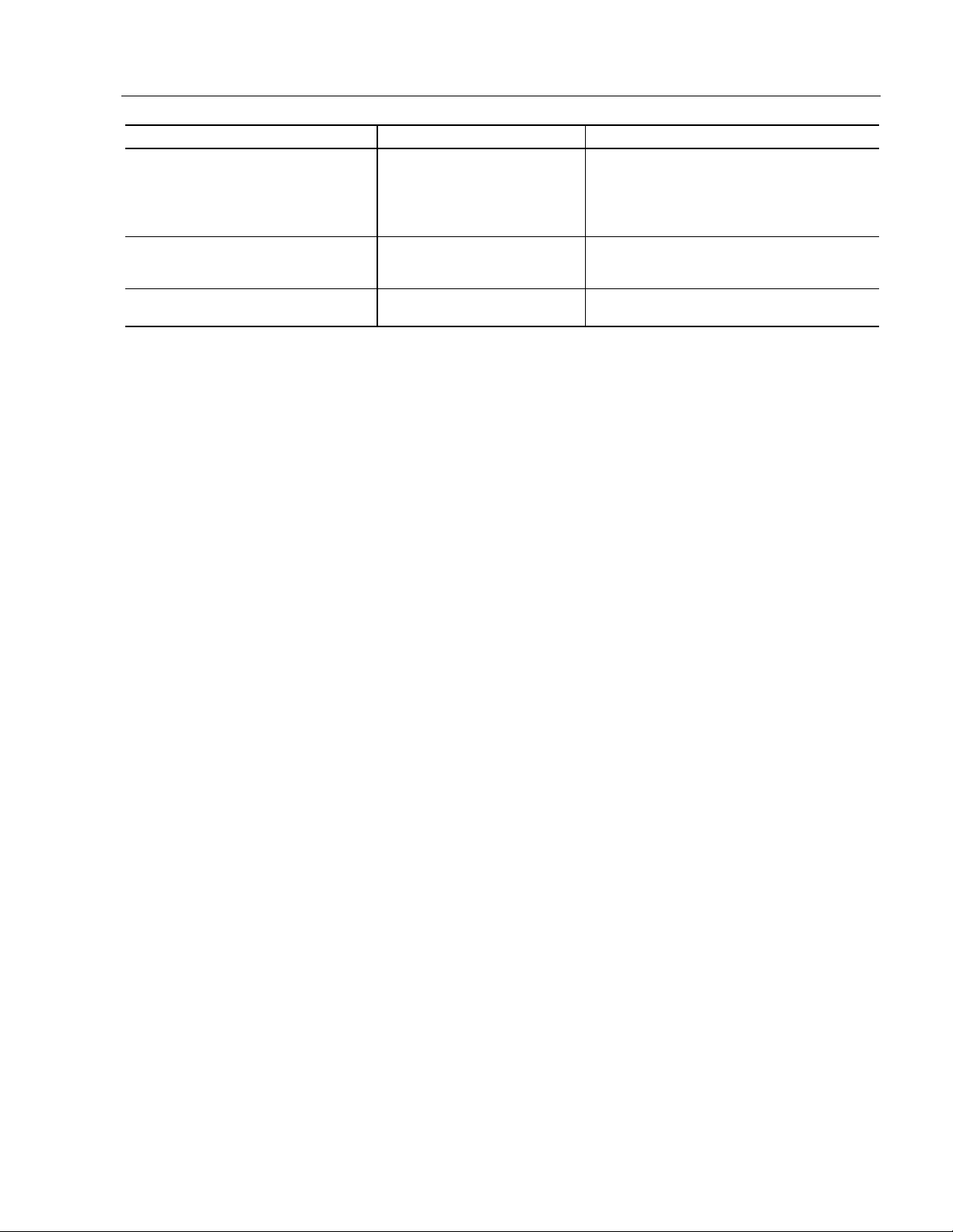
Table F
Touchscreen Interface
Monitor
(DCE Device) Host (DTE Device)
DE-9 (Female) Signal Description DE-9 (Male) DB-25 (Male)
1 Not Connected (DCD) 1 8
2 Transmit Data (TXD) 2 3
3 Receive Data (R XD) 3 2
4 Data Terminal Ready (DTR) 4 20
5 Common Signal Return (SG) 5 7
6 Not Connected ( DSR) 6 6
7 Request To Send (RTS) 7 4
8 Clear To Send (CTS) 8 5
9 Not Connected 9 22
Installing the Touchscreen Driver Software
To install the touchscreen driver software correctly, obtain the following
information about the host hardware:
The COM port in use for the touchscreen. Ensure that the RS-232
•
cable is properly installed between the monitor port and the host’s
COM port.
The baud rat e a t whic h the c o ntroller is operating. You will need to
•
match the baud rate at the COM port. The controller baud rate is
factory set at 9600.
Note:
If you are using older touchscreen software, you may be
prompted for the type of touchscreen controller being used.
The 6157-C uses the following controllers:
Resistive: Elo TouchSystems Model E271-2210
•
Capaciti v e: MicroTouch Model SMT-3
•
SAW: Elo TouchSystems Model 2310 Serial
•
Publication 6157-UM001A-EN-P
Page 45

Industrial 19" CRT Monitor
Performing a Calibr at ion
Once you have obtained this information, install the software using the
installation disks found in the touchscreen accessory package.
45
Note:
Before installation, you may want to check the touchscreen
manufacturer’s site on the World Wide Web for the latest
sof tware dr ivers . E nter thes e ad d res ses in your Internet
browser:
www.elotouch.com for resistive and SAW touchscreens
•
www.microtou ch.co m for capacitive touchscr eens.
•
After installing the driver software, follow the instructions in the
touchscreen documenta t i o n.
Following installation of the touchscreen software and calibration, the
touchscreen is ready to us e.
Publication 6157-UM001A-EN-P
Page 46

46
HD-15 Con ne ct or s
Industrial 19" CRT Monitor
$
$SSHQGL[ %
SSHQGL[ %
You can connect the 6157- C Industrial Monitor to the host computer
with an HD-15 connector or with a BNC to HD-15 adapter cable.
An HD-15 video cable equipped with a conventional HD-15 connector at
each end connects the 6157- C Industrial Monitor to the host computer.
9
9LGHR &
LGHR &D
DEOHV
EOHV
Note:
Figure 13
HD-15 Video Connector
The following table provides the pin numbers and corresponding pin
assignme nts for t he H D - 15 video connector with the DDC2B ca p ability:
Table G
Standard HD-15 Video Cable
Monitor (Fema le) Signa l Description Host (Male)
This figure is the view looking into the pin end of the male
connector or solder term end of the female connector.
1Red Video 1
2 Gr een Vi deo 2
3Blue Video 3
4 Ground 4
5 Ground 5
6 Red Video Ground 6
7 Green Video Ground 7
8 Blue Video Ground 8
9Not Used 9
10 Sync G round 10
11 Ground 11
12 Bi-Direct ional Data (SDA) 12
13 Horizontal Sync 13
14 Vertical Sync (VCLK) 14
15 Data Clock (SCL) 15
Publication 6157-UM001A-EN-P
Page 47

Industrial 19" CRT Monitor
BNC Connectors
The BNC cables you use with this monitor uses a conventional HD-15
connector at the monitor end to connect the 6157- C Industrial Monitor
to the host computer with five BNC connectors:
47
• R, B
, and G: Red, Green, and Blue input connectors to establish
color. T h ese are used for RS-343 analog si gnals .
• HS/CS
: Separate horizontal/composite sync signal from the video
source.
: Separate vertical sync signal from the video source.
• VS
Figure 14
BNC Video Connector
The following table describes the signal types you can use with these
BNC connectors:
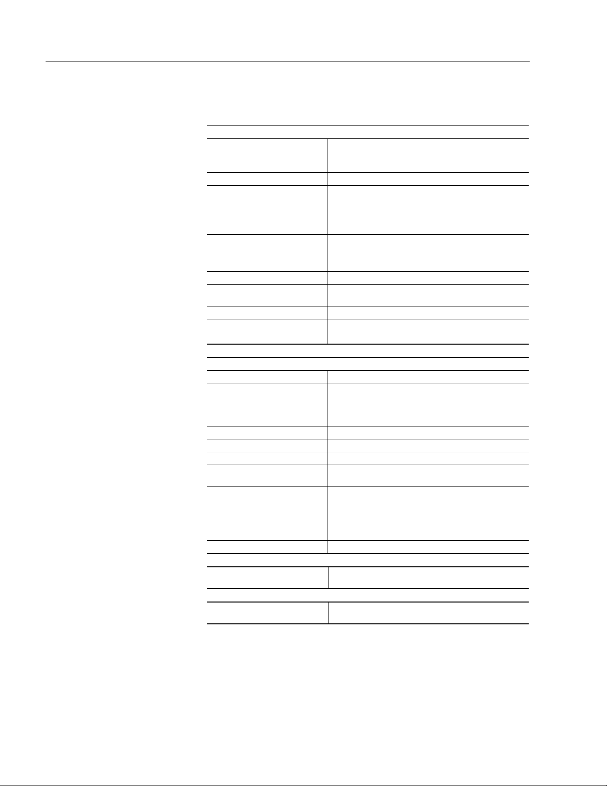
Table H
BNC Signal Types
BNC Signal Type Description R G B HS/CSVS
Sync-on-Green Use the three video connectors. Horizontal
and vertical syncs are supplied on the green
video line.
Separate
Composite Sync
Separate
Horizontal and
Vertical Sync
Use the three video connectors plus the
horizontal sync/composite sync input.
Use the three video connectors plus the
horizontal sync/composite sync and vertical
sync input.
XXX
XXXX
XXXXX
Publication 6157-UM001A-EN-P
Page 48
48
Specific ations
Industrial 19" CRT Monitor
Display
CRT Type 19 in. diagonal pure flat, 0.25mm dot pitch
Degauss in g Manual and au t om at ic
Nominal Displa y Area
(4:3 aspect) Horizontal
(4:3 aspect) Vertical
Diagonal
Non Linearity (CHP Method)
Horizontal
Vertical
Regul ati on 2mm m ax peak de vi ati o n
Misconvergence 0.3mm max inside (centered circle 225mm diameter)
Lumin ance (typical) 35 fL, small wh it e squ are
CIE coordinates
White x:=0.283, y:=0.298 (9300K +8MPCD)
RGB short persistence, Anti-glare treated, Anti-static,
INVAR shadow mask
14.17 in. (360mm)
10.63 in. (270mm)
17.72 in. (450mm)
7% max
6% max
0.4mm m ax ou t s id e
Video
Resolut i on 1600x1200 m ax at 7 5H z ma x
Supported Standards IBM VGA (640x480 at 60Hz, 720x400 @ 70 Hz )
VESA (640x480 at 60/75/85H z, 800x6 00 at
60/75/85 Hz, 1024x768 at 60/75/85 Hz, 1280x1024 at
60/75/85 Hz, 1600x1200 at 75 Hz)
Horizontal Scan Rate Variable: 30-98kHz
Vertical Scan Rate Variable: 50H-160Hz
Video D ot R ate 210MHz
Video Input Signal RGB analog (white level = 0.714V above ref. black,
Sync Input Signals
Input Connection HD-15, Plug and Play DDC1/2B
Controls and Indi cat or s
Operator Input
into 75 Oh ms , sin gl e ended)
Separate horizontal and vertical sync control,
•
TTL signal levels
Sync on green
•
Composite sync
•
Front Panel: On-Screen Display, Power, Sync
detection
Touchscreen Option: Resistive, capacitive, or SAW
touchscreen, with serial controller and driver software
Publication 6157-UM001A-EN-P
Page 49

Industrial 19" CRT Monitor
Environmental
Panel Rating
Panel Mount
Rack Mount
Operati ng Temperat ure 0ºC to 40ºC
Storage Temperature -20ºC to 60ºC
Relati ve Hu midit y 10 % to 90% non-condens i ng
Operati ng Al tit ude S ea lev el to 10,000 ft (3, 04 8 m)
Non-Operating Altitude Sea level to 40,000 ft (12,192m)
Operating Electrostatic
Discharge
Non-Operating Electrostatic
Discharge
Opera ting Shock 10g (1/2 sine, 11msec)
Non-Operating Shock 20g (1/2 sine, 11msec)
Operating Vibration 0.003in. p-p, 5-57Hz,
Non-Operating Vibration 0.006in. p-p, 5-57Hz,
Electrical
Line Volt age 10 0- 1 30 /198-26 4 VA C, au t os witching
Line Frequ ency 50-60H z
Ground Leakage 1.0 uA max at 1.5K VDC
Power Consumption 135W max
NEMA 4/4X/12, (IP65/IP52) (6157-CE/6157-CF)
NEMA 1 (IP10) (6157-CB)
8.0K VDC (IE C 801-2, l evel 3)
20.0K VDC
0.5g peak, 57-640Hz sine
1.0g peak 51-640Hz sine
49
Physical
Panel Mount
Panel Bezel Dimensions
(W x H x D)
Overall Dimensions (from
rear surface of front panel
to back)
Net Weight 64lb (29.0kg)
Rack Mount
Panel Bezel Dimensions
(W x H x D)
Overall Dimensions (from
rear surface of front panel to
back)
Net Weight 64lb (29.0kg)
Certifications - Agency Approvals
LVD (73/2 3/ EEC ) EN 609 50 (per UL 195 0 3rd ed. w ithout D3 d ev. )
EMC (8 9/336/EEC)
Emissions
Immunity
19.0 in. x 15.7 in. x 0.43 in. (483m m x 39 9m m x
11mm)
16.75 in. x 14.0 in. x 18.1 in. (426mm x 356mm x
460mm)
19.0 in. x 15.7 in. x 0.4 in. (482mm x 399mm x 10m m)
16.75 in. x 14.0 in. x 18.2 in. (426mm x 356mm x
462mm)
UL 1950 Recognized Component,
C-UL 950 R ec og ni z ed C om p on ent
EN 50081-2
EN 50082-2
Australia n C-Tick
DHHS
DHHS 21 CFR 1020.10 Compliant
FCC Class A
Publication 6157-UM001A-EN-P
Page 50

IBM is a registered trademar k of In ternational Business Machines Cor poration.
VGA is a trademar k of International Business Mach ines Corporation.
PC AT is a tradem ark of International Business Machines Corporat ion.
Microsoft is a registered trademark of Microsoft Corporation.
Microsoft Windows is a tr ademark of Microsoft Corpor ati on.
Chassis-Trak is a registered trademar k of the General Devices Company.
Rockwell Automati on helps its customers receive a sup erior retu rn on their in vestment b y bri nging
together leading br an ds in i ndustrial autom ation, creatin g a broad spect rum of easy-to-int egrate
products. T hese are supported by l ocal technical resources availabl e worldwide, a global n etwork of
system s olutions provi ders, and the advanced technology resources of Rockwell.
Worldwide representation.
Argentina • Australia • Austria • Bahrain • Belgium • Bolivia • Brazil • Bulgaria • Canada • Chile • China, People’s Republic of • Colombia • Costa Rica • Croatia • Cyprus • Czech
Republic • Denmark • Dominican Republic • Ecuador • Egypt • El Salvador • Finland • France • Germany • Ghana • Greece • Guatemala • Honduras • Hong Kong • Hungary
Iceland • India • Indonesia • Iran • Ireland • Israel • Italy • Jamaica • Japan • Jordan • Korea • Kuwait • Lebanon • Macau • Malaysia • Malta • Mexico • Morocco • The Netherlands
New Zealand • Nigeria • Norway • Oman • Pakistan • Panama • Peru • Philippines • Poland • Portugal • Puerto Rico • Qatar • Romania • Russia • Saudi Arabia • Singapore
Slovakia • Slovenia • South Africa, Republic of • Spain • Sweden • Switzerland • Taiwan • Thailand • Trinidad • Tunisia • Turkey • United Arab Emirates • United Kingdom • United
States • Uruguay • Venezuela
Rockwell Automation Headquarters, 1201 South Second Street, Milwaukee, WI 53204-2496 USA, Tel: (1) 414 382-2000, Fax: (1) 414 382-4444
Rockwell Automation European Headquarters, Avenue Hermann Debroux, 46 1160 Brussels, Belgium, Tel: (32) 2 663 06 00, Fax: (32) 2 663 06 40
Rockwell Automation Asia Pacific Headquarters, 27/F Citicorp Centre, 18 Whitfield Road, Causeway Bay, Hong Kong, Tel: (852) 2887 4788, Fax: (852) 2508 1846
World Wide Web: http://www.ab.com
998078-010
Publication 6157-UM001A-EN-P
Copyright 2000 Rockwell Automation Corporation. All rights reserved. Printed in USA.
•
•
•
 Loading...