

Page 1
Industrial 20" CRT Monitor
(Bullet in 61 57)
Installation and User Manual
Page 2
2 Table of Contents
7
7D
DEOH R
EOH RI
Industrial 20" CRT Monitor.............................................. 3
Description........................................................................... 3
Package Contents................................................................. 4
Installing the 6157 Industrial Monitor ................................... 5
Panel Mounting.................................................................... 6
Connecting the 6157 Industrial Monitor................................ 12
Operating the 6157 Industrial Monitor.................................. 16
Routine Maintenance............................................................ 20
Troubleshooting................................................................... 23
Appendix A: Touchscreen Serial Interface........................ 25
Description........................................................................... 25
Setting Up the Touchscreen Interface.................................... 25
Performing a Calibration...................................................... 27
Appendi x B : Video Ca bl es ................................................. 28
HD-15 Connectors ............................................................... 28
BNC Connectors.................................................................. 29
Specifications...................................................................... 31
I &RQWH
&RQWHQ
QWV
WV
Important U s er Information
Solid state equipment has operational characteristics differing from those of
electromechanical equipment. "Safety Guidelines for the Application, Installation, and
Maintenance of Solid State Controls" (Publication SGI-1.1) describes some important
differences between solid state equipment and hard-wired electromechanical devices.
Because of this difference, and because of the wide variety of uses for solid state
equipment, all persons responsible for applying this equipment must satisfy themselves
that each intended application of this equipment is acceptable.
In no event will Rockwell Automation be responsible or liable for indirect or
consequential damages resulting from the use or application of this equipment.
The examples and diagrams in this manual are included solely for illustrative purposes.
Because of the many variables and requirements associated with any particular
installation, Rockwell Automation cannot assume responsibility or liability for actual
use based on the examples and diagrams.
No patent liability is assumed by Rockwell Automation with respect to use of the
informat ion, cir cuits, equipment, or s of twar e described in this manu al.
Reproduction of the contents of this manual, in whole or in part, without written
permission of Rockwell Automation is prohibite d.
Throughout this manual, we use notes to make you aware of safety considerations.
ATTENTION: Identifies information about practices or
circumstances that can lead to personal injury or death,
property damage, or economic loss.
Important:
application and understanding of the product.
Identifies information that is espe cially imp ortant for succe ssful
Publication 6157-5.1
Page 3
,QGXVWULDO
,QGXVWULDO
&57 0RQLW
Industrial 20" CRT Monitor 3
&57 0RQLWR
RU
U
Description
The Bulletin 6157 20" Industrial CRT Monitor is a general purpose
monitor suitable for a wide range of industrial computing applications. It
offers the following features:
• Versatile multi-sync interface (640 x 480 to 1280 x 1024 resolution)
• High-contrast INVAR mask tube
• Reliable and rugged industrial design
• Durable NEMA 4/4X/12 front panel
• Full y- i nt egrat ed dig it a l des ig n
• Microprocessor communications port for remote control of all
monitor functi ons.
ATTENTION: The equipment described in this
document generates, uses, and emits radio frequency
energy. The equipment has been t ested and found to
comply with FCC Rules, Part 15, subpart J, for Class A
computing devices.
The use of non-shielded interface or power cords with
All e n-Bradley indust rial monitor s is prohibited.
ATTENTION: X-ray emissions from these monitors are
typically about 0.05 mR/hr maximum, well below the 0.5
mR/hr maximum rec ommend e d by the US. Departme nt of
Heal th and Human Resour ces an d specif ied i n "Federal
Perf orman ce Standar ds for Television R e ceiv ers", Section
10, Part 1020, Title 21, of the U. S. Code of Regulation
(PL90-620), Vol. 38, No. 198.
These m onitors are equip ped wit h X-ray protection
circuits which cause automatic shutdown of the
equipment i n cas e its X-r ay emissions begin to ap pr oach
Feder al limits .
Publication 6157-5.1
Page 4

4 Industrial 20" CRT Monitor
Availab l e O pt ions
The following options are available to the 6157 Industrial Monitor:
Video interface options (HD-15, 5 BNC)
•
Touchscreen options (r esist i v e, ca p acitive)
•
Touchscreen cable optio ns
•
Video ca ble options
•
Power cord options
•
Magnetic shield options
•
Package Contents
The monitor shipping carton contains the following items:
Monitor
•
Pa cka g e of mou nt i ng ha r dwa r e
•
AC power cord (optional)
•
Video cable (optional)
•
This user manual
•
A 6157 Industrial Monitor with a touchscreen option is shipped with
these additional items:
Supporting software and manuals
•
RS-232 serial extension cable (optional)
•
Un packing the Unit
Before unpacking a new monitor, inspect the shipping carton for
damage. If damage is visible, immediately contact the shipper and
request assistance. Otherwise, proceed with unpacking.
Publication 6157-5.1
Note:
Make s ure you keep t he ori ginal packagin g f or the monitor
in case you need to return the monitor for repair.
Page 5

Industrial 20" CRT Monitor 5
Installing the 6157 Industrial Monitor
This section describes how to install the monitor.
Tools Needed
In addition to the tools required to make the cutout, you will need the
following tools:
3/8” Deep Well Socket
•
1/4” Drive Extension - 12” or longer
•
1/4” Drive Ratchet or 1/4” Drive Torque Ratchet
•
Before Installation
When installing the unit, it is important to consider environmental
factors at the site that could affect performance as well as possible
effects from equipment operation on personnel and nearby equipment.
Following the guidelines will help ensure that the monitor will provide
safe and reliable service.
Ensure that sufficient power is available from a single phase AC
•
outlet at the site.
Ensure that sufficient space is available around air inlets and outlets
•
to provide the circulation necessary for cooling. Never allow air
passages to become obstructed. The monitor is equipped with a fan
to ensure proper cooling.
• Dust and smoke part icl es ca n ca us e pr obl ems , s ince they can collect
at ventilating holes in the enclosure and interfere with cooling.
Accordingly, wh ere dust and smoke are probl ems it is esp ecia lly
important to keep air vents clean. Refer to the Routine Maintenance
section (Page 20) for more information.
Ensure that the ambient air temperature will not exceed the
•
specified maximum temperature. A user supplied fan, heat exchanger
or air conditioner may be required to meet this condition in some
installations.
Leave the m onitor’s enclosure or cover in place at all times during
•
oper ation. The c over affords prote c tion agai nst hig h voltages inside
the monitor and inhibits radio-frequency emissions that might
interfere with other equipment.
The Federal Communications C ommission has prepa red a pamphlet
•
that addr esses the pr ob lem of radio frequency interference to radio
and televisio n receptio n, which should b e consu lted i n c ase of
problems with such interference. This publication, “How to Identify
and Resolve Radio/TV Interference Problems” (Stock #004-00000345-4) may be obtained from the US. Government Printing Office,
Washington, DC 20402.
Publication 6157-5.1
Page 6
6 Industrial 20" CRT Monitor
Determine the mini mum and maximum ambient humidity for the
•
monitor by consulting the specification sheets at the back of this
manual. Ensure that the humidity of the ambient air will not exceed
these limits. In very dry environments, static charges build up very
rea dily. Proper groundi ng of t he equ ipment through th e AC pow er
cord can help reduce the likelihood of static discharges, which may
cau se shoc ks and damage e lectronic c omponents.
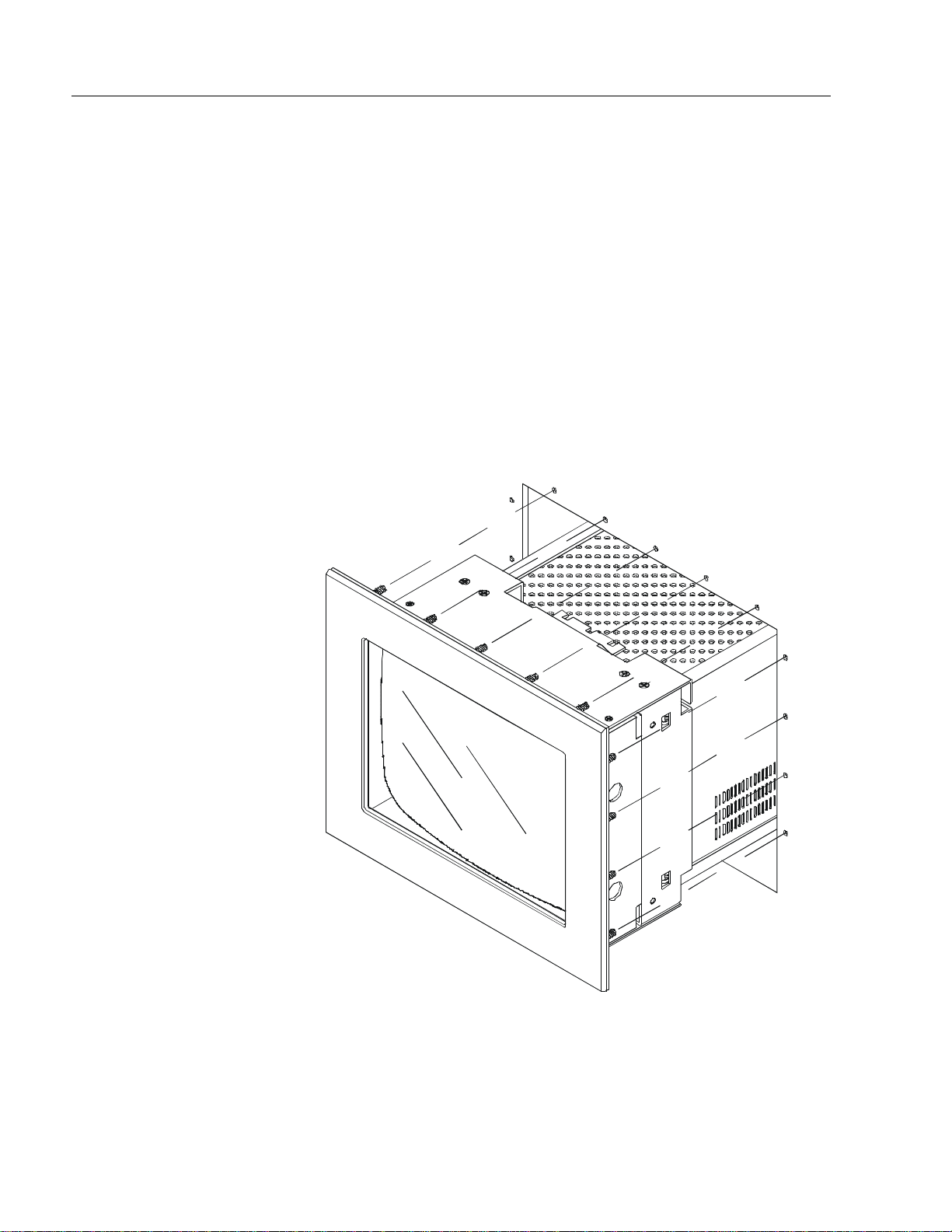
Panel Mounting
When properly installed, the 6157 Industrial Monitor is designed to
pr ovide prot ection agai nst wa ter a nd dust to NEMA 4, NEMA 4X
(plastic panel), and NEMA 12 standards.
No slides or shelves are required because the 6157 Industrial Monitor is
designed to be supported by the panels in which it is installed.
Figure 1
Generic Panel Mount Diagram
Publication 6157-5.1
Page 7
Industrial 20" CRT Monitor 7
Panel Mounting Guidelines
Observe the following precautions before installing the unit in a panel:
Confirm that there is ad eq uate spac e behind the p anel. Rememb er to
•
allow extra space (3 in. (76.2 mm) behind and 1 in. (25.4 mm) below
and on each side) for air circulation.
Confirm that the cabinet is deep enough to accommodate the
•
monitor's depth while providing rear clearance for airflow. A cabinet
with depth of 23.11 in. (587 mm) is sufficient.
Take precautio ns so tha t meta l c utti ngs do not enter any c ompone nts
•
that are already installed in the panel.
Supporting panels should be at least 14 gauge to ensure proper
•
sealing against water and dust and to provide proper support. The
mounting hardware supplied accommodates panels up to 0.25 in.
(6.35 mm) thick.
Note:
Supporting panels must be cut and drilled to
specifications prior to installation.
ATTENTION: Failure to follow these warnings may
result in personal injury or damage to the panel
components.
Publication 6157-5.1
Page 8
8 Industrial 20" CRT Monitor
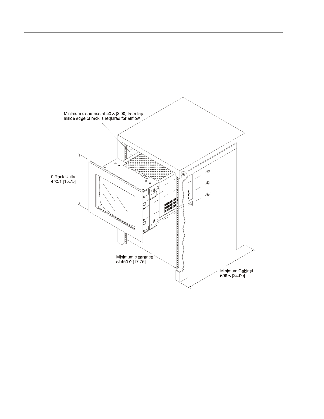
Mounting the 6157 Industrial Monitor in a Rack
Due to the front panel size and stud pattern, the 6157 Industrial Monitor
can be installed in an EIA 19” 9U panel standard rack. Refer to the
following figure:
Figure 2
Generic Rack Mounting Diagram
Publication 6157-5.1
Important:
If you install the 6157 Industrial Monitor in a rack, you
must ensure that the rack can support the weight of the
monitor.
You might need to install a support or shelf under the rear
of the monitor to support the weight.
Page 9
Industrial 20" CRT Monitor 9
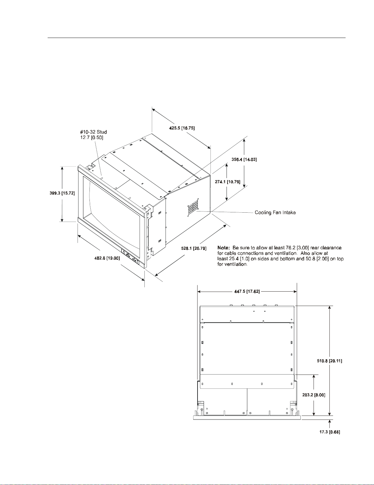
Dimensions
This section provides diagrams you need to follow to install the unit.
Figure 3
6157 Industrial Monitor Dimensions
Publication 6157-5.1
Page 10
10 Industrial 20" CRT Monitor
Panel Mounting Procedure
1. Confirm that the shipping carton contains a package of 20 10-32 lock
nuts and 20 flat washers. You will ne e d 18 nut s and washers for
installation.
2. Refer to th e physic al dimension drawing ( Figure 3) and confir m t hat
th ere is adequate spa ce be h ind the pane l. R emember to a l low extra
space for c i rculation and cabli ng.
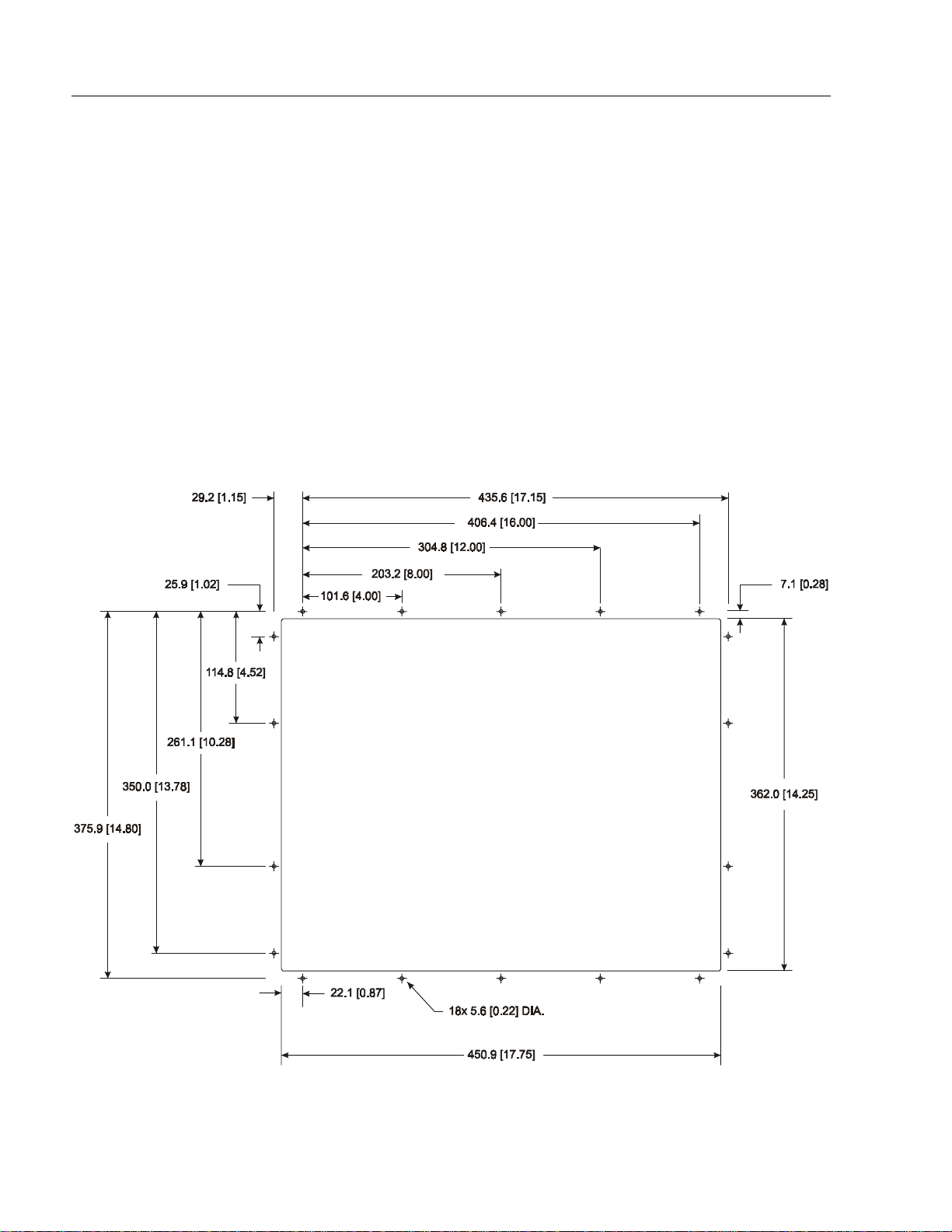
3. Refer to the panel cutout drawing below for dimensions of the panel
cutout and mounting hole locations. Cut and drill the panel.
Note:
Figure 4
Panel Mounting Cutout
Use #10-32 or M5 self-locking nuts for mounting.
Publication 6157-5.1
Page 11

Industrial 20" CRT Monitor 11
4. Carefully remove the monitor from its packaging. Avoid damaging
the monitor gasket.
Tip: It will be easier to install the monitor if you support it with a shelf
or other support adjusted to the appropriate height.
5. Insert the monitor in the panel cutout from the front. Do not damage
the threaded mounting studs as you position the monitor.
6. Secure the unit with the lock nuts and washers provided. Tighten
evenly to 24 inch-pounds of torque.
Important:
To ensure a proper seal, be sure to install a washer and
nut on each of the 18 mounting studs.
ATTENTION: Mounting nuts must be tightened to a
torque of 24 inch-pounds to provide panel seal and
avoid potential damage. Rockwell Automation
assumes no responsibility for water or chemical
damage to the monitor or other equipment within the
enclosure due to improper installation.
7. Remove the protective adhesive sheet from the screen of the
Industrial Monitor. The sheet is designed to prevent scratching of
the polycarbonate screen protector or the optional touchscreen
during shipping and installation. It should be removed before use.
Publication 6157-5.1
Page 12

12 Industrial 20" CRT Monitor
Connecting the 6157 Industrial Monitor
The rear panel of the 6157 Industrial Monitor has connectors for
attaching cables to accomplish the following:
Connecting to a host video source (HD-15 VGA or BNC connectors)
•
Connecting to a host t ouchscreen control port (DB-9 connector)
•
(optional)
Connecting to AC power
•
Note:
Some connectors on your monitor may differ from the
following figure.
The following figure illustrates the standard configuration for the 6157
Industrial Monitor.
Figure 5
Rear Panel
Publication 6157-5.1
Page 13

Industrial 20" CRT Monitor 13
Connecting the Video Source
The video connection to the host is made through a HD-15 (female)
connector or through BNC input connectors.
To establish a signal using the HD-15 connector:
Note:
For more information on using an HD-15 video cable to
connect to the host computer, refer to Appendix B
(Page 28).
1. Obtain a shielded, properly terminated video cable of length as short
as possible. Longer cables (up to approximately 50 feet in some
cases) may be used, provided they are properly constructed. Your
package may include a six-foot video cable, if specified.
2. Connect one end of the cable to the female HD-15 video input
connector on the rear panel of the monitor.
3. Conn e c t the other en d to th e ou tput of any IBM-co mp atible VGA
ada pter or other vide o generator.
Note:
You may connect the monitor to video generators that
do not conform to VGA standards. The main
requirement is that the generator provide analog RGB
video signals (0.714V above reference black into 75
ohms) and separate horizontal and vertical sync signals.
To establish a signal using the BNC connectors:
Note:
For more information on using BNC connectors, refer to
Appendix B (Page 29).
1. Obtain 75 ohm coaxial cables fitted with BNC connectors. Make
su re the ca bles are of eq ual length.
Note:
An HD-15 to BNC video cable is available from
Rockwell Automation for connecting the monitor to a
VGA video source.
2. Connect one end of the cable to the appropriate BNC input
connectors (R, G, B, HS/CS, VS) on the rear panel of the monitor.
3. Connect the other end to the corresponding output of any video
source. For example, connect the red output cable from the host to
the red input connector on the monitor.
Publication 6157-5.1
Page 14

14 Industrial 20" CRT Monitor
Connecting the Configuration Port
The 6157 Industrial Monitor is equipped for remote control by the host
computer. You can use the serial configuration port to provide bidirectional communication between the monitor and the host computer.
The host computer can send commands to the monitor requesting
information about the monitor’s status or to adjust monitor operating
conditions.
Note:
Please contact Technical Support for more information on
using the configuration port.
To connect the configuration port:
1. Obtain a “straight” wired serial cable (RS-232) with a 9-pin D-shell
connector.
2. Connect one end of the serial cable to the CONFIG port connector
on the rear of the monitor.
3. Conn e c t the other en d to any serial communications port on th e host
computer.
4. Tighten the captive screws on the cable connector to secure it.
Connecting the Touchscreen Interface
The serial touc hscreen interfa ce connection to th e host is made through
an RS-232 DB-9 (female) connector located on the rear panel.
The optional touchscreen provides a high-resolution touch input system.
Driver software included with the package allows the touchscreen to
function with many popular DOS and Windows
applications as a pointing device (mouse).
®
-based industrial
Publication 6157-5.1
Note:
Refer to the manual included with the touchscreen option
and Appendix A of this manual (page 25) for additional
details on the installation and operation of the touchscreen.
Page 15

Industrial 20" CRT Monitor 15
To connect the touchscreen:
1. For units with the touchscreen option, make sure you have one of the
opti onal serial c ables.
2. Connect one end of the touchscreen serial cable to the T/S port
connector on the rear of the monitor.
3. Conn e c t the other en d to any serial communications port on th e host
computer.
4. Tighten the captive screws on the cable connector to secure it.
Connecting AC Power
The 6157 Industrial Monitor requires a single phase power supply
providing 90 to 264V AC at 47 to 70 Hz. Power must be available at a
grounded three-pi n outlet locate d nearby. Whenever possible, connect
the monitor to the same AC source that supplies the computer.
To connect AC power to the monitor:
1. Turn off the mai n switch or breaker.
2. Use the ground terminal of the monitor to establish a chassis-to-earth
ground connection. Secur e one en d of a grou nd strap t o the ground
termina l. Conne ct th e other end of t he ground strap to a good earth
ground.
The ground terminal is an M5 screw.
A TTENTION: Chassis ground must be connected for
safe operation of the monitor. The AC receptacle on the
monitor is a 3-wire type with chassis ground pin, and the
mating AC cord supplied is a 3-wire type, designed for
connection to a grounded 3-pin AC outlet. However, a
properly ground AC ou tlet is not always avai lable, and
grounding using a 3-wire cord can easily be defeated. If
you fail to ground the monitor properly, the setup may
resu lt in p ersona l injury fro m e lectric al shock or damage
to the equipment.
3. Connec t the socket end of t he AC power cord to the mat ing
connector on the rear panel of the monitor.
4. Connect the plug end of the AC power cord to the main outlet.
5. Restore AC power to the outlet.
Publication 6157-5.1
Page 16

16 Industrial 20" CRT Monitor
Operat i n g th e 6157 Industrial Monitor
This section describes how to operate the 6157 Industrial Monitor.
Controls
The f o llowi n g is a summary of the controls and indicators on the
membrane keypad on the 6157 Industrial Monitor:
Figure 6
Monitor-Re sident Control s
Note:
The number of controls supported by the monitor may vary
depending on the monitor type or customer-specified
options.
Status LED Indicators
The keypa d includes seven green L ED in dicators and one amber LED
indicator. These provide information about the current status of the
monitor.
When the monitor is operating in normal mode, one of the green LEDs
will be lit. The monitor indicates an error condition if more than one
gre e n L E D is lit, or if only the amb er SCF LED is lit.
Note:
Saving Changes
When you finish adjusting the monitor’s settings, the monitor
automatically saves your changes. Approximately 20 seconds after you
stop pressing controls, the amber SCF LED blinks twice to indicate that
your changes were saved.
For information on troubleshooting the 6157 Industrial
Monitor, refer to Page 23.
Publication 6157-5.1
Page 17

Industrial 20" CRT Monitor 17
Manual Degauss
The monitor is equipped with an automatic degaussing system to remove
residual magnetism from the CRT’s shadow mask at power-up.
Degaussing helps keep the screen free of any color impurities which
might otherwise result from magnetism picked up by the shadow mask
from the earth’s magnetic field when the monitor is moved.
In addition, a degauss push button is provided on the control panel. This
manual control can be us e d if col or impurities appear on the screen wh ile
the monitor is in operation.
Note:
Tip: For best results, perform a manual degauss only after allowing at
least 15 minutes to pass following power-up or a previous manual
degauss.
The internal degauss will not prevent color impurities
caused by local ma g netic fields. Metal encl osu res can
easily become magnetized by welding and machinery
operations.
Use a hand held degaussing coil to remove residual
magnetism from the enclosure.
Brightness and Contrast
The 6157 Industrial Monitor is equipped with adjustable brightness and
contrast c o ntrols. Th ese controls are located on the front panel of the
unit.
To obtain the best display, first set the brightness control to the
appropriate setting under the lighting conditions in which the monitor
will be used. Then adjust the contrast control to increase or decrease the
intensity of the video imag e as required.
To set the brightness and contrast controls:
1. Press the Select Mode button until the status LED indicator below
the Brightness icon is lit.
Note:
2. Use the left arrow button to adjust the brightness value to its lowest
setting.
3. Use the right arrow button to adjust the brightness until the black
colors in the screen image change from black to dark gray.
For best results, display a screen image with a large
black area before setting these controls.
Publication 6157-5.1
Page 18

18 Industrial 20" CRT Monitor
4. Use the left arrow button to lower the brightness until the dark gray
colors change back to black. This is the optimal brightness setting
given the current lighting conditions
5. Press the Select Mode button until the status LED indicator below
the Contrast icon is lit.
6. Use the left and right arrow buttons to change the value for the
contras t contr ol to achieve t he appropr iate level of i ntensity in t h e
image.
Horizontal and Vertical Size and Position
The mo nitor is fa c tory preset and normally requires no manual
adjustment for vertical or horizontal alignment. However, four
adjustable size and position contr ols are provide d to permit adjustment if
it should become necessary.
To change size or position:
1. Press the Select Mode button until the status LED indicator below
the a p propriate icon is lit .
2. Use the left and right arrow buttons to change the value for the
selected control.
Raster Rot ation
A ra ster rotation contro l allows for c orrectio ns to any disp lay
misalignment which might be present as a result of interaction between
the monitor and an external, low-level uniform magnetic field, such as
th e ea r t h ’s ma g netic fi e l d.
All C RT displays are affe c ted by the earth’s magn etic fi e ld and by
simi lar low level uniform fields. Ge nerall y, th e eff e c ts of su ch a field on
the display vary with the display’s spatial orientation relative to the field
lines. For example, wh en th e unit’s screen is faci n g west, t h e effects of
the earth’s field are minimal. When the screen is rotated toward the north
or south, the disp lay ca n exhibit a small amount of rota tion, so that its
top and bottom edges are no longer parallel to the edges of the panel.
Note:
This effect is differ ent from the effect of magn etis m on th e
shadow mask, which takes the form of color impurity and is
corrected b y th e d egau s s ing system.
Publication 6157-5.1
Before making any adjustments, display a f ull scre e n image a n d chec k
for rotation (top or bottom edge of the image out of parallel with the
corresponding edge of the panel).
Page 19

Industrial 20" CRT Monitor 19
To change raster rotation:
1. Press the Select Mode button until the status LED indicator below
the raster rotation icon is lit.
2. Use the left and right arrow buttons to adjust the rotation.
Important:
The raster rotation control cannot correct for the effects of
external AC fields such as those produced by large motors,
generators a nd trans formers. Such eff ects often take the
for m of display jitter. Protectio n agai nst this kind of
magn etic interf erence requires sp ecial sh ieldin g.
Secondary Control Function Mode (SCF) for Vertical
Pincushion
The 6157 Industrial Monitor allows you to adjust the vertical pincushion
to straighten the sides of the screen. You adjust the vertical pincushion
by switching the monitor to sec ondary control function mode.
To change the vertical pincushion:
1. Press the arrow buttons simultaneously to enter secondary control
function mode.
The SCF status LED indicator and the brightness LED indicator are
lit to indicate secondary control function mode.
2. Use the left and right arrow buttons to adjust the value.
Note:
3. Press the arrow buttons simultaneously to exit secondary control
function mode.
To best observe the effects of the vertical pincushion
adjus tment, disp lay an approp riat e full-sc reen i mage on
the monitor.
Publication 6157-5.1
Page 20

20 Industrial 20" CRT Monitor
Routine Maintenance
Cleaning
Occasionally clean the display panel and cabinet with a soft cloth
dampened (not soaked) with a mild (non-abrasive) glass cleaner. Keep
turning a fresh s ide of the cloth t owar d the screen surface to a void
scratching it with accumulated grit.
Note:
Special ca re shou ld be taken when cl eanin g a resistive touc hscr e e n or
polycarbonate shield that is installed over the screen. Abrasive and
certain chemical cleaners can easily damage the surface. Never use
alcoholic or ammoniac cleaners.
The solvent should be applied only to the cloth, and not
directly on the monitor screen.
Do not use paper products as they may scr atch the surfac e.
To minimize the risk of abrasion, allow the screen to
sta nd dr y.
Publication 6157-5.1
Page 21

Industrial 20" CRT Monitor 21
Fuse Replacement
The Bulletin 6157 Industrial Monitor is equipped with two AC line fuses
housed in the IEC connector (2.5A 250V). To access the fuses, you must
remove the rear cover of the unit.
A TTENTION: Fuse replacement requires work in
areas that can present dangerous voltages. Always
disconnect the AC power cord and wait one minute
before attempting fuse replacement. Replace the rear
cover before restoring power to the monitor.
To replace the fuses:
1. Disconnect the power cord and remove all other cables attached to
the monitor.
2. Remove the four screws that secure the rear panel of the monitor
using a Philips screwdriver. Refer to the following figure.
Figure 7
Fuse Replacement
3. Remove the rear panel to expose the rear section of the AC input
connector. Pull off the plastic ca p , situated at the rear of t he AC
connector, to expose the fus es.
Publication 6157-5.1
Page 22

22 Industrial 20" CRT Monitor
4. Remove each fuse by inserting the tip of a small flat-bladed
screwdriv er bet w een t h e fuse clip and the metal end cap of the fuse
and gently prying the fu se out of its c lip.
5. Replace each fuse as required with a 5ST Slo-Blo type fuse rated at
2.5A, 250VAC.
6. After replacing each fuse in its clip holder, reinstall the plastic cover
over the fuses, reinstall the rear panel of the mon itor, and recon nect
the AC power cord.
Note:
If a fuse continues to blow, consult a qualified service
technician.
ATTENTION: To avoid danger of fire, always
replace the fuse with one of the same type and rating.
Replacing a Line Cord
To avoid s hock and fire haza rds, the moni tor’s power cord should be
replaced if the insulation becomes broken or if it develops a loose
internal conne c tion.
Other Maintenance
Qualified service personnel should perform all maintenance, except for
the fuse and power cord replacement described above.
Publication 6157-5.1
Page 23

Industrial 20" CRT Monitor 23
Troubleshooting
You can refer to this table to help identify the cause and offer a solution
to a problem. This table lists typical problems you may encounter.
Table A
Troubleshooting Table
Symptom Possible Proble m Action
None of the sta tus LEDs are lit. Power cord not connected.
No power available at AC outlet. Test AC outlet by plugging in a lamp or other
Blown fuse. Replace fuse. Refer to Page 21.
Power cord faulty. Replace power cord. Refer to Page 22.
Monitor f aulty. Have moni tor servic ed.
One green status LED is lit, but no screen
image when power switch is closed.
More than one green status LED is lit, but
no screen image.
The amber SCF status LED is lit and one
green status LED is lit.
Only the amber SCF status LED is lit, and
no screen image.
No raster vis i ble even when br ig ht ness
and contrast controls are set full ON.
Raster di m l y vis ib l e wit h br ig htness and
contrast controls set full ON, but no
displ ay present
Display is pr esent, but gar bl ed or r olling Monitor n ot s ynched to video
Display is present and stable, but appears
“wrapp ed” at on e si d e or oth er wise not
properly centered or sized.
Screen saver activated.
Brightness and contrast controls
not proper l y ad jus ted.
Monitor ou t of ad jus t ment. Turn monit or OF F an d t h en tur n bac k ON .
Monitor is in secondary control
functi on m od e.
Monitor n ot s ynched to video
sourc e.
Monitor f aulty. Have moni tor servic ed.
Monitor ou t of ad jus t ment or
faulty.
Video cable problem.
Fault in vid eo s our ce. Test vid eo s our ce by connect in g to an other
Fault in monitor. Have monitor serviced.
sourc e.
Size and pos it ion controls n ot
proper l y adj us t ed.
Open power switch. Reconnect power cord at
monitor an d at AC out l et . Close power sw itc h.
known good devic e.
Disable screen saver by activating an input to the
host system.
Adjust brightness and contrast controls.
Press both arrow buttons simultaneous l y to exit
secondary control function mode. Refer to
Page 19.
Check for proper video cable installation. Replace
suspected faulty cable.
Check to ens ure that video s ource is oper ating
within th e m oni t or ’s r ang e.
Have moni tor servic ed.
Check f or pr oper install ation of video c abl e( s ).
Refer to installation instructions.
Replace suspected faulty cable (s).
monitor that is known to b e operational.
Refer to installation instructions.
Check for proper video cable installation. Replace
suspected faulty cable.
Check to ens ure that video s ource is oper ating
within th e m oni t or ’s r ang e.
Adjust c ontrols for pr op er siz e an d p osit ion of
displ ay. R ef er t o op erator instr uc ti ons
Publication 6157-5.1
Page 24

24 Industrial 20" CRT Monitor
Symptom Possible Proble m Action
Display is present and stable, but missing
some co lor(s)
Display is present and stable, but colors
are not pur e
Display is pr esent, but “jit ters” or is
severely distorted
Do not confuse the flicker
NOTE:
associated with an in t erlaced vid eo m od e
with jitter.
Display is present, but “bars” appear
across it.
Connected monitor to computer. When
powered, the PC locked up (For units
using th e HD-15 only)
Video cable problem. Check for proper video cable installation.
Fault in monitor. Have monitor serviced.
Monitor requires degaussing.
Enclos ure requires d egaussin g. M anu al ly degauss the enclosur e. R ef er t o
Interf eri ng external AC or DC
magnetic shield
“Noise” generated by other
equipment in the environment is
present at t h e vi d eo inputs
Graphics card driver is not
compatible with monitor
If using BNC inputs, test monitor as follows.
Disconnect sig nal cable(s) corresponding to the
missing color(s). Disconnect signal cable
corresp onding to a disp l ay ed c ol or an d c onn ect it
to the input( s) corresponding to the missing
color(s). If a missing color reappears, the signal
cable corresponding to that color is faulty;
otherwise, the monitor is faulty.
Replace suspected faulty cable.
Manually degauss the monitor. Refer to
Page 17.
Page 17.
If possible, reposition the moni tor beyond the
prox imity of large transformers, motors, bus bars,
etc.
Ask Roc k well A ut om ation abou t various shi el ding
options avai l ab le to protect th e mon it or .
Consult t h e app lication note which disc us ses
method’s of eliminating noise.
Update t h e graphics card dri ver s to th e latest
version.
Publication 6157-5.1
Page 25

$
$SSHQGL[ $
SSHQGL[ $
,QWHUIDFH
,QWHUIDFH
Industrial 20" CRT Monitor 25
7
7RX
RXF
FKVF
KVFU
UHHQ 6
HHQ 6H
HULDO
ULDO
Description
Setting Up the Touchscreen Interface
All touch controllers are configured by default to provide serial
communications at 9600 baud, 8 data bits, 1 stop bit, no parity.
For Allen-Bradley monitors equipped with touchscreens, a serial
communications cable is requ ir ed. A suit able cable can be obta i n ed fr o m
Rockwell Automation or you can create one.
The cable provides a communications channel between the touchscreen
controller, which is mounted inside the monitor, and an RS-232-C serial
port on the host computer. Because the touch controller obtains power
from the monitor's power supply, no external touch power connections
are necessary.
Software supplied with the touchscreen must be loaded on the host
computer to handle communications with the touch controller over the
channel.
Because t he touchscreen emu l ates a mouse, there may be c ompa tibili ty
issues involving how the touchscreen emulates mouse buttons, especially
multiple buttons. For a complete discussion of these issues and how to
troubleshoot them, refer to the touchscreen documentation.
This section describes how to set up the touchscreen system using the
6157 Industrial Monitor. Setup involves the following:
• Enabling the touchscreen interface
• Installing the software on the host computer that will handle
communications with the touchscreen controller
• Performing a calibrati o n
Enabl ing th e To uchscreen Interf a c e
The 6157 Industrial Monitor provides a female DB-9 connector on the
rear panel. This connector provides the serial interface for the touch
controller.
Publication 6157-5.1
Page 26

26 Industrial 20" CRT Monitor
Interconnecting wiring to the host serial port connection is shown in the
following table.
Table B
Touchscreen Interface
Monitor
(DCE Device) Host (DTE Device)
DB-9 (Female) Signal Description DB-9 (Male) DB-25 (Male)
1 Not Connected (DCD) 1 8
2 Transmit Data (TXD) 2 3
3 Receive Data (RXD) 3 2
4 Data Terminal Ready (DTR) 4 20
5 Common Signal Return (SG) 5 7
6 Not Conn ected (DSR) 6 6
7 Request To Send (RTS) 7 4
8 Clear To Send (CTS) 8 5
9 Not Conn ected 9 22
Installing the Touchscreen Driver Software
To install the touchscreen driver software correctly, obtain the following
information about the host hardware:
The COM port in use for the touchscreen. Ensure that the RS-232
•
cable is properly installed between the monitor port and the host’s
COM port.
The baud rate at wh ich the controller is oper ating. You will need to
•
match the baud rate at the COM port. The controller baud rate is
factory set at 9600.
Note:
Once you have obtained this information, install the software using the
installation disks found in the touchscreen accessory package.
If you are using older touchscreen software, you may be
prompted for the type of touchscreen controller being used.
The 6157 uses the following controllers:
Resistive: Elo TouchSystems model E271-2210.
•
Ca paciti ve: MicroTouch model SMT-3.
•
Publication 6157-5.1
Page 27

Industrial 20" CRT Monitor 27
Performing a Calibration
Note:
After installing the driver software, follow the instructions in the
touchscreen documentation.
Following installation of the touchscreen software and calibration, the
touchscreen is ready to use.
Before installation, you may want to check the touchscreen
manufacturer’s site on the World Wide Web for the latest
sof twa re drivers. Enter these ad d resses in y o ur I n ternet
browser:
www.elotouch.com for resistive touchscreens
•
www.micr otouch.c om for capaciti ve touchscr eens.
•
Publication 6157-5.1
Page 28

28 Industrial 20" CRT Monitor
$
$SSHQGL[ %
SSHQGL[ %
You can use two types of video cable connectors to connect the 6157
Industrial Monitor to the host computer:
• HD-15 connectors
• BNC connectors.
9
9LGHR &
LGHR &D
DEOHV
EOHV
HD-15 Connecto r s
The HD-15 video cable you use with this monitor is equipped with a
conventional HD-15 connector at each end.
Note:
Figure 8
HD-15 Video Connector
The following table provides the pin numbers and corresponding pin
assignments for the HD-15 video connect or with the DDC2B ca pability:
The following figure is the view looking into the pin end of
the male connector or solder term end of the female
connector.
Publication 6157-5.1
Page 29

Table C
Standard HD-15 Video Cable
Industrial 20" CRT Monitor 29
Monitor HD-15
(Female)
1Red Video 1
2 Gr een Video 2
3Blue Video 3
4Return 4
5Not Used 5
6 Red Video Ground 6
7 Green Video Ground 7
8 Blue Video Ground 8
9 +5V (Optional) 9
10 Sync Ground 10
11 Return 11
12 Bi-Directional Data 12
13 Horizontal Sync 13
14 Vertical Sync (VCLK) 14
15 Data Clock (SCL) 15
Signal Description
HD-15 (Male)
Host
BNC Connectors
The BNC cables you use with this monitor use a combination of three or
more BN C connect ors. The rear panel of the mon i tor c ontains fi v e BNC
connectors :
• R,B, and G: Red, Green, and Blue input connectors to establish
color. These are used for RS-343 analog signals.
• HS/CS: Separate horizonta l/composite sync s ignal f rom the video
source.
• VS: Separate vertical sync signal from the video source.
Publication 6157-5.1
Page 30

30 Industrial 20" CRT Monitor
The following table describes the signal types you can use with these
BNC connectors:
Table D
BNC Signal Types
BNC Signal Type Description R G B HS/CSVS
Sync-on-Green Use the three video connectors. Horizontal
and vertical syncs are supplied on the green
video line.
Separate
Composite Sync
Separate
Horizontal and
Vertical Sync
Use the three video connectors plus the
horizontal sync/composite sync input.
Use the three video connectors plus the
horizontal sync/composite sync and vertical
sync input.
XXX
XXXX
XXXXX
Publication 6157-5.1
Page 31

Specifications
Industrial 20" CRT Monitor 31
Display
CRT Type 20” diagonal, 0.28mm dot pitch
SP phosphor, 51.5% glass, AGRAS coatin g, low
thermal exapansion shadow mask, DAF electron
guns, tension-band implosion protected
Degauss in g Manual and au t om at ic
Nominal Display Area
(4:3 aspect) Horizontal
(4:3 aspect) Vertical
(5:4 aspect) Horizontal
(5:4 aspect) Vertical
Non Linearity (CHP Method)
Horizontal
Vertical
Pincus hi on
Horizontal
Vertical
Keystone
Horizontal
Vertical
Regul ati on 2m m m a x p eak d eviation
Misconvergence 0.3mm max inside ce ntered cir c le 280mm dia.,
Lumin ance (typic al) 30 fL, sm all wh it e square
Lumin ance Uniformi ty Corners at leas t 70% of cent er
CIE coordinates
White x:=0.281, y:=0.311 (9300K)
14.7in. (374mm)
11.0in. (280mm)
13.8in. (350mm)
11.0in. (280mm)
5% max
4% max
3mm max
3mm max
1% max
1% max
0.4 max outside
Video
Resolut i on 640 x 480 to 1280 x 10 24, aut osync
Supported Standards IBM VGA (640x480 at 60Hz )
VESA (640x480 at 60/72Hz, 800 x600 at 56/6 0/72H z,
1024x7 68 at 60/ 70Hz)
DEC (1024x864 at 60Hz, 1280x1024 at 66/72Hz)
SUN (1152x900 at 67/76Hz)
SG/I BM RISC (1280x1024 at 60Hz); IBM RISC
(1280x1 0 24 at 77 Hz)
HP700 (1280x1024 at 72Hz)
Horizontal Scan Rate Variable: 30k Hz to 82kHz
Vertical Scan Rate Variable: 50Hz to 80Hz
Retra ce Times
Horizontal
Vertical
Video B and w id th 140MHz
Black Level Stability Within 1%
Video Input Signal RGB analog (white level = 0.714V above ref. black,
2.7 usec m ax
0.475 msec max
into 75 Oh ms , sin gle ended)
Publication 6157-5.1
Page 32

32 Industrial 20" CRT Monitor
Video (cont.)
Sync Input Signals Separate Horizontal and Vertical Sync Control, TTL
Input Connection 5 BNC (R,G,B,HS/CS,VS), Female HD-15
signal l evel s
Sync on green ( 0. 28 6V b el ow ref . bl ac k) or
Composite separate (into 75 Ohms, single ended)
Controls and Indicators
Operator Input
Environmental
Pane l Rating NEMA 4/4x/12, designed to IP65 standards
Operating Temperature 0C to 50C
Storag e T emperatur e - 30C to 65C
Relati ve Hu midity 10% to 90% n on-condensing
Operating Altitude Sea level to 10,000 ft (3048m)
Non-Operating Altitude Sea level to 40,000 ft (12000m)
Operating Electrostatic
Discharge
Non-Operating Electrostatic
Discharge
Opera ting Shock 20g (1/2 sine, 11msec)
Non-Operating Shock 30g (1/2 sine, 11msec)
Operating Vibration 0.006in. p-p, 10-70Hz,
Non-Operating Vibration 0.015in. p-p, 10-51Hz,
Front Panel: Degauss, Brightness, Contrast, Raster
Rotation, H Size, H Pos, V Size, V Pos (sealed digital)
Touchscreen Option - Resistive touch screen, with
interface controller and RS-232 interf ace
8.0K VDC (IE C 801-2, level 3)
20.0K VDC
1.0g peak, 70-640Hz sine
2.0g peak 51-64 0Hz sine
Publication 6157-5.1
Electrical
Line Volt age 90 to 264VAC
Line Frequency 47- 70Hz
Ground Leakage 1.0 uA max at 1.5KVDC
Power Consumption 130W max, 190 VA max
Physical
Panel Bezel Dimensions
(W x H x D)
Overall Dimensions (from rear
surface of front panel to back)
Net Weight 84lb (38.2kg)
Certifications
19.0in. x 15 . 7 in. x .7 in. (4 82 m m x 39 9mm x 17mm)
17.6in. x 14 . 0 in. x 20. 1 in . (44 7mm x 356mm x
511mm)
UL 1950 Recognized Component,
C-UL 950 R ec og ni z ed C om p onent,
CE97 (89/336/EEC and 73/23/EEC),
FCC Class A
Page 33

IBM is a registe red trademark of Inte rn ational Business Machines Corporation.
VGA is a trademar k of International Business Machines Corporation.
PC AT is a trademark of International Business Machines Corporation.
Microsoft is a registered trademark of Microsoft Corporation.
Microsoft Windows is a trademark of Microsoft Corporation .
Rockwell A utomation h el ps i ts custom ers receive a superior return on their investment by bringing
together leading brands in industri al aut omation, creating a broad spect rum of easy-t o-i ntegrate
products. T hese are supported by local technical resources availabl e worldwide, a gl obal network of
system s olutions provid ers, and the advanced technology resources of Rockwell.
Worldwide representation.
Argentina • Australia • Austria • Bahrain • Belgium • Bolivia • Brazil • Bulgaria • Canada • Chile • China, People’s Republic of • Colombia • Costa Rica • Croatia • Cyprus • Czech
Republic • Denmark • Dominican Republic • Ecuador • Egypt • El Salvador • Finland • France • Germany • Ghana • Greece • Guatemala • Honduras • Hong Kong • Hungary
Iceland • India • Indonesia • Iran • Ireland • Israel • Italy • Jamaica • Japan • Jordan • Korea • Kuwait • Lebanon • Macau • Malaysia • Malta • Mexico • Morocco • The Netherlands
New Zealand • Nigeria • Norway • Oman • Pakistan • Panama • Peru • Philippines • Poland • Portugal • Puerto Rico • Qatar • Romania • Russia • Saudi Arabia • Singapore
Slovakia • Slovenia • South Africa, Republic of • Spain • Sweden • Switzerland • Taiwan • Thailand • Trinidad • Tunisia • Turkey • United Arab Emirates • United Kingdom • United
States • Uruguay • Venezuela
Rockwell Automation Headquarters, 1201 South Second Street, Milwaukee, WI 53204-2496 USA, Tel: (1) 414 382-2000, Fax: (1) 414 382-4444
Rockwell Automation European Headquarters, Avenue Hermann Debroux, 46 1160 Brussels, Belgium, Tel: (32) 2 663 06 00, Fax: (32) 2 663 06 40
Rockwell Automation Asia Pacific Headquarters, 27/F Citicorp Centre, 18 Whitfield Road, Causeway Bay, Hong Kong, Tel: (852) 2887 4788, Fax: (852) 2508 1846
World Wide Web: http://www.ab.com
998051-010
Publication 6157-5.1
Copyright 1999 Rockwell Automation Corporation. All rights reserved. Printed in USA.
•
•
•
 Loading...