

Page 1
Industrial 14” CRT Monitors
(Bulletin Number 6156)
Product Data and Installation Instructions
Page 2

Industrial Computer with Integrated Display and Keypad2
&%$'#"
!"&#"&
"&' '#" "&'%('#"&
#""'" #)%
# &
+$ $'#"
+#% *'"% &
#(&%" $'#"
#""'" '# #!$('%
#"'%# & " "'#%&
"'""
%#( &##'"
$'#"&
Important User Information
Solid state equipment has operational characteristics differing from those of
electromechanical equipment. “Safety Guidelines for the Application, Installation and
Maintenance of Solid State Controls” (Publication SGI-1.1) describes some important
differences between solid state equipment and hard–wired electromechanical devices.
Because of this difference, and because of the wide variety of uses for solid state
equipment, all persons responsible for applying this equipment must satisfy themselves
that each intended application of this equipment is acceptable.
In no event will the Allen-Bradley Company be responsible or liable for indirect or
consequential damages resulting from the use or application of this equipment.
The examples and diagrams in this manual are included solely for illustrative purposes.
Because of the many variables and requirements associated with any particular
installation, the Allen-Bradley Company cannot assume responsibility or liability for
actual use based on the examples and diagrams.
No patent liability is assumed by Allen-Bradley Company with respect to use of
information, circuits, equipment, or software described in this manual.
Reproduction of the contents of this manual, in whole or in part, without written
permission of the Allen-Bradley Company is prohibited.
Throughout this manual we use notes to make you aware of safety considerations.
ATTENTION: Identifies information about practices or
circumstances that can lead to personal injury or death, property
!
damage, or economic loss.
Publication 6156-2.0
Important: Identifies information that is especially important for successful application
and understanding of the product.
Page 3

3
Industrial 14" CRT Monitors
Description
Bulletin 6156 Industrial 14 in. CRT Monitors are general purpose
monitors suitable for a wide range of industrial computing
applications.
Package Contents
The Bulletin 6156 Industrial Monitor is shipped with the following
items:
• 6156 Industrial 14 in. Color CRT Monitor with configurable
options for keypads, touchscreen, and video interface
Monitors without the touchscreen option have a polycarbonate
screen protector.
• panel mounting hardware (package of 20 10–32 lock nuts with
flat washers)
• 1.8 m (6 ft) AC power cord (optional)
• video cable (optional)
• keyboard cable (optional)
• Industrial 14” CRT Monitors Product Data & Installation
Instructions (Publication 6156-2.0).
An Industrial Monitor with a touchscreen option is shipped with
these additional items:
• supporting software and manuals
• RS-232 serial cable (optional)
Publication 6156-2.0
Page 4
Industrial 14” CRT Monitors4
Dimensions
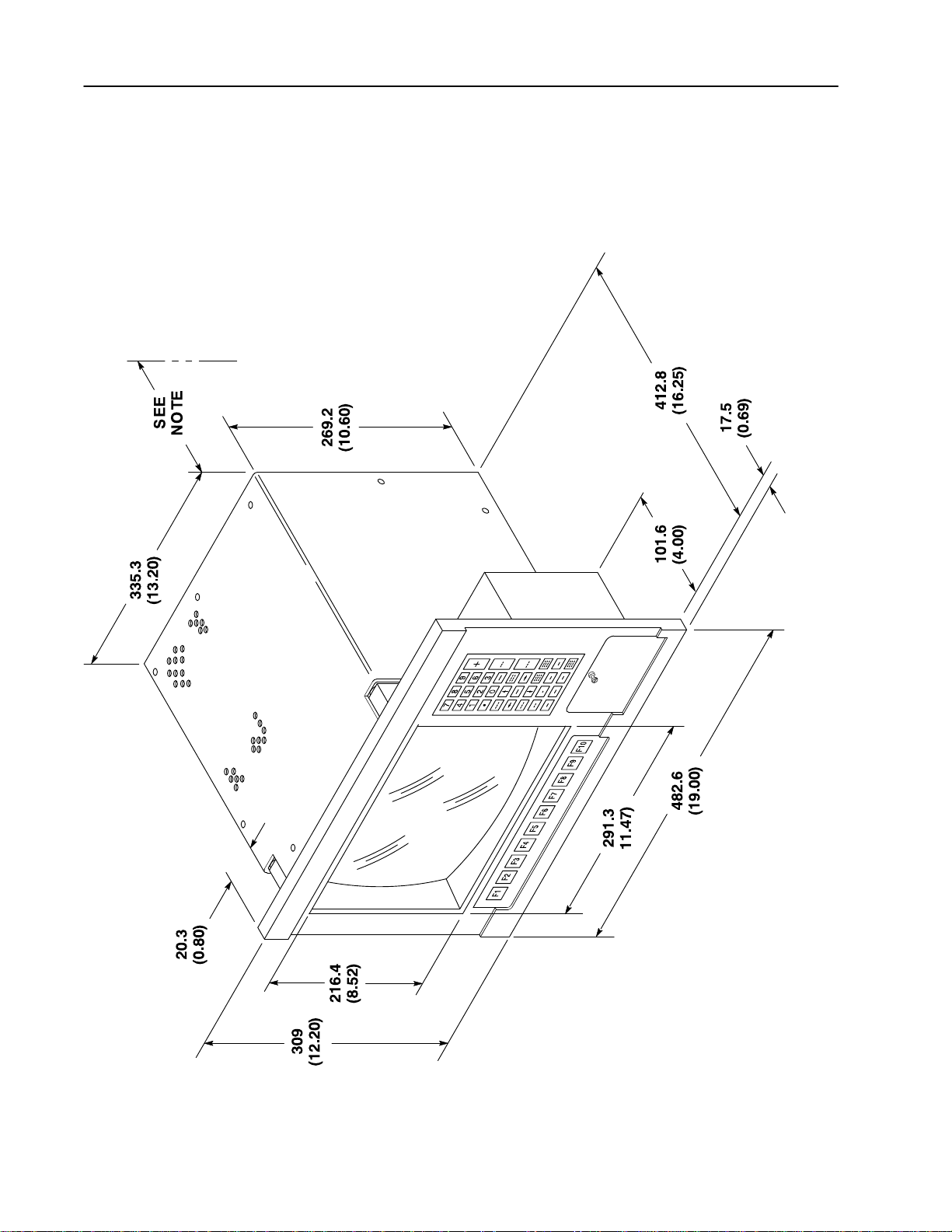
Figure 1
Bulletin 6156 Industrial Monitor (With Keypads)
Physical Dimensions
Publication 6156-2.0
Note: Be sure to allow at least 76.2 mm (3.0 in.) depth clearance for cable connections and air flow.
130680
Page 5
309
(12.20)
216.4
(8.52)
20.3
(0.80)
Industrial 14” CRT Monitors 5
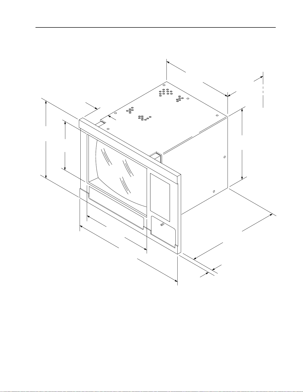
Figure 2
Bulletin 6156 Industrial Monitor (Without Keypads) Physical
Dimensions
335.3
(13.20)
SEE
NOTE
269.2
(10.60)
291.3
11.47)
482.6
(19.00)
Note: Be sure to allow at least 76.2 mm (3.0 in.) depth clearance for cable connections and air flow.
412.8
(16.25)
17.5
(0.69)
130681
Publication 6156-2.0
Page 6

Industrial 14” CRT Monitors6
Installation Instructions
Environmental Considerations
The 6156 Industrial Monitor requires a minimum free air space of
76.2 mm (3 in.) behind and 50.8 mm (2 in.) above and below for
proper cooling. Allen-Bradley Industrial Monitors have been
designed to function without cooling fans. Therefore, maintenance of
fan filters and access to them need not be a concern.
Strong magnetic fields near the front of the monitor outside the
enclosure could potentially distort the image over time. This type of
image distortion generally disappears after degaussing occurs.
Allen-Bradley Industrial Monitors automatically degauss each time
AC power is applied, or when the degauss button is pressed.
Note: The internal degauss will not prevent color impurities caused
by local magnetic fields. Make certain the Industrial Monitor’s
enclosure is free of residual magnetism.
Panel Mounting
The panel on which you will mount the Industrial Monitor should be
at least 14 gauge to insure a NEMA 4 seal and proper support for the
unit. The mounting studs attached to the rear of the monitor bezel
will accommodate this minimum thickness panel and panels up to
6.35 mm (0.25 in.) thick.
To install the Bulletin 6156 Industrial Monitor:
1. Confirm that the shipping carton contains a package of 20 10-32
lock nuts and 20 flat washers. You will need 14 nuts and washers
for installation.
2. Refer to the physical dimension drawings (Figures 1 and 2, pages
4 and 5) and confirm that there is adequate space behind the
panel where the unit is to be situated. Remember to allow extra
space for air circulation.
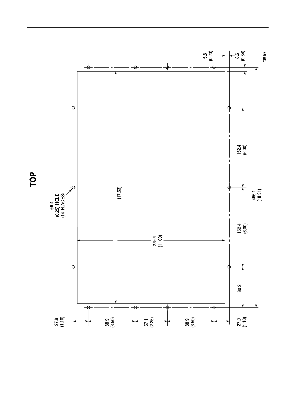
3. Refer to the panel cutout drawing (Figure 3 Page 8) for
dimensions of the panel cutout and mounting hole locations. Cut
and drill the panel.
4. Carefully remove the monitor from its packaging. Avoid
damaging the monitor gasket.
Tip: It will be easier to install the monitor if you support it with a
shelf or other support adjusted to the appropriate height.
Publication 6156-2.0
Page 7

Industrial 14” CRT Monitors 7
5. Insert the monitor in the panel cutout from the front of the panel.
Be careful not to damage the threaded mounting studs as you
position the monitor.
6. Secure the unit with the locknuts and washers provided. Tighten
evenly to 25 inch-pounds of torque.
Important: To assure a proper seal, be sure to install a washer
and nut on each of the 14 mounting studs.
ATTENTION: Mounting nuts must be tightened to a
torque of 25 inch-pounds to provide panel seal and
!
7. Remove the protective adhesive sheet from the screen of the
Industrial Monitor. The sheet is designed to prevent scratching of
the polycarbonate screen protector or the optional touchscreen
during shipping and installation. It should be removed before use.
avoid potential damage to the Bulletin 6156 Industrial
Monitor. Allen–Bradley assumes no responsibility for
water or chemical damage to the Bulletin 6156
Industrial Monitor or other equipment within the
enclosure due to improper installation.
Publication 6156-2.0
Page 8
Industrial 14” CRT Monitors8
Figure 3
Bulletin 6156 Panel Cutout Dimensions
447.7
(3.16)
Publication 6156-2.0
Page 9

Industrial 14” CRT Monitors 9
Connecting AC Power
The Bulletin 6156 Industrial Monitor requires a single phase power
supply providing 100 to 250V AC at 50 to 60 Hz. Power must be
available at a grounded three-pin outlet located nearby. Whenever
possible, connect the monitor to the same AC source that supplies
the computer.
To connect AC power to the monitor:
1. Turn off the main switch or breaker.
2. Use the GND point on the rear panel of the monitor to establish a
chassis to earth ground connection. Secure one end of a ground
strap to the GND point. Connect the other end of the ground strap
to a good earth ground.
The ground terminals are M5 screws.
ATTENTION: Chassis ground must be connected
for safe operation of the monitor. The AC receptacle
!
on the monitor is a 3-wire type with chassis ground
pin, and the mating AC cord supplied is a 3-wire
type, designed for connection to a grounded 3-pin
AC outlet. However a properly grounded AC outlet
is not always available, and grounding using a
3-wire cord can easily be defeated. If you fail to
ground the monitor properly, the setup may result in
personal injury from electrical shock or damage to
equipment.
Product Options
3. Connect the socket end of the AC power cord to the mating
connector on the rear panel of the monitor. Position the power
cord retaining clip attached to the rear panel connector over the
cord’s socket to secure it in place.
4. Connect the plug end of the AC power cord to the mains outlet.
5. Restore AC power to the outlet.
The Bulletin 6156 Industrial 14 in. CRT Monitor can be configured
with the following options.
• VGA or BNC video cables
• keypads
• external keyboard connectors
• touchscreen
Publication 6156-2.0
Page 10

Industrial 14” CRT Monitors10
Video Cables
The Bulletin 6156 Industrial Monitor can be configured with various
industrial grade video cables. The standard HD15 cable is equipped
with a conventional HD15 connector at each end.
Figure 4
Standard Video Cable
1234
678910
11 12
13
5
14 15
HD15
Table A
Standard Video Cable Construction
Monitor HD15
2 Green Video 2
7 Green Video Ground 7
1 Red Video 1
6 Red Video Ground 6
3 Blue Video 3
8 Blue Video Ground 8
5 Composite Sync 5 (Not Used)
11 (Floating) ID0 11
12 (Floating) ID1 12
4 (Gnd) ID2 4
9 Not Connected 9
14 Vertical Sync 14
10 Sync Ground 10
15 Control 15 (Not Used)
13 Horizontal Sync 13
Signal Description Computer HD15
View looking into the Pin End of the
Male connector
Publication 6156-2.0
In addition to the standard video cable, special low noise coaxial
video cables are available in various lengths. They are equipped with
a DB-13C3 connector at the monitor end and a standard HD15
connector at the computer end.
Page 11

Table B
Coaxial Cable Construction
Industrial 14” CRT Monitors 11
Monitor DB-13C3
A1 Center Pin Green Video 2
A1 Outer Green Video Ground 7
A2 Center Pin Red Video 1
A2 Outer Red Video Ground 6
A3 Center Pin Blue Video 3
A3 Outer Blue Video Ground 8
1, 2, 3, 6, 7, 8 Not Connected 4, 9, 11, 12, 15
4 Vertical Sync 14
5 Horizontal Sync Ground 10
9 Vertical Sync Ground 5
10 Horizontal Sync 13
Signal Description Computer HD15
Another low noise video interface is the Differential BNC Input
connectors option which accepts red, green and blue video signals
(RS-343 analog signaling) and a separate composite sync signal from
the video source. BNC to BNC cable options are available.
The Keypad Option
The keypad option provides a 10-key function keypad and a 33-key
pad with numeric keys, cursor keys, and modifier keys. The keypad
keys function just like the equivalent keys on standard IBM AT
keyboards.
Figure 5
The Function Key Pad
Table C
Keypad Scan Code Values
Keypad Legend
F1 3B
F2 3C
F3 3D
F4 3E
F5 3F
F6 40
F7 41
F8 42
F9 43
F10 44
Scan Code (Hex)
Publication 6156-2.0
Page 12

Industrial 14” CRT Monitors12
Figure 6
Numeric Keypad
Table D
Numeric Keypad Functions and Scan Codes
Keypad
Legend
Corresponding AT Key
Scan Code
(Hex)
Keypad
Legend
Corresponding AT Key
Scan Code
(Hex)
7 Number Pad 7 / Home 47 TAB Main Pad Tab 0F
8 Number Pad 8 / Up Arrow 48 ENTER Main Pad Enter 1C
9 Number Pad 9 / Pg Up 49 SPACE Main Pad Space Bar 20
– Number Pad – 4A SHIFT Main Pad Left Shift 2A
4 Number Pad 4 / Left Arrow 4B CTRL Main Pad Left Control 1D
5 Number Pad 5 4C ALT Main Pad Left Alt 38
6 Number Pad 6 / Right Arrow 4D HOME Home E0, 47
+ Number Pad + 4E
↑
Up Arrow E0, 48
1 Number Pad 1 / End 4F PAGE UP Page Up E0, 49
2 Number Pad 2 / Dn Arrow 50
3 Number Pad 3 / Pg Dn 51
←
→
Left Arrow E0, 4B
Right Arrow E0, 4D
0 Number Pad 0 / Ins 52 END End E0, 4F
. Number Pad . / Del 53
↓
Down Arrow E0, 50
* Number Pad * 37 PAGE DOWN Page Down E0, 51
ESC Main Pad Escape 01 INS Insert E0, 52
BACK SPACE Main Pad Back Space 0E DEL Delete E0, 53
PRINT
SCREEN
Print Screen E0, 2A, E0, 37
Publication 6156-2.0
Page 13

Industrial 14” CRT Monitors 13
Keyboard Extender Cables
For units configured with the keypad option, a keyboard extender
cable is available in various lengths.
2
4
1
13
Table E
Standard Keyboard Cable Construction
The Touchscreen Option
The Touchscreen option provides a high resolution resistive or
capacitive touchscreen system. Software drivers provided with the
touchscreen option allow you to use the touchscreen as a pointing
device with many popular DOS and Windows-based industrial
applications. Refer to the touchscreen documentation for information
on installing and using the touchscreen.
5
Female
5
DIN-5
Connector
331
Female DIN–5
1 Keyboard Clock 1
2 Keyboard Data 2
3 Not Used 3
4 0 Volts 4
5 +5V 5
Signal Description Male DIN–5
4
Male
DIN-5
Connector
13
(Computer End)
2
Touchscreen Serial Cables
For units configured with the touchscreen option, a touchscreen
serial cable is available in various lengths and with either a 9-pin or
25-pin communications port D-shell.
Table F
Allen–Bradley Touchscreen Serial (RS-232) Cable Construction
9-pin D Signal Description 9-pin D
1 Not Connected 1
2 Transmit Data 2
3 Receive Data 3
4 Data Terminal Ready (DTR) 4
5 Common Signal Return 5
6 Not Connected 6
7 Request To Send (RTS) 7
8 Clear To Send (CTS) 8
9 Not Connected 9
Cable shield is grounded through the connector shells
Publication 6156-2.0
Page 14

Industrial 14” CRT Monitors14
Connecting to a Computer
(female)
(male)
Connect the Industrial Monitor to a computer with a video cable. A
keyboard extender cable is required for monitors equipped with the
keypad option. A touchscreen serial cable is required for monitors
equipped with the touchscreen option. To connect your monitor to a
computer:
1. Plan the route for the cables through the enclosure and confirm
that the cables you have ordered are long enough for the routing
you have chosen.
Figure 7
Rear Panel of Monitor
Sync Selector
RGBCS
Publication 6156-2.0
AC Cable Restraint
Page 15

Industrial 14” CRT Monitors 15
2. If you are using a standard HD15 video cable with the Industrial
Monitor, connect either end of the cable to the 15-pin video input
connector. See the rear panel drawing (Figure 7) to locate the
connector. Tighten the captive screws on the cable connector to
secure it.
Or
If you are using the optional DB-13C3 video interface, connect
the large end of the video cable to the large video input connector.
Tighten the captive screws on the cable connector to secure it.
Or
If you are using the optional 4 BNC video interface, connect the
ends of the BNC video cable to the red, green, blue and
composite sync input connectors.
Note: The 6156 Industrial Monitor has one HD15 video
connector and can be optionally equipped with two different
video connectors. The conventional HD15 connector and the
larger DB-13C3 connector are wired in parallel and constitute a
single interface, or the HD15 and the Differential BNC inputs are
wired in parallel and constitute a single interface.
Note: The DB-13C3 type connector supports special low noise
cables. These video cables are recommended especially for high
noise environments and for longer cable runs. The computer end
of all standard HD15 and optional DB-13C3 cables include a
standard HD15 connector. The BNC cables available are 4 BNC
to 4 BNC connections.
3. For monitors configured with the keypad option and keypad
extender cable, use the 5-pin DIN keyboard cable. Connect the
female end to the monitor’s keypad/auxiliary keyboard output
connector.
Note: When this cable is connected to the computer keyboard
connector, an IBM AT keyboard may be connected to the front
panel 5–pin DIN connector or to the rear panel Auxiliary
Keyboard input connector. Only one auxiliary keyboard input
port can be used at any time.
4. You may use a standard RS-232 cable to support a mouse or other
device connected via the monitor’s RS-232 connector (located
behind the front panel door). Connect one end of the RS-232
cable to the connector labeled ”COM” on the rear panel of the
monitor. A cable with captive screws should be used and they
should be tightened to secure it.
Publication 6156-2.0
Page 16

Industrial 14” CRT Monitors16
5. For monitors configured with the touchscreen option, connect one
end of the serial touchscreen cable to the connector labeled
”AUX1” on the rear panel of the monitor. Tighten the captive
screws to secure it.
6. Route and secure the cables. In cases where the cable crosses a
door hinge, be sure to leave enough excess cable for a loose fit in
all door positions. Bulletin 6156 Industrial Monitor cables are
designed to be flexible, so routing across a hinge should not result
in application failure. The minimum recommended bend radius
for a video cable is 38 mm (1.5 in.).
7. Connect the standard 15-pin connector end of the video cable to
the computer’s video output connector. Tighten the captive
screws on the cable connector to secure it.
8. Connect the keyboard cable to the keyboard input connector on
the computer.
9. Connect the touchscreen cable free end to an appropriate RS-232
communications port on the computer. Tighten the captive screws
on the cable connector to secure it.
10. If you are installing an RS-232 serial communications cable,
connect the free end to an appropriate RS-232 port on the
computer.
11. Coil and secure any extra cable length in a convenient location.
Publication 6156-2.0
Page 17

Industrial 14” CRT Monitors 17
Controls & Indicators
Power Indicator
Size and Position
The following is a summary of the controls and indicators on the
Bulletin 6156 Industrial Monitor.
Figure 8
Controls and Indicators
Brightness and Contrast
Manual Degauss
Raster Rotation
Power Indicator
The presence of AC power at the Bulletin 6156 Industrial Monitor is
indicated by a green LED on the rear panel.
Contrast, Brightness, Size and Position Controls
The Bulletin 6156 Industrial Monitor is equipped with adjustable
contrast and brightness controls. These controls are located on the
rear panel of the unit.
To obtain the best display, first set the contrast control for
comfortable viewing under lighting conditions that match those in
which the monitor will be used. Adjust the brightness control to
increase or decrease the video image’s intensity as required.
Publication 6156-2.0
Page 18

Industrial 14” CRT Monitors18
The monitor is factory preset and normally requires no manual
adjustment for vertical or horizontal alignment. However, four
screwdriver adjustable size and position controls are provided to
permit adjustment if it should ever become necessary. Adjust
controls using a non–metallic insulated 1/8” (3mm) flat screwdriver
passed through the hole(s) of the rear cover. With a suitable full
screen image on display, adjust the Vertical Size for a height of 7.5”
and the Horizontal Size for a width of 10.0”. Adjust Vertical and
Horizontal Position controls as necessary to center the image on the
screen.
Degauss
The monitor is equipped with an automatic degaussing system to
remove residual magnetism from the CRT’s shadow mask at
power-up. Degaussing helps keep the screen free of any color
impurities which might otherwise result from magnetism picked up
by the shadow mask from the earth’s magnetic field when the
monitor is moved.
In addition, a degauss push button is provided on the rear panel. This
manual control can be used if color impurities appear on the screen
while the monitor is in operation.
Note: The internal degauss will not prevent color impurities caused
by local magnetic fields. Make certain the monitor’s enclosure is free
of residual magnetism.
Tip: For best results, perform a manual degauss only after allowing
at least 15 minutes to pass following power-up or a previous manual
degauss.
Raster Rotation
A raster rotation allows for corrections to any display misalignment
which might be present as a result of interaction between the monitor
and an external, low level uniform magnetic field, such as the earth’s
magnetic field.
All CRT displays are affected by the earth’s magnetic field and by
similar low level uniform fields. Generally, the effects of such a field
on the display vary with the display’s spatial orientation relative to
the field lines. For, example, when the Bulletin 6156 Industrial
Monitor’s screen is facing West, the effects of the earth’s field are
minimal, but when the screen is rotated toward the North or South
the display itself can exhibit a small amount of rotation, so that its
top and bottom edges are no longer parallel to the edges of the panel.
Publication 6156-2.0
Page 19

Industrial 14” CRT Monitors 19
Note: This effect is different from the effect of magnetism on the
shadow mask, which takes the form of color impurity and is
corrected by the degaussing system described previously.
Before making any adjustment, display a full screen image and check
for rotation (top or bottom edge of the image out of parallel with the
corresponding edge of the panel).
If adjustment is necessary,
1. Loosen the lock nut on the control shaft.
2. While observing the display (in a mirror if necessary) use a flat
blade screwdriver to adjust the alignment.
Note: Don’t forget to re-tighten the lock nut after the adjustment is
made.
Important: The raster rotation control cannot correct for the effects
of external AC fields such as those produced by large motors,
generators and transformers. Such effects often take the form of
display jitter. Protection against this kind of magnetic interference
requires special shielding.
Maintenance
ATTENTION: Do not attempt to change any
adjustments located on the monitor chassis’ left side
!
(as viewed from the front of the monitor). These
adjustments are for factory trained personnel using
special test and alignment equipment and should not be
required to obtain a good display in the field.
Preparation for Shipment
If it is ever necessary to ship the monitor, first remove it from the
panel in which it has been installed, then securely pack it. To remove
the monitor from the panel, reverse the installation procedure that
begins on page 6. Whenever possible, ship the monitor in its
original container.
ATTENTION: Never try to ship the monitor while it
is mounted in a panel. Doing so could result in damage
!
to the panel or monitor.
Publication 6156-2.0
Page 20

Industrial 14” CRT Monitors20
Fuse replacement
Bulletin 6156 Industrial Monitors are equipped with an AC line fuse,
which is accessible from the rear panel. To replace the fuse:
1. Remove AC power by disconnecting the AC line cord.
2. Use a flat blade screwdriver to unscrew the cap on the fuse
holder.
3. Remove the cap and fuse.
4. Replace the fuse with a 5ST Slo-Blo type rated at 2.5A, 250VAC.
5. Secure the fuse holder cap with the screwdriver.
6. Restore AC power.
Cleaning instructions
To clean the monitor screen protector, use a 50% solution of alcohol
(ethanol or isopropyl) in water on a cotton gauze pad or soft cotton
cloth. Paper products may scratch the surface, and should be
avoided.
Note: The solvent should be applied only to the cloth, and not
directly to the surface to be cleaned.
Publication 6156-2.0
Page 21

Industrial 14” CRT Monitors 21
or
y( )
Color appears wrong
Troubleshooting
The following table can help you identify the potential cause of
problems you may encounter while using the 6156 Industrial
Monitor.
ATTENTION: When attempting to correct a problem,
do not change any adjustments located on the monitor
!
chassis’ left side (as viewed from the front of the
monitor). These adjustments are for factory trained
personnel using special test and alignment equipment.
Symptom Possible Cause Procedure
No Video No power Check to see if rear panel LED is illuminated; if not, check power wiring;
check for presence of proper voltage; check AC line fuse
Video cable problem Check for proper video cable installation; replace suspected faulty cable
Brightness/Contrast controls
misadjusted
Images distorted or off-center
or
Video not synced (screen rolls)
Color appears wrong
No keypad communications Keypad cable problem Check for proper cable installation; replace suspected faulty cable
No touchscreen
communications
Other touchscreen failures Various Refer to additional documentation provided with unit from touchscreen
Video adapter not compatible
or misconfigured
Monitor misadjusted
Video cable problem Check for proper video cable installation; replace suspected faulty cable
Sync select switch set
improperly (BNC Version only)
Video cable problem Check for proper video cable installation; replace suspected faulty cable
Build-up of residual
magnetism
Touchscreen cable problem Check for proper cable installation; replace suspected faulty cable
Adjust brightness/contrast controls
Check to insure that the graphics adapter is a VGA type and is configured to
provide a display compatible with the monitor
Adjust width, horizontal position, and vertical position controls
Set sync select switch to correct source
Manually degauss unit
manufacture
Publication 6156-2.0
Page 22

Industrial 14” CRT Monitors22
Specifications
Display
Type CRT, Color
CRT Size 14” Diagonal
Nominal Display Area 10.0” Horizontal x 7.5” Vertical (254mm x 191mm)
Resolution 640 x 480 to 1024 x 768, autosync
Dot Pitch 0.28mm
2
Luminance 40 ft–Lamberts (137 cd/m
with full screen white flood)
Horizontal Scan Rate 30 kHz to 56 kHz
Vertical Scan Rate 40 Hz to 90 Hz
Video Bandwidth 75 MHz
Video Inputs RGB Analog, RS-343A (0.7V peak into 75 Ohms =
100% modulation)
Sync Type Separate Horizontal and Vertical Sync Control. TTL
signal levels.
Sync Polarity Horizontal – Negative or positive
Vertical – Negative or positive
Controls and Indicators Rear panel power–on LED (green), Brightness,
Contrast, Manual Degauss, Horizontal Size, Horizontal
Position, Vertical Size, Vertical Position, Raster Rotation
Electrical
Power Requirement 100–250VAC , 50–60 Hz, single phase
Power Consumption 120W maximum
Connectors
Video Input (rear panel) Female HD15, Female DB-13C3, or 4 BNC
Touchscreen port output (rear
Male 9-pin D
panel AUX1)
RS-232 port (rear panel COM
Female 9-pin D
for units with keypad option
only)
Keypad / Aux keyboard output
Male DIN 5-pin
(rear panel)
Aux keyboard input (rear
Female DIN 5–pin
panel for units with keypad
option only)
Aux keyboard input (behind
Female DIN 5-pin
front panel door, for units with
keypad option only)
RS-232 port (behind front
Male 9-pin D
panel door, for units with
keypad option only)
Publication 6156-2.0
Page 23

Industrial 14” CRT Monitors 23
Specifications (Continued)
Environmental
Operating Temperature
Storage Temperature
Relative Humidity 5% to 95% (non–condensing)
Operating Shock 15g (1/2 sine, 11 msec duration)
Non–operating Shock 30g (1/2 sine, 11 msec duration)
Operating Vibration 0.01 in. p-p 5-17 Hz sine, 1.5g peak, 17-640 Hz sine
Non–operating Vibration 0.2 in. p-p 5-16 Hz sine, 2.5g peak, 16-640 Hz sine
Physical
Faceplate Overall Height 12.2” (310mm)
Faceplate Overall Width 19.0” (483mm)
Overall Depth (from rear
surface of front panel to back)
Net Weight approx. 50lbs (23kg)
Standards Compliance
RF Emissions FCC Class A Certified
Safety (Electrical Shock, Fire) EN60950, UL / C-UL 1950 recognized component
CE Compliance Directives 89/336/EEC, 73/23/EEC
Enclosure UL / C-UL 508 Listed
X–ray Emissions DHHS CFR 21.1020 compliant
0°C to +50°C
–30°C to +70°C
16.3” (414mm)
NEMA 4, 12, 13 (when properly installed in panel)
Publication 6156-2.0
Page 24

IBM is a registered trademark of International Business Machines Corporation
VGA is a trademark of International Business Machines Corporation.
PC AT is a trademark of International Business Machines Corporation
Microsoft is a registered trademark of Microsoft.
Microsoft Windows is a trademark of Microsoft.
Rockwell Automation helps its customers receive a superior return on their investment by bringing
together leading brands in industrial automation, creating a broad spectrum of easy-to-integrate
products. These are supported by local technical resources available worldwide, a global network
of system solutions providers, and the advanced technology resources of Rockwell.
Worldwide representation.
Argentina • Australia • Austria • Bahrain • Belgium • Bolivia • Brazil • Bulgaria • Canada • Chile • China, People’s Republic of • Colombia • Costa Rica • Croatia • Cyprus
Czech Republic
Hungary
The Netherlands
Arabia
United Kingdom
Rockwell Automation Headquarters, 1201 South Second Street, Milwaukee, WI 53204-2496 USA, Tel: (1) 414 382-2000 Fax: (1) 414 382-4444
Rockwell Automation European Headquarters, Avenue Hermann Debroux, 46, 1160 Brussels, Belgium, Tel: (32) 2 663 06 00, Fax: (32) 2 663 06 40
Rockwell Automation Asia Pacific Headquarters, 27/F Citicorp Centre, 18 Whitfield Road, Causeway Bay, Hong Kong, Tel: (852) 2887 4788, Fax: (852) 2508 1846
World Wide Web: http://www.ab.com
Publication 6156-2.0 – March 1997 40061-392-01(A)
•
Denmark • Dominican Republic • Ecuador • Egypt • El Salvador • Finland • France • Germany • Ghana • Greece • Guatemala • Honduras • Hong Kong
•
Iceland • India • Indonesia • Iran • Ireland •Israel • Italy • Jamaica • Japan • Jordan • Korea • Kuwait • Lebanon • Macau • Malaysia • Malta • Mexico •Morocco
•
•
Singapore • Slovakia • Slovenia • South Africa, Republic of • Spain • Sweden •Switzerland • T aiwan • Thailand • Trinidad • Tunisia • Turkey • United Arab Emirates
New Zealand • Nigeria • Norway • Oman • Pakistan • Panama • Peru • Philippines • Poland • Portugal • Puerto Rico • Qatar • Romania • Russia • Saudi
•
United States • Uruguay • Venezuela
Publication 6156-2.0 – March 1997
Copyright 1997 Allen-Bradley Company, Inc. Printed in USA
 Loading...