

Page 1
505 z 509
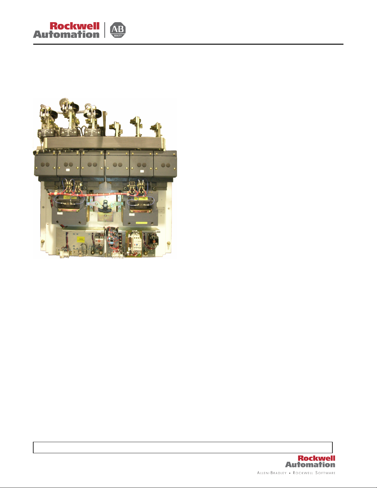
FULL VOLTAGE STARTERS z SIZE 8
SERIES B CONSTRUCTION
BULLETIN
CONTACTS
contacts are of cadmium oxide silver. Square, solid
seating prevents twisting or sliding motion and
extends contact life.
These contacts should not be filed or dressed.
- The weld-resistant, double break
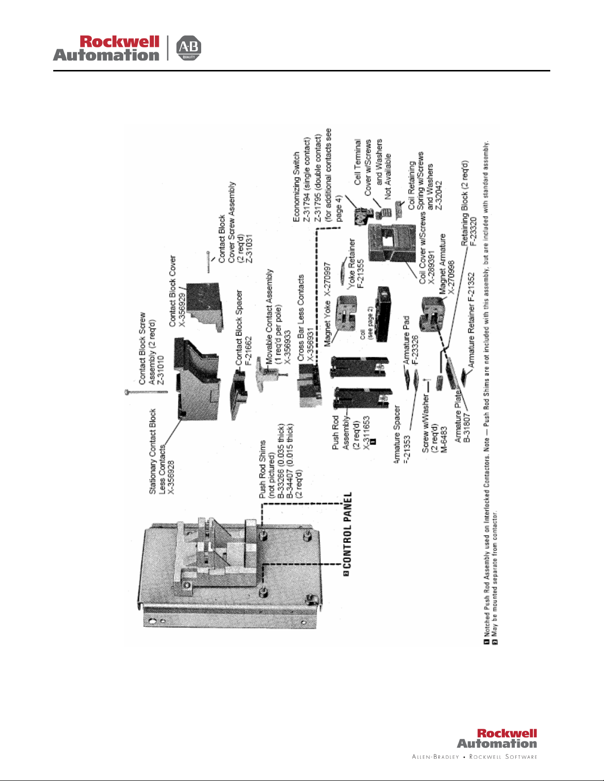
Removal of the contact block cover makes the
mounting screws for the front stationary contact
assembly accessible. The contacts are brazed on
heavy copper parts which are attached to the
stationary contact block by two screws. Remove
these screws and extract the front stationary contact
assembly by depressing the movable contact. To
take out the rear stationary contact assembly, simply
remove the coil cover and slide out the cross bar
assembly, which includes the following items: cross
bar, push rod assemblies, and the magnet armature
assembly. With the cross bar assembly out, the
mounting screws for the rear stationary contacts
accessible and they can be removed along with the
arc quenchers which are attached to the stationary
contact block.
Knowledgebase Technotes ID # Q18318, can be found at http://support.rockwellautomation.com/
The movable contacts are carried in stainless steel
cages which in turn are mounted in cavities in the
molded portion of the cross bar. This cage assembly
is held in place by a screw which can be loosened
from the underside. Therefore, to replace movable
contacts, it is only necessary to replace the
assembly with a new assembly.
STATIONARY CONTACT BLOCK molded contact block has a high degree of
mechanical strength and dimensional accuracy.
Material resists arc tracking and arc blast damage.
Separate arc chambers contain efficient metal arc
quenchers.
To detach the stationary contact block, remove the
contact block cover which is held in place by two
captive screws. Then take out the two contact block
screws which hold the stationary contact block to the
base assembly. The contact block can now be
detached.
CROSS BAR ASSEMBLY
cross bar carrying the movable contacts is molded,
but the movable contacts are carried in stainless
steel cages which in turn are mounted in cavities in
the molded portion. The push rod assemblies are
attached to the cross bar molding with screws which
clamp together two sides of a dovetail joint to make
a very rigid connection. The push rod assemblies
are molded with insert studs at the lower end which
are used to fasten the lower cross member which is
a steel plate going through the armature iron. Make
certain that upon replacement the push rod
assemblies lie against the shoulder of the cross
bar.
The cross bar is available less the movable
contacts. However, if the movable contacts are
needed, they can be purchased as a completed
assembly. The push rod assemblies are obtainable
as separate items. The magnet armature assembly
can be disassembled and its parts procured
separately. Part numbers for each item can be found
on Page 3 and 4.
To remove the cross bar assembly: first, detach
contact block cover whish is held in place by two
captive screws; second, loosen the screws on the
- The portion of the
The hot-
Page 1 of 10
Page 2
505 z 509
BULLETIN
coil retaining spring; third, loosen the four captive
screws holding down the coil cover; and fourth, slide
off the coil cover. The cross bar assembly, as one
unit, is then lifted out. Disassembly of all parts of the
cross bar assembly is easily accomp-lished by
loosening all the nuts and screws on the push rod
assemblies.
MAGNET ARMATURE ASSEMBLY – The magnet
armature is laminated and is mounted on the
armature plate with a rubber pad to absorb shock
and prolong life. To remove the magnet armature
assembly, loosen the lock nut at the lower end of the
push rods. Note – Removal of the magnet
armature assembly will probably cause the push
rod shims to fall free. Be sure that upon
replacing the magnet armature assembly, the
push rod shims are placed in the same position,
so that consistent overtravel may be maintained.
Take out the retaining blocks located on each side of
the magnet armature. Force the armature plate
through the armature, thereby isolating the magnet
armature. Note - The armature pad, spacer, and
retainer must be replaced in the same order. For
correct replacement, refer to the exploded view
on Page 3.
MAGNET YOKE
and mounted on an aluminum base casting. The
pressure molded coil is mounted with the yoke
projecting into the openings of the coil so that the
coil slides out with the magnet yoke.
OPERATING COIL
in a coil protected against mechanical damage and
the corrosive effects of atmospheric conditions and
protects the coil against swelling when subjected to
over-voltage. Very little trouble can be expected
from the operating coils.
Removing the coil is a simple operation that is
easily performed from the front. First, remove the
coil terminal cover; second, detach the coil leads;
third, loosen the two
screws located on the coil retaining spring; and
fourth, slacken the four captive screws holding down
the coil cover. The coil cover is then lifted out from
the font. Now remove the operating coil and magnet
yoke and detach the yoke from the coil.
To replace the operating coil, first insert the
magnet yoke into the operating coil. After this has
been accomplished, insert both the operating coil
and the magnet yoke, as a unit, into the switch unit
– The magnet yoke is laminated
– Unique high-pressure results
securely. Now replace the coil cover into the switch
unit, but do not tighten the screws on the coil
retaining spring. Be sure to place the auxiliary
contact operating lever into the auxiliary contact
actuator fastened to the cross bar.
on page 3.)
and the four captive screws on the coil cover.
Restore the coil leads and put back the coil terminal
cover.
NOTE
into the control transformers with 120 volt, 60 Hz
secondary.
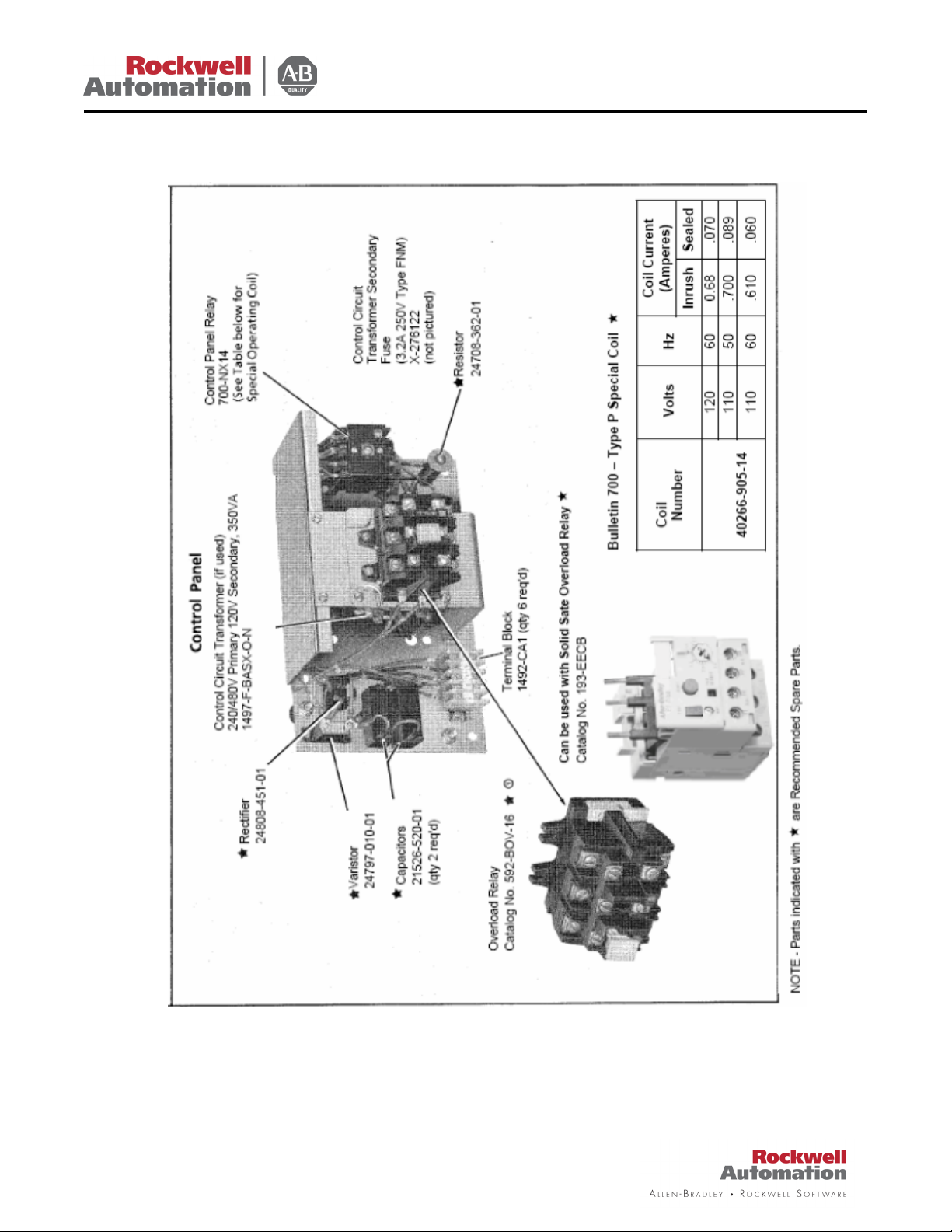
CONTROL PANEL
capacitor, rectifier, resistors, contact protector,
terminal blocks and control transformer (when used)
– is mounted in a metal cabinet. The cabinet is
normally mounted below the starter, but may be
mounted separate from the starter. The cabinet
(when below starter) is mounted on rubber
grommets to absorb heavy shock during opening
and closing of starter. The control panel has a
hinged cover which can be swung out for inspection
or to check wiring of auxiliary equipment.
BULLETIN 1495 AUXILIARY CONTACTS –
Provisions are made for two auxiliary contacts in
addition to the one which is required for the
economizing action. Each auxiliary contact provides
two independent circuits, either of which can be set
as normally open and normally closed, depending
on the circuit requirements. (
Tighten the coil retaining spring screws
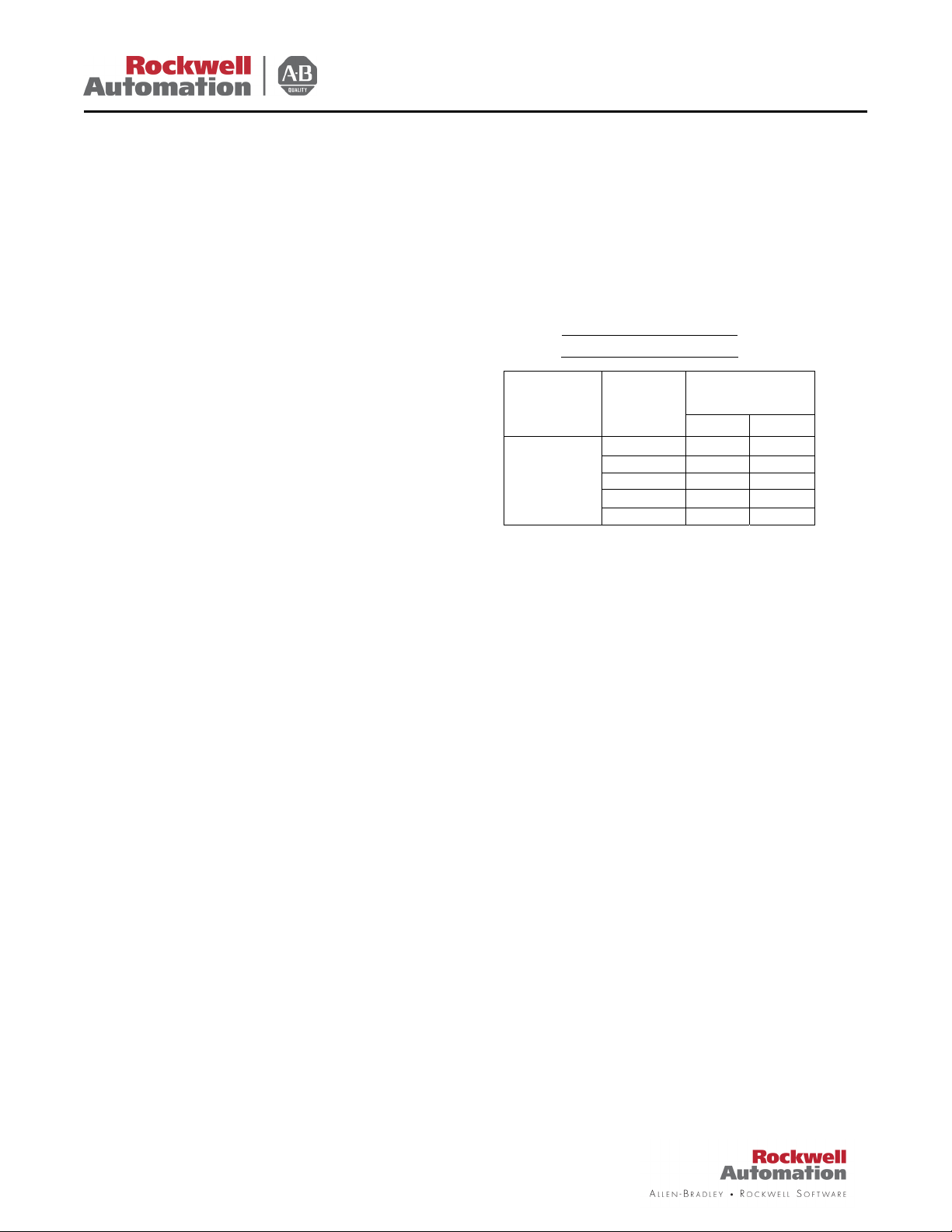
Operating Coil
Coil
Number
107D206
(90V DC)
volts
120 17.6 .392
208 10.2 .226
240 8.8 .196
480 4.4 .093
600 3.5 .078
Coil Current
(Amperes)
Inrush sealed
– Given values are input current (amperes)
- All auxiliary equipment –
See Instructions - Page 6.)
(See instructions
Page 2 of 10
Page 3
505 z 509
BULLETIN
Page 3 of 10
Page 4

505 z 509
BULLETIN
Page 4 of 10
Page 5
505 z 509
BULLETIN
Page 5 of 10
Page 6

505 z 509
BULLETIN
Bulletin 592 Manual Reset Overload Relay
Optional: Bulletin 193 E1 Plus Solid State Overload
Relay
(See Page 5)
ORDERING INFORMATION – Your order cannot be
entered unless the following information is given:
Part number, description of part and series letter of
starter. This renewal parts list applies also to these
starters when used on control apparatus listed under
other Bulletin numbers.
BULLETIN 1495 AUXILIARY CONTACT KITS
Catalog Number 1495-J6 (Single Contact)
Catalog Number 1495-K6 (Double Contact)
Overload Relay
CHANGING BULLETIN 1495 AUXILIARY CONTACT
FROM NORMALLY OPEN TO NORMALLY CLOSED
AND VICE VERSA
Auxiliary Contact from Normally Open to Normally
Closed and vice versa, first loosen the screw which
holds the drive plate and adjusting plate together.
Then lift the drive plate as shown in the illustration.
Now rotate the adjusting plate to the opposite hole
and snap the drive plate into place. Then tighten the
screw. Double contact auxiliary switches have
isolated circuits; therefore, each side must be
adjusted independently.
TYPICAL WIRING DIAGRAM – (See applicable
codes and laws - Schematic is shown on page 7)
– To change the Bulletin 1495
MOUNTING INSTRUCTION – To mount the Bulletin
1495 Auxiliary Contact place the auxiliary contact
operating lever into the auxiliary contact actuator
fastened to the cross bar. Tighten the two mounting
screws on the auxiliary contact to the coil cover. The
cross bar will now engage the operating lever of the
auxiliary contact.
Page 6 of 10
Page 7

505 z 509
BULLETIN
Page 7 of 10
Page 8

505 z 509
BULLETIN
Spare part List for Bulletin 505, Size 8
Part Number Part Description QTY Part Number Part Description QTY
X-356928 Stationary Contact Block Less Contacts 1 M-922 Support Screw 1
Z-31010 Contact Block Screw Assembly 2 B-32105 Locking Plate 1
X-356929 Contact Block Cover 1 199-LG1 Lug 3
Z-31031 Contact Block Cover Screw Assembly 2 G-13422 Front Terminal Extension 1
F-21662 Contact Block Spacer 1 B-35910 Locking Plate 1
X-356933 Movable Contact Assembly 1 X-319610 Front Terminal Assembly 1
X-356931 Cross Bar Less Contacts 1 X-298507
B-33266 Push Rod Shims (0.035 thick) 2 M-7693 Screw 1
B-34407 Push Rod Shims (0.015 thick) 2 M-103 Lock Washer 1
Z-31794 Single Contact 1 M-248 Lock Washer 1
Z-31795 Double Contact 1 M-471 Screw 1
X-270997 Magnet Yoke 1 M-180 Lock Washer 1
F-21355 Yoke Retainer 1 M-5683 Washer 1
X-2311653 Push Rod Assembly 2 M-22 Iron Nut 1
F-21353 Armature Spacer 1 M-165 Screw 1
F-23326 Armature Pad 1 M-756 Screw 1
M-6483 Screw w/Washer 2 M-7692 Screw 1
B-31807 Armature Plate 1 M-1100 Lock Washer 1
F-21352 Armature Retainer 1 M-12 Lock Washer 1
F-23320 Retaining Block 2 M-144 Screw 1
X-270998 Magnet Armature 1 M-1552 Terminal Screw 1
X-289391 Coil Cover w/Screws 1 24808-451-01 Rectifier 1
Z-32042
B-35910 Locking Plate 1 21526-520-01 Capacitors 2
B-32105 Locking Plate 1 1492-CA1 Terminal Block 6
199-LC1 Lug 3 24708-362-01 Resistor 1
G-13411 Rear Terminal Extension 1 X-276122
B-33300 Control Terminal 1 700-NX14 Control Panel Relay 1
X-319611 Rear Terminal Assembly 1 193-EECB E1 Plus Solid Sate Overload Relay 1
X-298508
B-34853 Transformer Clamp 1 193-ERA E1 Plus Reset Adapter 1
M-2185 Clamp Screw 1 193-BC8 E1 Plus Shield 1
M-6 Clamp Washer 1 A40266-601-01 700P Control relay 1
M-7 Clamp Nut 1 A40185-450-02 Over current Relay 1
X-316050
B-34612 Transformer Support 1 700-P220A1 Industrial relay 1
M-6 Support Washer 1
Coil Retaining Spring w/Screws and
Washers
Rear Contact Assembly w/Screws &
Washers
Current Transformer (1200 to 5 amp
ratio)
1 24797-010-01 Varsitor 1
1 193-EPB E1 Plus Adapter 1
1 A40460-002-01 Insulation, Resistor 1
Front Contact Assembly w/Screws &
Washers
Transformer Sec. fuse (3.2A 250V Type
FNM)
1
1
Page 8 of 10
Page 9

505 z 509
BULLETIN
Page 9 of 10
Page 10

505 z 509
BULLETIN
Publication 505-QS001A-EN-P – November 2006 Copyright © 2006 Rockwell Automation, Inc. All rights reserved. Printed in the USA.
 Loading...