

Page 1
Instructions
B
lock
b
N. O. Pole Conversion Kits
500LC–2PCK, 500LC–4PCK,
500LC–6PCK, 500LC–LS3 for
Bulletin 500LC Lighting Contactors
Use these instructions to change poles on Bulletin 500LC Lighting Contactors.
Contact
Kit No.
500LC–2PCK
500LC–4PCK
500LC–6PCK
500LC–LS3
Kit
num
of Poles
2 1top
4 1top
6 1top 1top 1top 2both
leaf spring 1 1 1
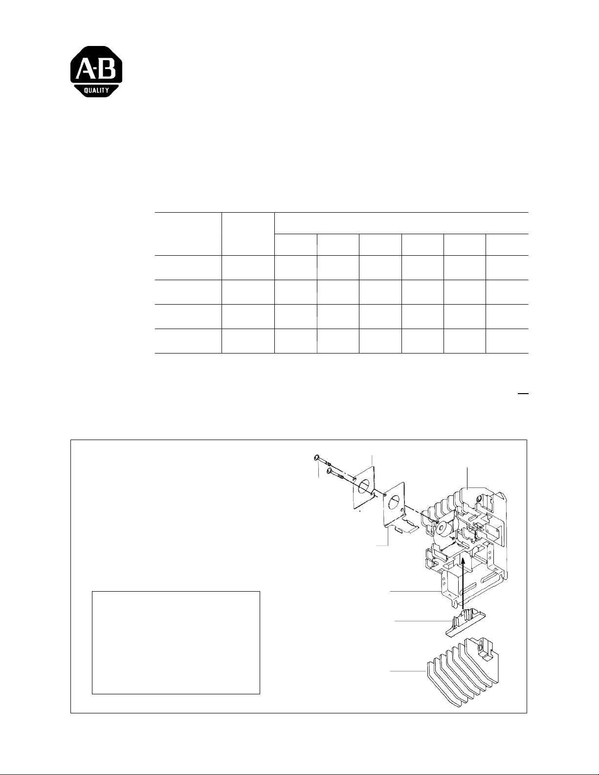
A new and different contact block is needed in the lighting contactor when
the number of poles is changed. A leaf spring must be used on 2–...6–pole
(without a bottom contact block). Two actuators are used on all
configurations. When changing poles, also change catalog number on
nameplate.
Number of Contactor Poles (Normally Ope n )
er
2 4 6 8 10 12
1
bottom
1
bottom
Recommended Tools Screwdriver and scriber (to change nameplate catalog number)
upper
contact block
Tighten nameplate screws
evenly to 10 in–lb.
Be sure to change the catalog
number on the nameplate.
nameplate
nameplate screw
CAM / CORE must be white.
This kit should not be applied
to Lighting Contactors with
black CAM / CORE.
*leafspringisnotused
on 8–...12–pole
When a lower contact block is
added remove the leafspring.
Two actuators are always
used (top and bottom).
leaf spring *
(2–...6–pole only)
base
actuator
(2 used; 1 top, 1 bottom)
lower
contact block
Figure 1 Contact block and actuator
Publication 500LC–IN004A–EN–P May 2005
Page 2
Installing Pole Conversion Kits 500LC–2PCK, 4PCK, 6PCK, LS3 to Bulletin 500LC Lighting Contactors
Pol
2
A
2Pole
B
4Pole
C
6Pole
D
8Pole
E
10 Pole
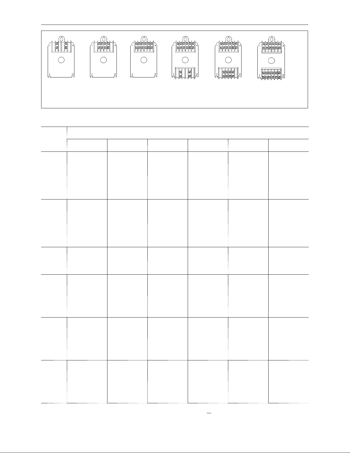
Figure 2 Location of contact block(s) in relation to number of poles
TableA–N.O.PoleConversionKits
top
bottom
F
12 Pole
To t al
es
Needed 2
2
see
Fig. 2A
4
see
Fig. 2B
6
see
Fig. 2C
8
see
Fig. 2D
10
see
Fig. 2E
12
see
Fig. 2F
Number of Poles on Exi st in g Bulletin 500LC Li ght i ng Contactor
4 6 8 10 12
Remove top block.
Remove bottom
block and
reinstall it on top.
Install a new
leaf spring
500LC–LS3
on bottom.
Remove top block.
Install new block
500LC–4PCK
on top. Remove
bottom block.
Install a new
leaf spring
500LC–LS3
on bottom.
Remove bottom
block. install a
new leaf spring
500LC–LS3.
Remove bottom
block. Install
new block
500LC–4PCK
on the bottom.
Remove bottom
block. Install
new block
500LC–6PCK
on the bottom.
Remove top
block. Install
new block
500LC–4PCK
on top.
Remove top
block. Install
new block
500LC–6PCK
on top.
Remove leaf
spring. Remove
top block and
reinstall it on
bottom. Install
new block
500LC–6PCK
on top.
Remove top block.
Install new block
500LC–6PCK
on top. Remove
leaf spring. Install
another new block
500LC–6PCK
on the bottom.
Remove top
block. Install
new block
500LC–2PCK
on top.
Remove top
block. Install
new block
500LC–6PCK
on top.
Remove top
block. Install
new block
500LC–2PCK
on top.
Remove leaf
spring. Remove
top block and
reinstall it on
bottom. Install
new block
500LC–6PCK
on the top.
Remove top block.
Install new block
500LC–6PCK
on top. Remove
leaf spring. Install
another new block
500LC–6PCK
on the bottom.
Remove top
block. Install
new block
500LC–2PCK
on top.
Remove top
block. Install
new block
500LC–4PCK
on top.
Remove leaf
spring. Install
new block
500LC–2PCK
on the bottom.
Remove leaf
spring. Install
new block
500LC–4PCK
on the bottom.
Remove the leaf
spring. Install
new block
500LC–6PCK
on the bottom.
Remove top block.
Install new block
500LC–2PCK
on top. Remove
bottom block and
install a new
leaf spring
500LC–LS3
on bottom.
Remove top block.
Remove bottom
block and
reinstall it on top.
Install a new
leaf spring
500LC–LS3
on bottom.
Remove bottom
block. install a
new leaf spring
500LC–LS3.
Remove bottom
block. Install
new block
500LC–2PCK
on bottom.
Remove bottom
block. Install
new block
500LC–6PCK
on the bottom.
Remove top block.
Install new block
500LC–2PCK
on top. Remove
bottom block and
install a new
leaf spring
500LC–LS3
on bottom.
Remove top block.
Install new block
500LC–4PCK
on top. Remove
bottom block and
install a new
leaf spring
500LC–LS3
on bottom.
Remove bottom
block. install a
new leaf spring
500LC–LS3.
Remove bottom
block. Install
new block
500LC–2PCK
on bottom.
Remove bottom
block. Install
new block
500LC–4PCK
on the bottom.
NOTE: T op and bottom actuators are required for all configurations;
top actuator with a contact block, bottom actuator with a contact block or a leaf spring.
Publication 500LC–IN004A–EN–P May 2005
Page 3

Installing Pole Conversion Kits 500LC–2PCK, 4PCK, 6PCK, LS3 to Bulletin 500LC Lighting Contactors
How to Install a Contact Block
3
1. Open circuit breakers, then use a voltmeter to verify no voltage is present at
2. Label, disconnect, and tape all wires (control, line, load) from the lighting
3. Loosen the mounting screws and remove the Bulletin 500LC Lighting
Disassembly
The contact blocks are mounted on the top and bottom of the lighting contactor.
A bottom contact block is used only for lighting contactors with more than six
poles. See Figure 2 and Table A.
1. Remove the contact block(s). Skip this step if it is not necessary to move or
2. Remove leaf spring if converting a 2–...6–pole lighting contactor to an
Reassembly
Be sure the contact blocks and actuator are correct for the number of poles
required. Lighting contactors with more than six poles use two contact blocks.
When two are used, always mount the six pole contact block on the top of the
lighting contactor. See Figure 2 and Table A.
1. Slide the actuator into the cavity (roller facingin, with the guides facingaway
2. With actuator(s) already installed, install the new contact block(s) onto the
3. Converted lighting contactors must be assembled as shown with contact blocks as
4. Use a scriber to change the nameplate catalog number (number of poles).
5. Install the manual operat ing screw. Insert the #8–32 screw (fromthe kit) into
6. Manually operate the lighting contactor. Use the plastic screw to close and
CAUTION
To avoid personal injury or property
damage, de–energize both line and control
power connected to the Bulletin 500LC
Lighting Contactor before proceeding.
both control and line terminal screws.
contactor.
Contactor from the enclosure.
remove a contact block. Loosen the two screws in each contact block. Then
pull the contact block straight out.
Do not remove the captive screws from the conta ct block. The lower actuator
may drop out when the bottom contact block is removed.
8–...12–pole lighting contactor. For leaf spring removal see Figure 1.
Note: When converting an 8–...12–pole N.O. lighting contactor to a
2–...6–pole lighting contactor a leaf spring and new actuator must be installed.
SeeFigure1.
from the base of the lighting contactor) before installing the contact block.
base. Tighten the two screws in each contact block to 10 in–lb. See Figure 1.
shown in Figure 2. If any contact blocks are removed to accomplish the
conversion, a leaf spring must be installed.
the center of the coil and carefully turn it clockwise until the threads engage
thecam/core.SeeFigure3.Tightenhandtight.SeeFigure3.
open the lighting contactor by pushing it inward and pulling it outward.
Observe the buttons in the contact blocks(s); the contacts are open when the
buttons are out. The action should be smooth, without any binding. If not,
recheck alignment of contact block(s) and actuator.
Publication 500LC–IN004A–EN–P May 2005
Page 4

Installing Pole Conversion Kits 500LC–2PCK, 4PCK, 6PCK, LS3 to Bulletin 500LC Lighting Contactors
4
Re mo ve the plastic operat in g screw !
7. Remove the plastic operating screw from the lighting contactor.
8. Reinstall the lighting contactor into the enclosure and tighten the mounting
screws.
9. Reconnect all wires previously removed. Tighten control connections to
10 in–lb. Tighten the line and load connectio ns to 18 in–lb.
10. Close circuitbreakers and check electrical operation of the lighting contactor
with the new control voltage.
manual
operating
screw
push — pull
Do not manually operate
until all power and control
circuits are disconnected.
Figure 3 Manual operating screw
Publication 500LC–IN004A–EN–P May 2005
2005 Rockwell Automation. All rights reserved. Printed in USA.
381339–266
 Loading...